WO2016136267A1 - Appareil de réfrigération pour conteneur - Google Patents
Appareil de réfrigération pour conteneur Download PDFInfo
- Publication number
- WO2016136267A1 WO2016136267A1 PCT/JP2016/001026 JP2016001026W WO2016136267A1 WO 2016136267 A1 WO2016136267 A1 WO 2016136267A1 JP 2016001026 W JP2016001026 W JP 2016001026W WO 2016136267 A1 WO2016136267 A1 WO 2016136267A1
- Authority
- WO
- WIPO (PCT)
- Prior art keywords
- air
- outside
- container
- space
- storage space
- Prior art date
- Legal status (The legal status is an assumption and is not a legal conclusion. Google has not performed a legal analysis and makes no representation as to the accuracy of the status listed.)
- Ceased
Links
Images







Classifications
-
- F—MECHANICAL ENGINEERING; LIGHTING; HEATING; WEAPONS; BLASTING
- F25—REFRIGERATION OR COOLING; COMBINED HEATING AND REFRIGERATION SYSTEMS; HEAT PUMP SYSTEMS; MANUFACTURE OR STORAGE OF ICE; LIQUEFACTION SOLIDIFICATION OF GASES
- F25D—REFRIGERATORS; COLD ROOMS; ICE-BOXES; COOLING OR FREEZING APPARATUS NOT OTHERWISE PROVIDED FOR
- F25D17/00—Arrangements for circulating cooling fluids; Arrangements for circulating gas, e.g. air, within refrigerated spaces
- F25D17/04—Arrangements for circulating cooling fluids; Arrangements for circulating gas, e.g. air, within refrigerated spaces for circulating air, e.g. by convection
- F25D17/042—Air treating means within refrigerated spaces
-
- A—HUMAN NECESSITIES
- A23—FOODS OR FOODSTUFFS; TREATMENT THEREOF, NOT COVERED BY OTHER CLASSES
- A23B—PRESERVATION OF FOODS, FOODSTUFFS OR NON-ALCOHOLIC BEVERAGES; CHEMICAL RIPENING OF FRUIT OR VEGETABLES
- A23B7/00—Preservation of fruit or vegetables; Chemical ripening of fruit or vegetables
- A23B7/04—Freezing; Subsequent thawing; Cooling
- A23B7/0425—Materials not being transported through or in the apparatus, with or without shaping, e.g. in the form of powders, granules or flakes
-
- A—HUMAN NECESSITIES
- A23—FOODS OR FOODSTUFFS; TREATMENT THEREOF, NOT COVERED BY OTHER CLASSES
- A23B—PRESERVATION OF FOODS, FOODSTUFFS OR NON-ALCOHOLIC BEVERAGES; CHEMICAL RIPENING OF FRUIT OR VEGETABLES
- A23B7/00—Preservation of fruit or vegetables; Chemical ripening of fruit or vegetables
- A23B7/14—Preserving or ripening with chemicals not covered by group A23B7/08 or A23B7/10
- A23B7/144—Preserving or ripening with chemicals not covered by group A23B7/08 or A23B7/10 in the form of gases, e.g. fumigation; Compositions or apparatus therefor
- A23B7/148—Preserving or ripening with chemicals not covered by group A23B7/08 or A23B7/10 in the form of gases, e.g. fumigation; Compositions or apparatus therefor in a controlled atmosphere, e.g. partial vacuum, comprising only CO2, N2, O2 or H2O
-
- B—PERFORMING OPERATIONS; TRANSPORTING
- B65—CONVEYING; PACKING; STORING; HANDLING THIN OR FILAMENTARY MATERIAL
- B65D—CONTAINERS FOR STORAGE OR TRANSPORT OF ARTICLES OR MATERIALS, e.g. BAGS, BARRELS, BOTTLES, BOXES, CANS, CARTONS, CRATES, DRUMS, JARS, TANKS, HOPPERS, FORWARDING CONTAINERS; ACCESSORIES, CLOSURES, OR FITTINGS THEREFOR; PACKAGING ELEMENTS; PACKAGES
- B65D88/00—Large containers
- B65D88/74—Large containers having means for heating, cooling, aerating or other conditioning of contents
- B65D88/745—Large containers having means for heating, cooling, aerating or other conditioning of contents blowing or injecting heating, cooling or other conditioning fluid inside the container
-
- F—MECHANICAL ENGINEERING; LIGHTING; HEATING; WEAPONS; BLASTING
- F25—REFRIGERATION OR COOLING; COMBINED HEATING AND REFRIGERATION SYSTEMS; HEAT PUMP SYSTEMS; MANUFACTURE OR STORAGE OF ICE; LIQUEFACTION SOLIDIFICATION OF GASES
- F25D—REFRIGERATORS; COLD ROOMS; ICE-BOXES; COOLING OR FREEZING APPARATUS NOT OTHERWISE PROVIDED FOR
- F25D11/00—Self-contained movable devices, e.g. domestic refrigerators
- F25D11/003—Transport containers
-
- F—MECHANICAL ENGINEERING; LIGHTING; HEATING; WEAPONS; BLASTING
- F25—REFRIGERATION OR COOLING; COMBINED HEATING AND REFRIGERATION SYSTEMS; HEAT PUMP SYSTEMS; MANUFACTURE OR STORAGE OF ICE; LIQUEFACTION SOLIDIFICATION OF GASES
- F25D—REFRIGERATORS; COLD ROOMS; ICE-BOXES; COOLING OR FREEZING APPARATUS NOT OTHERWISE PROVIDED FOR
- F25D17/00—Arrangements for circulating cooling fluids; Arrangements for circulating gas, e.g. air, within refrigerated spaces
- F25D17/04—Arrangements for circulating cooling fluids; Arrangements for circulating gas, e.g. air, within refrigerated spaces for circulating air, e.g. by convection
- F25D17/042—Air treating means within refrigerated spaces
- F25D17/045—Air flow control arrangements
-
- F—MECHANICAL ENGINEERING; LIGHTING; HEATING; WEAPONS; BLASTING
- F25—REFRIGERATION OR COOLING; COMBINED HEATING AND REFRIGERATION SYSTEMS; HEAT PUMP SYSTEMS; MANUFACTURE OR STORAGE OF ICE; LIQUEFACTION SOLIDIFICATION OF GASES
- F25D—REFRIGERATORS; COLD ROOMS; ICE-BOXES; COOLING OR FREEZING APPARATUS NOT OTHERWISE PROVIDED FOR
- F25D17/00—Arrangements for circulating cooling fluids; Arrangements for circulating gas, e.g. air, within refrigerated spaces
- F25D17/04—Arrangements for circulating cooling fluids; Arrangements for circulating gas, e.g. air, within refrigerated spaces for circulating air, e.g. by convection
- F25D17/06—Arrangements for circulating cooling fluids; Arrangements for circulating gas, e.g. air, within refrigerated spaces for circulating air, e.g. by convection by forced circulation
-
- F—MECHANICAL ENGINEERING; LIGHTING; HEATING; WEAPONS; BLASTING
- F25—REFRIGERATION OR COOLING; COMBINED HEATING AND REFRIGERATION SYSTEMS; HEAT PUMP SYSTEMS; MANUFACTURE OR STORAGE OF ICE; LIQUEFACTION SOLIDIFICATION OF GASES
- F25D—REFRIGERATORS; COLD ROOMS; ICE-BOXES; COOLING OR FREEZING APPARATUS NOT OTHERWISE PROVIDED FOR
- F25D21/00—Defrosting; Preventing frosting; Removing condensed or defrost water
- F25D21/14—Collecting or removing condensed and defrost water; Drip trays
-
- F—MECHANICAL ENGINEERING; LIGHTING; HEATING; WEAPONS; BLASTING
- F25—REFRIGERATION OR COOLING; COMBINED HEATING AND REFRIGERATION SYSTEMS; HEAT PUMP SYSTEMS; MANUFACTURE OR STORAGE OF ICE; LIQUEFACTION SOLIDIFICATION OF GASES
- F25D—REFRIGERATORS; COLD ROOMS; ICE-BOXES; COOLING OR FREEZING APPARATUS NOT OTHERWISE PROVIDED FOR
- F25D23/00—General constructional features
- F25D23/003—General constructional features for cooling refrigerating machinery
-
- A—HUMAN NECESSITIES
- A23—FOODS OR FOODSTUFFS; TREATMENT THEREOF, NOT COVERED BY OTHER CLASSES
- A23V—INDEXING SCHEME RELATING TO FOODS, FOODSTUFFS OR NON-ALCOHOLIC BEVERAGES AND LACTIC OR PROPIONIC ACID BACTERIA USED IN FOODSTUFFS OR FOOD PREPARATION
- A23V2002/00—Food compositions, function of food ingredients or processes for food or foodstuffs
-
- F—MECHANICAL ENGINEERING; LIGHTING; HEATING; WEAPONS; BLASTING
- F25—REFRIGERATION OR COOLING; COMBINED HEATING AND REFRIGERATION SYSTEMS; HEAT PUMP SYSTEMS; MANUFACTURE OR STORAGE OF ICE; LIQUEFACTION SOLIDIFICATION OF GASES
- F25D—REFRIGERATORS; COLD ROOMS; ICE-BOXES; COOLING OR FREEZING APPARATUS NOT OTHERWISE PROVIDED FOR
- F25D2317/00—Details or arrangements for circulating cooling fluids; Details or arrangements for circulating gas, e.g. air, within refrigerated spaces, not provided for in other groups of this subclass
- F25D2317/04—Treating air flowing to refrigeration compartments
Definitions
- the present invention relates to a container refrigeration apparatus that cools the air in a container and adjusts the composition of the air in the container.
- a container refrigeration apparatus including a refrigerant circuit for performing a refrigeration cycle has been used to cool air in a container used for maritime transportation or the like (see, for example, Patent Document 1).
- plants such as bananas and avocado are loaded in the container.
- the plant breathes by taking in oxygen in the air and releasing carbon dioxide. Since the nutrients and moisture stored in the plant are reduced by the respiration of the plant, the freshness of the plant is remarkably lowered when the respiration rate is increased. Therefore, it is preferable that the oxygen concentration in the container is as low as possible so as not to cause respiratory problems.
- Patent Document 1 nitrogen in the air is separated by a membrane separator to generate nitrogen-enriched air having a higher nitrogen concentration than the atmosphere, and this nitrogen-enriched air is supplied into the container to store the inside of the container.
- An internal environment control system for reducing the oxygen concentration of air is disclosed. When the oxygen concentration of the indoor air is lowered by the internal environment control system, the respiration rate of the plant is reduced and the freshness of the plant is easily maintained.
- the conventional container refrigeration apparatus is provided with an exhaust passage that communicates the blow-out side of the internal fan with the outside of the internal storage, and an exhaust valve that opens and closes the exhaust passage. The inside air was exhausted outside by using the pressure difference generated between them.
- the pressure inside the container is lowered and may be lower than the pressure outside the warehouse (atmospheric pressure). .
- the pressure inside the container is lowered and may be lower than the pressure outside the warehouse (atmospheric pressure).
- the pressure inside the container is lowered and may be lower than the pressure outside the warehouse (atmospheric pressure).
- the present invention has been made in view of such a point, and an object of the present invention is to provide a container refrigeration apparatus including an internal air conditioner that adjusts the composition of the internal air. Even if it is a case where it is lower than this pressure, it exists in the structure which enables discharge
- 1st invention attaches to the opening end of the container (11) in which the plant (15) which breathes is stored, and connects the outside storage space (S1) and the container (11 ) In the storage space (S2) connected to the internal storage space (S2), the condenser (22) provided in the external storage space (S1), and the internal storage space (S2).
- a container refrigeration apparatus comprising: an exhaust air passage (46a) that connects the interior of the container (11), and an internal air conditioner (60) that adjusts the composition of the air in the container (11). The end on the outside of the passage (46a) is open on the suction side of the outside
- the refrigerant when the refrigeration cycle is performed in the refrigerant circuit (20) and the internal fan (26) rotates, the refrigerant circulates in the refrigerant circuit (20), and the internal air in the internal storage of the container (11). Circulates.
- the internal air led to the evaporator (24) by the internal fan (26) is cooled by the refrigerant in the refrigerant circuit (20) when passing through the evaporator (24).
- the internal air conditioner (60) supplies nitrogen-enriched air into the container (11), while the air in the container (11) is discharged outside the container through the exhaust passage (46a). By doing so, the composition of the air in the container is adjusted to a desired state.
- the end of the exhaust passage (46a) on the outside of the warehouse is open on the suction side of the outside fan (25) of the outside storage space (S1). Therefore, the pressure on the suction side of the external fan (25) can be made lower than the pressure on the outlet side of the internal fan (26) by the rotation of the external fan (25). That is, even when the pressure inside the container (11) is lower than the pressure of the outside air, the pressure in the space where the inner end of the exhaust passage (46a) opens by the outside fan (25) is stored. The pressure in the space where the outer end opens can be made higher.
- the outside storage space (S1) is divided into an upstream first space (S11) and a downstream second space (S11) by the condenser (22).
- the outside fan (25) is provided in the second space (S12), and only the outlet of the outside fan (25) is provided in the second space (S12). It is closed so as to open to the outside, and the end of the exhaust passage (46a) on the outside of the warehouse is open in the second space (S12).
- the second space (S12) provided with the outside fan (25) and closed so that only the outlet of the outside fan (25) opens to the outside of the outside fan (25) 25) provides a space on the suction side of the external fan (25) into which the internal air is sucked.
- the end of the exhaust passage (46a) on the outside of the warehouse is open in the second space (S12). Therefore, the rotation of the outside fan (25) causes the pressure in the second space (S12) where the outer end of the exhaust passage (46a) opens, and the inner end of the exhaust passage (46a) opens. It can be made lower than the pressure on the outlet side of the internal fan (26).
- the outside storage space (S1) is divided into an upstream first space (S11) and a downstream second space (S11) by the condenser (22). At least a portion of the exhaust passage (46a) that is disposed in the external storage space (S1) is provided in the second space (S12).
- At least a part of the exhaust passage (46a) corresponding to the outside of the warehouse is at least a second space (S12) of the outside storage space (S1) located downstream of the condenser (22) of the outside air flow.
- all of the exhaust passage (46a) corresponding to the outside of the warehouse is provided in the second space (S12).
- the exhaust passage (46a) is inserted into a through hole (12d) formed in the casing (12), whereby the casing ( 12) Condensed water condensed in the inside of the tube (46a) is formed by the tube (46a) penetrating through the outside portion of the tube (46a) disposed in the outside storage space (S1). Is provided with a drainage structure (90) that discharges water to the outside.
- a drainage structure (90) for discharging condensed water condensed inside to the outside is provided in the outside part of the tube (46a) constituting the exhaust passage (46a). Therefore, the dew condensation water generated inside the tube (46a) is discharged to the outside through the drainage structure (90) and therefore does not flow into the warehouse.
- the drainage structure (90) includes a trap portion (91) configured to store the condensed water, which is constituted by a part of the tube (46a), and the trap portion (91). And a drain tube (93) for guiding the condensed water accumulated in the trap portion (91) to the outside.
- the dew condensation water produced inside the tube (46a) is collected in the trap part (91) comprised by a part of this tube (46a), and the drain connected to this trap part (91) It is discharged outside through the tube (93).
- the drainage structure (90) is provided at a position close to the through hole (12d) in the outside part of the tube (46a).
- the inside air is rapidly cooled by the outside air in the portion that penetrates the casing (12), that is, in the vicinity of the through hole (12d). Is likely to cause condensation.
- the drainage structure (90) is provided at a position near the through hole (12d) of the tube (46a) for the outside of the storage. Therefore, the dew condensation water generated inside the tube (46a) is captured near the position where the dew condensation water is generated and discharged to the outside.
- the outside storage space (S1) is divided into an upstream first space (S11) and a downstream second space (S11) by the condenser (22).
- a portion of the tube (46a) on the downstream side of the drainage structure (90) is provided in the second space (S12).
- the downstream portion of the tube (46a), which is downstream of the drainage structure (90), is located outside the storage space (S1) located downstream of the outdoor air flow condenser (22). ) In the second space (S12).
- the drainage structure (90) discharges it to the outside.
- the air flowing inside is warmed by the outside air heated by the refrigerant when passing through the condenser (22), causing condensation. Is suppressed.
- the outside end of the exhaust passage (46a) is opened on the suction side of the outside fan (25) in the outside storage space (S1). Therefore, the rotation of the outside fan (25) causes the suction side pressure of the outside fan (25), which opens the outside end of the exhaust passage (46a), to the inside end of the exhaust passage (46a). It can be made lower than the pressure on the outlet side of the internal fan (26) opening. Therefore, even when the pressure inside the container (11) is lower than the pressure outside the container, the pressure in the space where the inner end of the exhaust passage (46a) opens by the outside fan (25) is stored. The pressure in the space where the outer end opens can be made higher.
- the composition of the internal air (oxygen concentration, carbon dioxide concentration) can be quickly and accurately adjusted to the desired composition.
- At least a part of the exhaust passage (46a) corresponding to the outside of the warehouse is a second space of the outside storage space (S1) located on the downstream side of the condenser (22) of the outside air flow. (S12).
- the entire outside portion of the exhaust passage (46a) is entirely stored in the second space (S12) of the outside storage space (S1) located downstream of the condenser (22) of the outside air flow. ).
- the internal air flowing through the exhaust passage (46a) is caused by the outside air heated by the refrigerant when passing through the condenser (22) in the entire external portion of the exhaust passage (46a). Be warmed up. Thereby, generation
- the dew condensation water generated inside the exhaust passage (46a) is blown out from the end together with the air inside the cabinet, and is not blown to the outside fan (25) or the condenser (22). Corrosion of the outside fan (25) and condenser (22) due to can be prevented.
- the drainage structure (90) for discharging the condensed water to the outside is provided in the outside part of the tube (46a) constituting the exhaust passage (46a) where condensation may occur inside. It was decided. Therefore, the dew condensation water generated inside the tube (46a) is discharged to the outside through the drainage structure (90), so that the dew condensation water can be prevented from flowing into the warehouse.
- the drainage structure (90) includes a trap part (91) constituted by a part of the tube (46a), and a drain tube (93) connected to the trap part (91). And can be easily configured.
- the drainage structure (90) is provided at a position near the through hole (12d) for the outside of the tube (46a), the dew condensation generated inside the tube (46a). Water can be captured near the location where the condensed water is generated and discharged to the outside.
- the dew condensation water generated inside the tube (46a) is blown out from the end together with the inside air and is not blown to the outside fan (25) or the condenser (22). Corrosion of the external fan (25) and condenser (22) can be prevented.
- FIG. 1 is a perspective view of the container refrigeration apparatus according to Embodiment 1 as viewed from the outside of the warehouse.
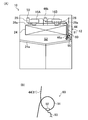
- FIG. 2 is a side cross-sectional view illustrating a schematic configuration of the container refrigeration apparatus according to the first embodiment.
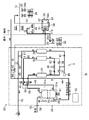
- FIG. 3 is a piping diagram illustrating the configuration of the refrigerant circuit of the container refrigeration apparatus according to the first embodiment.
- FIG. 4 is a piping system diagram showing the configuration of the CA device of the container refrigeration apparatus of the first embodiment, and shows the air flow in the first distribution state.
- FIG. 5 is a piping system diagram showing the configuration of the CA device of the container refrigeration apparatus of the first embodiment, and shows the air flow in the second distribution state.
- FIG. 1 is a perspective view of the container refrigeration apparatus according to Embodiment 1 as viewed from the outside of the warehouse.
- FIG. 2 is a side cross-sectional view illustrating a schematic configuration of the container refrigeration apparatus according to the first embodiment.
- FIG. 3 is a piping diagram illustrating the configuration of the
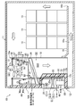
- FIG. 6A is a side view of the container refrigeration apparatus according to Embodiment 1 as viewed from the outside, and FIG. 6B is a partially enlarged view of FIG.
- FIG. 7A is a side view of the container refrigeration apparatus according to Embodiment 1 as viewed from the inside of the box, and FIG. 7B is a partially enlarged view of FIG. 7A.
- FIG. 8 is a diagram illustrating a mode transition state in the normal control according to the first embodiment.
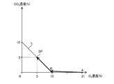
- FIG. 9 is a graph showing a change in the composition of the container air in the container in the concentration adjustment operation in the container refrigeration apparatus of the first embodiment.
- FIG. 10 is a piping diagram illustrating the configuration of the CA device of the container refrigeration apparatus according to the second embodiment.
- FIG. 11 is the schematic perspective view which looked at the container refrigeration apparatus of Embodiment 3 from the warehouse outer side.
- Embodiment 1 of the Invention As shown in FIG.1 and FIG.2, the container refrigeration apparatus (10) is provided in the container (11) used for marine transportation etc., and cools the internal air of this container (11). In the container (11), the plants (15) are stored in a boxed state. The plant (15) breathes by taking in oxygen (O 2 ) in the air and releasing carbon dioxide (CO 2 ). For example, fruits and vegetables such as banana and avocado, vegetables, grains, bulbs, fresh flowers, etc. It is.
- O 2 oxygen
- CO 2 carbon dioxide
- the container (11) is formed in an elongated box shape with one end face opened.
- the container refrigeration apparatus (10) includes a casing (12), a refrigerant circuit (20), and a CA apparatus (Controlled Atmosphere System) (60), and is attached so as to close the open end of the container (11). Yes.
- the casing (12) includes a warehouse outer wall (12a) located on the outside of the container (11) and a cabinet inner wall (12b) located on the inside of the container (11). .
- the outer wall (12a) and the inner wall (12b) are made of, for example, an aluminum alloy.
- the outer wall (12a) is attached to the peripheral edge of the opening of the container (11) so as to close the opening end of the container (11).
- the warehouse outer wall (12a) is formed so that the lower part bulges to the inside of the container (11).
- the inner wall (12b) is placed opposite the outer wall (12a).
- the inner wall (12b) bulges to the inner side corresponding to the lower part of the outer wall (12a).
- a heat insulating material (12c) is provided in the space between the inner wall (12b) and the outer wall (12a).
- the lower part of the casing (12) is formed so as to bulge toward the inner side of the container (11).
- an outside storage space (S1) is formed outside the container (11) at the lower part of the casing (12), and an inside storage space is provided inside the container (11) at the upper part of the casing (12). (S2) is formed.
- first and second service doors (16A, 16B) are closed by first and second service doors (16A, 16B) that can be opened and closed, respectively.
- Each of the first and second service doors (16A, 16B) is constituted by a warehouse outer wall, a warehouse inner wall, and a heat insulating material, like the casing (12).
- a partition plate (18) is arranged inside the container (11).
- This partition plate (18) is comprised by the substantially rectangular-shaped board member, and is standingly arranged in the attitude
- the partition plate (18) divides the interior of the container (11) from the interior storage space (S2).
- a suction port (18a) is formed between the upper end of the partition plate (18) and the ceiling surface in the container (11). The internal air of the container (11) is taken into the internal storage space (S2) through the suction port (18a).
- a partition wall (13) extending in the horizontal direction is provided in the storage space (S2).
- the partition wall (13) is attached to an upper end portion of the partition plate (18), and an opening in which a later-described internal fan (26) is installed is formed.
- the partition wall (13) includes an internal storage space (S2), a primary space (S21) on the suction side of the internal fan (26), and a secondary space (S22) on the outlet side of the internal fan (26).
- the storage space (S2) is vertically divided by the partition wall (13), the primary space on the suction side (S21) is on the upper side, and the secondary space on the outlet side (S22) is on the lower side. Formed on the side.
- a floor board (19) is provided with a gap between the bottom of the container (11).
- a boxed plant (15) is placed on the floor board (19).
- An underfloor channel (19a) is formed between the bottom surface in the container (11) and the floor board (19).
- a gap is provided between the lower end of the partition plate (18) and the bottom surface in the container (11), and communicates with the underfloor channel (19a).
- the refrigerant circuit (20) includes a compressor (21), a condenser (22), an expansion valve (23), and an evaporator (24) in order by a refrigerant pipe (20a). It is a closed circuit configured by connecting.
- the condenser (22) In the vicinity of the condenser (22), it is rotationally driven by an external fan motor (25a), and attracts the air outside the container (11) (outside air) into the external storage space (S1).
- An outside fan (25) to send to 22) is provided.
- the condenser (22) heat is generated between the refrigerant pressurized by the compressor (21) and flowing inside the condenser (22) and the outside air sent to the condenser (22) by the external fan (25). Exchange is performed.
- the external fan (25) is a propeller fan.
- an internal fan that is rotationally driven by an internal fan motor (26a), draws the internal air of the container (11) from the suction port (18a), and blows it out to the evaporator (24)
- Two (26) are provided.
- the pressure is reduced by the expansion valve (23) and flows between the refrigerant flowing in the evaporator (24) and the internal air sent to the evaporator (24) by the internal fan (26). Heat exchange takes place.
- the internal fan (26) has a propeller fan (rotary blade) (27a), a plurality of stationary blades (27b), and a fan housing (27c).
- the propeller fan (27a) is connected to the internal fan motor (26a), is driven to rotate around the rotation axis by the internal fan motor (26a), and blows air in the axial direction.
- the plurality of stationary blades (27b) are provided on the blowing side of the propeller fan (27a), and rectify the air flow blown and swirled from the propeller fan (27a).
- the fan housing (27c) is configured by a cylindrical member having a plurality of stationary blades (27b) attached to the inner peripheral surface, extends to the outer periphery of the propeller fan (27a), and surrounds the outer periphery of the propeller fan (27a).
- the condenser (22) includes a lower first space (S11) and an upper second space (S12) at the central portion in the vertical direction of the external storage space (S1). It is provided to partition.
- the condenser (22) is a so-called fin-and-tube type air heat exchanger, and is provided so that air flows between the lower first space (S11) and the upper second space (S12). It has been.
- the first space (S11) includes the compressor (21), an inverter box (29) containing a drive circuit for driving the compressor (21) at a variable speed, and a CA device (60). And a gas supply device (30).
- an external fan (25) and an electrical component box (17) are provided in the second space (S12).
- the first space (S11) is open to the outside of the container (11), while the second space (S12) is stored so that only the outlet of the outside fan (25) opens to the outside.
- the front surface between the outside (the front surface in FIG. 1) is closed by a plate-like member.
- the evaporator (24) is stored in the secondary space (S22) of the storage space (S2).
- Two internal fans (26) are provided above the evaporator (24) in the internal storage space (S2) in the width direction of the casing (12).
- the CA device (60) includes a gas supply device (30), an exhaust unit (46), a sensor unit (50), a measurement unit (80), and a control unit (55). And adjusting the oxygen concentration and carbon dioxide concentration of the air inside the container (11). Note that “concentration” used in the following description refers to “volume concentration”.
- the gas supply device (30) is a device that generates nitrogen-enriched air having a low oxygen concentration to be supplied into the container (11).
- the gas supply device (30) is configured by VPSA (Vacuum Pressure Swing Adsorption).
- the gas supply apparatus (30) is arrange
- the gas supply device (30) includes an air pump (31), a first directional control valve (32) and a second directional control valve (33), and adsorption for adsorbing nitrogen in the air.
- the gas supply device (30) is configured as one unit by housing the components in the unit case (70), and can be retrofitted to the container refrigeration device (10). Has been.
- the air pump (31) is provided in the unit case (70), and has a first pump mechanism (31a) and a second pump mechanism (31b) that suck, pressurize, and discharge air, respectively.
- the first pump mechanism (31a) and the second pump mechanism (31b) are connected to the drive shaft of the motor (41), and are driven to rotate by the motor (41), thereby sucking, pressurizing and discharging air, respectively. To do.
- the suction port of the first pump mechanism (31a) opens in the unit case (70), and the air inlet (75) of the unit case is provided with a membrane filter (76) having air permeability and waterproofness. Yes. Therefore, the first pump mechanism (31a) removes the outside air from which moisture has been removed when flowing from outside the unit case (70) through the membrane filter (76) provided at the air inlet (75). Inhale and pressurize.
- one end of the discharge passage (42) is connected to the discharge port of the first pump mechanism (31a).
- the other end of the discharge passage (42) branches into two on the downstream side and is connected to the first directional control valve (32) and the second directional control valve (33), respectively.
- the suction passage (43) is connected to the suction port of the second pump mechanism (31b).
- the other end of the suction passage (43) is divided into two on the upstream side, and is connected to each of the first directional control valve (32) and the second directional control valve (33).
- one end of the supply passage (44) is connected to the discharge port of the second pump mechanism (31b).
- the other end of the supply passage (44) opens in the primary space (S21) on the suction side of the internal fan (26) in the internal storage space (S2) of the container (11).
- the supply passage (44) is configured by a flexible tube (hereinafter referred to as supply tube (44)).
- the first pump mechanism (31a) and the second pump mechanism (31b) of the air pump (31) are oilless pumps that do not use lubricating oil. Specifically, when oil is used in the pump of the first pump mechanism (31a), when pressurized air is supplied to the first adsorption cylinder (34) and the second adsorption cylinder (35) and pressurized. Then, the oil contained in the pressurized air is adsorbed by the adsorbent, and the adsorbent adsorption performance deteriorates.
- the oil when oil is used in the pump of the second pump mechanism (31b), the oil is contained in the container (with nitrogen-concentrated air containing nitrogen desorbed from the first adsorption cylinder (34) and the second adsorption cylinder (35)). 11) will be supplied to the warehouse. That is, in this case, nitrogen-enriched air with an oily odor is supplied to the inside of the container (11) in which the plant (15) is loaded.
- the first pump mechanism (31a) and the second pump mechanism (31b) of the air pump (31) are configured by oilless pumps so that the above-described problems can be solved.
- Two air blow fans (48) for cooling the air pump (31) by blowing air toward the air pump (31) are provided on the side of the air pump (31).
- the first directional control valve (32) and the second directional control valve (33) are provided between the air pump (31) and the first adsorption cylinder (34) and the second adsorption cylinder (35) in the air circuit (3).
- the connection state between the air pump (31) and the first suction cylinder (34) and the second suction cylinder (35) is switched between the first connection state and the second connection state. This switching operation is controlled by the control unit (55).
- the first directional control valve (32) includes a discharge passage (42) connected to the discharge port of the first pump mechanism (31a) and a suction port connected to the suction port of the second pump mechanism (31b). It connects to a channel
- the first direction control valve (32) communicates the first adsorption cylinder (34) with the discharge port of the first pump mechanism (31a) and shuts it from the suction port of the second pump mechanism (31b) ( 4) and the second state in which the first adsorption cylinder (34) is communicated with the suction port of the second pump mechanism (31b) and is blocked from the discharge port of the first pump mechanism (31a).
- the second direction control valve (33) includes a discharge passage (42) connected to the discharge port of the first pump mechanism (31a) and a suction passage (43) connected to the suction port of the second pump mechanism (31b). And the top of the second suction cylinder (35).
- the second direction control valve (33) communicates the second adsorption cylinder (35) with the suction port of the second pump mechanism (31b) and shuts it from the discharge port of the first pump mechanism (31a) ( 4) and a second state in which the second adsorption cylinder (35) is communicated with the discharge port of the first pump mechanism (31a) and blocked from the suction port of the second pump mechanism (31b).
- the air circuit (3) causes the discharge port of the first pump mechanism (31a) and the first adsorption cylinder (34).
- the suction port of the second pump mechanism (31b) and the second suction cylinder (35) are switched to the first connection state.
- the first adsorption cylinder (34) performs an adsorption operation for adsorbing nitrogen in the outside air on the adsorbent
- the second adsorption cylinder (35) performs a desorption operation for desorbing nitrogen adsorbed on the adsorbent. Is called.
- both the first directional control valve (32) and the second directional control valve (33) are set to the second state
- the air circuit (3) is connected to the discharge port of the first pump mechanism (31a) and the second adsorption cylinder. (35) is connected and the suction port of the second pump mechanism (31b) and the first suction cylinder (34) are switched to the second connection state.
- the adsorption operation is performed by the second adsorption cylinder (35)
- the desorption operation is performed by the first adsorption cylinder (34).
- the first adsorbing cylinder (34) and the second adsorbing cylinder (35) are cylindrical members filled with an adsorbent inside, and in an upright posture (that is, an posture in which the respective axial directions are vertical directions). is set up.
- the adsorbent filled in the first adsorption cylinder (34) and the second adsorption cylinder (35) has a property of adsorbing nitrogen under pressure and desorbing the adsorbed nitrogen under reduced pressure.
- the adsorbent filled in the first adsorption cylinder (34) and the second adsorption cylinder (35) is, for example, smaller than the molecular diameter of nitrogen molecules (3.0 angstroms) and the molecular diameter of oxygen molecules (2.8 angstroms). ) And a porous zeolite having pores with a larger pore diameter than the above. If the adsorbent is composed of zeolite having such a pore size, nitrogen in the air can be adsorbed.
- the zeolite since the electric field is present in the pores of the zeolite due to the presence of cations and the polarity is generated, the zeolite has the property of adsorbing polar molecules such as water molecules. Therefore, not only nitrogen in the air but also moisture (water vapor) in the air is adsorbed to the adsorbent made of zeolite filled in the first adsorption cylinder (34) and the second adsorption cylinder (35). The moisture adsorbed on the adsorbent is desorbed from the adsorbent together with nitrogen by the desorption operation. Therefore, nitrogen-concentrated air containing moisture is supplied into the container (11), and the humidity inside the container can be increased. Furthermore, since the adsorbent is regenerated, the life of the adsorbent can be extended.
- adsorbing polar molecules such as water molecules. Therefore, not only nitrogen in the air but also moisture (water vapor) in the air is adsorbed to the adsorbent made of ze
- the first adsorption cylinder (34) and the second adsorption cylinder (35) are provided at the lower ends of the first adsorption cylinder (34) and the second adsorption cylinder (35) (the outlet for pressurization and the inlet for decompression).
- One end of an oxygen discharge passage (45) for guiding oxygen-enriched air generated by supplying the external air pressurized by the first pump mechanism (31a) to the outside of the container (11) is connected. Yes.
- One end of the oxygen discharge passage (45) is divided into two and is connected to each of the lower end portions of the first adsorption cylinder (34) and the second adsorption cylinder (35).
- the other end of the oxygen discharge passage (45) is opened outside the gas supply device (30), that is, outside the container (11).
- connection passage connected to the lower end portion of the first adsorption cylinder (34) allows the backflow of air from the oxygen discharge passage (45) to the first adsorption cylinder (34).
- a first check valve (37) is provided to prevent this.
- connection passage connected to the lower end of the second adsorption cylinder (35) has an air flow from the oxygen discharge passage (45) to the second adsorption cylinder (35).
- a second check valve (38) is provided for preventing backflow.
- the two connection passages constituting one end of the oxygen discharge passage (45) are connected via a purge valve (36), and an orifice (62) is provided between the purge valve (36) and each connection passage. Is provided.
- the purge valve (36) concentrates a predetermined amount of oxygen from the pressure-side adsorption cylinder (first adsorption cylinder (34) in FIG. 4) to the pressure-reduction side adsorption cylinder (second adsorption cylinder (35) in FIG. 4). It is used for guiding air and assisting in releasing nitrogen from the adsorbent of the adsorption cylinder (35, 34) on the decompression side.
- the opening / closing operation of the purge valve (36) is controlled by the control unit (55).
- An oxygen tank (39) is provided in the middle of the oxygen discharge passage (45). Between the oxygen tank (39) and the first check valve (37) and the second check valve (38). Is provided with an orifice (61).
- the oxygen tank (39) temporarily stores oxygen-enriched air generated by the first adsorption cylinder (34) and the second adsorption cylinder (35).
- the oxygen-enriched air produced in the first adsorption cylinder (34) and the second adsorption cylinder (35) is temporarily stored in the oxygen tank (39) after being depressurized by the orifice (61).
- a first adsorption cylinder (31a) is provided between the orifice (61) of the oxygen discharge passage (45) and the first check valve (37) and the second check valve (38) by the first pump mechanism (31a). 34) and a pressure sensor (49) for measuring the pressure of the pressurized air supplied to the second adsorption cylinder (35) is connected.
- the air circuit (3) indicates the air circulation state in the air circuit (3), the nitrogen enriched air generated in the first adsorption cylinder (34) and the second adsorption cylinder (35), and the air pump (31).
- the second distribution state in which the air is supplied to the container (11) by the air pump (31), and the second circulation state is supplied to the container (11) by the air pump (31).
- a distribution switching mechanism (65) for switching to a distribution state is provided.
- the flow switching mechanism (65) includes a connection passage (66), a first on-off valve (67), and a second on-off valve (68).
- the connection passage (66) is a passage for connecting the supply passage (44) to the outside portion of the container (11) of the oxygen tank (39) of the oxygen discharge passage (45).
- the first on-off valve (67) is provided on the outer side of the container (11) than the connection portion of the connection passage (66) in the oxygen discharge passage (45), and opens and closes the oxygen discharge passage (45).
- (68) is provided in the connection passage (66).
- the first on-off valve (67) and the second on-off valve (68) are open / close controlled by the control unit (55).
- Air flow state in the air circuit (3) by operating the air pump (31) with the control unit (55) closing the first on-off valve (67) and opening the second on-off valve (68) Is switched to the first distribution state (the state shown in FIG. 4).
- the controller (55) opens the first on-off valve (67) and closes the second on-off valve (68) to operate the air pump (31), thereby The distribution state is switched to the second distribution state (the state shown in FIG. 5).
- the nitrogen-enriched air and the oxygen-enriched air generated in the first adsorption cylinder (34) and the second adsorption cylinder (35) are combined to generate air having the same composition as the outside air, and the air is supplied into the container (11).
- the control unit (55) switches both the first directional control valve (32) and the second directional control valve (33) to the first state shown in FIG.
- the air circuit (3) is configured such that the first adsorption cylinder (34) communicates with the discharge port of the first pump mechanism (31a) and is blocked from the suction port of the second pump mechanism (31b), and the second adsorption The cylinder (35) communicates with the suction port of the second pump mechanism (31b) and enters the first connection state where the cylinder (35) is blocked from the discharge port of the first pump mechanism (31a).
- the first pump mechanism (31a) supplies pressurized outside air to the first adsorption cylinder (34). Nitrogen contained in the air flowing into the first adsorption cylinder (34) is adsorbed by the adsorbent in the first adsorption cylinder (34). Thus, during the first operation, in the first adsorption cylinder (34), the pressurized outside air is supplied from the first pump mechanism (31a), and the nitrogen in the outside air is adsorbed by the adsorbent. Oxygen-enriched air in which the nitrogen concentration is lower than the outside air and the oxygen concentration is higher than the outside air is generated. The oxygen-enriched air flows out from the first adsorption cylinder (34) to the oxygen discharge passage (45).
- the second pump mechanism (31b) sucks air from the second adsorption cylinder (35).
- nitrogen adsorbed on the adsorbent of the second adsorption cylinder (35) is sucked together with air by the second pump mechanism (31b) and desorbed from the adsorbent.
- the second adsorption cylinder (35) is desorbed from the adsorbent by the internal air being sucked by the second pump mechanism (31b) and the nitrogen adsorbed on the adsorbent being desorbed.
- Nitrogen-enriched air containing nitrogen and having a higher nitrogen concentration than the outside air and a lower oxygen concentration than the outside air is generated. The nitrogen-enriched air is sucked into the second pump mechanism (31b), pressurized, and then discharged to the supply passage (44).
- both the first directional control valve (32) and the second directional control valve (33) are switched to the second state opposite to the state shown in FIG. 4 by the control unit (55).
- the air circuit (3) is configured such that the first adsorption cylinder (34) communicates with the suction port of the second pump mechanism (31b) and is blocked from the discharge port of the first pump mechanism (31a), and the second adsorption The cylinder (35) communicates with the discharge port of the first pump mechanism (31a) and enters the second connection state where it is blocked from the suction port of the second pump mechanism (31b).
- the first pump mechanism (31a) supplies pressurized outside air to the second adsorption cylinder (35). Nitrogen contained in the air flowing into the second adsorption cylinder (35) is adsorbed by the adsorbent of the second adsorption cylinder (35).
- pressurized external air is supplied from the first pump mechanism (31a), and nitrogen in the external air is adsorbed by the adsorbent, Oxygen-enriched air in which the nitrogen concentration is lower than the outside air and the oxygen concentration is higher than the outside air is generated.
- the oxygen-enriched air flows out from the second adsorption cylinder (35) to the oxygen discharge passage (45).
- the second pump mechanism (31b) sucks air from the first adsorption cylinder (34).
- nitrogen adsorbed on the adsorbent of the first adsorption cylinder (34) is sucked together with air by the second pump mechanism (31b) and desorbed from the adsorbent.
- the first adsorption cylinder (34) is desorbed from the adsorbent by the internal air sucked by the second pump mechanism (31b) and the nitrogen adsorbed on the adsorbent is desorbed.
- Nitrogen-enriched air containing nitrogen and having a higher nitrogen concentration than the outside air and a lower oxygen concentration than the outside air is generated. The nitrogen-enriched air is sucked into the second pump mechanism (31b), pressurized, and then discharged to the supply passage (44).
- nitrogen enriched air and oxygen enriched air are generated in the air circuit (3) by alternately repeating the first operation and the second operation.
- the flow state of the air in the air circuit (3) is switched between the first flow state and the second flow state by the flow switching mechanism (65).
- the air circuit (3) is operated by operating the air pump (31) with the first opening / closing valve (67) closed and the second opening / closing valve (68) opened by the control unit (55). Is switched to the first distribution state shown in FIG. In the first flow state, as in the conventional gas supply device (30), the oxygen-enriched air generated in the first adsorption cylinder (34) and the second adsorption cylinder (35) is the first of the air pump (31).
- the concentrated air is supplied into the container (11) through the supply passage (44) by the pressurizing force of the second pump mechanism (31b) of the air pump (31).
- the nitrogen-enriched air generated in the first adsorption cylinder (34) and the second adsorption cylinder (35) is caused by the applied pressure of the second pump mechanism (31b) of the air pump (31). Gas supply operation to supply the container (11) is performed.
- the controller (55) opens the first on-off valve (67) and closes the second on-off valve (68) to operate the air pump (31), thereby
- the distribution state is switched to the second distribution state shown in FIG.
- the first adsorption cylinder (34) and the second adsorption cylinder (35) and the outside of the gas supply device (30) (outside the chamber) are blocked, while the oxygen discharge passage (45) and the supply are supplied.
- the passage (44) is connected to the passage (66).
- the oxygen-enriched air generated in the first adsorption cylinder (34) and the second adsorption cylinder (35) is supplied to the oxygen discharge passage (45) by the applied pressure of the first pump mechanism (31a) of the air pump (31). Is pushed into the supply passage (44) through the connection passage (66). In the supply passage (44), the nitrogen-enriched air generated in the first adsorption cylinder (34) and the second adsorption cylinder (35) by the pressure of the second pump mechanism (31b) of the air pump (31) is stored in the container. It flows toward the inside of (11).
- the oxygen-enriched air merges with the flow of nitrogen-enriched air, and air having the same composition as the outside air is generated.
- the air having the same composition as the outside air generated in the supply passage (44) in this way is supplied into the container (11) by the pressurizing force of the second pump mechanism (31b) of the air pump (31).
- the air having the same composition as the outside air in the air circuit (3) is converted into the inside of the container (11) by the pressurizing force of the second pump mechanism (31b) of the air pump (31).
- the outside air introduction operation is performed.
- the exhaust part (46) has an exhaust passage connecting the storage space (S2) in the warehouse and the outside of the warehouse, and an exhaust valve (46b) connected to the exhaust passage (46a). ing.
- the exhaust passage (46a) is constituted by a flexible tube (hereinafter referred to as an exhaust tube (46a)).
- the exhaust tube (46a) is inserted into a through-hole (12d) that connects the storage space (S2) formed in the casing (12) and the second space (S12) of the storage space (S1) outside the storage, It penetrates the casing (12).
- the exhaust tube (46a) has an inlet end opened in the secondary space (S22) on the outlet side of the internal fan (26), and an outlet end in the second space (S12) of the external storage space (S1). It is open. More specifically, the outlet end of the exhaust tube (46a) opens in the second space (S12) in the vicinity of the motor (25a) disposed on the suction side of the external fan (25) made of a propeller fan. It is provided to do.
- the second space (S12) is closed so that only the outlet of the outside fan (25) opens to the outside.
- the second space (S12) becomes a suction side space into which air is sucked by the external fan (25).
- the outlet end of the exhaust tube (46a) is provided in the space on the suction side of the external fan (25).
- the exhaust valve (46b) is provided on the inner side of the exhaust tube (46a), and allows the air to flow in the exhaust tube (46a) and the air flow in the exhaust tube (46a). It is comprised by the solenoid valve which switches to the closed state which interrupts
- the opening / closing operation of the exhaust valve (46b) is controlled by the control unit (55).
- the exhaust unit (46) opens the exhaust valve (46b) by the control unit (55) during the operation of the external fan (25), thereby allowing the internal storage space (S2) ) (Exhaust air) is exhausted to the outside.
- the pressure in the second space (S12) on the suction side of the outside fan (25) becomes lower than the pressure (atmospheric pressure) in the outside space.
- the pressure drop of the pressure in the second space (S12) on the suction side of the outside fan (25) becomes larger.
- the pressure inside the container (11) may be lower than the pressure (atmospheric pressure) in the outside space.
- the air volume of the external fan (25) the pressure in the secondary space (S22) on the outlet side of the internal fan (26) where the inlet end of the exhaust tube (46a) is easily opened can be reduced. It can be made higher than the pressure (atmospheric pressure) in the external space where the outlet end of the exhaust tube (46a) opens.
- the sensor unit (50) is provided in the secondary space (S22) on the outlet side of the internal fan (26) in the internal storage space (S2).
- the sensor unit (50) includes an oxygen sensor (51), a carbon dioxide sensor (52), a fixed plate (53), a membrane filter (54), a connecting pipe (56), and an exhaust pipe (57).
- the oxygen sensor (51) has an oxygen sensor box (51a) in which a galvanic cell type sensor is accommodated.
- the oxygen sensor (51) measures the oxygen concentration in the gas in the oxygen sensor box (51a) by measuring the value of the current flowing through the electrolyte solution of the galvanic cell type sensor.
- the outer surface of the oxygen sensor box (51a) is fixed to the fixed plate (53).
- An opening is formed in the outer surface of the oxygen sensor box (51a) opposite to the surface fixed to the fixing plate (53), and a membrane filter (54) having air permeability and waterproofness is formed in the opening. ) Is attached.
- a branch pipe (81) of a measurement unit (80) described later is connected to the lower surface of the oxygen sensor box (51a) via a connector (pipe joint).
- one end of the connecting pipe (56) is connected to one side surface of the oxygen sensor box (51a) via a connector.
- the carbon dioxide sensor (52) has a carbon dioxide sensor box (52a), radiates infrared rays to the gas in the carbon dioxide sensor box (52a), and measures the absorption amount of infrared rays having a wavelength specific to carbon dioxide. Is a non-dispersive infrared (NDIR) sensor that measures the concentration of carbon dioxide in a gas.
- the other end of the connecting pipe (56) is connected to one side surface of the carbon dioxide sensor box (52a) via a connector.
- One end of the exhaust pipe (57) is connected to the other side surface of the carbon dioxide sensor box (52a) via a connector.
- the fixing plate (53) is fixed to the casing (12) with the oxygen sensor (51) and the carbon dioxide sensor (52) attached.
- the communication pipe (56) is connected to the side surface of the oxygen sensor box (51a) and the side surface of the carbon dioxide sensor box (52a), and the internal space of the oxygen sensor box (51a) and the carbon dioxide sensor box ( It communicates with the internal space of 52a).
- one end of the exhaust pipe (57) is connected to the other side surface of the carbon dioxide sensor box (52a), and the other end is opened in the vicinity of the suction port of the internal fan (26). That is, the exhaust pipe (57) communicates the internal space of the carbon dioxide sensor box (52a) with the primary space (S21) of the storage space (S2).
- the secondary space (S22) and the primary space (S21) of the storage space (S2) are the membrane filter (54), the internal space of the oxygen sensor box (51a), the connecting pipe (56), The carbon dioxide sensor box (52a) communicates with the internal space and the air passage (58) formed by the exhaust pipe (57). Therefore, during operation of the internal fan (26), the pressure in the primary space (S21) becomes lower than the pressure in the secondary space (S22).
- the air passage (58) connected to the carbon sensor (52) the in-compartment air flows from the secondary space (S22) side to the primary space (S21) side. In this way, the internal air passes through the oxygen sensor (51) and the carbon dioxide sensor (52) in order, the oxygen concentration of the internal air is measured by the oxygen sensor (51), and the carbon dioxide sensor (52) The carbon dioxide concentration of the internal air is measured.
- the measurement unit (80) includes a branch pipe (81) and a measurement on-off valve (82), and branches part of the nitrogen-enriched air generated in the gas supply device (30) and flowing through the supply passage (44). And led to the oxygen sensor (51).
- the branch pipe (81) has one end connected to the supply passage (44) and the other end connected to the oxygen sensor box (51a) of the oxygen sensor (51). With such a configuration, the branch pipe (81) makes the supply passage (44) communicate with the internal space of the oxygen sensor box (51a).
- the branch pipe (81) is provided so as to branch from the supply passage (44) in the unit case (70) and extend inside and outside the unit case.
- the branch pipe (81) is configured by a flexible tube (hereinafter referred to as a measurement tube (81)).
- the measurement on-off valve (82) is provided inside the unit case of the branch pipe (81).
- the on-off valve for measurement (82) is an electromagnetic valve that switches between an open state allowing the flow of nitrogen-enriched air in the branch pipe (81) and a closed state blocking the flow of the nitrogen-enriched air in the branch pipe (81). It is configured.
- the opening / closing operation of the measurement on-off valve (82) is controlled by the control unit (55). Although details will be described later, the measurement on-off valve (82) is opened only when an air supply measurement operation described later is executed, and is closed in other modes.
- the control unit (55) is configured to execute a concentration adjustment operation for setting the oxygen concentration and the carbon dioxide concentration of the air inside the container (11) to desired concentrations. Specifically, the control unit (55) determines the composition (oxygen concentration and carbon dioxide concentration) of the air in the container (11) based on the measurement results of the oxygen sensor (51) and the carbon dioxide sensor (52). The operations of the gas supply device (30) and the exhaust unit (46) are controlled so as to obtain a desired composition (for example, oxygen concentration 5%, carbon dioxide concentration 5%). As shown in FIG. 8, in the present embodiment, the control unit (55) is configured to perform the concentration adjustment operation by executing the start-up control and the normal control. The control unit (55) performs normal control after completion of predetermined start-up control, and is configured to perform an oxygen concentration reduction mode and an air composition adjustment mode in the normal control.
- control unit (55) controls the operation of the measurement on-off valve (82) in accordance with a command from the user or periodically, and controls the oxygen concentration of the nitrogen-enriched air generated in the gas supply device (30). It is configured to perform an air supply measurement operation to measure.
- control unit (55) controls the operations of the air pump (31), the first on-off valve (67), and the second on-off valve (68) in accordance with a command from the user or periodically, so that the container (11)
- the supply tube (44), the measurement tube (81) and the exhaust tube (46a) are formed in the casing (12). It is inserted through the through-hole (12d), and is provided across the interior and exterior of the casing (12).
- the supply tube (44) and the measurement tube (81) are also inserted through the through hole (12d) of the casing (12) and penetrate the casing (12), like the exhaust tube (46a).
- Each of the supply tube (44) and the measurement tube (81) has an inlet end connected to the air circuit (3) of the gas supply device (30) and an outlet end connected to the secondary space (S2) in the storage space (S2). Open in S22).
- Each has a drainage structure (90) for discharging the wastewater.
- the drainage structure (90) provided in the three tubes (44, 81, 46a) includes a trap portion (91), a pipe joint (92), and And a drain tube (93).
- the trap portion (91) is formed by bending a portion of each flexible tube (44, 81, 46a) in an annular shape and bundling the portion where the tubes (44, 81, 46a) overlap with a binding band or the like. ing.
- the pipe joint (92) is attached to a part other than the binding part of the trap part (91).
- One end of the drain tube (93) is connected to the pipe joint (92), and the other end (not shown) is opened outside the casing (12).
- each tube (44, 81, 46a) By arranging the drainage structure (90) having such a configuration so that the pipe joint (92) is positioned at the lowermost side in the trap portion (91), the inside of each tube (44, 81, 46a) When the generated dew condensation water flows through the trap part (91) together with air, it is collected near the pipe joint (92) located at the lowermost side of the trap part (91) by gravity, and passes through the drain tube (93). It is discharged outside the casing (12).
- the exhaust tube (46a) is provided with a drainage structure (90) in the outside portion disposed in the outside storage space (S1).
- the drainage structure (90) is located near the through hole (12d) that communicates the inside and outside of the casing (12) in the outside portion of the exhaust tube (46a). It is formed at the position immediately after exiting from the hole (12d) to the outside of the warehouse.
- the dew condensation water generated inside the exhaust tube (46a) can be captured near the location where the dew condensation water is generated and discharged to the outside. Further, as shown in FIG. 6A, the outside portion of the exhaust tube (46a) descends from the trap portion (91) toward the outlet end opened on the suction side of the outside fan (25). It is arranged. Therefore, even when seawater reaches near the outlet end of the exhaust tube (46a), it does not flow into the cabinet through the exhaust tube (46a) against gravity.
- each tube (44,81) is provided with the drainage structure (90) in the interior part arrange
- the drainage structure (90) is located near the through hole (12d) that communicates the inside of the casing (12) and the outside of the casing (12) in the inside portion of each tube (44,81) (in this embodiment, It is formed at the position immediately after entering the inside of the warehouse from the through hole (12d).
- the outlet end of each tube (44, 81) is provided in the secondary space (S22) so as to open on the upper surface of the drain pan (24a) that receives the dew condensation water generated in the evaporator (24).
- a cooling operation for cooling the internal air of the container (11) is executed by the unit controller (100) shown in FIG.
- the operation of the compressor (21), the expansion valve (23), the external fan (25), and the internal fan (26) is performed based on the measurement result of a temperature sensor (not shown) by the unit controller (100).
- the temperature of the internal air is controlled to a desired target temperature.
- the refrigerant circuit (20) the refrigerant circulates to perform a vapor compression refrigeration cycle.
- the internal air of the container (11) guided to the internal storage space (S2) by the internal fan (26) flows through the evaporator (24) when passing through the evaporator (24). Cooled by the refrigerant.
- the in-compartment air cooled in the evaporator (24) is blown out again from the outlet (18b) into the container (11) through the underfloor channel (19a). Thereby, the internal air of the container (11) is cooled.
- the CA (60) causes the controller (55) shown in FIG. 4 to store the container (11) based on the measurement results of the oxygen sensor (51) and the carbon dioxide sensor (52).
- a concentration adjustment operation is performed to adjust the composition of the internal air (oxygen concentration and carbon dioxide concentration) to a desired composition (for example, oxygen concentration 5%, carbon dioxide concentration 5%).
- the control unit (55) performs the concentration adjustment operation by executing the start-up control and the normal control. Further, in the normal control, the control unit (55) executes the oxygen concentration reduction mode and the air composition adjustment mode to change the oxygen concentration and carbon dioxide concentration of the air in the container (11) to a predetermined target concentration SP. Adjust to.
- the control unit (55) controls the measurement on-off valve (82) to be closed.
- the control unit (55) communicates with the unit control unit (100), and the unit control unit (100) rotates the internal fan (26). Accordingly, the internal air is supplied to the oxygen sensor (51) and the carbon dioxide sensor (52) by the internal fan (26), and the oxygen concentration and the carbon dioxide concentration of the internal air are measured. .
- the control unit (55) executes the oxygen concentration reduction mode in the normal control after the start-up control is completed.
- the control unit (55) The lowering mode is terminated and the air composition adjustment mode is executed.
- the oxygen concentration of the air in the container (11) measured by the oxygen sensor (51) is set to a target oxygen concentration SPO 2 (5% in this embodiment) and a predetermined concentration V (in this embodiment). , 1.0%) or more (6.0% in this embodiment), the control unit (55) ends the air composition adjustment mode and returns to the oxygen concentration reduction mode.
- the oxygen concentration reduction mode and the air composition adjustment mode in the normal control will be described in detail.
- the control unit (55) switches the air circuit (3) to the first flow state, and in the air circuit (3), nitrogen-concentrated air (nitrogen concentration 90%, oxygen concentration 10%) is supplied.
- chamber of a container (11) is performed.
- the control unit (55) controls the exhaust valve (46b) of the exhaust unit (46) to open to perform an exhaust operation, and nitrogen enriched air is brought into the container (11) by the gas supply operation.
- the air in the cabinet is discharged to the outside as much as the supplied amount. With such a gas supply operation and an exhaust operation, the air in the warehouse is replaced with nitrogen-enriched air, so that the oxygen concentration of the air in the warehouse decreases (point A ⁇ point B in FIG. 9).
- Control unit (55) becomes the target density sum total value is the sum of the target oxygen concentration SPO 2 and the target carbon dioxide concentration SPCO 2 which is the sum of oxygen and carbon dioxide concentrations in the air inside the container (11) (Up to point B in FIG. 9), the gas supply operation and the exhaust operation are stopped.
- the oxygen concentration decreases and the carbon dioxide concentration increases. That is, by stopping the gas supply operation and the exhaust operation at an arbitrary point on the straight line L, thereafter, the composition of the air in the container (11) can be targeted only by using the respiration of the plant (15). It can be adjusted to the composition.
- the control unit (55) ends the oxygen concentration reduction mode and starts the air composition adjustment mode.
- the control unit (55) has a predetermined concentration X (0.5% in the present embodiment) where the oxygen concentration of the internal air is higher than the target oxygen concentration SPO 2 (5% in the present embodiment). If the lower limit value (4.5% in the present embodiment) is lower than the lower limit value, oxygen concentration increase control is performed to increase the oxygen concentration of the internal air.
- the control unit (55) switches the air circuit (3) to the second flow state, and air (nitrogen-enriched air and oxygen-enriched air having the same composition as the outside air in the air circuit (3) is used.
- air nitrogen-enriched air and oxygen-enriched air having the same composition as the outside air in the air circuit (3) is used.
- the outside air introduction operation for supplying the air generated by mixing) into the container (11) is performed.
- the control unit (55) controls the exhaust valve (46b) of the exhaust unit (46) to be in an open state to perform an exhaust operation.
- the air in the cabinet is exhausted to the outside by the amount supplied into the cabinet.
- the control unit (55) has a value (this embodiment) in which the oxygen concentration of the internal air is higher by a predetermined concentration X (0.5% in this embodiment) than the target oxygen concentration SPO 2 (5% in this embodiment). In the embodiment, when it becomes 5.5%) or more, the outside air introduction operation and the exhaust operation are stopped, and the oxygen concentration increase control is ended.
- the control unit (55) is configured such that the carbon dioxide concentration of the internal air is a predetermined concentration Y (0 in the present embodiment) than the target carbon dioxide concentration SPCO 2 (5% in the present embodiment). .5%) higher than the upper limit (5.5% in this embodiment) or more, the carbon dioxide concentration lowering control is performed to reduce the carbon dioxide concentration of the air in the warehouse.
- the control unit (55) switches the air circuit (3) to the first flow state, and in the air circuit (3), nitrogen concentrated air (nitrogen concentration 90). %, Oxygen concentration 10%) is generated and supplied into the container (11).
- the control unit (55) controls the exhaust valve (46b) of the exhaust unit (46) to open to perform an exhaust operation, and nitrogen enriched air is brought into the container (11) by the gas supply operation.
- the air in the cabinet is discharged to the outside as much as the supplied amount. By such gas supply operation and exhaust operation, the internal air is replaced with nitrogen-enriched air, so that the carbon dioxide concentration in the internal air of the container (11) is lowered.
- the control unit (55) has a value in which the carbon dioxide concentration of the internal air is lower by a predetermined concentration Y (0.5% in this embodiment) than the target carbon dioxide concentration SPCO 2 (5% in this embodiment). When it is less than 4.5% in this embodiment, the gas supply operation and the exhaust operation are stopped, and the carbon dioxide concentration reduction control is terminated.
- the air circuit (3) is switched to the second flow state, and the air circuit (3) has the same composition as the outside air (nitrogen-enriched air and oxygen-enriched air).
- the outside air may be introduced into the container (11) and supplied to the inside of the container (11).
- a control part (55) performs the air supply measurement operation
- the air supply measurement operation is performed in parallel when the internal fan (26) stops during the gas supply operation such as the above-described concentration adjustment operation or trial operation.
- the composition (oxygen concentration, nitrogen concentration) of the nitrogen-enriched air generated in the gas supply device (30) is desired by measuring the oxygen concentration of the nitrogen-enriched air generated in the gas supply device (30). (For example, nitrogen concentration 90%, oxygen concentration 10%) can be confirmed.
- the outer end of the exhaust tube (exhaust passage) (46a) is opened on the suction side of the external fan (25) in the external storage space (S1). I was allowed to. Therefore, the rotation of the outside fan (25) causes the suction side pressure of the outside fan (25) where the outside end of the exhaust tube (46a) opens to the inside side of the exhaust tube (46a). It can be made lower than the pressure on the outlet side of the internal fan (26) whose end is open. Therefore, even when the pressure inside the container (11) is lower than the pressure outside the container, the pressure in the space where the inner end of the exhaust tube (46a) opens by the outside fan (25) is reduced.
- all of the outside of the exhaust tube (46a) is stored in the second space (S1) in the external storage space (S1) located downstream of the condenser (22) of the outside air flow. S12).
- the internal air flowing through the exhaust tube (46a) is externally heated by the refrigerant when passing through the condenser (22) in the entire external portion of the exhaust tube (46a). Warmed by outside air. Even when the outside air temperature is extremely low, it is possible to suppress the formation of condensation over the entire outside of the exhaust tube (46a). Therefore, the dew condensation water generated inside the exhaust tube (46a) is blown out from the end together with the inside air, and is not blown to the outside fan (25) or the condenser (22). Corrosion of the external fan (25) and condenser (22) due to adhesion can be prevented.
- the exhaust tube (46a) is provided with the drainage structure (90) for discharging the dew condensation water to the outside of the chamber where dew condensation may occur inside. Therefore, the dew condensation water generated inside the exhaust tube (46a) is discharged to the outside through the drainage structure (90), so that the dew condensation water can be prevented from flowing into the warehouse.
- the drainage structure (90) includes a trap part (91) constituted by a part of the exhaust tube (46a) and a drain tube (91) connected to the trap part (91). 93).
- the drainage structure (90) is provided at a position near the through hole (12d) for the outside of the warehouse where condensation may occur inside the exhaust tube (46a). Condensed water generated inside the exhaust tube (46a) can be captured near the location where the condensed water is generated and discharged to the outside.
- Embodiment 2 of the present invention As shown in FIG. 10, the second embodiment is obtained by changing the configuration of the exhaust section (46) in the container refrigeration apparatus (10) of the first embodiment.
- the exhaust valve (46b) constituted by the electromagnetic valve in the first embodiment is constituted by a check valve which opens in the second embodiment when the pressure difference between both ends becomes a predetermined value or more.
- the exhaust valve (46b) consisting of this check valve allows only air flow from the inside to the outside of the chamber in the exhaust tube (46a) that penetrates the casing (12) from the inside to the outside. It is provided on the inner side of the exhaust tube (46a) so as to prevent circulation.
- the exhaust valve (46b) by performing the gas supply operation and the outside air introduction operation by the exhaust valve (46b) including such a check valve, the pressure inside the container (11) is reduced by the outside fan (25).
- the exhaust valve (46b) opens and the air in the container (11) opens the exhaust tube (46a). It is discharged out of the warehouse.
- the exhaust valve (46b) is not controlled by the control unit (55), and the second space (S12) inside the container (11) and outside the container (S12). It automatically opens and closes according to the pressure difference with the pressure of) to stabilize the pressure inside the container (11) to a pressure value that is higher than the pressure in the second space (S12) outside the container by a predetermined pressure value. Can be made. As a result, since the gas supply operation and the outside air introduction operation can be stabilized, the composition (oxygen concentration and carbon dioxide concentration) of the internal air of the container (11) can be easily adjusted, and can be performed with high accuracy. .
- Embodiment 3 of the present invention As shown in FIG. 11, the third embodiment is the same as the first and second embodiments, except that the condenser (22), the external fan (25), the electrical component box (17), and the inverter in the external storage space (S1). The positional relationship with the box (29) is changed.
- the condenser (22) formed so as to extend in a straight line in the horizontal direction is replaced by three heat exchange surfaces (bending positions) 22a, 22b, 22c) is changed to a condenser (22) formed into a U-shape, and this condenser (22) is placed in the upper central part of the external storage space (S1) at each heat exchange surface ( 22a, 22b, and 22c) are provided so as to be located on the upper side, the right side, and the lower side in FIG.
- the external fan (25) provided above the condenser (22) in the first and second embodiments is provided inside the U-shaped condenser (22) in the third embodiment. .
- the electrical component box (17) provided above the condenser (22) in the first and second embodiments is provided on the left side of the condenser (22) in FIG. 11 in the third embodiment.
- the inverter box (29) provided below the condenser (22) in the first and second embodiments is provided on the right side in FIG. 11 of the condenser (22) in the third embodiment.
- the outside storage space (S1) is partitioned by the condenser (22) into a first space (S11) on the upstream side of the outside air flow and a second space (S12) on the downstream side. Yes. Therefore, the outside fan (25) arranged inside the condenser (22) is provided in the second space (S12). Also in the third embodiment, the first space (S11) is opened to the outside of the container (11), while the second space (S12) has only the outlet of the outside fan (25).
- the front surface (front surface in FIG. 11) and the left side surface between the outside and the outside of the warehouse are closed by a plate-like member so as to open to the outside of the warehouse.
- the left side surface of the second space (S12) is closed by the right side surface of the electrical component box (17).
- illustration is abbreviate
- the edge part of the warehouse outer side of an exhaust passage (46a) is opened in 2nd space (S12).
- the outside fan (25) provided in the second space (S12) is open on the back side in FIG. 11 and inside the U-shaped condenser (22).
- the trap part (91) of the drainage structure (90) is formed by bending a part of each flexible tube (44, 81, 46a) in an annular shape and bundling it with a binding band or the like. It was.
- the trap part (91) may have any shape as long as the condensed water can be temporarily stored, and may be formed in, for example, a U shape or an S shape.
- the exhaust tube (46a) it is not necessary to provide all of the exhaust tube (46a) outside the warehouse in the second space (S12), at least partly May be provided in the second space (S12).
- the internal air flowing through the exhaust tube (46a) passes through the condenser (22). Since it is warmed by the outside air heated, the occurrence of condensation can be suppressed.
- one air pump (31) has the first pump mechanism (31a) and the second pump mechanism (31b).
- the first pump mechanism (31a) and the second pump mechanism (31b) ) May be constituted by two individual air pumps.
- the first adsorption unit and the second adsorption unit are configured to perform adsorption and desorption of nitrogen using one adsorption cylinder.
- the number is not limited to one.
- each suction part may be constituted by three suction cylinders, and a total of six suction cylinders may be used.
- CA the container refrigeration apparatus (10) provided in the container (11) for marine transportation
- CA concerning this invention
- the use of the device (60) is not limited to this.
- the CA device (60) according to the present invention can be used for adjusting the composition of air in a warehouse, for example, a container for land transportation, a simple refrigerated warehouse, a warehouse at room temperature, in addition to a container for sea transportation.
- the present invention is useful for a container refrigeration apparatus that cools the internal air of a container and adjusts the composition of the internal air of the container.
Landscapes
- Engineering & Computer Science (AREA)
- Chemical & Material Sciences (AREA)
- Mechanical Engineering (AREA)
- Combustion & Propulsion (AREA)
- Physics & Mathematics (AREA)
- Thermal Sciences (AREA)
- General Engineering & Computer Science (AREA)
- Life Sciences & Earth Sciences (AREA)
- General Chemical & Material Sciences (AREA)
- Chemical Kinetics & Catalysis (AREA)
- Wood Science & Technology (AREA)
- Zoology (AREA)
- Food Science & Technology (AREA)
- Polymers & Plastics (AREA)
- Cold Air Circulating Systems And Constructional Details In Refrigerators (AREA)
- Devices That Are Associated With Refrigeration Equipment (AREA)
Abstract
L'invention concerne un appareil de réfrigération pour conteneur, dans lequel est placé un dispositif de conditionnement d'air interne qui ajuste la composition de l'air interne, qui permet d'évacuer l'air interne même lorsque la pression à l'intérieur du conteneur est inférieure à celle à l'extérieur du conteneur. L'appareil de réfrigération pour conteneurs comprend : un boîtier (12) qui forme un espace de stockage externe (S1) qui est en communication avec l'extérieur du conteneur (11) et un espace de stockage interne (S2) qui est en communication avec l'intérieur du conteneur (11) ; un circuit de fluide frigorigène (20) ; un ventilateur externe (25) ; un ventilateur interne (26) ; un dispositif de conditionnement d'air interne (60) dont un trajet d'échappement (46a) relie un dispositif d'alimentation en gaz (30), un côté de soufflage du ventilateur interne (26) dans l'espace de stockage interne (S2) et l'espace de stockage externe (S1), et qui ajuste la composition de l'air à l'intérieur du conteneur (11), la partie extrémité sur le côté externe du trajet d'échappement (46a) étant ouverte sur le côté aspiration du ventilateur externe (25) de l'espace de stockage externe (S1).
Priority Applications (5)
| Application Number | Priority Date | Filing Date | Title |
|---|---|---|---|
| CN201680010614.5A CN107250694B (zh) | 2015-02-27 | 2016-02-25 | 集装箱用制冷装置 |
| SG11201706658QA SG11201706658QA (en) | 2015-02-27 | 2016-02-25 | Refrigeration apparatus for containers |
| EP16755017.7A EP3258193B1 (fr) | 2015-02-27 | 2016-02-25 | Appareil de réfrigération pour conteneur |
| DK16755017.7T DK3258193T3 (da) | 2015-02-27 | 2016-02-25 | Køleapparat til containere |
| US15/552,425 US11015855B2 (en) | 2015-02-27 | 2016-02-25 | Refrigeration apparatus for containers |
Applications Claiming Priority (2)
| Application Number | Priority Date | Filing Date | Title |
|---|---|---|---|
| JP2015039244 | 2015-02-27 | ||
| JP2015-039244 | 2015-02-27 |
Publications (1)
| Publication Number | Publication Date |
|---|---|
| WO2016136267A1 true WO2016136267A1 (fr) | 2016-09-01 |
Family
ID=56788306
Family Applications (1)
| Application Number | Title | Priority Date | Filing Date |
|---|---|---|---|
| PCT/JP2016/001026 Ceased WO2016136267A1 (fr) | 2015-02-27 | 2016-02-25 | Appareil de réfrigération pour conteneur |
Country Status (7)
| Country | Link |
|---|---|
| US (1) | US11015855B2 (fr) |
| EP (1) | EP3258193B1 (fr) |
| JP (1) | JP6056997B2 (fr) |
| CN (1) | CN107250694B (fr) |
| DK (1) | DK3258193T3 (fr) |
| SG (1) | SG11201706658QA (fr) |
| WO (1) | WO2016136267A1 (fr) |
Cited By (1)
| Publication number | Priority date | Publication date | Assignee | Title |
|---|---|---|---|---|
| CN110118460A (zh) * | 2019-04-30 | 2019-08-13 | 茂华中北建设工程有限公司 | 一种集装箱式冷库制冷装置 |
Families Citing this family (18)
| Publication number | Priority date | Publication date | Assignee | Title |
|---|---|---|---|---|
| US20170108263A1 (en) * | 2014-06-11 | 2017-04-20 | Thermo King Corporation | Air supply system and method |
| SG11201706658QA (en) * | 2015-02-27 | 2017-09-28 | Daikin Ind Ltd | Refrigeration apparatus for containers |
| SE541965C2 (en) * | 2016-07-12 | 2020-01-14 | Es Energy Save Holding Ab | Heat pump apparatus module |
| CN106524630A (zh) * | 2016-12-09 | 2017-03-22 | 青岛海尔股份有限公司 | 冰箱及用于冰箱的储物容器 |
| US11051525B2 (en) | 2017-09-19 | 2021-07-06 | Daikin Industries, Ltd. | Gas supply device, interior air adjustment device, and container refrigeration device |
| US11835270B1 (en) | 2018-06-22 | 2023-12-05 | Booz Allen Hamilton Inc. | Thermal management systems |
| CN112334340B (zh) * | 2018-10-03 | 2024-11-26 | 开利公司 | 发生器移动控制 |
| US11293673B1 (en) | 2018-11-01 | 2022-04-05 | Booz Allen Hamilton Inc. | Thermal management systems |
| US11486607B1 (en) | 2018-11-01 | 2022-11-01 | Booz Allen Hamilton Inc. | Thermal management systems for extended operation |
| US11168925B1 (en) | 2018-11-01 | 2021-11-09 | Booz Allen Hamilton Inc. | Thermal management systems |
| US11835271B1 (en) | 2019-03-05 | 2023-12-05 | Booz Allen Hamilton Inc. | Thermal management systems |
| US11561033B1 (en) | 2019-06-18 | 2023-01-24 | Booz Allen Hamilton Inc. | Thermal management systems |
| BR112022006121A2 (pt) * | 2019-09-30 | 2022-06-21 | Greenlifetech Corp | Sistemas para remover oxigênio de um recipiente e método para remover oxigênio de um recipiente |
| US11752837B1 (en) | 2019-11-15 | 2023-09-12 | Booz Allen Hamilton Inc. | Processing vapor exhausted by thermal management systems |
| CN112303999A (zh) * | 2019-11-29 | 2021-02-02 | 北京丹纳斯科技有限公司 | 一种有氧呼吸类蔬果保鲜仓储装置 |
| US11561030B1 (en) | 2020-06-15 | 2023-01-24 | Booz Allen Hamilton Inc. | Thermal management systems |
| US20240138446A1 (en) * | 2021-01-21 | 2024-05-02 | Bruce B. Roesner | Food preservation system |
| US12581613B2 (en) * | 2023-12-01 | 2026-03-17 | Ua Sun Co., Ltd. | Apparatus of improving durability based on dehumidification device |
Citations (9)
| Publication number | Priority date | Publication date | Assignee | Title |
|---|---|---|---|---|
| JPS6110143Y2 (fr) * | 1981-02-06 | 1986-04-01 | ||
| JPS6372483U (fr) * | 1986-10-31 | 1988-05-14 | ||
| JPH07190602A (ja) * | 1993-11-30 | 1995-07-28 | Samsung Electronics Co Ltd | 冷蔵庫の圧力平衡装置 |
| JPH08167A (ja) * | 1994-06-15 | 1996-01-09 | Carrier Corp | 冷凍コンテナ用庫内環境制御システム |
| JPH09105577A (ja) * | 1995-06-28 | 1997-04-22 | Boc Group Plc:The | コンテナの中の雰囲気制御 |
| JP2002274608A (ja) * | 2001-03-21 | 2002-09-25 | Ube Ind Ltd | 庫内の湿度及び/又は酸素ガス濃度を制御可能な収納庫 |
| JP2006052913A (ja) * | 2004-08-16 | 2006-02-23 | Mitsubishi Heavy Ind Ltd | 輸送コンテナ用の冷却装置 |
| JP2007509309A (ja) * | 2003-10-20 | 2007-04-12 | キャリア コーポレイション | 外気孔位置監視システム |
| JP2012136287A (ja) * | 2010-12-06 | 2012-07-19 | Shin Etsu Polymer Co Ltd | リーファーコンテナ |
Family Cites Families (92)
| Publication number | Priority date | Publication date | Assignee | Title |
|---|---|---|---|---|
| US1874161A (en) * | 1929-11-16 | 1932-08-30 | Charles F Belshaw | Ice refrigerating device |
| US2122140A (en) * | 1934-02-19 | 1938-06-28 | Gen Motors Corp | Refrigerating method and apparatus |
| US2265497A (en) * | 1935-03-29 | 1941-12-09 | Gen Motors Corp | Refrigerating apparatus |
| US2145678A (en) * | 1935-05-16 | 1939-01-31 | Servel Inc | Vehicle cooler using engine fuel as refrigerant |
| US2187569A (en) * | 1935-06-29 | 1940-01-16 | Gen Motors Corp | Refrigerating apparatus |
| US2422536A (en) * | 1943-01-11 | 1947-06-17 | William J Finnegan | Apparatus for treatment of foods by dehydration or refrigeration comprising trucks and a treating inclosure |
| US2479840A (en) * | 1945-11-13 | 1949-08-23 | Shell Dev | Process and apparatus for refrigeration |
| US2634592A (en) * | 1950-10-10 | 1953-04-14 | Melville W Beardsley | Vacuum vaporization-condensation cooling system |
| US2949751A (en) * | 1957-09-06 | 1960-08-23 | Pacific Car & Foundry Co | Mechanical refrigerator cars |
| US3159982A (en) * | 1962-03-28 | 1964-12-08 | Max H Schachner | Refrigerated container having primary and secondary cooling circuits |
| USRE28995E (en) * | 1963-09-26 | 1976-10-05 | Grumman Allied Industries, Inc. | Method for storing fruit |
| US3360380A (en) * | 1964-04-20 | 1967-12-26 | Whirlpool Co | Method of storing banas |
| US3487769A (en) * | 1965-04-26 | 1970-01-06 | Occidental Petroleum Corp | Apparatus for controlled admission of air to controlled atmosphere |
| US3447337A (en) * | 1965-09-07 | 1969-06-03 | Whirlpool Co | Transporting and storing fruit and vegetable products |
| US3385073A (en) * | 1966-10-06 | 1968-05-28 | Cryo Therm Inc | Refrigeration system for shipping perishable commodities |
| US3421336A (en) * | 1967-06-05 | 1969-01-14 | Union Carbide Corp | Intransit liquefied gas refrigeration system |
| US3415073A (en) * | 1967-06-12 | 1968-12-10 | Walter D. Ammons | Roof-type air conditioning system |
| US3638443A (en) * | 1968-11-25 | 1972-02-01 | Union Carbide Corp | Spray refrigeration system for freeze-sensitive product |
| US3714793A (en) * | 1971-01-18 | 1973-02-06 | Union Carbide Corp | Intransit liquefied gas refrigeration system |
| US3692100A (en) * | 1971-07-09 | 1972-09-19 | United Brands Co | Mobile refrigerator shipping container unit |
| US3913661A (en) * | 1972-01-05 | 1975-10-21 | Grumman Allied Industries | Low pressure storage of metabolically active material with open cycle refrigeration |
| US3991589A (en) * | 1972-04-13 | 1976-11-16 | Frigitemp Corporation | Air conditioned transport of produce |
| US3958028A (en) * | 1972-04-20 | 1976-05-18 | Grumman Allied Industries, Inc. | Low temperature hypobaric storage of metabolically active matter |
| US3848428A (en) * | 1973-05-21 | 1974-11-19 | Vapor Corp | Air conditioning system for a locomotive cab |
| US3918271A (en) * | 1974-08-19 | 1975-11-11 | Deere & Co | Environmental control unit drain means |
| GB1516654A (en) * | 1974-08-26 | 1978-07-05 | Grumman Allied Industries | Low temperature hypobaric storage of metabolically active matter |
| US4003728A (en) * | 1974-10-09 | 1977-01-18 | Eric Rath | Method and apparatus for controlling the storage condition of perishable commodities in long-distance transport vehicles |
| US3961925A (en) * | 1974-12-16 | 1976-06-08 | Rhoad John H | Refrigerated storage and transportation container for perishable commodities |
| US4169500A (en) * | 1976-05-07 | 1979-10-02 | International Environmental Mfg. Co. | Modular air conditioning apparatus |
| JPS5352646A (en) * | 1976-10-22 | 1978-05-13 | Daikin Ind Ltd | Method of caastoring unripe fruit |
| US4498306A (en) * | 1982-11-09 | 1985-02-12 | Lewis Tyree Jr | Refrigerated transport |
| US4549405A (en) * | 1983-12-12 | 1985-10-29 | Carrier Corporation | Modular air conditioning unit for mobile cargo container |
| JPH0686976B2 (ja) * | 1985-10-17 | 1994-11-02 | ダイキン工業株式会社 | コンテナ用冷凍装置 |
| US4936100A (en) * | 1987-05-12 | 1990-06-26 | Havi Corporation | Refrigerated transportation container and refrigerated distribution method |
| JPH0170077U (fr) * | 1987-10-27 | 1989-05-10 | ||
| US4936104A (en) * | 1988-07-21 | 1990-06-26 | Hicke Gerald E | Air conditioning method and apparatus for refrigerated vehicles |
| BR8805095A (pt) * | 1988-10-04 | 1990-05-22 | Clover Eletronica Ltda | Container esteril |
| US4979431A (en) * | 1988-11-08 | 1990-12-25 | Mitsui O. S. K. Lines, Ltd. | Gaseous flow construction of box member for refrigerated transportion and box member for refrigerated transportation using the same |
| NZ226929A (en) * | 1988-11-11 | 1992-02-25 | Transphere Systems Ltd | Storing produce in container with controlled atmosphere: carbon dioxide supplied from store of dry ice |
| US4891954A (en) * | 1989-01-19 | 1990-01-09 | Sheffield Shipping & Management Ltd. | Refrigerated container |
| US4951479A (en) * | 1989-11-24 | 1990-08-28 | J.R. Simplot Company | Refrigeration system |
| US5872721A (en) * | 1990-04-11 | 1999-02-16 | Transfresh Corporation | Monitor-control systems and methods for monitoring and controlling atmospheres in containers for respiring perishables |
| US5090209A (en) * | 1990-10-01 | 1992-02-25 | General Cryogenics Incorporated | Enthalpy control for co2 refrigeration system |
| US5313787A (en) * | 1990-10-01 | 1994-05-24 | General Cryogenics Incorporated | Refrigeration trailer |
| US5222373A (en) * | 1992-09-16 | 1993-06-29 | Thermo King Corporation | Transport refrigeration condenser unit suitable for horizontal and vertical mounting |
| US5623105A (en) * | 1992-10-21 | 1997-04-22 | Prolong Systems, Inc. | Oxygen/carbon dioxide sensor and controller for a refrigerated controlled atmosphere shipping container |
| US20040244382A1 (en) * | 1992-10-27 | 2004-12-09 | Hagen David L. | Distributed direct fluid contactor |
| US5320167A (en) * | 1992-11-27 | 1994-06-14 | Thermo King Corporation | Air conditioning and refrigeration systems utilizing a cryogen and heat pipes |
| US5305825A (en) * | 1992-11-27 | 1994-04-26 | Thermo King Corporation | Air conditioning and refrigeration apparatus utilizing a cryogen |
| US5259198A (en) * | 1992-11-27 | 1993-11-09 | Thermo King Corporation | Air conditioning and refrigeration systems utilizing a cryogen |
| US5267443A (en) * | 1992-11-27 | 1993-12-07 | Thermo King Corporation | Air conditioning and refrigeration methods and apparatus utilizing a cryogen |
| US5287705A (en) * | 1993-02-16 | 1994-02-22 | Thermo King Corporation | Air conditioning and refrigeration systems utilizing a cryogen |
| US5341653A (en) * | 1993-11-03 | 1994-08-30 | Tippmann Joseph R | Apparatus and method for disposing of condensate from evaporator drip pans |
| US5557942A (en) | 1993-11-30 | 1996-09-24 | Samsung Electronics Co., Ltd. | Methods and apparatus for equalizing pressure between a refrigerating compartment and ambient air |
| GB9302541D0 (en) * | 1993-12-13 | 1993-12-13 | Taylor David W | Parasite antigens |
| US5457963A (en) * | 1994-06-15 | 1995-10-17 | Carrier Corporation | Controlled atmosphere system for a refrigerated container |
| US5438841A (en) * | 1994-06-15 | 1995-08-08 | Carrier Corporation | Pre-trip system for a controlled atmosphere system for a refrigerated container |
| US5499514A (en) * | 1994-09-15 | 1996-03-19 | Whirlpool Corporation | Defrost water drain system for a refrigerator |
| US5609037A (en) * | 1994-11-15 | 1997-03-11 | Fischler; Richard | Self-contained vehicle refrigeration unit |
| EP0906024B1 (fr) * | 1996-04-11 | 2003-07-30 | CHIQUITA BRANDS, Inc | Procede et appareil permettant de faire murir des denrees perissables dans une chambre a temperature reglable |
| US5660057A (en) * | 1996-07-30 | 1997-08-26 | Tyree, Jr.; Lewis | Carbon dioxide railroad car refrigeration system |
| US5799495A (en) * | 1996-10-30 | 1998-09-01 | Nitec, Inc. | Container oxygen control system for transporting and ripening perishable goods |
| US6044648A (en) * | 1997-09-19 | 2000-04-04 | Forma Scientific, Inc. | Cooling device having liquid refrigerant injection ring |
| US6360548B1 (en) * | 1998-06-12 | 2002-03-26 | Ramon Munoz Navarro | Open-fronted, refrigerated showcase with dual evaporators and dissipater pans |
| JP2000213849A (ja) * | 1999-01-25 | 2000-08-02 | Mitsubishi Heavy Ind Ltd | 冷凍輸送車両 |
| US6105383A (en) * | 1999-09-10 | 2000-08-22 | Carrier Corporation | Evaporator unit for small bus |
| US6202434B1 (en) * | 1999-10-05 | 2001-03-20 | William P. Hearne, Jr. | Portable combination hydro cooling and forced refrigerated air cooling unit |
| US6513282B2 (en) * | 2000-04-28 | 2003-02-04 | Robert Jeffrey Schott | Self-contained mobile fumigation chamber system and method |
| EP1243879A3 (fr) * | 2000-10-20 | 2003-01-02 | "Refrigeracion Y Acondicionamiento Pasivo S.L." | Système de préservation et de transport de marchandises périssables et similaires dans des chambres ou des conteneurs isolés thermiquement |
| US6357249B1 (en) * | 2001-04-11 | 2002-03-19 | Airxcel, Inc. | Vehicle rooftop air conditioner |
| US6751966B2 (en) * | 2001-05-25 | 2004-06-22 | Thermo King Corporation | Hybrid temperature control system |
| US6698212B2 (en) * | 2001-07-03 | 2004-03-02 | Thermo King Corporation | Cryogenic temperature control apparatus and method |
| US6923111B2 (en) * | 2002-02-27 | 2005-08-02 | Carrier Corporation | Mobile container for perishable goods |
| US6694765B1 (en) * | 2002-07-30 | 2004-02-24 | Thermo King Corporation | Method and apparatus for moving air through a heat exchanger |
| US6996997B2 (en) * | 2003-03-05 | 2006-02-14 | Thermo King Corporation | Pre-trip diagnostic methods for a temperature control unit |
| US6895764B2 (en) * | 2003-05-02 | 2005-05-24 | Thermo King Corporation | Environmentally friendly method and apparatus for cooling a temperature controlled space |
| KR100687924B1 (ko) * | 2005-06-11 | 2007-02-27 | 삼성전자주식회사 | 냉장고 |
| DE102005045760B4 (de) * | 2005-09-23 | 2008-12-24 | Hoffmann Consorten Hamburg Gmbh | Verfahren und Vorrichtung zur Herstellung einer konditionierten Atmosphäre |
| JP4042778B2 (ja) * | 2005-09-29 | 2008-02-06 | ダイキン工業株式会社 | 冷凍装置のケーシング構造およびそのケーシングのシーリング方法 |
| DE102006048993B4 (de) * | 2005-10-17 | 2021-09-02 | Thermo King Corp. | Verfahren zum Betreiben einer Tieftemperatursteuereinrichtung |
| US8037704B2 (en) * | 2008-05-22 | 2011-10-18 | Thermo King Corporation | Distributed refrigeration system |
| US8266917B2 (en) * | 2008-08-01 | 2012-09-18 | Thermo King Corporation | Multi temperature control system |
| US7947318B2 (en) * | 2009-01-06 | 2011-05-24 | John Martin Tracy | Flavor fresh |
| DE102010020476B4 (de) * | 2010-05-14 | 2023-05-04 | Air Liquide Deutschland Gmbh | Verwendung einer Vorrichtung zum Speichern, Umfüllen und/oder Transportieren von tiefkalt verflüssigtem brennbarem Gas in einem Fahrzeug |
| JP5625582B2 (ja) * | 2010-07-26 | 2014-11-19 | ダイキン工業株式会社 | 冷凍装置 |
| CN102530392B (zh) | 2010-12-06 | 2015-03-18 | 株式会社电装 | 冷藏集装箱 |
| DK2734048T3 (en) * | 2011-07-18 | 2017-06-19 | Carrier Corp | MANAGING ATMOSPHERE IN A CLOSED ENVIRONMENT. |
| JP2015072103A (ja) * | 2013-10-03 | 2015-04-16 | ダイキン工業株式会社 | コンテナ用冷凍装置 |
| WO2015049840A1 (fr) * | 2013-10-03 | 2015-04-09 | ダイキン工業株式会社 | Unité de réfrigération pour conteneur |
| JP5949864B2 (ja) * | 2014-09-16 | 2016-07-13 | ダイキン工業株式会社 | コンテナ冷凍設備 |
| SG11201706658QA (en) * | 2015-02-27 | 2017-09-28 | Daikin Ind Ltd | Refrigeration apparatus for containers |
| US20170311616A1 (en) * | 2016-04-29 | 2017-11-02 | Storage Control Systems, Inc. | Atmospheric pressure control system |
-
2016
- 2016-02-25 SG SG11201706658QA patent/SG11201706658QA/en unknown
- 2016-02-25 WO PCT/JP2016/001026 patent/WO2016136267A1/fr not_active Ceased
- 2016-02-25 US US15/552,425 patent/US11015855B2/en active Active
- 2016-02-25 DK DK16755017.7T patent/DK3258193T3/da active
- 2016-02-25 EP EP16755017.7A patent/EP3258193B1/fr active Active
- 2016-02-25 CN CN201680010614.5A patent/CN107250694B/zh active Active
- 2016-02-25 JP JP2016033957A patent/JP6056997B2/ja active Active
Patent Citations (9)
| Publication number | Priority date | Publication date | Assignee | Title |
|---|---|---|---|---|
| JPS6110143Y2 (fr) * | 1981-02-06 | 1986-04-01 | ||
| JPS6372483U (fr) * | 1986-10-31 | 1988-05-14 | ||
| JPH07190602A (ja) * | 1993-11-30 | 1995-07-28 | Samsung Electronics Co Ltd | 冷蔵庫の圧力平衡装置 |
| JPH08167A (ja) * | 1994-06-15 | 1996-01-09 | Carrier Corp | 冷凍コンテナ用庫内環境制御システム |
| JPH09105577A (ja) * | 1995-06-28 | 1997-04-22 | Boc Group Plc:The | コンテナの中の雰囲気制御 |
| JP2002274608A (ja) * | 2001-03-21 | 2002-09-25 | Ube Ind Ltd | 庫内の湿度及び/又は酸素ガス濃度を制御可能な収納庫 |
| JP2007509309A (ja) * | 2003-10-20 | 2007-04-12 | キャリア コーポレイション | 外気孔位置監視システム |
| JP2006052913A (ja) * | 2004-08-16 | 2006-02-23 | Mitsubishi Heavy Ind Ltd | 輸送コンテナ用の冷却装置 |
| JP2012136287A (ja) * | 2010-12-06 | 2012-07-19 | Shin Etsu Polymer Co Ltd | リーファーコンテナ |
Non-Patent Citations (1)
| Title |
|---|
| See also references of EP3258193A4 * |
Cited By (1)
| Publication number | Priority date | Publication date | Assignee | Title |
|---|---|---|---|---|
| CN110118460A (zh) * | 2019-04-30 | 2019-08-13 | 茂华中北建设工程有限公司 | 一种集装箱式冷库制冷装置 |
Also Published As
| Publication number | Publication date |
|---|---|
| CN107250694B (zh) | 2020-01-10 |
| EP3258193B1 (fr) | 2021-04-28 |
| EP3258193A4 (fr) | 2018-10-17 |
| US11015855B2 (en) | 2021-05-25 |
| US20180245835A1 (en) | 2018-08-30 |
| SG11201706658QA (en) | 2017-09-28 |
| EP3258193A1 (fr) | 2017-12-20 |
| JP6056997B2 (ja) | 2017-01-11 |
| JP2016164487A (ja) | 2016-09-08 |
| DK3258193T3 (da) | 2021-05-25 |
| CN107250694A (zh) | 2017-10-13 |
Similar Documents
| Publication | Publication Date | Title |
|---|---|---|
| JP6056997B2 (ja) | コンテナ用冷凍装置 | |
| JP5804215B1 (ja) | コンテナ用冷凍装置 | |
| JP5971296B2 (ja) | コンテナ用冷凍装置 | |
| JP6137249B2 (ja) | 庫内空気調節装置及びそれを備えたコンテナ用冷凍装置 | |
| JP6056993B2 (ja) | コンテナ用冷凍装置 | |
| JP6459355B2 (ja) | 庫内空気調節装置及びそれを備えたコンテナ用冷凍装置 | |
| JP6061003B1 (ja) | コンテナ用冷凍装置 | |
| JP6056923B1 (ja) | コンテナ用冷凍装置 | |
| JP6555399B2 (ja) | コンテナ用冷凍装置 | |
| JP5943106B1 (ja) | ガス供給装置及びそれを備えたコンテナ用冷凍装置 | |
| JP6551592B2 (ja) | 気体供給装置、庫内空気調節装置、及びコンテナ用冷凍装置 | |
| JP6572782B2 (ja) | ガス供給装置及びそれを備えたコンテナ用冷凍装置 | |
| JP2016161191A (ja) | ガス供給装置及びそれを備えたコンテナ用冷凍装置 | |
| JP2017219287A (ja) | ガス供給装置及びそれを備えたコンテナ用冷凍装置 | |
| JP7057518B2 (ja) | コンテナ用冷凍装置 | |
| JP6743480B2 (ja) | ガス供給装置及びそれを備えたコンテナ用冷凍装置 | |
| JP2017125671A (ja) | ガス供給装置及びそれを備えたコンテナ用冷凍装置 | |
| JP2019052825A (ja) | 気体供給装置、庫内空気調節装置、及びコンテナ用冷凍装置 |
Legal Events
| Date | Code | Title | Description |
|---|---|---|---|
| 121 | Ep: the epo has been informed by wipo that ep was designated in this application |
Ref document number: 16755017 Country of ref document: EP Kind code of ref document: A1 |
|
| WWE | Wipo information: entry into national phase |
Ref document number: 11201706658Q Country of ref document: SG |
|
| WWE | Wipo information: entry into national phase |
Ref document number: 15552425 Country of ref document: US |
|
| NENP | Non-entry into the national phase |
Ref country code: DE |
|
| REEP | Request for entry into the european phase |
Ref document number: 2016755017 Country of ref document: EP |