WO2016136614A1 - 操作入力装置および医療用マニピュレータシステム - Google Patents
操作入力装置および医療用マニピュレータシステム Download PDFInfo
- Publication number
- WO2016136614A1 WO2016136614A1 PCT/JP2016/054843 JP2016054843W WO2016136614A1 WO 2016136614 A1 WO2016136614 A1 WO 2016136614A1 JP 2016054843 W JP2016054843 W JP 2016054843W WO 2016136614 A1 WO2016136614 A1 WO 2016136614A1
- Authority
- WO
- WIPO (PCT)
- Prior art keywords
- input device
- operation input
- joint
- link members
- unit
- Prior art date
- Legal status (The legal status is an assumption and is not a legal conclusion. Google has not performed a legal analysis and makes no representation as to the accuracy of the status listed.)
- Ceased
Links
Images






Classifications
-
- A—HUMAN NECESSITIES
- A61—MEDICAL OR VETERINARY SCIENCE; HYGIENE
- A61B—DIAGNOSIS; SURGERY; IDENTIFICATION
- A61B34/00—Computer-aided surgery; Manipulators or robots specially adapted for use in surgery
- A61B34/70—Manipulators specially adapted for use in surgery
- A61B34/71—Manipulators operated by drive cable mechanisms
-
- A—HUMAN NECESSITIES
- A61—MEDICAL OR VETERINARY SCIENCE; HYGIENE
- A61B—DIAGNOSIS; SURGERY; IDENTIFICATION
- A61B34/00—Computer-aided surgery; Manipulators or robots specially adapted for use in surgery
- A61B34/30—Surgical robots
- A61B34/35—Surgical robots for telesurgery
-
- A—HUMAN NECESSITIES
- A61—MEDICAL OR VETERINARY SCIENCE; HYGIENE
- A61B—DIAGNOSIS; SURGERY; IDENTIFICATION
- A61B17/00—Surgical instruments, devices or methods
- A61B17/28—Surgical forceps
- A61B17/2812—Surgical forceps with a single pivotal connection
- A61B17/2833—Locking means
-
- A—HUMAN NECESSITIES
- A61—MEDICAL OR VETERINARY SCIENCE; HYGIENE
- A61B—DIAGNOSIS; SURGERY; IDENTIFICATION
- A61B34/00—Computer-aided surgery; Manipulators or robots specially adapted for use in surgery
- A61B34/30—Surgical robots
-
- A—HUMAN NECESSITIES
- A61—MEDICAL OR VETERINARY SCIENCE; HYGIENE
- A61B—DIAGNOSIS; SURGERY; IDENTIFICATION
- A61B34/00—Computer-aided surgery; Manipulators or robots specially adapted for use in surgery
- A61B34/30—Surgical robots
- A61B34/37—Leader-follower robots
-
- A—HUMAN NECESSITIES
- A61—MEDICAL OR VETERINARY SCIENCE; HYGIENE
- A61B—DIAGNOSIS; SURGERY; IDENTIFICATION
- A61B17/00—Surgical instruments, devices or methods
- A61B17/28—Surgical forceps
- A61B17/29—Forceps for use in minimally invasive surgery
-
- A—HUMAN NECESSITIES
- A61—MEDICAL OR VETERINARY SCIENCE; HYGIENE
- A61B—DIAGNOSIS; SURGERY; IDENTIFICATION
- A61B90/00—Instruments, implements or accessories specially adapted for surgery or diagnosis and not covered by any of the groups A61B1/00 - A61B50/00, e.g. for luxation treatment or for protecting wound edges
- A61B90/03—Automatic limiting or abutting means, e.g. for safety
- A61B2090/033—Abutting means, stops, e.g. abutting on tissue or skin
- A61B2090/034—Abutting means, stops, e.g. abutting on tissue or skin abutting on parts of the device itself
- A61B2090/035—Abutting means, stops, e.g. abutting on tissue or skin abutting on parts of the device itself preventing further rotation
-
- A—HUMAN NECESSITIES
- A61—MEDICAL OR VETERINARY SCIENCE; HYGIENE
- A61B—DIAGNOSIS; SURGERY; IDENTIFICATION
- A61B90/00—Instruments, implements or accessories specially adapted for surgery or diagnosis and not covered by any of the groups A61B1/00 - A61B50/00, e.g. for luxation treatment or for protecting wound edges
- A61B90/50—Supports for surgical instruments, e.g. articulated arms
- A61B2090/508—Supports for surgical instruments, e.g. articulated arms with releasable brake mechanisms
Definitions
- the present invention relates to an operation input device and a medical manipulator system.
- a surgical manipulator system including a multi-joint operation unit that inputs an operation command when operated by an operator and a multi-joint manipulator that operates according to the operation command input by operating the operation unit is known.
- the operation unit and the manipulator can be connected and disconnected, and a motor is provided at each joint of the operation unit. Then, in a state where the operation unit and the manipulator are cut, each joint of the operation unit is locked using a motor, thereby preventing a positional deviation between the operation unit and the manipulator at the time of cutting.
- the present invention has been made in view of the above-described circumstances, and an operation input device that can prevent positional deviation between the operation unit and the manipulator at the time of cutting without providing a motor at each joint of the operation unit, and
- the object is to provide a medical manipulator system.
- One embodiment of the present invention is an operation input device that inputs an operation command to a manipulator that observes or treats an affected area, and supports a gripping part that is gripped by an operator's hand, and the gripping part is movable.
- An arm portion, and the arm portion includes two or more link members, and one or more joints that connect the pair of adjacent link members so as to be swingable about a joint axis intersecting the longitudinal axis thereof,
- an operation input device provided with a friction generating section in which each joint generates a friction torque in a direction opposite to the direction in which the torque is applied.
- the external force applied to the grip portion by the operator acts as a torque on the joint of the arm portion, and two or more link members are Change the relative angle.
- the operation command to the gripper is input by the operator, and the manipulator can be operated based on the operation command.
- the friction generating portion is fixed to one of the pair of link members and extends along the joint axis, and is fixed to the other of the pair of link members.
- An elastic member that is wound and tightened radially inward may be provided.
- the said other link member is provided with the insertion hole which inserts the shaft unit which wound the said elastic member around the outer peripheral surface of the said shaft member in the longitudinal direction
- the said elastic member is the said shaft.
- a shaft unit is formed in which the protruding portion of the elastic member extends radially outward of the shaft member.
- the shaft member Since the shaft member is fixed to one link member, if torque due to an external force is applied between the two link members in a direction that causes relative angular displacement, friction is caused by friction between the shaft member and the fastening portion of the elastic member. Torque is generated. That is, with this configuration, the shaft unit assembled with the shaft member and the elastic member can be easily assembled and disassembled by inserting and removing the shaft unit with respect to the insertion hole. At the same time, the friction member can be easily replaced.
- the joint can swing around two gears fixed to the two adjacent link members and meshing with each other, and two parallel axes of the two gears.
- a connecting member that connects the two link members to each other, and the friction generating portion is along an axis of the gear fixed to one of the pair of link members.
- a shaft member that extends and is fixed to one of the connecting member and the one link member; and is fixed to the other of the connecting member and the one link member, and is wound around an outer peripheral surface of the shaft member. May be provided with an elastic member that clamps inward in the radial direction.
- the two gears respectively fixed to the two link members are always kept in mesh with each other by the connecting member, so that the relative angle of the two link members connected by the joint is changed.
- the swing angle of the connecting member with respect to one link member and the swing angle of the other link member with respect to the connecting member are half of the relative angle of the two link members.
- the one link member is provided with an insertion hole for inserting a shaft unit in which the elastic member is wound around the outer peripheral surface of the shaft member in a longitudinal direction thereof, and the elastic member is the shaft.
- a substantially cylindrical fastening portion wound around the outer peripheral surface of the member; and a protruding portion extending radially outward from the fastening portion, and the protruding portion is inserted into the insertion hole when the shaft unit is inserted A groove inserted in the axial direction and locked in the circumferential direction may be provided.
- the connecting member is provided with a wiring groove for routing a cable that transmits an electrical signal between the two link members across the joint along a route away from the gear. Also good.
- the cable which transmits an electric signal can be wired along the route away from the gear which exists in the joint of a double joint structure, and both can be maintained, and it can maintain a healthy state. .
- the said elastic member is provided with a pair of said fastening part which increases / decreases a fastening force according to the direction of the torque added to the said shaft member, and the direction where the fastening force increases is mutually said a pair of fastening part You may arrange
- position so that it may become a reverse direction.
- the said arm part is provided with three or more said link members and two or more said joints, and the spring constant of the said elastic member is set large as the said joint of the base end side Good. Since torque is applied to the plurality of joints due to the weight of the member disposed on the distal end side relative to the joint, a larger torque is applied to the joint on the proximal end side. By doing so, a larger friction torque can be generated in the joint on the proximal end side, and it can be maintained in a stationary state when the hand is released from the grip portion, and is generated in the joint on the distal end side. The friction torque is reduced and smooth operation becomes possible.
- the contact detection part which detects whether the said holding part is contacting the operator's hand
- the sensor which detects the relative angular displacement of each said link member
- This contact detection part Therefore, when the contact of the operator's hand is not detected, when the relative angular displacement detected by the sensor changes to a predetermined threshold value or more, a notification unit that notifies the fact may be provided. . By doing so, when the friction torque generated by the elastic member is reduced due to changes over time, etc., if the joint moves without being able to support the torque due to its own weight, the relative angular displacement between the link members is caused by the sensor.
- the notification unit When the relative angular displacement is detected and the relative angular displacement is greater than or equal to a predetermined threshold, the notification unit notifies the user. Based on this, by exchanging the elastic member or adjusting the tightening force by the elastic member, it is possible to prevent misalignment when the operation input device and the manipulator are disconnected and to facilitate the operation. .
- a mechanism for generating a friction torque is formed between one link member and the connecting member, and a relative angular displacement between the link members is detected between the other link member and the connecting member. Since the sensor is arranged, space can be used effectively and the joint of the double joint structure can be miniaturized.
- the sensor since the relative angular displacement between the link member and the connecting member is half of the relative angular displacement between the link members, the sensor indirectly detects the relative angular displacement between the link members as a half value thereof. can do.
- a manipulator that observes or treats an affected area, any one of the operation input devices, and a control unit that controls the manipulator based on an operation command input by the operation input device;
- a medical manipulator system comprising:
- the manipulator may include one or more joints so as to have a joint configuration similar to the operation input device.
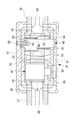
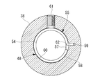
- FIG. 1 It is a whole lineblock diagram showing a medical manipulator system provided with an operation input device concerning one embodiment of the present invention. It is a figure which shows the manipulator, operation input device, and control part which are used for the medical manipulator system of FIG. It is a perspective view which shows the operation input apparatus with which the medical manipulator system of FIG. 1 is equipped. It is a top view which shows the internal structure of the joint of the operation input apparatus of FIG. It is a longitudinal cross-sectional view which shows the internal structure of the joint of the operation input apparatus of FIG. It is the perspective view which shows the (a) exploded perspective view and (b) insertion to the insertion hole of the shaft unit with which the joint of the operation input device of FIG. 3 is equipped. It is a top view of the shaft unit of FIG.
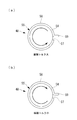
- FIG. 6 (a) It is a figure which shows the rotation direction of the shaft member which generate
- FIG. 4 is a partial cross-sectional view of a link member showing a push screw for adjusting a friction torque, which is a first modification of the operation input device of FIG. 3.
- FIG. 5 is a partial perspective view of a shaft unit showing a shaft member having a slit for adjusting a friction torque and a taper female screw, which is a second modification of the operation input device of FIG. 3. It is a figure which shows the modification of the medical manipulator system of FIG.
- a medical manipulator system 1 includes an operation input device 2 operated by an operator O, a manipulator 3 inserted into a body cavity of a patient P, and an operation input device 2.
- the control part 4 which controls the manipulator 3 based on operation of these, and the monitor 5 are provided.
- the manipulator 3 is inserted into the body of the patient P via an insertion portion 6 inserted into the body cavity of the patient P and a channel R formed through the insertion portion 6 in the longitudinal direction. And a distal end side operation unit 7 to be inserted.
- Each distal end side operation unit 7 is provided at the distal end of the movable portion 9, a long portion 8 that is disposed in the channel R so as to be movable in the longitudinal direction, a movable portion 9 provided at the distal end of the long portion 8, and the movable portion 9.
- the high-frequency gripper 11 is provided, and a distal-end drive unit 10 that is disposed on the proximal end side of the long portion 8 and drives the movable portion 9 by a power transmission member such as a wire (not shown).
- the tip drive unit 10 includes an electrical drive source (not shown) such as a motor that applies tension to the wire in accordance with an operation command from the control unit 4.
- Each movable part 9 has three joints for swinging the treatment part 11 such as a grasping forceps disposed at the distal end about an axis perpendicular to the longitudinal axis of the long part 8 as indicated by white arrows in FIG. 12, 13, 14 and one joint 15 that rotates around the longitudinal axis of the long portion 8.
- Each movable part 9 can position the tip position of each grasping forceps 11 three-dimensionally by the operation of these four joints 12, 13, 14, 15.
- manipulator 3 is connected to the proximal end side of each distal end side operation unit 7, and advances and retracts each distal end side operation unit 7 in the longitudinal direction of the insertion unit 6, and in the vicinity of the distal end of the insertion unit 6, the long portion 8.
- the manipulator 3 is connected to the proximal end side of each distal end side operation unit 7, and advances and retracts each distal end side operation unit 7 in the longitudinal direction of the insertion unit 6, and in the vicinity of the distal end of the insertion unit 6, the long portion 8.
- the operation input device 2 is operated by the first operation unit 19 operated by the hand of the operator O and the wrist or arm of the operator O.
- a second operation unit 20 and a command transmission unit 21 that transmits an operation command input by these operation units 19 and 20 to the manipulator 3 are provided.
- the first operation unit 19 is configured to be similar to the movable unit 9 of the manipulator 3, and the gripping unit 25 that is gripped by the hand of the operator O and the same number of joints J 1, J 2, J 3 as the movable unit 9. , K, an arm portion 22 that supports the grip portion 25, and a main body portion 23 that supports the arm portion 22.
- the grip portion 25 is formed in a rod shape that is gripped by the operator O, and includes a slide sensor 32 and three push buttons 33, 34, and 35 on the outer peripheral surface thereof.
- the slide sensor 32 is provided so as to be slidable in the longitudinal axis direction of the rod-shaped grip portion 25 and is used to adjust the opening / closing angle of the gripper, which is one of the main functions of the high-frequency gripper 11 as an end effector. It is like that.
- the slide sensor 32 includes a slidable slider 36. The slider 36 is arranged at a position where the operator O can easily operate with the index finger of the hand holding the grip portion 25, and is kept stopped at that position when the index finger is released.
- buttons 33, 34, 35 two push buttons 33, 34 are arranged side by side in the slide direction of the slider 36 of the slide sensor 32. These push buttons 33 and 34 are on / off switches for performing high-frequency energization from the gripper, which is another main function of the high-frequency gripper 11 as an end effector.
- the two push buttons 33 and 34 are used by being selectively pushed, for example, in the treatment in the incision mode and the coagulation mode.
- the other one push button 35 is arranged at a position different from the slide sensor 32 or the like by 90 ° in the circumferential direction of the grip portion 25.
- the push button 35 is, for example, a clutch button, and can be switched between connection and disconnection between the operation input device 2 and the manipulator 3 each time the button is pressed.
- the arm portion 22 includes four link members 37, 38, 39, and 40, three joints J1, J2, and J3 that connect the four link members 37, 38, 39, and 40 in series, and the entire body portion. And a single rotary joint K that is rotatably supported around the horizontal axis.
- the grip portion 25 is fixed to the tip of the most advanced link member 37.
- the joint J1 will be described as an example.
- the joint J ⁇ b> 1 includes spur gears (gears) 41 and 42 that are fixed to two adjacent link members 37 and 38 and mesh with each other, and the two spur gears 41 and 42.
- a connecting member 51 is provided that is attached to the two link members 37 and 38 and connects the two link members 37 and 38 so as to be swingable around each parallel axis.
- the two spur gears 41 and 42 fixed to the two link members 37 and 38 are always kept in mesh with each other by the connecting member 51. Therefore, if the relative angle of the two link members 37 and 38 connected by the joint J1 is changed, the swing angle of the connecting member 51 with respect to one link member 37 and the swing of the other link member 38 with respect to the connecting member 51 are increased. The angle is operated so as to be a half of the relative angle of the two link members 37 and 38. Thus, a so-called double joint structure joint is formed in which the two link members 37 and 38 are swung around the two axes.
- the spur gear 41 fixed to the first link member 37 is used.
- An angle sensor (sensor) 47 is disposed at the axial position, and a shaft unit (friction generating portion) 48 is disposed at the axial position of the spur gear 42 fixed to the second link member 38.
- the angle sensor 47 is an encoder, and includes a sensor main body 49 fixed to the first link member 37 and a detection shaft 50 fixed to the connecting member 51, and the first link member 37 and the connecting member 51 are connected to each other. The relative angle between them is detected. As described above, since the relative angular displacement between the link member 37 and the connecting member 51 is exactly half of the relative angular displacement between the first link member 37 and the second link member 38, the angle sensor 47 has two links. The relative angular displacement of the members 37 and 38 is indirectly detected as a half angle signal.
- the shaft unit 48 is wound around the outer peripheral surface of the shaft member 54 fixed to the connecting member 51 and tightens the shaft member 54 radially inward.
- a pair of leaf spring members (elastic members) 55 is provided.
- the shaft member 54 is fixed to the connecting member 51 by screws 56.
- the plate spring member 55 includes a cylindrical fastening portion 58 having a slit 57, and a protruding portion 59 that is bent and protruded radially outward at one end in the circumferential direction of the fastening portion 58.
- the inner diameter dimension of the fastening portion 58 in the free state is set smaller than the outer diameter dimension of the shaft member 54.
- the pair of leaf spring members 55 provided in the shaft unit 48 are attached to the shaft member 54 with different winding directions of the fastening portions 58 with respect to the protruding portions 59.
- the fastening portion 58 is wound counterclockwise around the outer peripheral surface of the shaft member 54 will be described as an example.
- FIG. 7A the leaf spring member 55 is fixed and the shaft is fixed. When a torque that rotates the member 54 counterclockwise is applied, the fastening portion 58 is pulled in the direction of narrowing the slit 57 due to friction between the outer peripheral surface of the shaft member 54 and the inner surface of the fastening portion 58. Torque increases.
- the joint unit J1 will be described as an example.
- the shaft unit 48 is inserted into the insertion hole 60 penetrating the second link member 38, and the first and second The link members 37 and 38 are fixed to at least one of two connecting members 51 detachably attached so as to be sandwiched from both sides in the axial direction of the spur gears 41 and 42 by screws 56.
- the insertion hole 60 provided in the second link member 38 is provided with grooves 62 formed along the longitudinal direction at two locations spaced in the circumferential direction. ing.
- the groove 62 has a groove width dimension substantially equal to the thickness of the leaf spring member 55 and accommodates the two protrusions 59 of the pair of leaf spring members 55 when the shaft unit 48 is inserted into the insertion hole 60. It is supposed to be. That is, the shaft member 54 and the pair of leaf spring members 55 can be inserted into the insertion hole 60 and taken out from the insertion hole 60 in the form of the shaft unit 48. Then, by accommodating the protruding portion 59 in the groove 62, the leaf spring member 55 is locked to the second link member 38 so as not to move in the circumferential direction of the fastening portion 58.
- each of the joints J1, J2, and J3 constituting the arm portion 22 includes, as shown in FIG. 8, link members 37, 38, and 39, which are disposed on the distal end side from the joints J1, J2, and J3. It can be considered that the torque due to the sum of the weights of J1, J2, J3 and the gripping portion 25 being applied to the combined center of gravity position acts. Therefore, the friction torque generated in each joint J1, J2, J3 is set to exceed the torque acting on the joints J1, J2, J3 due to their own weight.
- each joint J1, J2, J3 The torque due to its own weight acting on each joint J1, J2, J3 is the largest because the combined center of gravity from the joints J1, J2, J3 is farthest, that is, all the joints J1, J2, J3 are extended. State. As shown in FIG. 8A, since the total weight m J3 of the members 37, 38, and 39 on the distal end side is applied to the combined center of gravity position x J3 , the joint J3 on the most proximal side is placed on the joint J3.
- the two joints J1 and J2 on the distal end side also have members 37 and 38 on the distal end side than the joints J1 and J2, as shown in FIG. 8 (b).
- the pair of leaf spring members 55 generates a friction torque larger than the torques T J1 , T J2 , and T J3 so that they can counter any direction of the torque applied to the shaft member 54.
- the spring constant and dimensions of the fastening portion 58 are set. That is, the spring constant of the leaf spring member 55 is set to be larger for the joint J3 on the proximal end side.
- the connecting member 51 includes a concave portion 53 that fits to a boss portion 52 provided in each of the link members 37 and 38.
- the connecting member 51 is fitted in a snap-fit manner to the two link members 37 and 38.
- the two link members 37 and 38 are connected to each other so as to be swingable.
- the connecting member 51 is provided with a circumferential groove (wiring groove) 65 in the vicinity of the peripheral edge thereof over the entire circumference.
- the joint J1 will be described as an example. As shown in FIGS. 4 and 5, the cable 66 guided through the cavity of one link member 37 is connected to the connecting member 51 from the opening of the link member 37.
- the cable 66 can be easily wired in a route that avoids interference with the spur gears 41 and 42.
- the rotary joint K arranged on the most proximal side of the arm part 22 includes a rotary part (not shown) that is rotatably supported with respect to the main body part 23, and the relative angle of the rotary part with respect to the main body part 23.
- An angle sensor such as an encoder for detecting displacement, a shaft member (not shown) fixed to the rotating part, and a pair of leaf spring members fixed to the main body part 23 and wound around the outer peripheral surface of the shaft member (Not shown).
- the friction torque at the rotary joint K is set by increasing the torque due to the weight of the rotary joint K when the arm portion 22 is extended in the horizontal direction with the joints J1 and J2 extended and the joint J3 bent at 90 °. It has been done to exceed the size.
- the second operation unit 20 includes an arm rest 26 fixed to the main body 23 of the first operation section 19 and a direct support for movably supporting the arm rest 26 and the first operation section 19. And a moving mechanism 27.
- the arm rest 26 is disposed at a position where the arm near the wrist of the hand that grips the grip portion 25 is placed when the operator O grips the grip portion 25 of the first operation portion 19.
- the linear motion mechanism 27 can move the slider 28 in two horizontal directions perpendicular to each other, as indicated by a solid arrow in FIG. 2 and a slider 28 that fixes the arm rest 26 and the first operation unit 19. And a linear guide 29 to be supported.
- the position of the first operation unit 19 can be moved while maintaining the posture in which the first operation unit 19 is held by moving the slider 28 in the horizontal direction by the arm placed on the arm rest 26. It has become.
- the second operation unit 20 can input an operation command with the wrist or arm of the operator O, and can generate the force input with the wrist or arm as the mechanical driving force of the two sliders 28. It is like that.
- the command transmission unit 21 includes an electrical signal transmission unit 30 that connects the first operation unit 19 and the distal end drive unit 10, and a mechanical power transmission unit that connects the second operation unit 20 and the proximal end side operation unit 16. 31.
- the electric signal transmission unit 30 transmits an operation command including the electric signal generated by the first operation unit 19 to the control unit 4 and supplies the command signal generated by the control unit 4 to each motor of the tip driving unit 10. It is supposed to be.
- the control unit 4 calculates the rotational movement amount and the rotational speed of each motor of the tip driving unit 10 based on the operation command generated by the first operation unit 19, and controls each motor.
- control unit 4 controls the end effector so as to change the opening / closing angle of the high-frequency gripper 11 in accordance with the slide position of the slider 36 of the slide sensor 32 provided in the grip unit 25 of the first operation unit 19. It is like that.
- the control unit 4 functions to be assigned to the push buttons 33, 34, and 35, that is, turning on and off the energization in the incision mode and energizing in the coagulation mode. This controls the on / off of the clutch and the engagement / disengagement of the clutch.
- the operation input device 2 and the medical manipulator system 1 according to the present embodiment configured as described above will be described below.
- the insertion part 6 of the manipulator 3 is inserted into the body cavity of the patient P, and the channel R of the insertion part 6 is inserted.
- the movable part 9 and the long part 8 are inserted into the body of the patient P.
- the operator O operates the operation input device 2 while confirming an image acquired by an endoscope (not shown) on the monitor 5 in a state where the movable portion 9 is arranged close to the affected part in the body cavity. .
- the operator O holds the grip portion 25 of the first operation portion 19 with one hand, and the arm of the hand is placed on the arm rest 26 of the second operation portion 20. Put it on.
- the slider 28 to which the arm rest 26 is fixed moves in the direction of the force, and the amount of movement is the amount of straight movement in the forward / backward direction.
- the front end position of the high-frequency gripper 11 positioned at the front end of the movable portion 9 can be manually moved roughly in the forward / backward direction and the left / right direction.
- the amount of movement is detected by the angle sensors 47 provided at the joints J1, J2, J3, and K.
- the electric signal is transmitted to the control unit 4.
- an electrical operation command for operating the joints 12, 13, 14, 15 of the movable unit 9 so as to coincide with the angles of the joints J 1, J 2, J 3, K detected by the angle sensor 47. Is calculated and supplied to the motors connected to the joints 12, 13, 14, and 15.
- the tip position of the high-frequency gripper 11 provided at the tip of the movable portion 9 is precisely and electrically moved as instructed by the hand movement.
- the control unit 4 opens and closes the high frequency gripper 11 according to the position of the slider 36.
- the slider 36 is easily slid in the longitudinal direction of the grip part 25 by the operation of the index finger. Can be made.
- the operator O slides the thumb and presses the push button 35. Since the push button 35 as the clutch button is arranged at a position shifted from the position of the thumb holding the grip portion 25, it is possible to prevent erroneous operation of the clutch button and to interrupt the operation of the clutch. Can be meant.
- each joint J1, J2, J3, and K the total weight of the members arranged on the tip side of the joints J1, J2, J3, and K rotates the joints J1, J2, J3, and K. It acts as its own weight torque.
- each joint J1, J2, J3, K is It remains stationary.
- the joints J1, J2, J3, and K of the arm portion 22 are stationary even when the operator O releases the gripping portion 25 in a state where the operation input device 2 and the manipulator 3 are disconnected.
- the grip portion 25 and the arm portion 22 are stationary on the spot and maintained in the same posture, the next time the operation input device 2 and the manipulator 3 are restarted, the operation input device 2 and the manipulator 3 There is an advantage that it can be easily restarted by preventing the occurrence of displacement.
- the shaft member 54 fixed to the connecting member 51 and the leaf spring member 55 fixed to the link members 38, 39, and 40 and wound around the outer peripheral surface of the shaft member 54 can reduce the self-weight torque. Since the opposing friction torque is generated, the arm portion 22 in the interlocking cut state can be stably maintained in a stationary state with a simple configuration. In particular, since a large-scale device such as a motor is not used, the arm portion 22 can be downsized.
- the joints J1, J2, J3, and K are generated not only to generate a large frictional torque but also to generate a frictional torque that can counter the maximum value of the self-weight torque acting on each joint J1, J2, J3, and K. Since the friction torque is adjusted every time, when the operator O operates the grip part 25, it can be easily operated by the force applied to the grip part 25. In particular, when the grip portion 25 is moved by an external force that generates a torque exceeding its own weight torque, not only one of the joints J1, J2, J3, K is moved, but all the joints J1, J2, J3, K are moved. By adjusting the friction torque so as to move, it is possible to prevent the operability from deteriorating.
- the shaft unit 48 is inserted into the insertion hole 60 provided in the link members 38, 39, 40 along the longitudinal direction, and the friction torque is generated simply by fixing the shaft member 54 and the connecting member 51 with the screw 56.
- Mechanism can be configured.
- the shaft unit 48 can be removed from the insertion hole 60. That is, by assembling and disassembling the joints J1, J2, and J3 that generate the friction torque by inserting and removing the shaft unit 48 in which the shaft member 54 and the leaf spring member 55 are assembled to and from the insertion hole 60.
- the leaf spring member 55 can be easily replaced.
- the joints having a double joint structure are exemplified as the three joints J1, J2, and J3 of the arm unit 22.
- a joint having a single axis is used. It may be adopted.
- the joint J1 will be described as an example. In this case, if the shaft member 54 is fixed to one link member 37 and the leaf spring member 55 wound around the shaft member 54 is fixed to the other link member 38. Good.
- the leaf spring member 55 is exemplified as an elastic member for tightening the outer peripheral surface of the shaft member 54, but instead of this, a coil spring formed in a cylindrical shape as a whole by spirally winding a spring material. A member may be adopted.
- a mechanism for adjusting the tightening force by the leaf spring member 55 from the outside such as a push screw (adjustment unit) 61 shown in FIG.
- a push screw (adjustment unit) 61 shown in FIG.
- the size of the friction torque can be adjusted by the push screw 61.
- a plurality of slits are formed in the shaft member 54 at intervals in the circumferential direction, and a taper female screw (adjustment part) 67 is provided at the center, whereby the taper female screw 67 is provided.
- the amount of friction torque generated by the leaf spring member 55 may be adjusted from the outside by changing the outer diameter of the shaft member 54 by adjusting the fastening amount of a taper male screw (not shown) to be fastened.
- the friction torque is adjusted based on the torques related to the joints J1, J2, J3, and K in a state where the joints J1, J2, and J3 of the arm portion 22 are all extended.
- the center position (sweet spot) of the movement range of each joint J1, J2, J3, K is defined, and the friction torque generated at the joints J1, J2, J3, K when the force is applied thereto is
- the friction torque may be adjusted so that the joints J1, J2, J3, and K coincide.
- the joints J1, J2, J3, and K can be operated in conjunction with each other while compensating for the own weight torque, and high operability can be achieved.
- a contact sensor (contact detection unit) 63 that detects whether or not the hand of the operator O is in contact with the grip portion 25 is provided. It is determined whether or not the relative angular displacement detected by the angle sensor 47 and sent to the control unit 4 is equal to or greater than a predetermined threshold in a state in which no contact is detected.
- An informing unit 64 may be provided. The contact sensor 63 detects, for example, whether or not the thumb has touched at a position where the thumb of the hand held by the operator O is placed when the grip 25 is gripped.
- the joint J1 will be described as an example.
- the angle sensor 47 causes the link member to move.
- the relative angular displacement between 37 and 38 is detected, and when the movement is large, the notification unit 64 notifies. Based on this, if the leaf spring member 55 is replaced or the tightening force by the leaf spring member 55 is adjusted, the positional deviation when the operation input device 2 and the manipulator 3 are disconnected is prevented, and the operation is performed. Can be easily.
- the angle sensor 47 is disposed at each joint and the relative angular displacement between the link members 37, 38, 39, and 40 is detected.
- the present invention is not limited to this.
- the relative angular displacement between the link members 37, 38, 39, and 40 may be detected by any method.
Landscapes
- Health & Medical Sciences (AREA)
- Engineering & Computer Science (AREA)
- Life Sciences & Earth Sciences (AREA)
- Surgery (AREA)
- Robotics (AREA)
- Medical Informatics (AREA)
- Biomedical Technology (AREA)
- Heart & Thoracic Surgery (AREA)
- Nuclear Medicine, Radiotherapy & Molecular Imaging (AREA)
- Molecular Biology (AREA)
- Animal Behavior & Ethology (AREA)
- General Health & Medical Sciences (AREA)
- Public Health (AREA)
- Veterinary Medicine (AREA)
- Ophthalmology & Optometry (AREA)
- Manipulator (AREA)
Abstract
この操作入力装置は、患部の観察または処置を行うマニピュレータ(3)への操作指令を入力する操作入力装置(2)であって、操作者(O)の手により把持される把持部(25)と、該把持部(25)を移動可能に支持するアーム部(22)とを備え、該アーム部(22)が、2以上のリンク部材と、隣接する一対のリンク部材をその長手軸に交差する関節軸回りに揺動可能に連結する1以上の関節(J1,J2,J3)とを備え、各該関節(J1,J2,J3)が、連結する各リンク部材の相対角度変位を検出するセンサと、トルクのかかる方向とは逆方向に摩擦トルクを発生させる摩擦発生部とを備える操作入力装置(2)を提供する。
Description
本発明は、操作入力装置および医療用マニピュレータシステムに関するものである。
従来、操作者によって操作されることにより動作指令を入力する多関節の操作部と、該操作部の操作により入力された動作指令によって動作する多関節のマニピュレータとを備える手術用マニピュレータシステムが知られている(例えば、特許文献1参照。)。
この特許文献1においては、操作部とマニピュレータとの接続および切断が可能であるとともに、操作部の各関節にモータが備えられている。そして、操作部とマニピュレータとが切断されている状態では、モータを使って操作部の各関節をロックすることにより、切断時における操作部とマニピュレータとの位置ズレを防止している。
この特許文献1においては、操作部とマニピュレータとの接続および切断が可能であるとともに、操作部の各関節にモータが備えられている。そして、操作部とマニピュレータとが切断されている状態では、モータを使って操作部の各関節をロックすることにより、切断時における操作部とマニピュレータとの位置ズレを防止している。
しかしながら、特許文献1の手術用マニピュレータシステムのように、操作部にモータを備える場合には、操作部の構造が繁雑になるとともに大型化し、かつ、コストが高くつく。
本発明は、上述した事情に鑑みてなされたものであって、操作部の各関節にモータを設けることなく、切断時における操作部とマニピュレータとの位置ズレを防止することができる操作入力装置および医療用マニピュレータシステムを提供することを目的としている。
上記目的を達成するために本発明は以下の手段を提供する。
本発明の一態様は、患部の観察または処置を行うマニピュレータへの操作指令を入力する操作入力装置であって、操作者の手により把持される把持部と、該把持部を移動可能に支持するアーム部とを備え、該アーム部が、2以上のリンク部材と、隣接する一対の前記リンク部材をその長手軸に交差する関節軸回りに揺動可能に連結する1以上の関節とを備え、各該関節が、トルクのかかる方向とは逆方向に摩擦トルクを発生させる摩擦発生部を備える操作入力装置を提供する。
本発明の一態様は、患部の観察または処置を行うマニピュレータへの操作指令を入力する操作入力装置であって、操作者の手により把持される把持部と、該把持部を移動可能に支持するアーム部とを備え、該アーム部が、2以上のリンク部材と、隣接する一対の前記リンク部材をその長手軸に交差する関節軸回りに揺動可能に連結する1以上の関節とを備え、各該関節が、トルクのかかる方向とは逆方向に摩擦トルクを発生させる摩擦発生部を備える操作入力装置を提供する。
本態様によれば、操作者が把持部を把持して移動させると、操作者が把持部に加えた外力が、アーム部の関節にトルクとして作用し、関節の動作によって2以上のリンク部材の相対角度を変化させる。これにより、操作者により把持部への操作指令が入力され、該操作指令に基づいてマニピュレータを作動させることができる。
この場合において、関節にトルクが作用すると、摩擦発生部によりトルクがかかる方向とは逆方向に摩擦トルクが発生する。すなわち、操作者が把持部から手を放すことにより、把持部およびアーム部の自重によって各関節にトルクがかかるが、摩擦発生部によって発生する摩擦トルクを自重によるトルクの最大値より大きく設定しておくことにより、操作者が把持部を支持していなくても、アーム部の各関節が静止した状態に維持される。
したがって、操作入力装置とマニピュレータとの連動が切断された状態で、操作者が把持部から手を放しても、把持部およびアーム部がその場で静止し同じ姿勢に維持されるので、次に操作入力装置とマニピュレータとの連動を再開させるときに、操作入力装置とマニピュレータとの位置ズレの発生を防止して、容易に再開させることができる。
上記態様においては、前記摩擦発生部が、前記一対のリンク部材の一方に固定され前記関節軸に沿って延びるシャフト部材と、前記一対のリンク部材の他方に固定され、前記シャフト部材の外周面に巻き付けられて、径方向内方に締め付ける弾性部材とを備えていてもよい。
このようにすることで、関節により連結された2つのリンク部材の相対角度を変化させる方向に外力が作用すると、一方のリンク部材に固定されたシャフト部材と他方のリンク部材に固定された弾性部材との間に、両者をシャフト部材の周方向に相対移動させるトルクが作用する。
このようにすることで、関節により連結された2つのリンク部材の相対角度を変化させる方向に外力が作用すると、一方のリンク部材に固定されたシャフト部材と他方のリンク部材に固定された弾性部材との間に、両者をシャフト部材の周方向に相対移動させるトルクが作用する。
弾性部材は、シャフト部材の外周面に巻き付けられてシャフト部材を径方向内方に締め付けているので、両者間の静止摩擦力によって、外力によるトルクに対抗する摩擦トルクが発生する。弾性部材による締め付け力を適当に調節しておくことにより、重力によるトルクより大きく、重力を超える外力によるトルクより小さい摩擦トルクを発生させることができる。その結果、操作者が把持部から手を放したときに静止状態に維持され、操作者により把持部に加えられる比較的小さい外力によって容易に各リンク部材の姿勢を変化させることができる。
また、上記態様においては、前記他方のリンク部材に、前記シャフト部材の外周面に前記弾性部材を巻き付けたシャフトユニットをその長手軸方向に挿入させる挿入孔が設けられ、前記弾性部材が、前記シャフト部材の外周面に巻き付けられる略円筒状の締結部と、該締結部から径方向外方に延びる突出部とを備え、前記挿入孔に、前記シャフトユニットを挿入するときに前記突出部が長手軸方向に挿入されて周方向に係止する溝が設けられていてもよい。
このようにすることで、シャフト部材の外周面に弾性部材の略円筒状の締結部を巻き付けると、弾性部材の突出部がシャフト部材の径方向外方に延びたシャフトユニットが構成される。このようにして構成されたシャフトユニットを他方のリンク部材に設けられた挿入孔に長手方向に挿入していくと、挿入孔に設けられた溝に弾性部材の突出部が挿入され、弾性部材が、他方のリンク部材の挿入孔内に周方向に移動しないように固定される。
シャフト部材は一方のリンク部材に固定されているので、2つのリンク部材の間に相対角度変位を生じる方向に外力によるトルクが加わると、シャフト部材と弾性部材の締結部との間の摩擦によって摩擦トルクが発生する。すなわち、このように構成することで、シャフト部材と弾性部材とを組み付けたシャフトユニットを挿入孔に対して挿脱することにより、摩擦トルクを発生する関節の組立・分解を容易に行うことができるとともに、摩擦部材を容易に交換することができる。
また、上記態様においては、前記関節が、隣接する2つの前記リンク部材にそれぞれ固定され相互に噛み合う2つの歯車と、これら2つの歯車の平行な2つの軸線の各々を中心として搖動可能となるように2つの前記リンク部材にそれぞれ取り付けられて、2つの前記リンク部材を連結する連結部材とを備え、前記摩擦発生部が、前記一対のリンク部材の一方に固定された前記歯車の軸線に沿って延び、前記連結部材および前記一方のリンク部材の一方に固定されたシャフト部材と、前記連結部材および前記一方のリンク部材の他方に固定され、前記シャフト部材の外周面に巻き付けられて、前記シャフト部材を径方向内方に締め付ける弾性部材とを備えていてもよい。
このようにすることで、2つのリンク部材にそれぞれ固定された2つの歯車は、連結部材によって常に噛み合った状態に維持されているので、関節により連結された2つのリンク部材の相対角度を変化させると、一方のリンク部材に対する連結部材の揺動角度と、該連結部材に対する他方のリンク部材の揺動角度とが、2つのリンク部材の相対角度の半分となる。これにより2つの軸線回りに2つのリンク部材を揺動させる、いわゆるダブルジョイント構造の関節が構成される。
この場合に、関節により連結された2つのリンク部材の相対角度を変化させる方向に外力が作用すると、一方の歯車の軸線に沿って延び、連結部材および一方のリンク部材のうち一方に固定されたシャフト部材と、連結部材および一方のリンク部材のうち他方に固定され、シャフト部材の外周面に巻き付けられた弾性部材との間に、両者をシャフト部材の周方向に相対移動させるトルクが作用する。
弾性部材は、シャフト部材の外周面に巻き付けられてシャフト部材を径方向内方に締め付けているので、両者間の静止摩擦力によって、外力によるトルクに対抗する摩擦トルクが発生する。弾性部材による締め付け力を適当に調節しておくことにより、重力によるトルクより大きく、重力を超える外力によるトルクより小さい摩擦トルクを発生させることができる。その結果、ダブルジョイント構造の関節を用いた場合においても、操作者が把持部から手を放したときに静止状態に維持され、操作者により把持部に加えられる比較的小さい外力によって容易に各リンク部材の姿勢を変化させることができる。
また、上記態様においては、前記一方のリンク部材に、前記シャフト部材の外周面に前記弾性部材を巻き付けたシャフトユニットをその長手軸方向に挿入させる挿入孔が設けられ、前記弾性部材が、前記シャフト部材の外周面に巻き付けられる略円筒状の締結部と、該締結部から径方向外方に延びる突出部とを備え、前記挿入孔に、前記シャフトユニットを挿入するときに前記突出部が前記長手軸方向に挿入されて周方向に係止する溝が設けられていてもよい。
このようにすることで、ダブルジョイント構造の関節においてもシャフト部材と弾性部材とを組み付けたシャフトユニットを挿入孔に対して挿脱することにより、摩擦トルクを発生する関節の組立・分解を容易に行うことができるとともに、摩擦部材を容易に交換することができる。
また、上記態様においては、前記連結部材に、前記関節を超えて2つの前記リンク部材間で電気信号を伝達するケーブルを、前記歯車から離れたルートに沿って配線する配線用溝を備えていてもよい。
このようにすることで、ダブルジョイント構造の関節に存在する歯車から離れたルートに沿って、電気信号を伝達するケーブルを配線でき、両者の干渉をなくして、健全な状態に維持することができる。
このようにすることで、ダブルジョイント構造の関節に存在する歯車から離れたルートに沿って、電気信号を伝達するケーブルを配線でき、両者の干渉をなくして、健全な状態に維持することができる。
また、上記態様においては、前記弾性部材が、前記シャフト部材に加わるトルクの方向に応じて締め付け力を増減させる一対の前記締結部を備え、前記一対の締結部はその締め付け力が増す方向が互いに逆方向となるように配置されていてもよい。
このようにすることで、一方の締結部により一方向のトルクに対抗する摩擦トルクを発生させ、他方の締結部により他方向のトルクに対抗する摩擦トルクを発生させることができる。これにより、関節に対していずれの方向の自重によるトルクが加わっても、いずれかの締結部により発生される摩擦トルクによって、関節を静止した状態に維持することができる。すなわち、操作者が把持部から手を放すときの把持部およびアーム部の姿勢にかかわらず、把持部およびアーム部を静止した状態に維持することができる。
このようにすることで、一方の締結部により一方向のトルクに対抗する摩擦トルクを発生させ、他方の締結部により他方向のトルクに対抗する摩擦トルクを発生させることができる。これにより、関節に対していずれの方向の自重によるトルクが加わっても、いずれかの締結部により発生される摩擦トルクによって、関節を静止した状態に維持することができる。すなわち、操作者が把持部から手を放すときの把持部およびアーム部の姿勢にかかわらず、把持部およびアーム部を静止した状態に維持することができる。
また、上記態様においては、前記弾性部材による締め付け力を調節する調節部を備えていてもよい。
このようにすることで、経時変化等により弾性部材による締め付け力が低下しても、調節部により締め付け力を調節して適正な摩擦トルクを発生させることができる。また、関節が複数存在する場合には、操作者が把持部を把持して移動させる際に、いずれかの関節のみが動作するのではなく、全ての関節がバランスよく動作することでスムーズな操作指令を入力することができる。したがって、調節部により締め付け力を調節することで、関節をバランスよく動作させることができる。
このようにすることで、経時変化等により弾性部材による締め付け力が低下しても、調節部により締め付け力を調節して適正な摩擦トルクを発生させることができる。また、関節が複数存在する場合には、操作者が把持部を把持して移動させる際に、いずれかの関節のみが動作するのではなく、全ての関節がバランスよく動作することでスムーズな操作指令を入力することができる。したがって、調節部により締め付け力を調節することで、関節をバランスよく動作させることができる。
また、上記態様においては、前記アーム部が、3以上の前記リンク部材と、2以上の前記関節とを備え、前記弾性部材のバネ定数が、基端側の前記関節ほど大きく設定されていてもよい。
複数の関節には、該関節よりも先端側に配置されている部材の自重によるトルクがかかるので、基端側の関節ほど大きなトルクがかかる。このようにすることで、基端側の関節ほど大きな摩擦トルクを発生させることができ、把持部から手を放したときに静止状態に維持することができるとともに、先端側の関節においては発生させる摩擦トルクを軽減して、スムーズな操作が可能となる。
複数の関節には、該関節よりも先端側に配置されている部材の自重によるトルクがかかるので、基端側の関節ほど大きなトルクがかかる。このようにすることで、基端側の関節ほど大きな摩擦トルクを発生させることができ、把持部から手を放したときに静止状態に維持することができるとともに、先端側の関節においては発生させる摩擦トルクを軽減して、スムーズな操作が可能となる。
また、上記態様においては、前記把持部が、操作者の手に接触しているか否かを検知する接触検知部を備え、各前記リンク部材の相対角度変位を検出するセンサと、該接触検知部により、操作者の手の接触が検知されていない状態で、前記センサにより検出される相対角度変位が所定の閾値以上に変化したときに、その旨を報知する報知部とを備えていてもよい。
このようにすることで、経時変化等により弾性部材が発生する摩擦トルクが低減した場合等に、自重によるトルクを支えきれずに関節が動いてしまうと、センサによりリンク部材間の相対角度変位が検出され、所定の閾値以上相対角度変位が生じた場合に報知部により報知される。これに基づいて、弾性部材を交換し、あるいは、弾性部材による締め付け力を調節すれば、操作入力装置とマニピュレータとの連動を切断した際の位置ズレを防止し、操作を容易にすることができる。
このようにすることで、経時変化等により弾性部材が発生する摩擦トルクが低減した場合等に、自重によるトルクを支えきれずに関節が動いてしまうと、センサによりリンク部材間の相対角度変位が検出され、所定の閾値以上相対角度変位が生じた場合に報知部により報知される。これに基づいて、弾性部材を交換し、あるいは、弾性部材による締め付け力を調節すれば、操作入力装置とマニピュレータとの連動を切断した際の位置ズレを防止し、操作を容易にすることができる。
また、上記態様においては、他の前記リンク部材と前記連結部材との相対角度変位を検出するセンサを備えていてもよい。
このようにすることで、一のリンク部材と連結部材との間に摩擦トルクを発生する機構が構成され、他のリンク部材と連結部材との間に、リンク部材間の相対角度変位を検出するセンサが配置されるので、スペースを有効利用することができ、ダブルジョイント構造の関節を小型化できる。上述したように、リンク部材と連結部材との相対角度変位は、リンク部材間の相対角度変位の半分となるので、センサは、リンク部材間の相対角度変位をその半分の値として間接的に検出することができる。
このようにすることで、一のリンク部材と連結部材との間に摩擦トルクを発生する機構が構成され、他のリンク部材と連結部材との間に、リンク部材間の相対角度変位を検出するセンサが配置されるので、スペースを有効利用することができ、ダブルジョイント構造の関節を小型化できる。上述したように、リンク部材と連結部材との相対角度変位は、リンク部材間の相対角度変位の半分となるので、センサは、リンク部材間の相対角度変位をその半分の値として間接的に検出することができる。
また、本発明の他の態様は、患部の観察または処置を行うマニピュレータと、上記いずれかの操作入力装置と、該操作入力装置により入力された操作指令に基づいて前記マニピュレータを制御する制御部とを備える医療用マニピュレータシステムを提供する。
上記態様においては、前記マニピュレータが、前記操作入力装置と相似する関節構成となるように一以上の関節を備えていてもよい。
上記態様においては、前記マニピュレータが、前記操作入力装置と相似する関節構成となるように一以上の関節を備えていてもよい。
本発明によれば、操作部の各関節にモータを設けることなく、切断時における操作部とマニピュレータとの位置ズレを防止することができるという効果を奏する。
本発明の一実施形態に係る操作入力装置2および医療用マニピュレータシステム1について、図面を参照して以下に説明する。
本実施形態に係る医療用マニピュレータシステム1は、図1に示されるように、操作者Oにより操作される操作入力装置2と、患者Pの体腔内に挿入されるマニピュレータ3と、操作入力装置2の操作に基づいてマニピュレータ3を制御する制御部4と、モニタ5とを備えている。
本実施形態に係る医療用マニピュレータシステム1は、図1に示されるように、操作者Oにより操作される操作入力装置2と、患者Pの体腔内に挿入されるマニピュレータ3と、操作入力装置2の操作に基づいてマニピュレータ3を制御する制御部4と、モニタ5とを備えている。
マニピュレータ3は、例えば、図2に示されるように、患者Pの体腔内に挿入される挿入部6と、該挿入部6の長手方向に貫通形成されたチャネルRを介して患者Pの体内に挿入される先端側動作部7とを備えている。各先端側動作部7は、チャネルR内に長手方向に移動可能に配置される長尺部8と、該長尺部8の先端に備えられた可動部9と、可動部9の先端に設けられた高周波グリッパ11と、長尺部8の基端側に配置され、図示しないワイヤ等の動力伝達部材によって可動部9を駆動する先端駆動部10とを備えている。先端駆動部10は、制御部4からの動作指令に応じてワイヤに張力を付与するモータ等の電気的な駆動源(図示略)を備えている。
各可動部9は、図2に白抜きの矢印で示すように、先端に配置される把持鉗子等の処置部11を長尺部8の長手軸に直交する軸線回りに揺動させる3つの関節12,13,14と、長尺部8の長手軸回りに回転させる1つの関節15とを有している。各可動部9は、これら4つの関節12,13,14,15の動作によって各把持鉗子11の先端位置を3次元的に位置決めすることができるようになっている。
また、マニピュレータ3は、各先端側動作部7の基端側に接続され、各先端側動作部7を挿入部6の長手方向に進退させるとともに、挿入部6の先端近傍において、長尺部8を長手方向に直交する方向に湾曲させる2つの基端側動作部16を備えている。
本実施形態に係る操作入力装置2は、図2および図3に示されるように、操作者Oの手によって操作される第1の操作部19と、操作者Oの手首または腕によって操作される第2の操作部20と、これらの操作部19,20により入力された操作指令をマニピュレータ3に伝達する指令伝達部21とを備えている。
第1の操作部19は、マニピュレータ3の可動部9と相似形に構成されており、操作者Oの手によって把持される把持部25と、可動部9と同じ数の関節J1,J2,J3,Kによって把持部25を支持するアーム部22と、該アーム部22を支持する本体部23とを備えている。
把持部25は、図2および図3に示されるように、操作者Oによって把持される棒状に形成され、その外周面に、スライドセンサ32および3つの押しボタン33,34,35を備えている。
スライドセンサ32は、棒状の把持部25の長手軸方向にスライド可能に設けられており、エンドエフェクタである高周波グリッパ11の主機能の1つであるグリッパの開閉角度を調節するために使用されるようになっている。スライドセンサ32は、スライド可能なスライダ36を備えている。スライダ36は、操作者Oが把持部25を把持した手の人差し指で操作し易い位置に配置され、人差し指を離したときには、その位置に停止した状態に維持されるようになっている。
スライドセンサ32は、棒状の把持部25の長手軸方向にスライド可能に設けられており、エンドエフェクタである高周波グリッパ11の主機能の1つであるグリッパの開閉角度を調節するために使用されるようになっている。スライドセンサ32は、スライド可能なスライダ36を備えている。スライダ36は、操作者Oが把持部25を把持した手の人差し指で操作し易い位置に配置され、人差し指を離したときには、その位置に停止した状態に維持されるようになっている。
3つの押しボタン33,34,35のうちの2つの押しボタン33,34は、スライドセンサ32のスライダ36のスライド方向に並んで配列されている。これらの押しボタン33,34は、エンドエフェクタである高周波グリッパ11の他の主機能であるグリッパからの高周波通電を行うためのオンオフスイッチである。2つの押しボタン33,34は、例えば、切開モード、凝固モードでの処置の際に選択的に押されて使用されるようになっている。
他の1つの押しボタン35は、スライドセンサ32等とは把持部25の周方向に90°異なる位置に配列されている。この押しボタン35は、例えば、クラッチボタンであり、押す度に操作入力装置2とマニピュレータ3との連動の接続と切断とを切り替えることができるようになっている。
アーム部22は、4つのリンク部材37,38,39,40と、該4つのリンク部材37,38,39,40を直列に連結する3つの関節J1,J2,J3と、これら全体を本体部23に対して水平軸線回りに回転可能に支持する1つの回転関節Kとを備えている。最先端のリンク部材37の先端には把持部25が固定されている。
先端側の3つの関節J1,J2,J3は、同一の構造を有しているので、関節J1を例に挙げて説明する。関節J1は、図4および図5に示されるように、隣接する2つのリンク部材37,38にそれぞれ固定され相互に噛み合う平歯車(歯車)41,42と、これら2つの平歯車41,42の平行な各々の軸線回りに揺動可能となるように、2つのリンク部材37,38にそれぞれ取り付けられて2つのリンク部材37,38を連結する連結部材51とを備えている。
2つのリンク部材37,38にそれぞれ固定された2つの平歯車41,42は、連結部材51によって常に噛み合った状態に維持される。したがって、関節J1により連結された2つのリンク部材37,38の相対角度を変化させると、一のリンク部材37に対する連結部材51の揺動角度と、連結部材51に対する他のリンク部材38の揺動角度とが、2つのリンク部材37,38の相対角度の半分となる関係で動作するようになっている。これにより2つの軸線回りに2つのリンク部材37,38を揺動させる、いわゆるダブルジョイント構造の関節が構成されている。
例えば、先端側に配置されるリンク部材37を第1のリンク部材、基端側に配置されるリンク部材38を第2のリンク部材とすると、第1のリンク部材37に固定された平歯車41の軸線位置には角度センサ(センサ)47が配置され、第2のリンク部材38に固定された平歯車42の軸線位置にはシャフトユニット(摩擦発生部)48が配置されている。
角度センサ47はエンコーダであって、第1のリンク部材37に固定されたセンサ本体49と、連結部材51に固定された検出軸50とを備え、第1のリンク部材37と連結部材51との間の相対角度を検出するようになっている。上述したように、リンク部材37と連結部材51との相対角度変位は、第1のリンク部材37と第2のリンク部材38との相対角度変位の丁度半分なので、角度センサ47は、2つのリンク部材37,38の相対角度変位を、その半分の角度信号として間接的に検出するようになっている。
シャフトユニット48は、図6(a)に示されるように、連結部材51に固定されるシャフト部材54と、該シャフト部材54の外周面に巻き付けられて該シャフト部材54を径方向内方に締め付ける一対の板バネ部材(弾性部材)55とを備えている。
シャフト部材54は、図5に示されるように、ネジ56によって連結部材51に固定されている。
シャフト部材54は、図5に示されるように、ネジ56によって連結部材51に固定されている。
板バネ部材55は、スリット57を有する円筒状の締結部58と、該締結部58の周方向の一端を径方向外方に折り曲げて突出させた突出部59とを備えている。自由状態における締結部58の内径寸法はシャフト部材54の外径寸法より小さく設定されている。板バネ部材55をシャフト部材54に装着する際には、弾発力に抗してスリット57を押し広げるように締結部58を弾性変形させながら内側にシャフト部材54を嵌合させる。これにより、板バネ部材55は、その締結部58がシャフト部材54の外周面に巻き付いて径方向内方に締め付けるように装着されるようになっている。
シャフトユニット48に備えられた一対の板バネ部材55は、図6(b)に示されるように、突出部59を基準とした締結部58の巻き付け方向を異ならせてシャフト部材54に装着されている。
例えば、締結部58がシャフト部材54の外周面に反時計回りに巻き付けられている場合を例に挙げて説明すると、図7(a)に示されるように、板バネ部材55を固定してシャフト部材54を反時計回りに回転させるトルクが加わった場合には、シャフト部材54の外周面と締結部58の内面との間の摩擦によって締結部58がスリット57を狭める方向に引っ張られるため、摩擦トルクが大きくなる。
例えば、締結部58がシャフト部材54の外周面に反時計回りに巻き付けられている場合を例に挙げて説明すると、図7(a)に示されるように、板バネ部材55を固定してシャフト部材54を反時計回りに回転させるトルクが加わった場合には、シャフト部材54の外周面と締結部58の内面との間の摩擦によって締結部58がスリット57を狭める方向に引っ張られるため、摩擦トルクが大きくなる。
逆に、図7(b)に示されるように、板バネ部材55を固定してシャフト部材54を時計回りに回転させるトルクが加わった場合には、シャフト部材54の外周面と締結部58の内面との間の摩擦によって締結部58がスリット57を広げる方向に引っ張られるため、摩擦トルクが小さくなる。
すなわち、一対の板バネ部材55が巻き付け方向を異ならせて同一のシャフト部材54に装着されることにより、シャフト部材54が時計回りまたは反時計回りのいずれの方向に回転しても、いずれかの板バネ部材55による摩擦トルクが増大するようになっている。
すなわち、一対の板バネ部材55が巻き付け方向を異ならせて同一のシャフト部材54に装着されることにより、シャフト部材54が時計回りまたは反時計回りのいずれの方向に回転しても、いずれかの板バネ部材55による摩擦トルクが増大するようになっている。
関節J1を例に挙げて説明すると、シャフトユニット48は、図5および図6(b)に示されるように、第2のリンク部材38を貫通する挿入孔60に挿入され、第1および第2のリンク部材37,38を平歯車41,42の軸線方向に両側から挟むように着脱可能に取り付けられる2つの連結部材51の少なくとも一方にネジ56により固定されている。第2のリンク部材38に設けられた挿入孔60には、図6(b)に示されるように、周方向に間隔をあけて2カ所に長手方向に沿って形成された溝62が設けられている。
溝62は、板バネ部材55の厚さと略同等の溝幅寸法を有し、シャフトユニット48が挿入孔60に挿入される際に、一対の板バネ部材55の2つの突出部59をそれぞれ収容するようになっている。すなわち、シャフト部材54および一対の板バネ部材55はシャフトユニット48の形態で、挿入孔60に挿入でき、かつ挿入孔60から取り出すことができるようになっている。
そして、突出部59が溝62に収容されることにより、板バネ部材55は締結部58の周方向に移動しないように第2のリンク部材38に係止されるようになっている。
そして、突出部59が溝62に収容されることにより、板バネ部材55は締結部58の周方向に移動しないように第2のリンク部材38に係止されるようになっている。
また、本実施形態においては、板バネ部材55による摩擦トルクの大きさは以下のように設定されている。
すなわち、アーム部22を構成する各関節J1,J2,J3には、図8に示されるように、該関節J1,J2,J3より先端側に配置されているリンク部材37,38,39、関節J1,J2,J3および把持部25の自重の合計がそれらの合成重心位置にかかることによるトルクが作用するものと考えることができる。したがって、各関節J1,J2,J3において発生させる摩擦トルクは、これらの自重により関節J1,J2,J3に作用するトルクを超える大きさとなるように設定されている。
すなわち、アーム部22を構成する各関節J1,J2,J3には、図8に示されるように、該関節J1,J2,J3より先端側に配置されているリンク部材37,38,39、関節J1,J2,J3および把持部25の自重の合計がそれらの合成重心位置にかかることによるトルクが作用するものと考えることができる。したがって、各関節J1,J2,J3において発生させる摩擦トルクは、これらの自重により関節J1,J2,J3に作用するトルクを超える大きさとなるように設定されている。
各関節J1,J2,J3に作用する自重によるトルクが最も大きくなるのは、関節J1,J2,J3からの合成重心位置が最も遠くなる状態、すなわち、全ての関節J1,J2,J3を延ばした状態である。
最も基端側の関節J3には、図8(a)に示されるように、それより先端側の部材37,38,39の合計自重mJ3が合成重心位置xJ3にかかるため、関節J3に作用するトルクTJ3は、
TJ3=mJ3×xJ3
となる。
最も基端側の関節J3には、図8(a)に示されるように、それより先端側の部材37,38,39の合計自重mJ3が合成重心位置xJ3にかかるため、関節J3に作用するトルクTJ3は、
TJ3=mJ3×xJ3
となる。
また、図8(b)に示されるように、先端側の2つの関節J1,J2にも、図8(b)に示されるように、各関節J1,J2よりも先端側の部材37,38の合計自重mJ1,mJ2が、合成重心位置xJ1,xJ2にかかるため、関節J1,J2に作用するトルクTJ1,TJ2は、
TJ1=mJ1×xJ1
TJ2=mJ2×xJ2
となる。
TJ1=mJ1×xJ1
TJ2=mJ2×xJ2
となる。
すなわち、一対の板バネ部材55はシャフト部材54のいずれの方向にトルクが作用してもそれに対抗し得るように、それぞれ上記トルクTJ1,TJ2,TJ3より大きな摩擦トルクを発生させるようにそのバネ定数および締結部58の寸法(自由状態での内径および締結部58の内周面の面積等)が設定されている。つまり、板バネ部材55のバネ定数は、基端側の関節J3ほど大きく設定されている。
連結部材51は、リンク部材37,38にそれぞれ設けられたボス部52に嵌合する凹部53を備え、例えば、スナップフィット式に嵌合されることによって、2つのリンク部材37,38に対して揺動可能に取り付けられ、かつ、2つのリンク部材37,38を連結するようになっている。
また、連結部材51にはその周縁近傍に全周にわたって周溝(配線用溝)65が設けられている。関節J1を例に挙げて説明すると、図4および図5に示されるように、一方のリンク部材37の空洞部を経由して導かれてきたケーブル66をリンク部材37の開口部から連結部材51の周溝65内に取り出し、周溝65を経由した後に他方のリンク部材38の開口部からその空洞部内に導くように配線することができるようになっている。これにより、平歯車41,42との干渉を回避するルートでケーブル66を容易に配線することができるようになっている。
また、連結部材51にはその周縁近傍に全周にわたって周溝(配線用溝)65が設けられている。関節J1を例に挙げて説明すると、図4および図5に示されるように、一方のリンク部材37の空洞部を経由して導かれてきたケーブル66をリンク部材37の開口部から連結部材51の周溝65内に取り出し、周溝65を経由した後に他方のリンク部材38の開口部からその空洞部内に導くように配線することができるようになっている。これにより、平歯車41,42との干渉を回避するルートでケーブル66を容易に配線することができるようになっている。
また、アーム部22の最も基端側に配置されている回転関節Kは、本体部23に対して回転可能に支持された回転部(図示略)を備え、本体部23に対する回転部の相対角度変位を検出するエンコーダのような角度センサ(図示略)と、回転部に固定されたシャフト部材(図示略)と、本体部23に固定されシャフト部材の外周面に巻き付けられた一対の板バネ部材(図示略)とを備えている。
この回転関節Kにおける摩擦トルクの設定は、関節J1,J2を延ばし、関節J3を90°に屈曲させた状態で、水平方向にアーム部22を延ばしたときに回転関節Kにかかる自重によるトルクを超える大きさとなるように行われている。
この回転関節Kにおける摩擦トルクの設定は、関節J1,J2を延ばし、関節J3を90°に屈曲させた状態で、水平方向にアーム部22を延ばしたときに回転関節Kにかかる自重によるトルクを超える大きさとなるように行われている。
第2の操作部20は、第1の操作部19の本体部23に固定された腕置き台26と、該腕置き台26および第1の操作部19を一体的に移動可能に支持する直動機構27とを備えている。腕置き台26は、操作者Oが第1の操作部19の把持部25を把持したときに、丁度把持部25を把持する手の手首近傍の腕が載せられる位置に配置されている。
直動機構27は、腕置き台26および第1の操作部19を固定するスライダ28と、図2に黒塗りの矢印で示すように、該スライダ28を相互に直交する水平2方向に移動可能に支持する直線ガイド29とを備えている。腕置き台26に乗せた腕によってスライダ28を水平方向に移動させることにより第1の操作部19を把持した姿勢を維持したままで、第1の操作部19の位置を移動させることができるようになっている。これにより、第2の操作部20は、操作者Oの手首または腕により操作指令を入力し、手首または腕により入力した力を、2つのスライダ28の機械的な駆動力として発生することができるようになっている。
指令伝達部21は、第1の操作部19と先端駆動部10とを接続する電気信号伝達部30と、第2の操作部20と基端側動作部16とを接続する機械的動力伝達部31とを備えている。
電気信号伝達部30は、第1の操作部19により発生された電気信号からなる動作指令を制御部4に伝達し、制御部4によって生成された指令信号を先端駆動部10の各モータに供給するようになっている。制御部4は、第1の操作部19により発生した動作指令に基づいて、先端駆動部10の各モータの回転移動量および回転速度を算出し、各モータを制御するようになっている。
電気信号伝達部30は、第1の操作部19により発生された電気信号からなる動作指令を制御部4に伝達し、制御部4によって生成された指令信号を先端駆動部10の各モータに供給するようになっている。制御部4は、第1の操作部19により発生した動作指令に基づいて、先端駆動部10の各モータの回転移動量および回転速度を算出し、各モータを制御するようになっている。
また、制御部4は、第1の操作部19の把持部25に設けられたスライドセンサ32のスライダ36のスライド位置に応じて高周波グリッパ11の開閉角度を変更するように、エンドエフェクタを制御するようになっている。また、制御部4は、押しボタン33,34,35が押されたときには、各押しボタン33,34,35に割り当てられた機能、すなわち、切開モードでの通電の入切、凝固モードでの通電の入切、クラッチの断続を制御するようになっている。
このように構成された本実施形態に係る操作入力装置2および医療用マニピュレータシステム1の作用について以下に説明する。
本実施形態に係る医療用マニピュレータシステム1を用いて患者Pの体内の患部を処置するには、患者Pの体腔内にマニピュレータ3の挿入部6を挿入し、挿入部6のチャネルRを介して患者Pの体内に可動部9および長尺部8を挿入する。
本実施形態に係る医療用マニピュレータシステム1を用いて患者Pの体内の患部を処置するには、患者Pの体腔内にマニピュレータ3の挿入部6を挿入し、挿入部6のチャネルRを介して患者Pの体内に可動部9および長尺部8を挿入する。
そして、可動部9が体腔内の患部に近接して配置された状態で、操作者Oは、図示しない内視鏡により取得された画像をモニタ5で確認しながら、操作入力装置2を操作する。操作入力装置2を操作するには、操作者Oは、第1の操作部19の把持部25を一方の手で把持し、その手の腕を第2の操作部20の腕置き台26に乗せる。
そして、操作者Oが、腕から腕置き台26に力を加えると、腕置き台26が固定されたスライダ28がその力の方向に移動し、その移動量が、前後進方向の直進移動量と、左右方向の直進移動量とに分解されて、それぞれ、可動部9の先端に位置する高周波グリッパ11の先端位置を手動によって前後進方向および左右方向に大まかに移動させることができる。
一方、操作者Oが手で把持している第1の操作部19の把持部25を移動させると、その移動量が各関節J1,J2,J3,Kに設けられた角度センサ47によって検出され、電気信号として制御部4に伝達される。制御部4においては、角度センサ47によって検出された各関節J1,J2,J3,Kの角度に一致するように可動部9の各関節12,13,14,15を動作させる電気的な動作指令が算出されて、各関節12,13,14,15に接続されたモータに供給される。これにより、可動部9の先端に設けられている高周波グリッパ11の先端位置が、手の動作によって指示された通りに、電動で精密に移動させられる。
そして、操作者Oが、高周波グリッパ11により生体組織を把持するようにスライドセンサ32のスライダ36をスライドさせたときには、制御部4がスライダ36の位置に応じて高周波グリッパ11を開閉させる。この場合に、把持部25を把持している操作者Oの手の人差し指がスライダ36に接触する位置に配置されているので、人差し指の動作によりスライダ36を把持部25の長手方向に容易にスライドさせることができる。
また、操作入力装置2とマニピュレータ3との連動を切断したいときには、操作者Oは親指をスライドさせて押しボタン35を押す。クラッチボタンとしての押しボタン35を、把持部25を把持している状態の親指の位置からずれた位置に配置しているので、クラッチボタンの誤操作を防止することができるとともに、クラッチでの操作中断を意味づけることができる。
そして、操作入力装置2とマニピュレータ3との連動が切断された状態で、操作者Oが把持部25から手を放すと、操作入力装置2の第1の操作部19を構成しているアーム部22の各関節J1,J2,J3,Kには、各関節J1,J2,J3,Kよりも先端側に配置されている部材の自重の合計が、各関節J1,J2,J3,Kを回転させる自重トルクとして作用する。本実施形態に係る操作入力装置2によれば、自重トルクとは逆方向に自重トルクより大きな摩擦トルクを発生させる板バネ部材55が設けられているので、各関節J1,J2,J3,Kは静止状態に維持される。
その結果、操作入力装置2とマニピュレータ3との連動が切断された状態で、操作者Oが把持部25から手を放しても、アーム部22の各関節J1,J2,J3,Kが静止して、把持部25およびアーム部22がその場で静止し同じ姿勢に維持されるので、次に操作入力装置2とマニピュレータ3との連動を再開させるときに、操作入力装置2とマニピュレータ3との位置ズレの発生を防止して、容易に再開させることができるという利点がある。
また、本実施形態においては、連結部材51に固定されたシャフト部材54と、リンク部材38,39,40に固定されシャフト部材54の外周面に巻き付けられた板バネ部材55とにより、自重トルクに対抗する摩擦トルクを発生させるので、簡易な構成によって安定的に、連動切断状態のアーム部22を静止状態に維持することができる。特に、モータ等の大がかりな装置を使用しないので、アーム部22の小型化を図ることができる。
また、シャフト部材54に逆方向に巻き付けられた一対の板バネ部材55を備えるので、自重トルクがいずれの方向に作用してもこれに対抗する摩擦トルクを発生させ、簡易な構成によって安定的に、連動切断状態のアーム部22を静止状態に維持することができる。
さらに、単に大きな摩擦トルクを発生させるだけではなく、各関節J1,J2,J3,Kに作用する自重トルクの最大値に対抗し得る摩擦トルクを発生するように、関節J1,J2,J3,K毎に摩擦トルクを調節しているので、操作者Oが把持部25を操作する際に、把持部25に加えた力によって容易に動作させることができる。
特に、自重トルクを超えるトルクを発生させる外力により把持部25を動かしたときに、いずれかの関節J1,J2,J3,Kのみが動くのではなく、全ての関節J1,J2,J3,Kが動くように摩擦トルクを調節することにより、操作性が低下するのを防止することができる。
特に、自重トルクを超えるトルクを発生させる外力により把持部25を動かしたときに、いずれかの関節J1,J2,J3,Kのみが動くのではなく、全ての関節J1,J2,J3,Kが動くように摩擦トルクを調節することにより、操作性が低下するのを防止することができる。
また、リンク部材38,39,40に設けた挿入孔60に、その長手方向に沿ってシャフトユニット48を挿入し、シャフト部材54と連結部材51とをネジ56で固定するだけで摩擦トルクを発生する機構を構成できる。逆に、シャフト部材54を連結部材51に固定するネジ56を外し、連結部材51を取り外せば、シャフトユニット48の形態で挿入孔60から取り外すことができる。すなわち、シャフト部材54と板バネ部材55とを組み付けたシャフトユニット48を挿入孔60に対して挿脱することにより、摩擦トルクを発生する関節J1,J2,J3の組立・分解を容易に行うことができるとともに、板バネ部材55を容易に交換することができる。
なお、本実施形態に係る操作入力装置2においては、アーム部22の3つの関節J1,J2,J3としてダブルジョイント構造の関節を例示したが、これに代えて、単一の軸線を有する関節を採用してもよい。関節J1を例に挙げて説明すると、この場合には、一方のリンク部材37にシャフト部材54が固定され、該シャフト部材54に巻き付けられる板バネ部材55が他方のリンク部材38に固定されればよい。
また、本実施形態においては、シャフト部材54の外周面を締め付ける弾性部材として板バネ部材55を例示したが、これに代えて、バネ材を螺旋状に巻いて全体として円筒状に形成されたコイルバネ部材を採用してもよい。
また、図9に示される押しネジ(調節部)61のように、外部から板バネ部材55による締め付け力を調節する機構を採用してもよい。経年変化により締め付け力が低下したときに、押しネジ61によって板バネ部材55を外側から押して締め付け力を増大させたり、複数の関節J1,J2,J3において発生する摩擦トルクのバランスをとるために、押しネジ61により摩擦トルクの大きさを調節したりすることができる。
また、図10に示されるように、シャフト部材54に周方向に間隔をあけて複数のスリットを形成し、中心にテーパ雌ネジ(調節部)67を設けておくことにより、該テーパ雌ネジ67に締結するテーパ雄ねじ(図示略)の締結量を調節して、シャフト部材54の外径を変化させ、板バネ部材55により発生する摩擦トルクの大きさを外部から調節することにしてもよい。
また、本実施形態においては、摩擦トルクの調節を、アーム部22の関節J1,J2,J3を全て延ばした状態において各関節J1,J2,J3,Kに係るトルクを基準に調節することとしたが、さらに、各関節J1,J2,J3,Kの動作範囲の中心位置(スイートスポット)を定義し、そこに力をかけたときに関節J1,J2,J3,Kに発生する摩擦トルクが各関節J1,J2,J3,Kで一致するように摩擦トルクを調節してもよい。これにより、自重トルクを補償しつつ、各関節J1,J2,J3,Kを連動して動作させることができ、高い操作性を達成することができる。
また、図11に示されるように、把持部25に、操作者Oの手が接触しているか否かを検知する接触センサ(接触検知部)63を設け、接触センサ63により操作者Oの手の接触が検知されていない状態で、角度センサ47により検出され制御部4に送られてくる相対角度変位が所定の閾値以上か否かを判定し、所定の閾値以上の場合にその旨を報知する報知部64を備えていてもよい。接触センサ63は、例えば、把持部25を把持したときに、その操作者Oの把持する手の親指が配置されることとなる位置において親指が接触したか否かを検出する。
関節J1を例に挙げて説明すると、経時変化等により弾性部材55が発生する摩擦トルクが低減した場合等に、自重トルクを支えきれずに関節J1が動いてしまうと、角度センサ47によりリンク部材37,38間の相対角度変位が検出され、動きが大きい場合には報知部64により報知される。これに基づいて、板バネ部材55を交換し、あるいは、板バネ部材55による締め付け力を調節すれば、操作入力装置2とマニピュレータ3との連動を切断した際の位置ズレを防止し、操作を容易にすることができる。
また、本実施形態においては、各関節に角度センサ47を配置し、リンク部材37,38,39,40相互の相対角度変位を検出することとしたが、これに限定されるものではなく、他の任意の方法によってリンク部材37,38,39,40相互の相対角度変位を検出することにしてもよい。
1 医療用マニピュレータシステム
2 操作入力装置
3 マニピュレータ
4 制御部
12,13,14,15,J1,J2,J3,K 関節
22 アーム部
25 把持部
37,38,39,40 リンク部材
41,42 平歯車(歯車)
47 角度センサ(センサ)
48 シャフトユニット(摩擦発生部)
51 連結部材
54 シャフト部材
55 板バネ部材(弾性部材)
58 締結部
59 突出部
60 挿入孔
61 押しネジ(調節部)
62 溝
63 接触センサ(接触検知部)
64 報知部
65 周溝(配線用溝)
66 ケーブル
67 テーパ雌ネジ(調節部)
O 操作者
2 操作入力装置
3 マニピュレータ
4 制御部
12,13,14,15,J1,J2,J3,K 関節
22 アーム部
25 把持部
37,38,39,40 リンク部材
41,42 平歯車(歯車)
47 角度センサ(センサ)
48 シャフトユニット(摩擦発生部)
51 連結部材
54 シャフト部材
55 板バネ部材(弾性部材)
58 締結部
59 突出部
60 挿入孔
61 押しネジ(調節部)
62 溝
63 接触センサ(接触検知部)
64 報知部
65 周溝(配線用溝)
66 ケーブル
67 テーパ雌ネジ(調節部)
O 操作者
Claims (13)
- 患部の観察または処置を行うマニピュレータへの操作指令を入力する操作入力装置であって、
操作者の手により把持される把持部と、
該把持部を移動可能に支持するアーム部とを備え、
該アーム部が、2以上のリンク部材と、隣接する一対の前記リンク部材をその長手軸に交差する関節軸回りに揺動可能に連結する1以上の関節とを備え、
各該関節が、トルクのかかる方向とは逆方向に摩擦トルクを発生させる摩擦発生部を備える操作入力装置。 - 前記摩擦発生部が、前記一対のリンク部材の一方に固定され前記関節軸に沿って延びるシャフト部材と、前記一対のリンク部材の他方に固定され、前記シャフト部材の外周面に巻き付けられて、径方向内方に締め付ける弾性部材とを備える請求項1に記載の操作入力装置。
- 前記他方のリンク部材に、前記シャフト部材の外周面に前記弾性部材を巻き付けたシャフトユニットをその長手軸方向に挿入させる挿入孔が設けられ、
前記弾性部材が、前記シャフト部材の外周面に巻き付けられる略円筒状の締結部と、該締結部から径方向外方に延びる突出部とを備え、
前記挿入孔に、前記シャフトユニットを挿入するときに前記突出部が前記長手軸方向に挿入されて周方向に係止する溝が設けられている請求項2に記載の操作入力装置。 - 前記関節が、隣接する2つの前記リンク部材にそれぞれ固定され相互に噛み合う2つの歯車と、これら2つの歯車の平行な2つの軸線の各々を中心として搖動可能となるように2つの前記リンク部材にそれぞれ取り付けられて、2つの前記リンク部材を連結する連結部材とを備え、
前記摩擦発生部が、前記一対のリンク部材の一方に固定された前記歯車の軸線に沿って延び、前記連結部材および前記一方のリンク部材の一方に固定されたシャフト部材と、前記連結部材および前記一方のリンク部材の他方に固定され、前記シャフト部材の外周面に巻き付けられて、前記シャフト部材を径方向内方に締め付ける弾性部材とを備える請求項1に記載の操作入力装置。 - 前記一方のリンク部材に、前記シャフト部材の外周面に前記弾性部材を巻き付けたシャフトユニットをその長手軸方向に挿入させる挿入孔が設けられ、
前記弾性部材が、前記シャフト部材の外周面に巻き付けられる略円筒状の締結部と、該締結部から径方向外方に延びる突出部とを備え、
前記挿入孔に、前記シャフトユニットを挿入するときに前記突出部が前記長手軸方向に挿入されて周方向に係止する溝が設けられている請求項4に記載の操作入力装置。 - 前記連結部材に、前記関節を超えて2つの前記リンク部材間で電気信号を伝達するケーブルを、前記歯車から離れたルートに沿って配線する配線用溝を備える請求項4または請求項5に記載の操作入力装置。
- 前記弾性部材が、前記シャフト部材に加わるトルクの方向に応じて締め付け力を増減させる一対の前記締結部を備え、前記一対の締結部はその締め付け力が増す方向が互いに逆方向となるように配置されている請求項3または請求項5に記載の操作入力装置。
- 前記弾性部材による締め付け力を調節する調節部を備える請求項2から請求項7のいずれかに記載の操作入力装置。
- 前記アーム部が、3以上の前記リンク部材と、2以上の前記関節とを備え、
前記弾性部材のバネ定数が、基端側の前記関節ほど大きく設定されている請求項1から請求項8のいずれかに記載の操作入力装置。 - 前記把持部が、操作者の手に接触しているか否かを検知する接触検知部を備え、
各前記リンク部材の相対角度変位を検出するセンサと、
該接触検知部により、操作者の手の接触が検知されていない状態で、前記センサにより検出される相対角度変位が所定の閾値以上に変化したときに、その旨を報知する報知部とを備える請求項1から請求項8のいずれかに記載の操作入力装置。 - 他の前記リンク部材と前記連結部材との相対角度変位を検出するセンサを備える請求項4から請求項6のいずれかに記載の操作入力装置。
- 患部の観察または処置を行うマニピュレータと、
請求項1から請求項11のいずれかに記載の操作入力装置と、
該操作入力装置により入力された操作指令に基づいて前記マニピュレータを制御する制御部とを備える医療用マニピュレータシステム。 - 前記マニピュレータが、前記操作入力装置と相似する関節構成となるように一以上の関節を備える請求項12の医療用マニピュレータシステム。
Priority Applications (4)
| Application Number | Priority Date | Filing Date | Title |
|---|---|---|---|
| JP2016560604A JP6169291B2 (ja) | 2015-02-26 | 2016-02-19 | 操作入力装置および医療用マニピュレータシステム |
| CN201680007228.0A CN107206586A (zh) | 2015-02-26 | 2016-02-19 | 操作输入装置和医疗用机械手系统 |
| EP16755360.1A EP3263291A4 (en) | 2015-02-26 | 2016-02-19 | Operation input device and medical manipulator system |
| US15/678,396 US10555786B2 (en) | 2015-02-26 | 2017-08-16 | Operation input device and medical manipulator system |
Applications Claiming Priority (2)
| Application Number | Priority Date | Filing Date | Title |
|---|---|---|---|
| JP2015036056 | 2015-02-26 | ||
| JP2015-036056 | 2015-02-26 |
Related Child Applications (1)
| Application Number | Title | Priority Date | Filing Date |
|---|---|---|---|
| US15/678,396 Continuation US10555786B2 (en) | 2015-02-26 | 2017-08-16 | Operation input device and medical manipulator system |
Publications (1)
| Publication Number | Publication Date |
|---|---|
| WO2016136614A1 true WO2016136614A1 (ja) | 2016-09-01 |
Family
ID=56788675
Family Applications (1)
| Application Number | Title | Priority Date | Filing Date |
|---|---|---|---|
| PCT/JP2016/054843 Ceased WO2016136614A1 (ja) | 2015-02-26 | 2016-02-19 | 操作入力装置および医療用マニピュレータシステム |
Country Status (5)
| Country | Link |
|---|---|
| US (1) | US10555786B2 (ja) |
| EP (1) | EP3263291A4 (ja) |
| JP (1) | JP6169291B2 (ja) |
| CN (1) | CN107206586A (ja) |
| WO (1) | WO2016136614A1 (ja) |
Cited By (5)
| Publication number | Priority date | Publication date | Assignee | Title |
|---|---|---|---|---|
| WO2018159400A1 (ja) * | 2017-02-28 | 2018-09-07 | 国立大学法人信州大学 | 能動マニピュレータ装置 |
| KR20200027037A (ko) * | 2017-07-31 | 2020-03-11 | 인튜어티브 서지컬 오퍼레이션즈 인코포레이티드 | 디바이스의 안전한 동작을 위한 시스템 및 방법 |
| CN115245387A (zh) * | 2022-09-22 | 2022-10-28 | 深圳市爱博医疗机器人有限公司 | 细长型医疗器械递送系统、递送方法、设备及介质 |
| CN119871541A (zh) * | 2025-03-27 | 2025-04-25 | 中国人民解放军北部战区总医院 | 一种外科手术的机械手 |
| WO2025158956A1 (ja) * | 2024-01-26 | 2025-07-31 | ソニーグループ株式会社 | マスタ・スレーブシステム、同期切替制御方法及びプログラム |
Families Citing this family (10)
| Publication number | Priority date | Publication date | Assignee | Title |
|---|---|---|---|---|
| US20170231701A1 (en) | 2014-09-04 | 2017-08-17 | Memic Innovative Surgery Ltd. | Method and devices for hysterectomy |
| JP6177486B1 (ja) * | 2016-01-22 | 2017-08-09 | オリンパス株式会社 | 医療器具 |
| CA2960354A1 (en) | 2016-03-09 | 2017-09-09 | Memic Innovative Surgery Ltd. | Modular device comprising mechanical arms |
| US11779410B2 (en) * | 2017-03-09 | 2023-10-10 | Momentis Surgical Ltd | Control console including an input arm for control of a surgical mechanical arm |
| US10973592B2 (en) | 2017-03-09 | 2021-04-13 | Memie Innovative Surgery Ltd. | Control console for surgical device with mechanical arms |
| GB2572739B (en) * | 2018-01-26 | 2020-11-18 | Ip2Ipo Innovations Ltd | Joint component |
| DE102018128306A1 (de) * | 2018-11-13 | 2020-05-14 | Olympus Winter & Ibe Gmbh | Videoendoskop und Bremselement |
| CN113040905B (zh) * | 2019-12-27 | 2025-06-27 | 重庆海扶医疗科技股份有限公司 | 用于控制手术器械末端执行器的操作器 |
| CN113040911B (zh) * | 2019-12-27 | 2022-08-19 | 重庆海扶医疗科技股份有限公司 | 一种手术系统、手术系统控制及手术系统的控制方法 |
| JP7605551B1 (ja) * | 2023-07-13 | 2024-12-24 | リバーフィールド株式会社 | コンソール装置 |
Citations (3)
| Publication number | Priority date | Publication date | Assignee | Title |
|---|---|---|---|---|
| JP2005125056A (ja) * | 2003-10-03 | 2005-05-19 | Olympus Corp | 医療用具支持装置 |
| JP2007098507A (ja) * | 2005-10-04 | 2007-04-19 | Nagoya Institute Of Technology | 作業補助装置 |
| JP2012055985A (ja) * | 2010-09-07 | 2012-03-22 | Panasonic Corp | ロボット制御パラメータ決定装置及び方法、ロボットの制御装置、ロボット装置、ロボット制御パラメータ決定プログラム、ロボット制御パラメータ決定用集積電子回路 |
Family Cites Families (36)
| Publication number | Priority date | Publication date | Assignee | Title |
|---|---|---|---|---|
| US5876325A (en) * | 1993-11-02 | 1999-03-02 | Olympus Optical Co., Ltd. | Surgical manipulation system |
| JPH08150578A (ja) | 1994-11-28 | 1996-06-11 | Hitachi Ltd | マスタアーム装置 |
| US8182469B2 (en) * | 1997-11-21 | 2012-05-22 | Intuitive Surgical Operations, Inc. | Surgical accessory clamp and method |
| US6459926B1 (en) | 1998-11-20 | 2002-10-01 | Intuitive Surgical, Inc. | Repositioning and reorientation of master/slave relationship in minimally invasive telesurgery |
| US9060770B2 (en) * | 2003-05-20 | 2015-06-23 | Ethicon Endo-Surgery, Inc. | Robotically-driven surgical instrument with E-beam driver |
| US7213736B2 (en) * | 2003-07-09 | 2007-05-08 | Ethicon Endo-Surgery, Inc. | Surgical stapling instrument incorporating an electroactive polymer actuated firing bar track through an articulation joint |
| JP4287354B2 (ja) * | 2004-10-25 | 2009-07-01 | 株式会社日立製作所 | 手術器具 |
| US8800838B2 (en) * | 2005-08-31 | 2014-08-12 | Ethicon Endo-Surgery, Inc. | Robotically-controlled cable-based surgical end effectors |
| US9237891B2 (en) * | 2005-08-31 | 2016-01-19 | Ethicon Endo-Surgery, Inc. | Robotically-controlled surgical stapling devices that produce formed staples having different lengths |
| US7819859B2 (en) * | 2005-12-20 | 2010-10-26 | Intuitive Surgical Operations, Inc. | Control system for reducing internally generated frictional and inertial resistance to manual positioning of a surgical manipulator |
| US20120292367A1 (en) * | 2006-01-31 | 2012-11-22 | Ethicon Endo-Surgery, Inc. | Robotically-controlled end effector |
| US8820603B2 (en) * | 2006-01-31 | 2014-09-02 | Ethicon Endo-Surgery, Inc. | Accessing data stored in a memory of a surgical instrument |
| US20070208375A1 (en) * | 2006-02-23 | 2007-09-06 | Kouji Nishizawa | Surgical device |
| NL2000607C2 (nl) * | 2007-04-24 | 2008-10-28 | Academisch Medisch Ct Van De U | Manipulator voor een instrument voor minimaal-invasieve chirurgie, alsmede een positioneerhulporgaan voor het plaatsen van een dergelijk instrument. |
| US8444631B2 (en) * | 2007-06-14 | 2013-05-21 | Macdonald Dettwiler & Associates Inc | Surgical manipulator |
| US9265567B2 (en) * | 2008-06-30 | 2016-02-23 | Intuitive Surgical Operations, Inc. | Vessel sealing instrument with stepped jaw |
| US9107720B2 (en) * | 2009-06-02 | 2015-08-18 | Kinamed, Inc. | Surgical cable tensioning system |
| JP2011255493A (ja) | 2010-06-04 | 2011-12-22 | Robotis Co Ltd | 多様な関節の形に適用可能なアクチュエータモジュール |
| WO2012029227A1 (ja) * | 2010-08-31 | 2012-03-08 | パナソニック株式会社 | マスタースレーブロボットの制御装置及び制御方法、マスタースレーブロボット、制御プログラム、並びに、集積電子回路 |
| US20120191107A1 (en) * | 2010-09-17 | 2012-07-26 | Tanner Neal A | Systems and methods for positioning an elongate member inside a body |
| JP5835906B2 (ja) * | 2010-09-30 | 2015-12-24 | オリンパス株式会社 | 屈曲関節機構並びにその屈曲関節機構を有する術具及びその屈曲関節機構を有するマニピュレータ |
| JP5180414B2 (ja) * | 2011-01-27 | 2013-04-10 | パナソニック株式会社 | ロボットアームの制御装置及び制御方法、ロボット、ロボットアーム制御プログラム、並びに、集積電子回路 |
| JP5165160B2 (ja) * | 2011-01-27 | 2013-03-21 | パナソニック株式会社 | ロボットアームの制御装置及び制御方法、ロボット、ロボットアーム制御プログラム、並びに、集積電子回路 |
| JP2012171088A (ja) | 2011-02-24 | 2012-09-10 | Olympus Corp | マスタ操作入力装置及びマスタスレーブマニピュレータ |
| CN106109017B (zh) * | 2011-05-31 | 2019-01-04 | 直观外科手术操作公司 | 机器人手术器械中的夹持力控制 |
| JP5715304B2 (ja) * | 2011-07-27 | 2015-05-07 | エコール ポリテクニーク フェデラル デ ローザンヌ (イーピーエフエル) | 遠隔操作のための機械的遠隔操作装置 |
| JP5583282B2 (ja) * | 2011-08-24 | 2014-09-03 | パナソニック株式会社 | ロボットアームの制御装置及び制御方法、ロボット、ロボットアームの制御プログラム、並びに、集積電子回路 |
| WO2013080500A1 (ja) * | 2011-11-30 | 2013-06-06 | パナソニック株式会社 | ロボットの教示装置、ロボット装置、ロボットの教示装置の制御方法、ロボットの教示装置の制御プログラム |
| US20130296882A1 (en) * | 2012-03-30 | 2013-11-07 | Young Jae Kim | Apparatus for surgery |
| CN103648395B (zh) * | 2012-06-07 | 2017-07-28 | 松下知识产权经营株式会社 | 转矩测定装置 |
| JP2013255966A (ja) | 2012-06-13 | 2013-12-26 | Olympus Corp | 自重補償付き直動機構、操作入力装置、及び手術支援システム |
| JP5676054B2 (ja) * | 2012-07-10 | 2015-02-25 | パナソニックIpマネジメント株式会社 | 挿入装置の制御装置及び作動方法、制御装置を有する挿入装置、挿入装置の制御プログラム、並びに、挿入装置の制御用集積電子回路 |
| JP6042652B2 (ja) * | 2012-07-30 | 2016-12-14 | オリンパス株式会社 | 術具及び医療用マニピュレータ |
| KR101401138B1 (ko) * | 2012-09-14 | 2014-05-30 | 재단법인대구경북과학기술원 | 수술 로봇 |
| JP5996492B2 (ja) | 2013-07-25 | 2016-09-21 | オリンパス株式会社 | 関節機構および医療機器 |
| JP2017524545A (ja) * | 2014-06-05 | 2017-08-31 | メドロボティクス コーポレイション | アーティキュレーティングロボットプローブ、該プローブを組み込む方法及びシステム、及び、外科処置を実行する方法 |
-
2016
- 2016-02-19 WO PCT/JP2016/054843 patent/WO2016136614A1/ja not_active Ceased
- 2016-02-19 EP EP16755360.1A patent/EP3263291A4/en not_active Withdrawn
- 2016-02-19 CN CN201680007228.0A patent/CN107206586A/zh active Pending
- 2016-02-19 JP JP2016560604A patent/JP6169291B2/ja active Active
-
2017
- 2017-08-16 US US15/678,396 patent/US10555786B2/en active Active
Patent Citations (3)
| Publication number | Priority date | Publication date | Assignee | Title |
|---|---|---|---|---|
| JP2005125056A (ja) * | 2003-10-03 | 2005-05-19 | Olympus Corp | 医療用具支持装置 |
| JP2007098507A (ja) * | 2005-10-04 | 2007-04-19 | Nagoya Institute Of Technology | 作業補助装置 |
| JP2012055985A (ja) * | 2010-09-07 | 2012-03-22 | Panasonic Corp | ロボット制御パラメータ決定装置及び方法、ロボットの制御装置、ロボット装置、ロボット制御パラメータ決定プログラム、ロボット制御パラメータ決定用集積電子回路 |
Non-Patent Citations (1)
| Title |
|---|
| See also references of EP3263291A4 * |
Cited By (10)
| Publication number | Priority date | Publication date | Assignee | Title |
|---|---|---|---|---|
| WO2018159400A1 (ja) * | 2017-02-28 | 2018-09-07 | 国立大学法人信州大学 | 能動マニピュレータ装置 |
| KR20200027037A (ko) * | 2017-07-31 | 2020-03-11 | 인튜어티브 서지컬 오퍼레이션즈 인코포레이티드 | 디바이스의 안전한 동작을 위한 시스템 및 방법 |
| JP2020529237A (ja) * | 2017-07-31 | 2020-10-08 | インテュイティブ サージカル オペレーションズ, インコーポレイテッド | 装置の安全な操作のためのシステム及び方法 |
| JP7241061B2 (ja) | 2017-07-31 | 2023-03-16 | インテュイティブ サージカル オペレーションズ, インコーポレイテッド | 装置の安全な操作のためのシステム及び方法 |
| KR102549816B1 (ko) | 2017-07-31 | 2023-06-30 | 인튜어티브 서지컬 오퍼레이션즈 인코포레이티드 | 디바이스의 안전한 동작을 위한 시스템 및 방법 |
| US11826017B2 (en) | 2017-07-31 | 2023-11-28 | Intuitive Surgical Operations, Inc. | Systems and methods for safe operation of a device |
| CN115245387A (zh) * | 2022-09-22 | 2022-10-28 | 深圳市爱博医疗机器人有限公司 | 细长型医疗器械递送系统、递送方法、设备及介质 |
| CN115245387B (zh) * | 2022-09-22 | 2022-12-20 | 深圳市爱博医疗机器人有限公司 | 细长型医疗器械递送系统、递送方法、设备及介质 |
| WO2025158956A1 (ja) * | 2024-01-26 | 2025-07-31 | ソニーグループ株式会社 | マスタ・スレーブシステム、同期切替制御方法及びプログラム |
| CN119871541A (zh) * | 2025-03-27 | 2025-04-25 | 中国人民解放军北部战区总医院 | 一种外科手术的机械手 |
Also Published As
| Publication number | Publication date |
|---|---|
| JP6169291B2 (ja) | 2017-07-26 |
| EP3263291A1 (en) | 2018-01-03 |
| EP3263291A4 (en) | 2018-11-21 |
| US10555786B2 (en) | 2020-02-11 |
| JPWO2016136614A1 (ja) | 2017-04-27 |
| US20170340399A1 (en) | 2017-11-30 |
| CN107206586A (zh) | 2017-09-26 |
Similar Documents
| Publication | Publication Date | Title |
|---|---|---|
| JP6169291B2 (ja) | 操作入力装置および医療用マニピュレータシステム | |
| US12256955B2 (en) | Surgical devices and systems with rotating end effector assemblies having an ultrasonic blade | |
| EP3809991B1 (en) | Surgical devices and systems with rotating end effector assemblies having an ultrasonic blade | |
| CN114423366B (zh) | 混合、直接控制和机器人辅助的手术系统 | |
| EP2914197B1 (en) | Self-antagonistic drive for medical instruments | |
| EP3512451B1 (en) | Computer-assisted tele-operated surgery systems | |
| JP6698543B2 (ja) | 関節接合エンドエフェクタを備える外科用デバイス | |
| JP5788029B2 (ja) | 医療用マニピュレータ | |
| JP5302019B2 (ja) | 処置用内視鏡 | |
| EP3654856B1 (en) | Surgical devices and systems with rotating end effector assemblies having an ultrasonic blade | |
| CN113679449A (zh) | 铰接超声手术仪器和系统 | |
| EP3773308A1 (en) | Surgical instrument actuation systems | |
| JP5371497B2 (ja) | 回転力伝達機構、力量緩和装置、及び、医療用デバイス | |
| WO2019191413A1 (en) | Teleoperated surgical instruments | |
| US20200390507A1 (en) | Low-friction medical tools having roller-assisted tension members | |
| JP2009201607A (ja) | マニピュレータ | |
| US11324560B2 (en) | Surgical instrument | |
| KR20170125174A (ko) | 최소침습수술용 로봇장치 | |
| Okubo et al. | Hand-held multi-DOF robotic forceps for neurosurgery designed for dexterous manipulation in deep and narrow space | |
| KR20230036373A (ko) | 수술용 인스트루먼트의 구동력 전달 장치와 이를 포함하는 수술용 인스트루먼트 |
Legal Events
| Date | Code | Title | Description |
|---|---|---|---|
| ENP | Entry into the national phase |
Ref document number: 2016560604 Country of ref document: JP Kind code of ref document: A |
|
| 121 | Ep: the epo has been informed by wipo that ep was designated in this application |
Ref document number: 16755360 Country of ref document: EP Kind code of ref document: A1 |
|
| NENP | Non-entry into the national phase |
Ref country code: DE |
|
| REEP | Request for entry into the european phase |
Ref document number: 2016755360 Country of ref document: EP |