WO2016137303A1 - 배터리 모듈 - Google Patents
배터리 모듈 Download PDFInfo
- Publication number
- WO2016137303A1 WO2016137303A1 PCT/KR2016/002000 KR2016002000W WO2016137303A1 WO 2016137303 A1 WO2016137303 A1 WO 2016137303A1 KR 2016002000 W KR2016002000 W KR 2016002000W WO 2016137303 A1 WO2016137303 A1 WO 2016137303A1
- Authority
- WO
- WIPO (PCT)
- Prior art keywords
- resin layer
- resin
- battery module
- battery
- less
- Prior art date
- Legal status (The legal status is an assumption and is not a legal conclusion. Google has not performed a legal analysis and makes no representation as to the accuracy of the status listed.)
- Ceased
Links
Images




Classifications
-
- H—ELECTRICITY
- H01—ELECTRIC ELEMENTS
- H01M—PROCESSES OR MEANS, e.g. BATTERIES, FOR THE DIRECT CONVERSION OF CHEMICAL ENERGY INTO ELECTRICAL ENERGY
- H01M50/00—Constructional details or processes of manufacture of the non-active parts of electrochemical cells other than fuel cells, e.g. hybrid cells
- H01M50/20—Mountings; Secondary casings or frames; Racks, modules or packs; Suspension devices; Shock absorbers; Transport or carrying devices; Holders
-
- C—CHEMISTRY; METALLURGY
- C08—ORGANIC MACROMOLECULAR COMPOUNDS; THEIR PREPARATION OR CHEMICAL WORKING-UP; COMPOSITIONS BASED THEREON
- C08K—Use of inorganic or non-macromolecular organic substances as compounding ingredients
- C08K3/00—Use of inorganic substances as compounding ingredients
-
- B—PERFORMING OPERATIONS; TRANSPORTING
- B60—VEHICLES IN GENERAL
- B60L—PROPULSION OF ELECTRICALLY-PROPELLED VEHICLES; SUPPLYING ELECTRIC POWER FOR AUXILIARY EQUIPMENT OF ELECTRICALLY-PROPELLED VEHICLES; ELECTRODYNAMIC BRAKE SYSTEMS FOR VEHICLES IN GENERAL; MAGNETIC SUSPENSION OR LEVITATION FOR VEHICLES; MONITORING OPERATING VARIABLES OF ELECTRICALLY-PROPELLED VEHICLES; ELECTRIC SAFETY DEVICES FOR ELECTRICALLY-PROPELLED VEHICLES
- B60L50/00—Electric propulsion with power supplied within the vehicle
- B60L50/50—Electric propulsion with power supplied within the vehicle using propulsion power supplied by batteries or fuel cells
- B60L50/60—Electric propulsion with power supplied within the vehicle using propulsion power supplied by batteries or fuel cells using power supplied by batteries
- B60L50/64—Constructional details of batteries specially adapted for electric vehicles
-
- C—CHEMISTRY; METALLURGY
- C08—ORGANIC MACROMOLECULAR COMPOUNDS; THEIR PREPARATION OR CHEMICAL WORKING-UP; COMPOSITIONS BASED THEREON
- C08L—COMPOSITIONS OF MACROMOLECULAR COMPOUNDS
- C08L101/00—Compositions of unspecified macromolecular compounds
-
- C—CHEMISTRY; METALLURGY
- C09—DYES; PAINTS; POLISHES; NATURAL RESINS; ADHESIVES; COMPOSITIONS NOT OTHERWISE PROVIDED FOR; APPLICATIONS OF MATERIALS NOT OTHERWISE PROVIDED FOR
- C09J—ADHESIVES; NON-MECHANICAL ASPECTS OF ADHESIVE PROCESSES IN GENERAL; ADHESIVE PROCESSES NOT PROVIDED FOR ELSEWHERE; USE OF MATERIALS AS ADHESIVES
- C09J175/00—Adhesives based on polyureas or polyurethanes; Adhesives based on derivatives of such polymers
- C09J175/04—Polyurethanes
-
- H—ELECTRICITY
- H01—ELECTRIC ELEMENTS
- H01M—PROCESSES OR MEANS, e.g. BATTERIES, FOR THE DIRECT CONVERSION OF CHEMICAL ENERGY INTO ELECTRICAL ENERGY
- H01M10/00—Secondary cells; Manufacture thereof
- H01M10/05—Accumulators with non-aqueous electrolyte
- H01M10/052—Li-accumulators
- H01M10/0525—Rocking-chair batteries, i.e. batteries with lithium insertion or intercalation in both electrodes; Lithium-ion batteries
-
- H—ELECTRICITY
- H01—ELECTRIC ELEMENTS
- H01M—PROCESSES OR MEANS, e.g. BATTERIES, FOR THE DIRECT CONVERSION OF CHEMICAL ENERGY INTO ELECTRICAL ENERGY
- H01M10/00—Secondary cells; Manufacture thereof
- H01M10/60—Heating or cooling; Temperature control
- H01M10/61—Types of temperature control
- H01M10/613—Cooling or keeping cold
-
- H—ELECTRICITY
- H01—ELECTRIC ELEMENTS
- H01M—PROCESSES OR MEANS, e.g. BATTERIES, FOR THE DIRECT CONVERSION OF CHEMICAL ENERGY INTO ELECTRICAL ENERGY
- H01M10/00—Secondary cells; Manufacture thereof
- H01M10/60—Heating or cooling; Temperature control
- H01M10/62—Heating or cooling; Temperature control specially adapted for specific applications
- H01M10/625—Vehicles
-
- H—ELECTRICITY
- H01—ELECTRIC ELEMENTS
- H01M—PROCESSES OR MEANS, e.g. BATTERIES, FOR THE DIRECT CONVERSION OF CHEMICAL ENERGY INTO ELECTRICAL ENERGY
- H01M10/00—Secondary cells; Manufacture thereof
- H01M10/60—Heating or cooling; Temperature control
- H01M10/64—Heating or cooling; Temperature control characterised by the shape of the cells
- H01M10/647—Prismatic or flat cells, e.g. pouch cells
-
- H—ELECTRICITY
- H01—ELECTRIC ELEMENTS
- H01M—PROCESSES OR MEANS, e.g. BATTERIES, FOR THE DIRECT CONVERSION OF CHEMICAL ENERGY INTO ELECTRICAL ENERGY
- H01M10/00—Secondary cells; Manufacture thereof
- H01M10/60—Heating or cooling; Temperature control
- H01M10/65—Means for temperature control structurally associated with the cells
- H01M10/653—Means for temperature control structurally associated with the cells characterised by electrically insulating or thermally conductive materials
-
- H—ELECTRICITY
- H01—ELECTRIC ELEMENTS
- H01M—PROCESSES OR MEANS, e.g. BATTERIES, FOR THE DIRECT CONVERSION OF CHEMICAL ENERGY INTO ELECTRICAL ENERGY
- H01M50/00—Constructional details or processes of manufacture of the non-active parts of electrochemical cells other than fuel cells, e.g. hybrid cells
- H01M50/10—Primary casings; Jackets or wrappings
- H01M50/102—Primary casings; Jackets or wrappings characterised by their shape or physical structure
- H01M50/103—Primary casings; Jackets or wrappings characterised by their shape or physical structure prismatic or rectangular
-
- H—ELECTRICITY
- H01—ELECTRIC ELEMENTS
- H01M—PROCESSES OR MEANS, e.g. BATTERIES, FOR THE DIRECT CONVERSION OF CHEMICAL ENERGY INTO ELECTRICAL ENERGY
- H01M50/00—Constructional details or processes of manufacture of the non-active parts of electrochemical cells other than fuel cells, e.g. hybrid cells
- H01M50/10—Primary casings; Jackets or wrappings
- H01M50/183—Sealing members
-
- H—ELECTRICITY
- H01—ELECTRIC ELEMENTS
- H01M—PROCESSES OR MEANS, e.g. BATTERIES, FOR THE DIRECT CONVERSION OF CHEMICAL ENERGY INTO ELECTRICAL ENERGY
- H01M50/00—Constructional details or processes of manufacture of the non-active parts of electrochemical cells other than fuel cells, e.g. hybrid cells
- H01M50/20—Mountings; Secondary casings or frames; Racks, modules or packs; Suspension devices; Shock absorbers; Transport or carrying devices; Holders
- H01M50/204—Racks, modules or packs for multiple batteries or multiple cells
- H01M50/207—Racks, modules or packs for multiple batteries or multiple cells characterised by their shape
- H01M50/211—Racks, modules or packs for multiple batteries or multiple cells characterised by their shape adapted for pouch cells
-
- H—ELECTRICITY
- H01—ELECTRIC ELEMENTS
- H01M—PROCESSES OR MEANS, e.g. BATTERIES, FOR THE DIRECT CONVERSION OF CHEMICAL ENERGY INTO ELECTRICAL ENERGY
- H01M50/00—Constructional details or processes of manufacture of the non-active parts of electrochemical cells other than fuel cells, e.g. hybrid cells
- H01M50/20—Mountings; Secondary casings or frames; Racks, modules or packs; Suspension devices; Shock absorbers; Transport or carrying devices; Holders
- H01M50/218—Mountings; Secondary casings or frames; Racks, modules or packs; Suspension devices; Shock absorbers; Transport or carrying devices; Holders characterised by the material
- H01M50/22—Mountings; Secondary casings or frames; Racks, modules or packs; Suspension devices; Shock absorbers; Transport or carrying devices; Holders characterised by the material of the casings or racks
- H01M50/227—Organic material
-
- H—ELECTRICITY
- H01—ELECTRIC ELEMENTS
- H01M—PROCESSES OR MEANS, e.g. BATTERIES, FOR THE DIRECT CONVERSION OF CHEMICAL ENERGY INTO ELECTRICAL ENERGY
- H01M50/00—Constructional details or processes of manufacture of the non-active parts of electrochemical cells other than fuel cells, e.g. hybrid cells
- H01M50/20—Mountings; Secondary casings or frames; Racks, modules or packs; Suspension devices; Shock absorbers; Transport or carrying devices; Holders
- H01M50/218—Mountings; Secondary casings or frames; Racks, modules or packs; Suspension devices; Shock absorbers; Transport or carrying devices; Holders characterised by the material
- H01M50/22—Mountings; Secondary casings or frames; Racks, modules or packs; Suspension devices; Shock absorbers; Transport or carrying devices; Holders characterised by the material of the casings or racks
- H01M50/231—Mountings; Secondary casings or frames; Racks, modules or packs; Suspension devices; Shock absorbers; Transport or carrying devices; Holders characterised by the material of the casings or racks having a layered structure
-
- H—ELECTRICITY
- H01—ELECTRIC ELEMENTS
- H01M—PROCESSES OR MEANS, e.g. BATTERIES, FOR THE DIRECT CONVERSION OF CHEMICAL ENERGY INTO ELECTRICAL ENERGY
- H01M50/00—Constructional details or processes of manufacture of the non-active parts of electrochemical cells other than fuel cells, e.g. hybrid cells
- H01M50/20—Mountings; Secondary casings or frames; Racks, modules or packs; Suspension devices; Shock absorbers; Transport or carrying devices; Holders
- H01M50/233—Mountings; Secondary casings or frames; Racks, modules or packs; Suspension devices; Shock absorbers; Transport or carrying devices; Holders characterised by physical properties of casings or racks, e.g. dimensions
- H01M50/236—Hardness
-
- H—ELECTRICITY
- H01—ELECTRIC ELEMENTS
- H01M—PROCESSES OR MEANS, e.g. BATTERIES, FOR THE DIRECT CONVERSION OF CHEMICAL ENERGY INTO ELECTRICAL ENERGY
- H01M50/00—Constructional details or processes of manufacture of the non-active parts of electrochemical cells other than fuel cells, e.g. hybrid cells
- H01M50/20—Mountings; Secondary casings or frames; Racks, modules or packs; Suspension devices; Shock absorbers; Transport or carrying devices; Holders
- H01M50/233—Mountings; Secondary casings or frames; Racks, modules or packs; Suspension devices; Shock absorbers; Transport or carrying devices; Holders characterised by physical properties of casings or racks, e.g. dimensions
- H01M50/24—Mountings; Secondary casings or frames; Racks, modules or packs; Suspension devices; Shock absorbers; Transport or carrying devices; Holders characterised by physical properties of casings or racks, e.g. dimensions adapted for protecting batteries from their environment, e.g. from corrosion
-
- H—ELECTRICITY
- H01—ELECTRIC ELEMENTS
- H01M—PROCESSES OR MEANS, e.g. BATTERIES, FOR THE DIRECT CONVERSION OF CHEMICAL ENERGY INTO ELECTRICAL ENERGY
- H01M2220/00—Batteries for particular applications
- H01M2220/20—Batteries in motive systems, e.g. vehicle, ship, plane
-
- Y—GENERAL TAGGING OF NEW TECHNOLOGICAL DEVELOPMENTS; GENERAL TAGGING OF CROSS-SECTIONAL TECHNOLOGIES SPANNING OVER SEVERAL SECTIONS OF THE IPC; TECHNICAL SUBJECTS COVERED BY FORMER USPC CROSS-REFERENCE ART COLLECTIONS [XRACs] AND DIGESTS
- Y02—TECHNOLOGIES OR APPLICATIONS FOR MITIGATION OR ADAPTATION AGAINST CLIMATE CHANGE
- Y02E—REDUCTION OF GREENHOUSE GAS [GHG] EMISSIONS, RELATED TO ENERGY GENERATION, TRANSMISSION OR DISTRIBUTION
- Y02E60/00—Enabling technologies; Technologies with a potential or indirect contribution to GHG emissions mitigation
- Y02E60/10—Energy storage using batteries
-
- Y—GENERAL TAGGING OF NEW TECHNOLOGICAL DEVELOPMENTS; GENERAL TAGGING OF CROSS-SECTIONAL TECHNOLOGIES SPANNING OVER SEVERAL SECTIONS OF THE IPC; TECHNICAL SUBJECTS COVERED BY FORMER USPC CROSS-REFERENCE ART COLLECTIONS [XRACs] AND DIGESTS
- Y02—TECHNOLOGIES OR APPLICATIONS FOR MITIGATION OR ADAPTATION AGAINST CLIMATE CHANGE
- Y02T—CLIMATE CHANGE MITIGATION TECHNOLOGIES RELATED TO TRANSPORTATION
- Y02T10/00—Road transport of goods or passengers
- Y02T10/60—Other road transportation technologies with climate change mitigation effect
- Y02T10/70—Energy storage systems for electromobility, e.g. batteries
Definitions
- the present application relates to a battery module.
- the secondary battery includes a nickel cadmium battery, a nickel hydrogen battery, a nickel zinc battery or a lithium secondary battery, and a lithium secondary battery is typical.
- Lithium secondary batteries mainly use lithium oxide and carbon materials as positive electrode active materials and negative electrode active materials, respectively.
- the lithium secondary battery includes a positive electrode plate and a negative electrode plate coated with a positive electrode active material and a negative electrode active material respectively, and an electrode assembly disposed with a separator interposed therebetween, and an exterior member sealingly storing the electrode assembly together with an electrolyte solution.
- pouch type secondary batteries In the present specification, a single secondary battery may be referred to as a battery cell.
- a large number of battery cells When used in medium and large devices such as automobiles and power storage devices, a large number of battery cells may be electrically connected to each other to increase capacity and output, thereby forming a battery module or a battery pack.
- the present application can provide a battery module.
- the battery module of the present application includes a module case and a battery cell.
- the battery cell may be stored in the module case.
- One or more battery cells may exist in the module case, and a plurality of battery cells may be stored in the module case.
- the number of battery cells housed in the module case is not particularly limited to be adjusted according to the use. Battery cells stored in the module case may be electrically connected to each other.
- the module case may include at least a side wall and a bottom plate forming an inner space in which the battery cells can be stored.
- the module case may further include a top plate for sealing the inner space.
- the side wall, the lower plate and the upper plate may be integrally formed with each other, or separate sidewalls, the lower plate and / or the upper plate may be assembled to form the module case.
- the shape and size of the module case is not particularly limited and may be appropriately selected according to the use, the shape and number of battery cells housed in the internal space, and the like.
- FIG. 1 is a diagram showing an exemplary module case 10 and is an example of a box-shaped case 10 including one bottom plate 10a and four sidewalls 10b.
- the module case 10 may further include a top plate 10c that seals the internal space.
- FIG. 2 is a schematic view of the module case 10 of FIG. 1 in which the battery cells 20 are housed.
- a hole may be formed in the lower plate, the side wall, and / or the upper plate (hereinafter, referred to as a lower plate) of the module case.
- a hole may be formed in a lower plate or the like that is in contact with the resin layer, which will be described later, and may be formed in a lower plate or the like, which is in contact with the resin layer with a contact area of 80% or more, as described later.
- the hole may be an injection hole for injecting a forming material (resin composition) of the resin layer when the resin layer is formed by an injection process as described below. At this time, the shape, number and position of the holes can be adjusted in consideration of the injection efficiency of the material forming the resin layer.
- the hole may be formed in at least the lower plate.
- the hole may be formed at about 1/4 to 3/4 or about 3/8 to 7/8 of the entire length of the side wall, the bottom plate or the top plate, or about the middle portion.
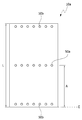
- the 1/4, 3/4, 3/8 or 7/8 point is the total length measured based on any one end surface E of the lower plate or the like, as shown in FIG. L) is the ratio of the distance A to the formation position of the hole.
- the terminal (E) in which the length (L) and the distance (A) are formed in the above may be any terminal (E) as long as the length (L) and the distance (A) are measured from the same terminal (E). have.
- the injection hole 50a is located at an approximately middle portion of the lower plate 10a.
- the size and shape of the injection hole are not particularly limited and can be formed in consideration of the injection efficiency of the resin layer material described later.
- the hole may be polygonal or amorphous, such as a circle, an oval, a triangle or a rectangle.
- the number and spacing of the injection holes are not particularly limited, and as described above, the resin layer may be adjusted to have a wide contact area with the lower plate.
- Observation holes may be formed at the end of the lower plate on which the injection hole is formed.
- the observation hole may be for observing whether the injected material is well injected to the end of the side wall, the lower plate or the upper plate when the resin layer material is injected through the injection hole.
- the position, shape, size, and number of the observation holes are not limited as long as they are formed to confirm that the injected material is properly injected.
- the module case may be a thermally conductive case.
- thermally conductive case means a case in which the thermal conductivity of the entire case is 10 W / mk or more, or at least includes a portion having such thermal conductivity.
- at least one of the above-described sidewalls, bottom plate and top plate may have the thermal conductivity described above.
- at least one of the sidewall, the bottom plate, and the top plate may include a portion having the thermal conductivity.
- the thermal conductivity is, in another example, 20 W / mk or more, 30 W / mk or more, 40 W / mk or more, 50 W / mk or more, 60 W / mk or more, 70 W / mk or more, 80 W / mk or more , 90 W / mk or more, 100 W / mk or more, 110 W / mk or more, 120 W / mk or more, 130 W / mk or more, 140 W / mk or more, 150 W / mk or more, 160 W / mk or more, 170 W / mk or more, 180 W / mk or more, 190 W / mk or more, or 195 W / mk or more.
- the thermal conductivity is about 1,000 W / mK or less, 900 W / mk or less, 800 W / mk or less, 700 W / mk or less, 600 W / mk or less, 500 W / mk or less, 400 W / mk or less, It may be 300 W / mk or 250 W / mK or less, but is not limited thereto.
- the kind of the material which exhibits the above thermal conductivity is not particularly limited, and examples thereof include metal materials such as aluminum, gold, pure silver, tungsten, copper, nickel or platinum.
- the module case may be entirely made of such a thermally conductive material, or at least a part of the module case may be a portion of the thermally conductive material. Accordingly, the module case may have a thermal conductivity in the above-mentioned range, or may include at least a portion having the above-mentioned thermal conductivity.
- a portion having thermal conductivity in the above range may be a portion in contact with a resin layer and / or an insulating layer, which will be described later.
- the portion having the thermal conductivity may be a portion in contact with a cooling medium such as cooling water. According to this structure, a structure capable of effectively dissipating heat generated from the battery cell to the outside may be implemented.
- the physical properties may be physical properties measured at room temperature.
- room temperature may refer to any temperature in the range of about 10 ° C. to 30 ° C., for example, about 25 ° C., about 23 ° C., or about 20 ° C.
- the type of battery cell accommodated in the module case is not particularly limited, and various known battery cells may be applied.
- the battery cell may be a pouch type.
- the pouch-type battery cell 100 may typically include an electrode assembly, an electrolyte, and a pouch sheath.
- FIG. 4 is an exploded perspective view schematically illustrating the configuration of an exemplary pouch-type cell
- FIG. 5 is a combined perspective view of the configuration of FIG. 4.
- the electrode assembly 110 included in the pouch-type cell 100 may have a form in which one or more positive electrode plates and one or more negative electrode plates are disposed between the separators.
- the electrode assembly 110 may be divided into a winding type in which one positive electrode plate and one negative electrode plate are wound together with a separator, or a plurality of positive electrode plates and a plurality of negative electrode plates alternately stacked with a separator interposed therebetween.
- the pouch packaging material 120 may be configured to include, for example, an outer insulating layer, a metal layer, and an inner adhesive layer.
- the exterior member 120 may include a metal thin film such as aluminum in order to protect internal elements such as the electrode assembly 110 and the electrolyte, and to compensate for the electrochemical properties of the electrode assembly 110 and the electrolyte and to provide heat dissipation. Can be.
- the metal thin film may be interposed between an insulating layer formed of an insulating material in order to ensure electrical insulation between the electrode assembly 110 and other elements such as an electrolyte or other elements outside the battery 100.
- the exterior member 120 may include an upper pouch 121 and a lower pouch 122, and at least one of the upper pouch 121 and the lower pouch 122 may have a concave inner space I. This can be formed.
- the electrode assembly 110 may be accommodated in the internal space I of the pouch. Sealing portions S may be provided on the outer circumferential surfaces of the upper pouch 121 and the lower pouch 122, and the sealing portions S may be adhered to each other to seal an inner space in which the electrode assembly 110 is accommodated.
- Each electrode plate of the electrode assembly 110 includes an electrode tab, and one or more electrode tabs may be connected to the electrode lead.
- the electrode lead is interposed between the sealing portion S of the upper pouch 121 and the lower pouch 122 to be exposed to the outside of the exterior member 120, thereby functioning as an electrode terminal of the secondary battery 100.
- the shape of the pouch-type cell is one example, and the battery cell applied in the present application is not limited to the above kind. In the present application, various well-known pouch-type cells or other types of batteries may be applied as battery cells.
- the battery module of the present application may further include a resin layer.
- the term resin layer is a layer containing a resin component, and in one example, the resin layer may be an adhesive layer.
- the battery module includes the case and the battery cell, and may be in contact with any one of the side wall, the bottom plate or the top plate of the case. At this time, the side wall, the bottom plate or the top plate which is in contact with the resin layer may be the above-described heat conductive side wall, the bottom plate or the top plate.
- the contact means thermal contact, wherein the resin layer is in direct contact with the lower plate or the like, or other elements between the resin layer and the lower plate, for example, insulation described later.
- the other element may mean the state which does not prevent the transfer of heat from the said resin layer to the said lower board etc. In the above, not impeding the transfer of heat, even if there is another element (eg an insulating layer or a guiding part described later) between the resin layer and the lower plate, the overall thermal conductivity of the other element and the resin layer.
- another element eg an insulating layer or a guiding part described later
- the thermal conductivity of the thermal contact is 50 W / mK or less, 45 W / mk or less, 40 W / mk or less, 35 W / mk or less, 30 W / mk or less, 25 W / mk or less, 20 W / mk or less, 15 W / mk or less, 10 W / mK or less, 5 W / mK or less, 4.5 W / mK or less, or about 4.0 W / mK or less.
- Such thermal contact can be achieved by controlling the thermal conductivity and / or thickness of the other element, if such other element is present.
- the resin layer may be in contact with the lower plate or the like and may also be in contact with the battery cell.
- the contact between the battery cell and the resin layer is also the thermal contact described above.
- a module may be configured to accommodate more battery cells per unit volume. Accordingly, in the present application, it is possible to provide a battery module having a smaller size, light weight, and high power.
- the module may include a case 10 including a side wall 10b and a bottom plate 10a as shown in 6 and 7; It may have a form including a plurality of battery cells 20 stored in the case and the resin layer 30 in contact with (thermally contacted) both the battery cell 20 and the case 10.
- the lower plate and the like contacting with the resin layer 30 may be a thermally conductive lower plate and the like as described above.
- the contact area of the resin layer and the lower plate may be about 70% or more, about 75% or more, about 80% or more, about 85% or more, about 90% or more or about 95% or more relative to the total area of the lower plate or the like.
- the upper limit of the contact area is not particularly limited, and may be, for example, 100% or less or less than about 100%.
- the contact area may be a ratio of the contact area with respect to the thermally conductive portion, that is, the total area of the thermally conductive portion.
- the thermally conductive portion or the thermally conductive bottom plate may be a portion contacting a cooling medium such as cooling water. That is, as shown schematically in FIG. 6, heat (H) can be easily discharged to the lower plate by the above structure, and by contacting the lower plate or the like with the cooling medium (CW), even in a more simplified structure The heat can be released easily.
- a cooling medium such as cooling water
- the resin layer 30 may be in the form of a relatively thin layer, or may fill the inner space of the case 10 as shown in FIG. 7.
- the battery cell 20 may exist in a state of being inserted into the resin layer.
- the thickness of the resin layer may be, for example, in the range of about 100 ⁇ m to 5 mm or in the range of about 200 ⁇ m to 5 mm.
- an appropriate thickness can be set in consideration of this point.
- the thickness may be the thickness of the thinnest portion, the thickness of the thickest portion, or the average thickness of the resin layer.
- the surface 10a in contact with the resin layer 30 may guide the battery cell 20 stored therein.
- the guiding part 10d may exist.
- the shape of the guiding part 10d is not particularly limited, and an appropriate shape may be adopted in consideration of the shape of the battery cell to be applied, and the guiding part 10d is integrally formed with the lower plate. Or may be attached separately.
- the guiding part 10d may be formed using a thermally conductive material, for example, a metal material such as aluminum, gold, pure silver, tungsten, copper, nickel or platinum in consideration of the thermal contact described above.
- a gap sheet or an adhesive layer may exist between the battery cells 20 to be accommodated.
- the interleaver may serve as a buffer when charging and discharging the battery cell.
- the resin layer or the battery module to which the resin layer is applied may have at least one or more of physical properties described below. Each physical property mentioned later is independent and does not give priority to the physical property of any one, and the resin layer can satisfy
- the resin layer is a thermally conductive resin layer, the thermal conductivity of about 1.5 W / mK or more, about 2 W / mK or more, 2.5 W / mK or more, 3 W / mK or more, 3.5 W / mK or more or 4 It may be at least W / mK.
- the thermal conductivity is 50 W / mK or less, 45 W / mk or less, 40 W / mk or less, 35 W / mk or less, 30 W / mk or less, 25 W / mk or less, 20 W / mk or less, 15 W / mk Or less, 10 W / mK or less, 5 W / mK or less, 4.5 W / mK or less, or about 4.0 W / mK or less.
- the resin layer is a thermally conductive resin layer as described above, the lower plate, etc., to which the resin layer is attached, may have the above-described thermal conductivity of 10 W / mK or more.
- the portion of the module case showing the thermal conductivity may be a portion in contact with a cooling medium, for example, cooling water.
- the thermal conductivity of a resin layer is a numerical value measured according to ASTMD5470 standard or ISO 22007-2 standard, for example.
- the manner in which the thermal conductivity of the resin layer is in the above range is not particularly limited.
- the thermal conductivity of the resin layer can be adjusted through the use of the type and / or filler of the resin used in the resin layer.
- acrylic resins, urethane resins, and silicone resins have similar thermal conductivity to each other, and epoxy resins have superior thermal conductivity
- olefin resins are epoxy resins.
- the thermal resistance of the resin layer or the battery module to which the resin layer is applied in the battery module is 5 K / W or less, 4.5 K / W or less, 4 K / W or less, 3.5 K / W or less, 3 K / W or less, or about 2.8 K / W or less.
- the method of measuring the thermal resistance is not particularly limited. For example, it can measure according to ASTM D5470 standard or ISO 22007-2 standard.
- the resin layer may have an appropriate adhesive force in consideration of effective fixing of the battery cell, impact resistance and vibration resistance in the process of using the module.
- the resin layer has an adhesive force of about 1,000 gf / 10 mm or less, about 950 gf / 10 mm or less, about 900 gf / 10 mm or less, about 850 gf / 10 mm or less, about 800 gf / 10 mm or less, about 750 gf / 10 mm Or about 700 gf / 10 mm or less, about 650 gf / 10 mm or less, or about 600 gf / 10 mm or less.
- the adhesive force of the resin layer may be about 50 or more, about 70 gf / 10 mm or more, about 80 gf / 10 mm or more, or about 90 gf / 10 mm or more.
- the adhesive force may be a value measured at a peel rate of about 300 mm / min and a peel angle of 180 degrees.
- the adhesive force may be adhesive force to the module case that the resin layer is in contact. For example, when an insulating layer is formed between the lower plate and the resin layer in contact with the resin layer in the module case as described below, the adhesive force to the module case is the module case in which the insulating layer is formed. May be adhesion to.
- the adhesive force as described above can be secured, excellent adhesion to various materials, for example, a case or a battery cell included in the battery module may appear excellent.
- the battery module may be prevented from being peeled off due to volume change, change in the use temperature of the battery module, or curing shrinkage of the resin layer, etc. at the time of charging and discharging the battery cell, thereby ensuring excellent durability.
- Such adhesive force can be ensured by, for example, configuring the resin layer with an adhesive layer. That is, the adhesive force which a well-known adhesive material can exhibit is well known, What is necessary is just to select a material in consideration of such adhesive force.
- the resin layer is also subjected to a thermal shock test, for example, after a thermal shock test in which the cycle is repeated 100 times with one cycle of maintaining the temperature at 80 ° C. for 30 minutes and then maintaining the temperature at 80 ° C. for 30 minutes. It may be required to be formed so as not to be peeled or peeled from the module case or the battery cell of the module. For example, when the battery module is applied to a product that requires a long warranty period (about 15 years or more in the case of an automobile) such as an automobile, the above level of performance may be required to ensure durability.
- the resin layer may be an electrically insulating resin layer.
- the electrically insulating resin layer has an insulation breakdown voltage measured according to ASTM D149 of about 3 kV / mm or more, about 5 kV / mm or more, about 7 kV / mm or more, 10 kV / mm or more, 15 kV / mm or more 20 kV / mm or more.
- the resin layer is not particularly limited to exhibit excellent insulating properties, but considering the composition of the resin layer, it is about 50 kV / mm or less, 45 kV / mm or less, 40 kV / mm or less. , 35 kV / mm or less, 30 kV / mm or less.
- the dielectric breakdown voltage as described above can also be controlled by controlling the insulation of the resin component of the resin layer.
- the dielectric breakdown voltage can be adjusted by applying an insulating filler in the resin layer.
- the ceramic filler as described later is known as a component capable of ensuring insulation.
- a flame retardant resin layer may be applied in consideration of stability.
- the term flame retardant resin layer may refer to a resin layer having a V-0 rating in a UL 94 V Test (Vertical Burning Test). This ensures stability against fire and other accidents that may occur in the battery module.
- the resin layer may have a specific gravity of 5 or less.
- the specific gravity may be 4.5 or less, 4 or less, 3.5 or less, or 3 or less.
- the resin layer exhibiting specific gravity in this range is advantageous for the production of a lighter battery module.
- the specific gravity may be about 1.5 or more or 2 or more.
- components added to the resin layer may be adjusted. For example, when the thermally conductive filler is added, a filler capable of securing the desired thermal conductivity even at the lowest specific gravity, that is, a filler having a low specific gravity or a surface-treated filler may be used. have.
- the resin layer does not contain a volatile substance if possible.
- the resin layer may have a ratio of nonvolatile content of 90 wt% or more, 95 wt% or more, or 98 wt% or more.
- the nonvolatile component and its ratio may be defined in the following manner. That is, the non-volatile portion may be defined as the non-volatile content of the remaining portion after maintaining the resin layer at 100 ° C for about 1 hour, and thus the ratio is maintained for about 1 hour at the initial weight of the resin layer and the 100 ° C It can measure based on a later ratio.
- the resin layer may have excellent resistance to deterioration as necessary, but stability may be required in which the surface of the module case or the battery cell does not react as chemically as possible.
- the resin layer also has a low shrinkage rate after curing or after curing. Through this, it is possible to prevent peeling or the generation of voids that may occur during the manufacture or use of the module.
- the shrinkage rate may be appropriately adjusted in a range capable of exhibiting the above-described effects, for example, may be less than 5%, less than 3% or less than about 1%. Since the said shrinkage rate is so advantageous that the numerical value is low, the minimum in particular is not restrict
- the resin layer also has a low coefficient of thermal expansion (CTE).
- CTE coefficient of thermal expansion
- the coefficient of thermal expansion can be appropriately adjusted in a range capable of exhibiting the above-described effects, for example, less than 300 ppm / K, less than 250 ppm / K, less than 200 ppm / K, less than 150 ppm / K or about 100 may be less than ppm / K. Since the said coefficient of thermal expansion is so advantageous that the numerical value is low, the minimum in particular is not restrict
- Tensile strength of the resin layer can be appropriately adjusted, through which excellent impact resistance and the like can be secured to provide a module showing appropriate durability.
- Tensile strength can be adjusted, for example, in the range of about 1.0 MPa or more.
- Elongation of the resin layer can be appropriately adjusted, through which excellent impact resistance and the like can be secured, it is possible to provide a module showing appropriate durability. Elongation can be adjusted, for example, in the range of at least about 10% or at least about 15%.
- the resin layer also exhibits an appropriate hardness. For example, if the hardness of the resin layer is too high, the resin layer may be too brittle and adversely affect the reliability. In addition, by controlling the hardness of the resin layer it is possible to ensure impact resistance, vibration resistance, and ensure the durability of the product.
- the resin layer may, for example, have a hardness in Shore A type of less than 100, 99 or less, 98 or less, 95 or less, or 93 or less, or hardness in Shore D type of less than about 80, about 70 or less, or about 65 or less or about 60 or less.
- the lower limit of the hardness is not particularly limited.
- the hardness may be about 60 or more in Shore A type, or about 5 or about 10 or more in Shore OO type.
- the hardness of a resin layer is normally influenced by the kind or ratio of the filler contained in the resin layer, and when an excess filler is included, hardness will usually become high.
- the resin component contained in the resin layer also affects the hardness, as silicone-based resins generally exhibit lower hardness than other resins such as epoxy or urethane.
- the resin layer may also have a 5% weight loss temperature in the thermogravimetric analysis (TGA) of at least 400 ° C., or a residual amount of 800 ° C. at least 70% by weight. This characteristic can further improve stability at high temperatures of the battery module.
- the remaining 800 ° C. may be at least about 75 wt%, at least about 80 wt%, at least about 85 wt%, or at least about 90 wt%, in another example.
- the residual amount of 800 ° C. may be about 99 wt% or less in another example.
- the thermogravimetric analysis (TGA) can be measured within a range of 25 ° C. to 800 ° C.
- thermogravimetric analysis (TGA) results can also be achieved through control of the composition of the resin layer.
- the residual amount of 800 ° C is usually influenced by the type or proportion of the filler contained in the resin layer, and when the excess filler is included, the remaining amount increases.
- the silicone resin generally has higher heat resistance than other resins such as epoxy or urethane, the remaining amount is higher, and thus the resin component contained in the resin layer also affects its hardness.
- the type of the resin layer is not particularly limited as long as it can effectively fix the battery cell, and the above-mentioned physical properties can be imparted as necessary, and all known curable resin materials can be used.
- the material that can be used include acrylic resins, epoxy resins, urethane resins, olefin resins, urethane resins, EVA (Ethylene vinyl acetate) resins, silicone resins, and the like, and thus the resin layer includes the resins. can do.
- the said resin layer can contain the said resin as a main component in a resin component.
- the acrylic resin about 70% of the acrylic resin, epoxy resin, urethane resin, olefin resin, urethane resin, EVA (Ethylene vinyl acetate) resin or silicone resin among the total resin components included in the resin layer. At least about 75%, at least about 80%, at least about 85%, or at least about 90%. The ratio may be about 99% or less or about 95% or less.
- the material for forming the resin layer may be an adhesive material as described above, and may be a solvent type, an aqueous type, or a solventless type, but may be appropriately a solventless resin layer in consideration of convenience of the manufacturing process described later. Can be.
- the resin layer material may be an active energy ray curing type, a moisture curing type, a thermosetting type or a room temperature curing type, or the like, and may be appropriate to be a room temperature curing type in consideration of the convenience of the manufacturing process described later.
- the resin layer may include a filler in consideration of the above-described thermal conductivity, insulation, heat resistance (TGA analysis) or specific gravity.
- the filler may be a thermally conductive filler.
- thermally conductive filler means a material having a thermal conductivity of about 1 W / mK or more, about 5 W / mK or more, about 10 W / mK or more, or about 15 W / mK or more.
- the thermal conductivity of the thermally conductive filler may be about 400 W / mK or less, about 350 W / mK or less or about 300 W / mK or less.
- thermally conductive filler that can be used is not particularly limited, but a ceramic filler may be applied in consideration of insulation properties and the like.
- ceramic particles such as alumina, aluminum nitride (AlN), boron nitride (BN), silicon nitride, ZnO, SiC, or BeO may be used.
- carbon fillers such as graphite can also be considered.
- the form or ratio of the filler contained in the resin layer is not particularly limited and is selected in consideration of the viscosity of the resin composition, the possibility of sedimentation in the resin layer, the desired thermal resistance or thermal conductivity, insulation, filling effect or dispersibility, and the like.
- the resin layer may include a thermally conductive filler having an average particle diameter in the range of 0.001 ⁇ m to 80 ⁇ m.
- the average particle diameter of the filler may be 0.01 ⁇ m or more, 0.1 or more, 0.5 ⁇ m or more, 1 ⁇ m or more, 2 ⁇ m or more, 3 ⁇ m or more, 4 ⁇ m or more, 5 ⁇ m or more, or about 6 ⁇ m or more.
- the average particle diameter of the filler is, in another example, about 75 ⁇ m or less, about 70 ⁇ m or less, about 65 ⁇ m or less, about 60 ⁇ m or less, about 55 ⁇ m or less, about 50 ⁇ m or less, about 45 ⁇ m or less, about 40 ⁇ m or less, about 35 ⁇ m or less, about 30 ⁇ m or less, about 25 ⁇ m or less, about 20 ⁇ m or less, about 15 ⁇ m or less, about 10 ⁇ m or less, or about 5 ⁇ m or less.
- the ratio of the filler contained in the resin layer may be selected in consideration of the properties of the resin layer so that the above-described properties, for example, thermal conductivity, insulation, and the like can be secured.
- the filler may be included in the range of about 50 to 2,000 parts by weight relative to 100 parts by weight of the resin component of the resin layer.
- the weight part of the filler in another example is about 100 parts by weight or more, about 150 parts by weight or more, about 200 parts by weight or more, about 250 parts by weight or more, about 300 parts by weight or more, about 350 parts by weight or more, about 400 parts by weight or more, At least about 500 parts by weight, at least about 550 parts by weight, at least about 600 parts by weight or at least about 650 parts by weight.
- the resin layer may be a viscosity modifier such as a thixotropic agent, a diluent, a dispersant, a surface treatment agent or a coupling agent to adjust the viscosity as necessary, for example to increase or decrease the viscosity or to adjust the viscosity according to shear force. And the like may be further included.
- a viscosity modifier such as a thixotropic agent, a diluent, a dispersant, a surface treatment agent or a coupling agent to adjust the viscosity as necessary, for example to increase or decrease the viscosity or to adjust the viscosity according to shear force. And the like may be further included.
- the thixotropic agent may adjust the viscosity according to the shear force of the resin composition so that the manufacturing process of the battery module is effectively performed.
- examples of the thixotropic agent that can be used include fumed silica and the like.
- Diluents or dispersants are generally used for lowering the viscosity of the resin composition, and any one of various kinds known in the art can be used without limitation as long as the diluent or dispersant is capable of exhibiting the above functions.
- the surface treating agent is for surface treatment of the filler introduced into the resin layer, and various kinds known in the art can be used without limitation as long as it can exhibit the above-described action.
- the coupling agent for example, it can be used to improve the dispersibility of a thermally conductive filler such as alumina, and various kinds known in the art can be used without limitation as long as it can exhibit the above action.
- the resin layer may further include a flame retardant or a flame retardant aid.
- a resin layer can form a flame-retardant resin layer.
- various flame retardants known in the art may be applied without particular limitation.
- a solid filler type flame retardant or a liquid flame retardant may be applied.
- Flame retardants include, for example, organic flame retardants such as melamine cyanurate, inorganic flame retardants such as magnesium hydroxide, and the like, but is not limited thereto.
- a liquid type flame retardant material TEP, Triethyl phosphate or TCPP, tris (1,3-chloro-2-propyl) phosphate, etc.
- TEP Triethyl phosphate
- TCPP tris (1,3-chloro-2-propyl) phosphate
- silane coupling agent may be added that can act as a flame retardant synergist.
- the resin layer may contain any one or two or more of the above components.
- the battery module may further include an insulating layer between the module case and the battery cell or between the resin layer and the module case.
- FIG. 8 shows an example in which the insulating layer 40 is formed between the resin layer 30 and the guiding portion 10d formed on the lower plate 10c of the case.
- the insulating layer may be formed using an insulating sheet having high insulation and thermal conductivity, or may be formed by coating or injecting a material exhibiting insulation. For example, in the method of manufacturing a battery module described below, a process of forming an insulating layer may be performed before the injection of the resin composition.
- the insulating layer may be formed of an adhesive material, and for example, the insulating layer may be formed using a resin layer having little or no filler such as a thermally conductive filler.
- the resin component that can be used to form the insulating layer include acrylic resins, olefin resins such as PVC (poly (vinyl chloride)) and PE (polyethylene), epoxy resin, silicone, and EPDM rubber (ethylene propylene diene monomer rubber). Rubber components, such as, but not limited to, etc.
- the insulating layer has an insulation breakdown voltage measured in accordance with ASTM D149 of about 5 kV / mm or more, about 10 kV / mm or more, about 15 kV / kmm or more, 20 kV / mm or more, 25 kV / mm or more or 30 kV / mm or more
- the breakdown voltage is not particularly limited as the value shows higher insulation.
- the dielectric breakdown voltage of the insulating layer may be about 100 kV / mm or less, 90 kV / mm or less, 80 kV / mm or less, 70 kV / mm or less, or 60 kV / mm or less. It can be set in an appropriate range in consideration of insulation and thermal conductivity.
- it may be about 5 ⁇ m or more, about 10 ⁇ m or more, 20 ⁇ m or more, 30 ⁇ m or more, 40 ⁇ m or more, 50 ⁇ m or more, 60 ⁇ m or more, 70 ⁇ m or more, 80 ⁇ m or more or 90 ⁇ m or more.
- the upper limit of the thickness is not particularly limited, and may be, for example, about 1 mm or less, about 200 ⁇ m or less, 190 ⁇ m or less, 180 ⁇ m or less, 170 ⁇ m or less, 160 ⁇ m or less, or 150 ⁇ m or less.
- the present application also relates to a method for manufacturing a battery module, for example the battery module mentioned above.
- Manufacturing method of the present application the step of injecting the resin composition in the above-described module case; And storing the battery cell in the module case and curing the resin composition to form the resin layer.
- the order of injecting the resin composition into the module case and accommodating the battery cells in the module case are not particularly limited.
- the resin composition may be first injected into the module case, and the battery cell may be stored in that state, or the resin composition may be injected after the battery cell is first stored inside the module case.
- resin composition in this application means the state of the resin layer before hardening
- resin layer can mean the state of the resin layer after hardening
- the method of injecting the resin composition into the module case is not particularly limited, and a known method may be applied.
- the resin composition is poured into the opening of the module case to inject the resin composition, or the resin composition is injected through the above-described injection hole formed in the module case, and the resin composition is injected into both the battery cell and the battery module.
- the method of coating may be applied.
- the implantation process may be performed while constantly vibrating the battery module or battery cell for proper fixation.
- the kind of resin composition injected above is not restrict
- the resin composition injected above may be a resin composition capable of satisfying the above-described physical properties such as thermal conductivity or forming a resin layer containing a component therefor.
- Such a resin composition may be the above-described solvent type, aqueous or solvent-free resin composition, and may be suitably a solvent-free resin composition.
- the resin composition may be an active energy ray-curable, moisture-curable, thermosetting or room temperature curing type resin composition, or the like, and may be suitably room temperature curing type resin composition.
- the resin composition may be a resin composition including at least one of various additives such as the above-described thermal conductive filler.
- Such a resin composition may be composed of one-component, two-component, or three-component.
- the manner in which the battery cells are housed in the module case in which the resin composition is injected or in the module case before the composition is injected is not particularly limited.
- the storage of the battery cells can be performed by arranging the battery cells at suitable positions in the module case in consideration of the desired arrangement and the like.
- the above steps may be performed by positioning the battery cell at a proper position of the cartridge structure, or inserting the cartridge structure in which the battery cell is located in the module case.
- the adhesion between the battery cells or the adhesion between the battery cells and the module case may be formed by curing the injected resin composition.
- the manner of curing the resin composition is not particularly limited.
- the resin composition is an active energy ray-curable type
- a method of irradiating active energy rays such as ultraviolet rays to the resin composition a method of keeping it under appropriate moisture when it is a moisture curable type, and applying appropriate heat in the case of a thermosetting type.
- the above steps may be performed by maintaining the resin composition at room temperature.
- a short time heat may be applied to a temperature of about 40 ° C. to about 50 ° C. under conditions that do not affect the stability of the battery cell in terms of tack time and fairness before curing or before storage or storage of the battery cell. It may be.
- the present application also relates to a resin composition that can be used to form the above manufacturing method or the battery module of the aforementioned structure.
- the resin composition is not particularly limited as long as it can effectively fix the battery cell to the module case, and if the above-mentioned physical properties can be imparted as necessary, all known resin compositions can be used. .
- Such resin compositions include, but are not limited to, acrylic resin compositions, epoxy resin compositions, urethane resin compositions, olefin resin compositions, urethane resin compositions, EVA (Ethylene vinyl acetate) resin compositions or silicone resin compositions. .
- the resin composition may be a solvent-type resin composition, an aqueous resin composition or a solvent-free resin composition, and may be a solvent-free resin composition as appropriate.
- the resin composition may be an active energy ray curable resin composition, a moisture curable resin composition, a thermosetting resin composition, a room temperature curable resin composition, or the like, and may be an ambient temperature curable resin composition.
- the additives such as the above-mentioned filler
- the resin composition which can form a well-known acrylic adhesive, an epoxy adhesive, a urethane adhesive, an olefin adhesive, an EVA (Ethylene vinyl acetate) adhesive, or a silicone adhesive.
- a suitable amount can be applied to the above-described method.
- the resin composition as described above may include a radical initiator and a catalyst thereof in consideration of room temperature curability and the like.
- the resin composition may comprise an acyl peroxide initiator such as benzoyl peroxide and the like and a catalyst for such an initiator such as a toluidine compound, whereby a suitable curing system can be implemented.
- the resin composition may further include various components as necessary in addition to the above components.
- the present application also relates to a battery pack, for example, a battery pack including two or more battery modules described above.
- the battery modules may be electrically connected to each other.
- the method of configuring the battery pack by electrically connecting two or more battery modules is not particularly limited, and all known methods may be applied.
- the present application also relates to a device including the battery module or the battery pack.
- a device including the battery module or the battery pack examples include, but are not limited to, automobiles such as electric vehicles, and may include all applications requiring a secondary battery as an output.
- a method of configuring the vehicle using the battery module or the battery pack is not particularly limited, and a general method may be applied.
- the present application may provide a battery module having excellent output to volume, excellent heat dissipation characteristics, etc. while being manufactured at a simple process and low cost, a manufacturing method thereof, and a resin composition applied to the manufacturing method.
- FIG. 1 is a view showing an exemplary module case that can be applied in the present application.
- FIG. 2 is a view illustrating a battery cell housed in a module case.
- FIG 3 is a view of an exemplary bottom plate in which an injection hole and an observation hole are formed.
- FIGS. 4 and 5 illustrate exemplary battery pouches that can be used as battery cells.
- 6 to 8 show the structure of an exemplary battery module.
- the thermal conductivity of the resin layer was measured according to the ASTM D5470 standard. That is, after placing the resin layer between two copper bars according to the specification of ASTM D 5470, one of the two copper bars is in contact with the heater and the other is in contact with the cooler. The heater was kept at a constant temperature and the capacity of the cooler was adjusted to create a thermal equilibrium (state showing a temperature change of about 0.1 ° C. or less in 5 minutes). The temperature of each copper rod was measured in the thermal equilibrium state, and thermal conductivity (K, unit: W / mK) was evaluated according to the following formula. When the thermal conductivity was evaluated, the pressure applied to the resin layer was adjusted to about 11 Kg / 25 cm 2, and the thermal conductivity was calculated based on the final thickness when the thickness of the resin layer was changed during the measurement.
- K thermal conductivity (W / mK)
- Q heat transferred per unit time (unit: W)
- dx thickness of resin layer (unit: m)
- A is cross-sectional area of resin layer (unit: m2)
- dT is the temperature difference (unit: K) of the copper rod.
- Specific gravity of the resin layer was measured according to the ASTM D792 standard. For example, after weighing the resin layer in accordance with the standard, and weighed again in water, the density and specific gravity are calculated from the measured weight difference, or a predetermined amount of powder or pellet (ex. About 5 g ) Into the already measured volume in the pyrometer and the specific gravity can be calculated from the difference in weight and volume at 73.4 F °.
- Thermogravimetric analysis was performed using TA Instrument's TA400 instrument. The analysis was performed using about 10 mg of the resin layer, and the analysis was performed under a nitrogen (N 2) atmosphere of a temperature range of 25 ° C. to 800 ° C., a heating rate of 20 ° C./min, and 60 cm 3 / min.
- N 2 nitrogen
- the dielectric breakdown voltage of the resin layer was evaluated according to ASTM D149 standard.
- the dielectric breakdown voltage refers to a voltage applied to the moment when the material loses insulation, and at high voltages above a certain level, the conductivity rapidly increases and loses insulation.
- the minimum voltage required to cause dielectric breakdown is called the breakdown voltage, and insulation is created through the arc through the specimen.
- the voltage gradient can be obtained by dividing the voltage at the instant of breakdown by the insulation thickness.
- the breakdown voltage was measured using the Backman Industrial PA70-1005 / 202 instrument. At this time, the thickness of the specimen (resin layer) was about 2 mm and the diameter was about 100 mm.
- the attachment is performed by curing the uncured resin composition after loading between the insulating film and the PET film. Thereafter, the adhesive force is measured while peeling the PET film from the insulating side at a speed of about 300 mm / min and a peel angle of 180 degrees.
- the hardness of the resin layer was measured in accordance with ASTM D 2240 and JIS K 6253 standards. ASKER, durometer hardness was performed using the instrument, the initial hardness was measured by applying a load (about 1.5 Kg) of more than 1 Kg to the surface of the flat sample (resin layer), and after 15 seconds confirmed by the stabilized measured value hardness Was evaluated.
- the reliability of the battery module was evaluated by measuring the thermal resistance and withstand voltage strength of the module. Withstand voltage strength is a test to see how much voltage is applied to the battery module without damage. In the following examples and comparative examples, the breakdown voltage strength was measured while increasing the magnitude of the applied voltage starting at about 1.2 kV.
- the thermal resistance of the battery module is input by placing the module between the upper and lower blocks of the measuring device, running the DynTIM Tester software of the controlling computer, and determining the heating current and the measuring time on the software. After setting the parameters such as measurement pressure and thermal resistance measurement conditions, the T3Ster and DynTIM tester controlled by software were measured for the thermal resistance value for each measurement condition, and the thermal resistance was evaluated. Reliability according to each evaluation result was classified by the following criteria.
- Alumina particle size distribution: 1 ⁇ m to 60 ⁇ m
- a two-component urethane adhesive composition (subject: HP-3753 (KPX Chemical), a curing agent: TLA-100 (made by Asaika)), and the cured adhesive composition was about 3 after the two-component urethane adhesive composition was cured.
- a resin composition having a room temperature viscosity of about 250,000 cP is prepared, and the following battery It was applied to the manufacture of the module.
- a module case having a shape as shown in FIG. 1 a module case having a lower plate, a side wall, and an upper plate made of aluminum was used.
- the inner surface of the lower plate of the module case is formed with a guiding part for guiding the mounting of the battery cell, the injection hole for the injection of the resin composition is formed at a predetermined interval in the center of the lower plate of the module case, An observation hole is formed at the end.
- a bundle of pouches in which a plurality of battery pouches were stacked was stored in the module case.
- the top plate was then covered on the upper surface of the module case. Thereafter, the prepared resin composition was injected into the injection hole until it was confirmed that the injected composition reached the observation hole, and then cured to prepare a battery module.
- Alumina particle size distribution: 1 ⁇ m to 60 ⁇ m
- a two-component silicone adhesive composition subject: SL5100A (manufactured by KCC) and a curing agent: SL5100B (manufactured by KCC)
- SL5100A manufactured by KCC
- SL5100B manufactured by KCC
- thermal conductivity within the range of about 800 to 1200 parts by weight relative to 100 parts by weight of the total amount of two liquids
- a resin composition having a room temperature viscosity of about 130,000 cP is prepared, which is used to prepare the following battery module. Applied.
- a case having the same structure as that used in Example 1 but not having an injection hole and an observation hole for injection of the resin composition was used.
- the prepared resin composition is coated on the entire inner surface of the lower plate of the case to a thickness of about 500 ⁇ m, and the same battery cell as in Example 1 is stored, and after the top plate is covered, the layer of the resin composition is cured to form a battery module. Prepared.
- Alumina particle size distribution: 1 ⁇ m to 60 ⁇ m
- a two-component urethane adhesive composition subject: PP-2000 (KPX Chemical), a curing agent: TLA-100 (manufactured by Asaika)
- PP-2000 KPX Chemical
- TLA-100 manufactured by Asaika
- Alumina particle size distribution: 1 ⁇ m to 60 ⁇ m
- the adhesive composition exhibited a thermal conductivity of about 3 W / mK after curing (2 liquid total solids 100
- Battery modules were prepared in the same manner as in Example 1, except that a resin composition prepared in a range of about 600 to 900 parts by weight relative to parts by weight was used so that the room temperature viscosity was about 500,000 cP.
- Graphite was added to the two-component silicone adhesive composition (subject: SL5100A (manufactured by KCC), the curing agent: SL5100B (manufactured by KCC)), and the amount of thermal conductivity of about 1.5 W / mK after the two-component silicone adhesive composition was cured.
- the battery module was prepared in the same manner as in Example 2 except that the resin composition was prepared by mixing in a range of about 100 to 300 parts by weight with respect to 100 parts by weight of the total of 2 liquid solids, and having a room temperature viscosity of about 2,000,000 cP.) Prepared.
- Alumina particle size distribution: 1 ⁇ m to 60 ⁇ m
- a two-component silicone adhesive composition subject: SL5100A (manufactured by KCC), a curing agent: SL5100B (manufactured by KCC)
- the thermal conductivity about 1.5 W / mK after the adhesive composition was cured.
- a resin composition prepared by mixing in an amount that can be represented (in the range of about 300 to 500 parts by weight relative to 100 parts by weight of the total amount of two liquids) to have a room temperature viscosity of about 100,000 cP.
- Alumina particle size distribution: 1 ⁇ m to 60 ⁇ m
- a two-component urethane adhesive composition subject: PP-2000 (KPX Chemical), a curing agent: TLA-100 (manufactured by Asaika)
- PP-2000 KPX Chemical
- TLA-100 curing agent
- a resin composition prepared by mixing in an amount capable of exhibiting thermal conductivity of W / mK (within a range of about 400 to 900 parts by weight relative to 100 parts by weight of 2 liquid total solids) to have a room temperature viscosity of about 150,000 cP.
- a battery module in the same manner as in Example 1.
- a battery module was manufactured in the same manner as in Example 2, except that no adhesive composition was used, that is, no resin layer was formed.
- Example Comparative example One 2 3 4 5 6 7 One Resin layer Thermal Conductivity (W / mK) 3 3 3.5 3 1.5 1.5 2 - importance 3.1 3.1 3.2 3.2 2 2 2.6 - Residue at 800 ° C (% by weight) > 80 > 80 > 80 > 80 > 80 About 60 About 60 About 50 - Adhesive force (gf / 10mm) 500 100 450 600 80 90 500 - Hardness (shore A) 90 60 90 100 40 40 70 - Breakdown voltage (kV / mm) 15 11 10 ⁇ 8 2 5 4 - Reliability (withstand voltage strength) Prize Prize Prize medium medium medium medium medium Ha Reliability (thermal resistance) Prize Prize Prize medium medium medium medium Ha
- Example 7 when comparing the results of Examples 2, 5 and 6 or the results of Examples 1, 3, 7, when the same series of resins were used, the thermal conductivity, specific gravity and heat resistance (TGA analysis) As a result, it can be confirmed that hardness and the like change. For example, in Example 7, a smaller amount of filler was applied as compared to Examples 1 and 3, resulting in somewhat lower thermal conductivity and specific gravity, lower thermal resistance (TGA analysis), and similar adhesion strength. However, the hardness was slightly lowered, and the dielectric breakdown voltage was lowered, in particular, due to the decrease in the proportion of the fillers that influenced to ensure insulation. Accordingly, it can be confirmed that Example 7 is somewhat inferior in the reliability evaluation results compared to Examples 1 and 3.
Landscapes
- Chemical & Material Sciences (AREA)
- Chemical Kinetics & Catalysis (AREA)
- General Chemical & Material Sciences (AREA)
- Electrochemistry (AREA)
- Engineering & Computer Science (AREA)
- Manufacturing & Machinery (AREA)
- Organic Chemistry (AREA)
- Medicinal Chemistry (AREA)
- Health & Medical Sciences (AREA)
- Polymers & Plastics (AREA)
- Mechanical Engineering (AREA)
- Life Sciences & Earth Sciences (AREA)
- Transportation (AREA)
- Power Engineering (AREA)
- Sustainable Energy (AREA)
- Sustainable Development (AREA)
- Materials Engineering (AREA)
- Battery Mounting, Suspending (AREA)
- Secondary Cells (AREA)
- Sealing Battery Cases Or Jackets (AREA)
Abstract
Description
| 실시예 | 비교예 | ||||||||
| 1 | 2 | 3 | 4 | 5 | 6 | 7 | 1 | ||
| 수지층 | 열전도도(W/mK) | 3 | 3 | 3.5 | 3 | 1.5 | 1.5 | 2 | - |
| 비중 | 3.1 | 3.1 | 3.2 | 3.2 | 2 | 2 | 2.6 | - | |
| Residue at 800℃(중량%) | >80 | >80 | >80 | >80 | 약60 | 약60 | 약50 | - | |
| 접착력(gf/10mm) | 500 | 100 | 450 | 600 | 80 | 90 | 500 | - | |
| 경도(shore A) | 90 | 60 | 90 | 100 | 40 | 40 | 70 | - | |
| 절연파괴전압(kV/mm) | 15 | 11 | 10 | < 8 | 2 | 5 | 4 | - | |
| 신뢰성(내전압 강도) | 상 | 상 | 상 | 중 | 중 | 중 | 중 | 하 | |
| 신뢰성(열저항) | 상 | 상 | 상 | 중 | 중 | 중 | 중 | 하 | |
Claims (20)
- 내부 공간을 형성하는 하부판과 측벽을 가지는 모듈 케이스; 상기 모듈 케이스의 내부 공간에 존재하는 복수의 배터리셀; 및 상기 모듈 케이스의 내부 공간에 존재하는 수지층을 포함하고,상기 수지층은, 상기 복수의 배터리셀과 접촉하고 있고, 또한 상기 모듈 케이스의 하부판 또는 측벽과 접촉하고 있는 배터리 모듈.
- 제 1 항에 있어서, 수지층과 접촉하고 있는 하부판 또는 측벽에는 수지 조성물 주입홀이 형성되어 있는 배터리 모듈.
- 제 2 항에 있어서, 주입홀이 형성되어 있는 측벽 또는 하부판에는 관찰홀이 형성되어 있는 배터리 모듈.
- 제 1 항에 있어서, 수지층과 접촉하고 있는 측벽 또는 하부판은 열전도성 영역을 포함하는 배터리 모듈.
- 제 4 항에 있어서, 수지층과 열전도성 영역의 접촉 비율은, 상기 열전도성 영역의 전체 면적 대비 80% 이상인 배터리 모듈.
- 제 1 항에 있어서, 수지층은 열전도도가 1.5 W/mK 이상인 배터리 모듈.
- 제 1 항에 있어서, 수지층은 절연 파괴 전압이 10 kV/mm 이상인 배터리 모듈.
- 제 1 항에 있어서, 수지층은, 접착력이 1,000 gf/10mm 이하인 배터리 모듈.
- 제 1 항에 있어서, 수지층은, 비중이 5 이하인 배터리 모듈.
- 제 1 항에 있어서, 수지층은 쇼어 A 경도가 100 미만이거나, 쇼어 D 경도가 70 이하인 배터리 모듈.
- 제 1 항에 있어서, 수지층은, 열중량분석(TGA)에서 800℃ 잔량이 70 중량% 이상인 배터리 모듈.
- 제 1 항에 있어서, 수지층은, 아크릴 수지, 에폭시 수지, 우레탄 수지, 올레핀 수지, EVA 수지 또는 실리콘 수지를 포함하는 배터리 모듈.
- 제 1 항에 있어서, 수지층은 필러를 포함하는 배터리 모듈.
- 제 13 항에 있어서, 필러는, 세라믹 입자 또는 탄소계 필러인 배터리 모듈.
- 제 1 항에 있어서, 수지층은, 요변성 부여제, 희석제, 분산제, 표면 처리제, 난연제 또는 커플링제를 포함하는 배터리 모듈.
- 제 1 항에 있어서, 수지층은, 두께가 100㎛ 내지 5 mm의 범위 내인 배터리 모듈.
- 내부 공간을 형성하는 하부판과 측벽을 가지는 모듈 케이스 내에 수지 조성물을 주입하는 단계; 상기 모듈 케이스 내에 배터리셀을 수납하는 단계 및 상기 수지 조성물을 경화시켜 수지층을 형성하는 단계를 포함하는 배터리 모듈의 제조 방법.
- 제 17 항에 있어서, 하부판 또는 측벽에는 수지 조성물 주입홀이 형성되어 있고, 수지 조성물은, 배터리셀을 수납한 후에 상기 주입홀로 주입하는 배터리 모듈의 제조 방법.
- 서로 전기적으로 연결되어 있는, 제 1 항의 배터리 모듈을 2개 이상 포함하는 배터리팩.
- 제 1 항에 배터리 모듈 또는 제 20 항의 배터리팩을 포함하는 자동차.
Priority Applications (7)
| Application Number | Priority Date | Filing Date | Title |
|---|---|---|---|
| JP2017545296A JP6681911B2 (ja) | 2015-02-27 | 2016-02-29 | バッテリーモジュール |
| CN202011215020.2A CN112531255B (zh) | 2015-02-27 | 2016-02-29 | 电池模块 |
| US15/553,336 US10615470B2 (en) | 2015-02-27 | 2016-02-29 | Battery module |
| CN201680012582.2A CN107431147B (zh) | 2015-02-27 | 2016-02-29 | 电池模块 |
| CN202010588590.XA CN111799411B (zh) | 2015-02-27 | 2016-02-29 | 电池模块 |
| EP16755953.3A EP3264492B1 (en) | 2015-02-27 | 2016-02-29 | Battery module |
| US16/790,033 US11271264B2 (en) | 2015-02-27 | 2020-02-13 | Battery module |
Applications Claiming Priority (2)
| Application Number | Priority Date | Filing Date | Title |
|---|---|---|---|
| KR10-2015-0028505 | 2015-02-27 | ||
| KR20150028505 | 2015-02-27 |
Related Child Applications (2)
| Application Number | Title | Priority Date | Filing Date |
|---|---|---|---|
| US15/553,336 A-371-Of-International US10615470B2 (en) | 2015-02-27 | 2016-02-29 | Battery module |
| US16/790,033 Division US11271264B2 (en) | 2015-02-27 | 2020-02-13 | Battery module |
Publications (1)
| Publication Number | Publication Date |
|---|---|
| WO2016137303A1 true WO2016137303A1 (ko) | 2016-09-01 |
Family
ID=56788663
Family Applications (1)
| Application Number | Title | Priority Date | Filing Date |
|---|---|---|---|
| PCT/KR2016/002000 Ceased WO2016137303A1 (ko) | 2015-02-27 | 2016-02-29 | 배터리 모듈 |
Country Status (6)
| Country | Link |
|---|---|
| US (2) | US10615470B2 (ko) |
| EP (1) | EP3264492B1 (ko) |
| JP (2) | JP6681911B2 (ko) |
| KR (9) | KR101941117B1 (ko) |
| CN (3) | CN107431147B (ko) |
| WO (1) | WO2016137303A1 (ko) |
Cited By (21)
| Publication number | Priority date | Publication date | Assignee | Title |
|---|---|---|---|---|
| US20180205055A1 (en) * | 2016-04-03 | 2018-07-19 | Brammo, Inc. | Battery pack and method of manufacture |
| KR20180087370A (ko) * | 2016-11-02 | 2018-08-01 | 주식회사 엘지화학 | 배터리 시스템 |
| JP2018522373A (ja) * | 2015-06-12 | 2018-08-09 | エルジー・ケム・リミテッド | バッテリーモジュール |
| WO2018173860A1 (ja) * | 2017-03-22 | 2018-09-27 | 積水ポリマテック株式会社 | バッテリモジュールおよびバッテリパック |
| EP3419082A4 (en) * | 2016-04-01 | 2019-03-13 | LG Chem, Ltd. | BATTERY MODULE |
| CN109638374A (zh) * | 2017-10-05 | 2019-04-16 | 丰田自动车株式会社 | 电池组 |
| JP2019511829A (ja) * | 2016-10-10 | 2019-04-25 | エルジー・ケム・リミテッド | バッテリーモジュールアセンブリー |
| JP2019515480A (ja) * | 2017-01-17 | 2019-06-06 | エルジー・ケム・リミテッド | バッテリーモジュール、このバッテリーモジュールを含むバッテリーパック及びこのバッテリーパックを含む自動車 |
| JP2019515461A (ja) * | 2017-01-17 | 2019-06-06 | エルジー・ケム・リミテッド | バッテリーモジュールの製造方法 |
| CN110249477A (zh) * | 2017-09-18 | 2019-09-17 | 株式会社Lg化学 | 用于制造电池组的方法 |
| CN110326154A (zh) * | 2017-07-10 | 2019-10-11 | 株式会社Lg化学 | 电池模块壳体和包括其的电池模块 |
| CN111066173A (zh) * | 2018-03-13 | 2020-04-24 | 株式会社Lg化学 | 电池模块、包括电池模块的电池组和包括电池组的车辆 |
| CN111108624A (zh) * | 2017-09-15 | 2020-05-05 | 株式会社Lg化学 | 电池模块 |
| JP2020532628A (ja) * | 2018-03-28 | 2020-11-12 | エルジー・ケム・リミテッド | 樹脂組成物 |
| JP2020534403A (ja) * | 2018-03-28 | 2020-11-26 | エルジー・ケム・リミテッド | 樹脂組成物 |
| CN112072219A (zh) * | 2019-06-10 | 2020-12-11 | 现代自动车株式会社 | 用于电池模块的冷却块及其制造方法 |
| JP2021524137A (ja) * | 2019-01-07 | 2021-09-09 | エルジー・ケム・リミテッド | 電池モジュール、およびこれを含む電池パック |
| US20210328284A1 (en) * | 2019-01-10 | 2021-10-21 | Lg Chem, Ltd. | Battery Pack Manufacturing Method |
| US11349173B2 (en) * | 2018-12-26 | 2022-05-31 | Lg Energy Solution, Ltd. | Battery module, battery pack comprising the battery module and vehicle comprising the battery pack |
| US11476512B2 (en) | 2018-07-26 | 2022-10-18 | Lg Energy Solution, Ltd. | Cooling efficiency-enhanced battery module and battery pack comprising same |
| US11634533B2 (en) * | 2018-03-28 | 2023-04-25 | Lg Chem, Ltd. | Resin composition |
Families Citing this family (181)
| Publication number | Priority date | Publication date | Assignee | Title |
|---|---|---|---|---|
| KR101941117B1 (ko) * | 2015-02-27 | 2019-01-23 | 주식회사 엘지화학 | 배터리 모듈 |
| KR102206605B1 (ko) * | 2016-09-21 | 2021-01-21 | 주식회사 엘지화학 | 배터리 모듈, 이러한 배터리 모듈을 포함하는 배터리 팩 및 이러한 배터리 팩을 포함하는 자동차 |
| KR102275878B1 (ko) * | 2017-04-04 | 2021-07-08 | 주식회사 엘지에너지솔루션 | 안전성이 향상된 셀 모듈의 제조방법 |
| JP6973875B2 (ja) | 2017-08-22 | 2021-12-01 | エルジー・ケム・リミテッド | 放熱素材の混合方法 |
| CN109888136B (zh) * | 2017-12-06 | 2022-12-20 | 优机国际有限公司 | 电池模块及包含其的冲浪设备 |
| KR102166475B1 (ko) * | 2017-12-14 | 2020-10-16 | 주식회사 엘지화학 | 배터리 모듈의 제조 방법 |
| KR102253511B1 (ko) | 2018-01-23 | 2021-05-18 | 주식회사 엘지화학 | 간극 충전재 |
| KR102191602B1 (ko) | 2018-01-26 | 2020-12-15 | 주식회사 엘지화학 | 간극 충전재 |
| KR102253500B1 (ko) | 2018-01-26 | 2021-05-18 | 주식회사 엘지화학 | 간극 충전재 |
| KR102605182B1 (ko) * | 2018-03-12 | 2023-11-23 | 주식회사 엘지에너지솔루션 | 배터리 모듈, 이러한 배터리 모듈을 포함하는 배터리 팩 및 이러한 배터리 팩을 포함하는 자동차 |
| WO2019190106A1 (ko) * | 2018-03-28 | 2019-10-03 | 주식회사 엘지화학 | 수지 조성물 |
| WO2019190107A1 (ko) * | 2018-03-28 | 2019-10-03 | 주식회사 엘지화학 | 수지 조성물 |
| WO2019190108A1 (ko) * | 2018-03-28 | 2019-10-03 | 주식회사 엘지화학 | 수지 조성물 |
| WO2019190105A1 (ko) * | 2018-03-28 | 2019-10-03 | 주식회사 엘지화학 | 수지 조성물 |
| KR102162496B1 (ko) * | 2018-03-28 | 2020-10-07 | 주식회사 엘지화학 | 수지 조성물 |
| KR102171279B1 (ko) * | 2018-03-28 | 2020-10-28 | 주식회사 엘지화학 | 우레탄계 방열 접착 조성물을 보관하는 용기 |
| US10971780B2 (en) * | 2018-03-29 | 2021-04-06 | Lenovo (Singapore) Pte. Ltd. | Releasable battery package |
| KR102218858B1 (ko) | 2018-04-05 | 2021-02-23 | 주식회사 엘지화학 | 간극 충전재 |
| KR102113234B1 (ko) * | 2018-04-20 | 2020-05-20 | 주식회사 엘지화학 | 수지 조성물 및 이를 포함하는 배터리 모듈 |
| KR102268268B1 (ko) * | 2018-04-20 | 2021-06-23 | 주식회사 엘지화학 | 수지 조성물 및 이를 포함하는 배터리 모듈 |
| KR102330378B1 (ko) | 2018-04-20 | 2021-11-22 | 주식회사 엘지에너지솔루션 | 디개싱 유로를 구비한 배터리 팩 |
| KR102070573B1 (ko) * | 2018-04-20 | 2020-01-29 | 주식회사 엘지화학 | 수지 조성물 및 이를 포함하는 배터리 모듈 |
| KR102183680B1 (ko) | 2018-05-03 | 2020-11-27 | 주식회사 엘지화학 | 배터리 모듈의 제조방법 |
| EP3570296A1 (en) * | 2018-05-14 | 2019-11-20 | 3M Innovative Properties Company | Thermally-conductive gap filler |
| KR102318613B1 (ko) * | 2018-05-25 | 2021-10-29 | 주식회사 엘지화학 | 열전도성 조성물 |
| KR102146541B1 (ko) * | 2018-05-31 | 2020-08-20 | 주식회사 엘지화학 | 수지 조성물 |
| KR102603060B1 (ko) | 2018-06-08 | 2023-11-16 | 현대자동차주식회사 | 차량용 배터리 냉각 장치 및 그 제조 방법 |
| KR20200001692A (ko) | 2018-06-28 | 2020-01-07 | 현대자동차주식회사 | 차량용 배터리 모듈 |
| KR102643493B1 (ko) | 2018-06-28 | 2024-03-04 | 현대자동차주식회사 | 차량의 배터리 시스템 |
| KR102212922B1 (ko) | 2018-07-27 | 2021-02-05 | 주식회사 엘지화학 | 수지 조성물 |
| KR102324868B1 (ko) * | 2018-07-27 | 2021-11-09 | 주식회사 엘지에너지솔루션 | 배터리 모듈, 이러한 배터리 모듈을 포함하는 배터리 팩 및 이러한 배터리 팩을 포함하는 자동차 |
| KR102389911B1 (ko) | 2018-09-17 | 2022-04-21 | 주식회사 엘지에너지솔루션 | 모듈 하우징을 포함하는 배터리 모듈 |
| KR102348601B1 (ko) | 2018-09-27 | 2022-01-07 | 주식회사 엘지화학 | 수지 조성물의 경화 시험 플레이트 |
| KR102324490B1 (ko) | 2018-11-02 | 2021-11-10 | 주식회사 엘지화학 | 수지 조성물 |
| KR102691475B1 (ko) | 2018-11-12 | 2024-08-02 | 현대자동차주식회사 | 배터리 모듈 |
| KR102378527B1 (ko) * | 2018-12-05 | 2022-03-23 | 주식회사 엘지에너지솔루션 | 전지 모듈 및 그 제조 방법 |
| KR102792514B1 (ko) * | 2018-12-18 | 2025-04-04 | 주식회사 엘지에너지솔루션 | 배터리 모듈, 이러한 배터리 모듈을 포함하는 배터리 팩과 이러한 배터리 팩을 포함하는 자동차, 및 이러한 배터리 모듈의 제조 방법 |
| KR102379227B1 (ko) | 2018-12-26 | 2022-03-24 | 주식회사 엘지에너지솔루션 | 배터리 모듈, 이러한 배터리 모듈을 포함하는 배터리 팩 및 이러한 배터리 팩을 포함하는 자동차 |
| KR102753461B1 (ko) * | 2018-12-26 | 2025-01-09 | 주식회사 엘지에너지솔루션 | 효율적인 조립 구조를 갖는 배터리 모듈 및 이러한 배터리 모듈을 포함하는 배터리 팩 및 자동차 |
| DE102019103283B4 (de) * | 2019-02-11 | 2022-10-20 | Dr. Ing. H.C. F. Porsche Aktiengesellschaft | Multizellen-Batteriemodul |
| US12255299B2 (en) | 2019-02-13 | 2025-03-18 | Lg Energy Solution, Ltd. | Battery module, manufacturing method thereof and battery pack including battery module |
| KR102456993B1 (ko) * | 2019-02-13 | 2022-10-21 | 주식회사 엘지에너지솔루션 | 전지 모듈, 그 제조 방법 및 전지 모듈을 포함하는 전지팩 |
| KR102477379B1 (ko) | 2019-02-18 | 2022-12-14 | 주식회사 엘지화학 | 세정 조성물 |
| KR20200100399A (ko) | 2019-02-18 | 2020-08-26 | 주식회사 엘지화학 | 이형제 조성물 |
| KR102396438B1 (ko) * | 2019-02-21 | 2022-05-10 | 주식회사 엘지에너지솔루션 | 전지 모듈 및 그 제조 방법 |
| JP7777985B2 (ja) * | 2019-02-27 | 2025-12-01 | ヘンケル・アクチェンゲゼルシャフト・ウント・コムパニー・コマンディットゲゼルシャフト・アウフ・アクチェン | サーマルインターフェース材料 |
| KR102382554B1 (ko) | 2019-03-27 | 2022-04-04 | 주식회사 엘지화학 | 수지 조성물 |
| EP3951906A4 (en) * | 2019-03-29 | 2023-08-16 | Mitsui Chemicals, Inc. | LITHIUM-ION BATTERY STACK |
| KR102421433B1 (ko) | 2019-04-08 | 2022-07-18 | 주식회사 엘지화학 | 경화성 수지 조성물 |
| KR102411610B1 (ko) | 2019-04-08 | 2022-06-22 | 주식회사 엘지화학 | 경화성 수지 조성물 |
| CN110190218B (zh) * | 2019-05-07 | 2020-09-04 | 宁德时代新能源科技股份有限公司 | 电池包和车辆 |
| DE102019112219A1 (de) * | 2019-05-10 | 2020-11-12 | Johnson Controls Autobatterie Gmbh & Co. Kgaa | Batteriegehäuse und Batterie mit einem solchen |
| KR102354936B1 (ko) * | 2019-05-15 | 2022-01-24 | 주식회사 엘지화학 | 배터리 모듈의 제조 방법 및 배터리 모듈의 제조 장치 |
| PL3923371T3 (pl) * | 2019-06-12 | 2023-07-31 | Lg Energy Solution, Ltd. | Moduł akumulatorowy, sposób jego wytwarzania i zawierający go pakiet akumulatorów |
| KR102395232B1 (ko) * | 2019-06-12 | 2022-05-09 | 주식회사 엘지에너지솔루션 | 전지 모듈, 그 제조 방법 및 전지 모듈을 포함하는 전지 팩 |
| KR102274365B1 (ko) * | 2019-06-14 | 2021-07-06 | 송연수 | 초음파 진동자를 포함한 전기차용 배터리 냉각 시스템 |
| EP3754744A1 (de) * | 2019-06-17 | 2020-12-23 | Lisa Dräxlmaier GmbH | Verfahren zum herstellen einer thermischen schnittstelle in einer batterie für ein kraftfahrzeug und batterie für ein kraftfahrzeug |
| CN209747611U (zh) * | 2019-06-28 | 2019-12-06 | 江苏时代新能源科技有限公司 | 电池模组 |
| KR102471092B1 (ko) | 2019-07-18 | 2022-11-24 | 주식회사 엘지에너지솔루션 | 전지 모듈, 이의 제조 방법 및 전지팩 |
| KR102829343B1 (ko) | 2019-07-24 | 2025-07-02 | 현대자동차주식회사 | 차량용 배터리 냉각장치 및 그 제조방법 |
| CN112310525A (zh) | 2019-08-14 | 2021-02-02 | 宁德时代新能源科技股份有限公司 | 电池箱 |
| KR102496130B1 (ko) | 2019-08-16 | 2023-02-06 | 주식회사 엘지에너지솔루션 | 배터리 모듈 |
| CN114270599B (zh) * | 2019-08-19 | 2024-04-12 | 阿莫绿色技术有限公司 | 电池模块用冷却部件及包括其的电池模块 |
| EP4006090A4 (en) * | 2019-08-19 | 2022-09-07 | LG Chem, Ltd. | Resin composition |
| EP4006089A4 (en) | 2019-08-19 | 2022-08-31 | LG Chem, Ltd. | RESIN COMPOSITION |
| US10707462B1 (en) * | 2019-08-28 | 2020-07-07 | Manaflex, Llc | Intracellular device for lithium ion batteries |
| PL3896109T3 (pl) * | 2019-09-09 | 2025-09-08 | Lg Chem, Ltd. | Kompozycja utwardzalna |
| US12297314B2 (en) | 2019-09-09 | 2025-05-13 | Lg Chem, Ltd. | Curable composition |
| KR20210029939A (ko) | 2019-09-09 | 2021-03-17 | 주식회사 엘지화학 | 이액형 수지 조성물의 주입 장치 |
| CN113939572B (zh) * | 2019-09-09 | 2024-10-22 | 株式会社Lg化学 | 可固化组合物 |
| KR102805926B1 (ko) * | 2019-10-02 | 2025-05-12 | 주식회사 엘지에너지솔루션 | 접착제 주입구 스토퍼를 포함하는 배터리 모듈 |
| EP4002554A4 (en) * | 2019-10-04 | 2022-10-26 | Lg Energy Solution, Ltd. | BATTERY MODULE, BATTERY PACK WITH BATTERY MODULE AND VEHICLE WITH BATTERY PACK |
| KR20210040719A (ko) | 2019-10-04 | 2021-04-14 | 주식회사 엘지화학 | 배터리 모듈, 이러한 배터리 모듈을 포함하는 배터리 팩 및 이러한 배터리 팩을 포함하는 자동차 |
| KR102875553B1 (ko) * | 2019-10-24 | 2025-10-23 | 범한유니솔루션 주식회사 | 배터리모듈 방열구조 및 제조방법 |
| GB2588910A (en) * | 2019-11-13 | 2021-05-19 | Rolls Royce Plc | Battery thermal regulating unit |
| KR102398575B1 (ko) * | 2019-11-13 | 2022-05-13 | 주식회사 엘지에너지솔루션 | 전지 모듈 및 이를 포함하는 전지팩 |
| KR102888318B1 (ko) * | 2019-11-13 | 2025-11-18 | 주식회사 엘지에너지솔루션 | 전지 모듈 및 이를 포함하는 전지 팩 |
| KR102836400B1 (ko) | 2019-11-19 | 2025-07-18 | 주식회사 엘지에너지솔루션 | 금속 입자가 분산된 열전도성 수지를 포함하는 전지 모듈, 이를 검사하는 방법 및 시스템 |
| KR102391491B1 (ko) | 2019-11-20 | 2022-04-27 | 주식회사 엘지화학 | 경화성 조성물 |
| KR102692782B1 (ko) * | 2019-11-22 | 2024-08-08 | 에스케이온 주식회사 | 배터리 모듈 |
| DE102020130816A1 (de) | 2019-11-22 | 2021-05-27 | Sk Innovation Co., Ltd. | Batteriemodul |
| CN113795966B (zh) | 2019-11-25 | 2024-07-05 | 株式会社Lg新能源 | 电池模块、用于制造该电池模块的方法以及电池组 |
| CN117799413A (zh) * | 2019-11-29 | 2024-04-02 | 比亚迪股份有限公司 | 电池包和电动车 |
| KR102851424B1 (ko) | 2019-12-06 | 2025-08-28 | 주식회사 엘지화학 | 이액형 수지 조성물 및 이를 포함하는 배터리 모듈의 제조방법 |
| KR102851425B1 (ko) | 2019-12-06 | 2025-08-28 | 주식회사 엘지화학 | 이액형 수지 조성물 |
| KR102845900B1 (ko) * | 2019-12-12 | 2025-08-18 | 주식회사 엘지에너지솔루션 | 방열성과 에너지밀도가 향상된 전지 모듈 |
| KR102852214B1 (ko) * | 2019-12-12 | 2025-09-01 | 주식회사 엘지에너지솔루션 | 조립이 간단한 전지 모듈 |
| KR102779649B1 (ko) * | 2019-12-17 | 2025-03-12 | 주식회사 엘지에너지솔루션 | 무기물 절연체를 구비한 전지 모듈 |
| KR20220119031A (ko) * | 2019-12-19 | 2022-08-26 | 헨켈 아게 운트 코. 카게아아 | 반응성 희석제를 갖는 실리콘 무함유 열 계면 물질 |
| KR102824434B1 (ko) * | 2020-01-16 | 2025-06-23 | 주식회사 엘지에너지솔루션 | 전지 모듈 및 이를 포함하는 전지 팩 |
| KR102792211B1 (ko) * | 2020-02-04 | 2025-04-04 | 주식회사 엘지에너지솔루션 | 전지 모듈 및 이를 포함하는 전지팩 |
| KR102248922B1 (ko) * | 2020-04-24 | 2021-05-06 | 주식회사 엘지화학 | 수지 조성물 |
| CN113764786B (zh) * | 2020-05-18 | 2022-10-18 | 比亚迪股份有限公司 | 一种电池、电池包及汽车 |
| KR102917122B1 (ko) * | 2020-05-20 | 2026-01-22 | 주식회사 엘지에너지솔루션 | 초음파 검사 시스템 및 방법 |
| KR102840396B1 (ko) * | 2020-05-22 | 2025-07-29 | 주식회사 엘지에너지솔루션 | 열 수축 튜브로 둘러싸인 전지셀을 포함하는 전지 모듈 및 이를 포함하는 전지팩 |
| KR102824435B1 (ko) * | 2020-07-22 | 2025-06-23 | 주식회사 엘지에너지솔루션 | 전지 모듈 및 이를 포함하는 전지팩 |
| KR102887384B1 (ko) | 2020-07-23 | 2025-11-17 | 주식회사 엘지에너지솔루션 | 경화성 조성물 |
| WO2022025662A1 (ko) * | 2020-07-29 | 2022-02-03 | 주식회사 엘지에너지솔루션 | 전지 모듈의 제조 방법 |
| KR20220025413A (ko) * | 2020-08-24 | 2022-03-03 | 주식회사 엘지에너지솔루션 | 전지 모듈 및 이를 포함하는 전지 팩 |
| KR102914756B1 (ko) | 2020-09-02 | 2026-01-19 | 주식회사 엘지에너지솔루션 | 경화성 조성물 |
| KR102617131B1 (ko) | 2020-09-29 | 2023-12-27 | 주식회사 엘지화학 | 경화성 조성물 |
| KR20220043496A (ko) | 2020-09-29 | 2022-04-05 | 주식회사 엘지에너지솔루션 | 경화성 수지 조성물의 최대 상온 점도 예측용 용기, 및 이를 이용한 예측 방법 |
| KR20220043762A (ko) | 2020-09-29 | 2022-04-05 | 주식회사 엘지에너지솔루션 | 수지 조성물 |
| KR102940038B1 (ko) | 2020-09-29 | 2026-03-18 | 주식회사 엘지에너지솔루션 | 수지 조성물 |
| US12586830B2 (en) | 2020-10-12 | 2026-03-24 | Lg Energy Solution, Ltd. | Battery module, battery pack, and vehicle |
| KR102851448B1 (ko) * | 2020-10-27 | 2025-08-26 | 주식회사 엘지에너지솔루션 | 전지 모듈 및 이를 포함하는 전지 팩 |
| DE102020131111A1 (de) * | 2020-11-24 | 2022-05-25 | Audi Aktiengesellschaft | Verfahren und Kühlanordnung zum Kühlen und Löschen eines überhitzten Batteriemoduls einer Hochvoltbatterie für ein Kraftfahrzeug |
| KR102292622B1 (ko) * | 2020-12-09 | 2021-08-24 | 주식회사 솔루엠 | 충진체를 이용한 방열 구조를 갖는 전기기기 및 이의 제조 방법 |
| KR102851209B1 (ko) * | 2021-01-19 | 2025-08-26 | 주식회사 엘지에너지솔루션 | 전지 모듈, 이를 포함하는 전지팩 및 전지 모듈의 제조 방법 |
| KR20220109205A (ko) | 2021-01-28 | 2022-08-04 | 주식회사 엘지화학 | 수지 조성물의 마모도 평가방법 |
| JP2023549885A (ja) | 2021-02-05 | 2023-11-29 | エルジー・ケム・リミテッド | 硬化性組成物 |
| KR102535889B1 (ko) | 2021-02-05 | 2023-05-26 | 주식회사 엘지화학 | 경화성 조성물 |
| KR102910616B1 (ko) | 2021-02-10 | 2026-01-09 | 주식회사 엘지화학 | 조성물 및 조성물의 제조방법 |
| KR102466644B1 (ko) | 2021-03-23 | 2022-11-16 | 주식회사 엘엠에스 | 점착제 조성물 및 광학 점착제 |
| KR20220135696A (ko) | 2021-03-31 | 2022-10-07 | 에스케이온 주식회사 | 배터리셀 검사 장치 및 이를 포함하는 배터리셀 검사 시스템 |
| JP7380629B2 (ja) * | 2021-03-31 | 2023-11-15 | トヨタ自動車株式会社 | 組電池 |
| CN113161651A (zh) * | 2021-04-21 | 2021-07-23 | 宁德新能源科技有限公司 | 电化学装置及用电设备 |
| KR102700429B1 (ko) * | 2021-06-09 | 2024-08-29 | 주식회사 승진이앤아이 | 리튬인산철 배터리 팩 |
| KR102543068B1 (ko) | 2021-07-13 | 2023-06-14 | 주식회사 엘지화학 | 필러의 마모도 평가 방법 및 필러 조성물의 선택 방법 |
| KR20230011709A (ko) | 2021-07-14 | 2023-01-25 | 주식회사 엘지화학 | 유기 조성물의 고형화 여부 평가방법 및 유기 조성물 |
| KR20230013744A (ko) | 2021-07-20 | 2023-01-27 | 주식회사 엘지화학 | 경화성 조성물 |
| KR20230023475A (ko) | 2021-08-10 | 2023-02-17 | 주식회사 엘지화학 | 경화성 조성물 |
| US12113189B2 (en) * | 2021-08-25 | 2024-10-08 | GM Global Technology Operations LLC | Battery including thermally conductive filler material with thermal runaway containment function |
| KR102910615B1 (ko) | 2021-09-06 | 2026-01-09 | 주식회사 엘지화학 | 경화성 조성물 |
| US20240262948A1 (en) | 2021-09-28 | 2024-08-08 | Lg Chem, Ltd. | Curable Composition |
| EP4328253A4 (en) | 2021-09-28 | 2024-10-02 | LG Chem, Ltd. | HARDENABLE COMPOSITION |
| CN116806231A (zh) | 2021-09-28 | 2023-09-26 | 株式会社Lg化学 | 可固化组合物 |
| US20240124640A1 (en) | 2021-09-28 | 2024-04-18 | Lg Chem, Ltd. | Curable Composition |
| JP7691195B2 (ja) | 2021-09-28 | 2025-06-11 | エルジー・ケム・リミテッド | 硬化性組成物 |
| KR102910633B1 (ko) | 2021-09-28 | 2026-01-12 | 주식회사 엘지화학 | 경화성 조성물 |
| CN117043213A (zh) | 2021-09-28 | 2023-11-10 | 株式会社Lg化学 | 可固化组合物 |
| CN116848168A (zh) | 2021-09-28 | 2023-10-03 | 株式会社Lg化学 | 可固化组合物 |
| WO2023055084A1 (ko) | 2021-09-28 | 2023-04-06 | 주식회사 엘지화학 | 경화성 조성물 |
| WO2023055087A1 (ko) | 2021-09-28 | 2023-04-06 | 주식회사 엘지화학 | 경화성 조성물 |
| CN117062850A (zh) | 2021-09-28 | 2023-11-14 | 株式会社Lg化学 | 可固化组合物 |
| KR102910639B1 (ko) | 2021-09-28 | 2026-01-12 | 주식회사 엘지화학 | 경화성 조성물 |
| KR102910623B1 (ko) | 2021-09-28 | 2026-01-12 | 주식회사 엘지화학 | 경화성 조성물 |
| US20240191071A1 (en) * | 2021-09-28 | 2024-06-13 | Lg Chem, Ltd. | Curable Composition |
| US20240132656A1 (en) | 2021-09-28 | 2024-04-25 | Lg Chem, Ltd. | Curable Composition |
| KR102880442B1 (ko) | 2021-09-29 | 2025-11-04 | 주식회사 엘지화학 | 복합재 및 복합재의 제조방법 |
| KR20230046132A (ko) | 2021-09-29 | 2023-04-05 | 주식회사 엘지화학 | 경화성 조성물 |
| KR102834887B1 (ko) * | 2021-09-30 | 2025-07-17 | 주식회사 엘지화학 | 조성물 |
| KR102927858B1 (ko) | 2021-09-30 | 2026-02-20 | 주식회사 엘지화학 | 경화성 조성물 |
| KR20230046689A (ko) | 2021-09-30 | 2023-04-06 | 주식회사 엘지화학 | 경화성 조성물 및 2액형 경화성 조성물 |
| EP4289880A4 (en) | 2021-09-30 | 2024-10-16 | LG Chem, Ltd. | HARDENABLE COMPOSITION |
| KR20230046877A (ko) | 2021-09-30 | 2023-04-06 | 주식회사 엘지화학 | 복합재, 복합 필러 소재, 복합제의 제조방법 및 경화성 조성물 |
| US20240101740A1 (en) | 2021-10-08 | 2024-03-28 | Lg Chem, Ltd. | Curable Composition |
| KR20230052001A (ko) | 2021-10-12 | 2023-04-19 | 주식회사 엘지화학 | 경화성 조성물 및 2액형 경화성 조성물 |
| KR102831591B1 (ko) * | 2021-11-09 | 2025-07-08 | 에스케이온 주식회사 | 배터리 셀 적층체 및 이의 제조방법 |
| KR102846022B1 (ko) | 2021-11-15 | 2025-08-13 | 주식회사 엘지화학 | 경화성 조성물 |
| WO2023085706A1 (ko) * | 2021-11-15 | 2023-05-19 | 주식회사 엘지에너지솔루션 | 전지 모듈 및 이를 포함하는 전지팩 |
| KR102706911B1 (ko) | 2021-12-02 | 2024-09-19 | 주식회사 엘지화학 | 경화성 조성물, 보호 필름, 광학 소자 및 액정 디스플레이 장치 |
| JP2024541128A (ja) | 2021-12-02 | 2024-11-07 | エルジー・ケム・リミテッド | 硬化性組成物、保護フィルム、光学素子及び液晶ディスプレイ装置 |
| KR102677146B1 (ko) * | 2021-12-24 | 2024-06-20 | 주식회사 엘지에너지솔루션 | 배터리 모듈 및 이를 포함하는 배터리 팩 및 자동차 |
| KR102548247B1 (ko) * | 2022-01-12 | 2023-06-28 | 주식회사 씨앤피지 | 난연성이 강화된 전기자동차 배터리 셀 고정용 광경화형 양면테이프 |
| KR102880443B1 (ko) | 2022-02-09 | 2025-11-04 | 주식회사 엘지화학 | 적층체 |
| KR102760194B1 (ko) * | 2022-04-15 | 2025-02-04 | 코스본 주식회사 | 수지 성형 방식을 적용한 배터리 팩의 제조방법 |
| JP2023184051A (ja) * | 2022-06-17 | 2023-12-28 | 三光合成株式会社 | バッテリー収納装置及びこのバッテリー収納装置を備える電動移動体 |
| KR20240027369A (ko) * | 2022-08-23 | 2024-03-04 | 에스케이온 주식회사 | 냉각성능이 향상된 배터리 모듈 및 이의 제조방법 |
| KR102824598B1 (ko) | 2022-09-01 | 2025-06-25 | 주식회사 엘엠에스 | 점착제 조성물 및 광학 점착제 |
| KR20240037667A (ko) | 2022-09-15 | 2024-03-22 | 주식회사 엘지화학 | 경화성 조성물 |
| KR20240037669A (ko) | 2022-09-15 | 2024-03-22 | 주식회사 엘지화학 | 경화성 조성물 |
| EP4545581A4 (en) | 2022-09-15 | 2025-12-17 | Lg Chemical Ltd | HARDCIFYABLE COMPOSITION |
| KR20240037668A (ko) | 2022-09-15 | 2024-03-22 | 주식회사 엘지화학 | 경화성 조성물 |
| KR20240037670A (ko) | 2022-09-15 | 2024-03-22 | 주식회사 엘지화학 | 경화성 조성물 |
| KR20240037666A (ko) | 2022-09-15 | 2024-03-22 | 주식회사 엘지화학 | 경화성 조성물 |
| KR20240042802A (ko) | 2022-09-26 | 2024-04-02 | 주식회사 엘지화학 | 경화성 조성물 |
| KR20240050124A (ko) | 2022-10-11 | 2024-04-18 | 주식회사 엘지화학 | 적층체 |
| KR20240084962A (ko) | 2022-12-07 | 2024-06-14 | 에스케이온 주식회사 | 배터리모듈 및 그 조립방법 |
| KR20240100809A (ko) * | 2022-12-23 | 2024-07-02 | 주식회사 엘지에너지솔루션 | 분해가 용이한 전지팩 |
| KR20240117376A (ko) | 2023-01-25 | 2024-08-01 | 에스케이온 주식회사 | 배터리모듈 및 이의 조립방법 |
| KR102759593B1 (ko) * | 2023-03-07 | 2025-01-24 | 태양쓰리시 주식회사 | 열전도성 및 몰딩 특성이 우수한 방열 실리콘 포팅 조성물 및 이를 이용한 3차원 방열 배터리 모듈 장치 |
| JP7831432B2 (ja) | 2023-07-27 | 2026-03-17 | トヨタ自動車株式会社 | 電池モジュール |
| US20250058351A1 (en) * | 2023-08-16 | 2025-02-20 | Ppg Industries Ohio, Inc. | Dielectric coatings |
| JP7852592B2 (ja) * | 2023-08-29 | 2026-04-28 | トヨタ自動車株式会社 | 電池パックの製造方法 |
| EP4531179A1 (de) * | 2023-09-28 | 2025-04-02 | Nemak, S.A.B. de C.V. | Batterieträgerbauteil, batterieträger sowie verfahren zur herstellung eines batterieträgerbauteils sowie eines batterieträgers |
| EP4700916A1 (en) | 2023-11-20 | 2026-02-25 | LG Energy Solution, Ltd. | Battery assembly and battery pack |
| KR102880872B1 (ko) | 2023-11-20 | 2025-11-05 | 주식회사 엘지에너지솔루션 | 배터리 조립체 및 배터리 팩 |
| KR20250077268A (ko) | 2023-11-23 | 2025-05-30 | 주식회사 엘지에너지솔루션 | 배터리 조립체 |
| WO2025216870A1 (en) * | 2024-04-11 | 2025-10-16 | Henkel Ag & Co. Kgaa | Fire-resistant nonexpanding low density potting adhesive for temperature sensitive electronic devices and batteries |
| DE102024124987A1 (de) * | 2024-09-02 | 2026-03-05 | Dr. Ing. H.C. F. Porsche Aktiengesellschaft | Batteriegehäuse für eine Hochvoltbatterie eines Kraftfahrzeugs |
Citations (5)
| Publication number | Priority date | Publication date | Assignee | Title |
|---|---|---|---|---|
| JP2009505348A (ja) * | 2005-08-12 | 2009-02-05 | コバシス, エルエルシー | 改善された熱伝導率を有するバッテリケース |
| KR20090110471A (ko) * | 2008-04-18 | 2009-10-22 | 주식회사 엘지화학 | 슬림형의 전지팩 |
| KR20130046999A (ko) * | 2011-10-31 | 2013-05-08 | 에스케이이노베이션 주식회사 | 배터리셀 및 이를 포함하는 배터리 모듈 |
| KR20130062551A (ko) * | 2011-12-05 | 2013-06-13 | 에스케이이노베이션 주식회사 | 신축부재가 구비된 배터리모듈 |
| JP2014116239A (ja) * | 2012-12-11 | 2014-06-26 | Yamaha Motor Co Ltd | バッテリモジュール |
Family Cites Families (33)
| Publication number | Priority date | Publication date | Assignee | Title |
|---|---|---|---|---|
| JPH01119481A (ja) | 1987-10-30 | 1989-05-11 | Mazda Motor Corp | 自動車のフロアー構造 |
| JP3287116B2 (ja) * | 1994-03-01 | 2002-05-27 | 日立電線株式会社 | 高耐熱絶縁電線 |
| JP3270644B2 (ja) * | 1994-11-30 | 2002-04-02 | 株式会社日立国際電気 | 電池パックおよびその製造方法 |
| JP4176884B2 (ja) | 1998-10-08 | 2008-11-05 | ポリマテック株式会社 | 電気自動車のバッテリ格納構造および格納方法 |
| JP2005310449A (ja) * | 2004-04-19 | 2005-11-04 | Fujitsu Component Ltd | バッテリパック |
| KR100770115B1 (ko) | 2005-12-29 | 2007-10-24 | 삼성에스디아이 주식회사 | 배터리 팩 |
| KR100740126B1 (ko) | 2006-02-02 | 2007-07-16 | 삼성에스디아이 주식회사 | 이차 전지 모듈용 격벽 및 이를 포함하는 이차 전지 모듈 |
| TW200829676A (en) * | 2006-07-28 | 2008-07-16 | Teijin Ltd | Heat conductive adhesive |
| WO2008099602A1 (ja) * | 2007-02-16 | 2008-08-21 | Panasonic Corporation | 蓄電ユニット |
| JP5294575B2 (ja) * | 2007-05-26 | 2013-09-18 | 三洋電機株式会社 | パック電池とその製造方法 |
| KR101001320B1 (ko) * | 2007-11-09 | 2010-12-14 | 주식회사 엘지화학 | 향상된 열 안정성의 전지셀 및 이를 포함하는 중대형전지모듈 |
| JP5031606B2 (ja) * | 2008-01-30 | 2012-09-19 | ソニー株式会社 | 電池パック及びその製造方法 |
| JP5509684B2 (ja) * | 2009-06-03 | 2014-06-04 | ソニー株式会社 | 電池パック |
| US9174417B2 (en) | 2009-08-18 | 2015-11-03 | Basell Polyolefine Gmbh | Housing for electrical power cells in electrically driven automotive vehicles |
| JP5740103B2 (ja) * | 2009-10-19 | 2015-06-24 | 日東電工株式会社 | 熱伝導部材、及びそれを用いた組電池装置 |
| JP5529164B2 (ja) * | 2009-11-17 | 2014-06-25 | 本田技研工業株式会社 | 蓄電装置 |
| KR101089168B1 (ko) * | 2010-02-10 | 2011-12-02 | 주식회사 엘지화학 | 파우치형 리튬 2차전지 |
| JP4803306B1 (ja) * | 2010-04-07 | 2011-10-26 | ソニー株式会社 | 電池パックおよび電池パックの製造方法 |
| JP2012174972A (ja) * | 2011-02-23 | 2012-09-10 | Jm Energy Corp | 蓄電デバイス |
| JP2012174670A (ja) | 2011-02-24 | 2012-09-10 | Yazaki Corp | ワイヤハーネス及びワイヤハーネスの製造方法 |
| JP2012204038A (ja) * | 2011-03-24 | 2012-10-22 | Kayaba Ind Co Ltd | 蓄電装置 |
| US20140023906A1 (en) | 2011-03-31 | 2014-01-23 | Hiroyuki Hashimoto | Power supply apparatus and vehicle having the same |
| JP5962653B2 (ja) * | 2011-05-10 | 2016-08-03 | 日立化成株式会社 | 捲回式二次電池 |
| EP2667076B1 (en) * | 2011-10-31 | 2017-04-19 | Panasonic Intellectual Property Management Co., Ltd. | Secondary battery unit |
| JP6437702B2 (ja) * | 2012-01-13 | 2018-12-12 | 日立化成株式会社 | 熱放射性塗料、塗膜及び塗膜付き被塗布物の製造方法 |
| JP6047052B2 (ja) * | 2012-03-30 | 2016-12-21 | 積水化学工業株式会社 | 緩衝材 |
| KR101392799B1 (ko) * | 2012-06-07 | 2014-05-14 | 주식회사 엘지화학 | 안정성이 향상된 구조 및 높은 냉각 효율성을 갖는 전지모듈 |
| KR101587312B1 (ko) * | 2012-11-16 | 2016-01-21 | 주식회사 엘지화학 | 간극 충진용 스웰링 테이프 |
| JP6020818B2 (ja) | 2013-03-11 | 2016-11-02 | 株式会社富士通ゼネラル | 車載用カメラ装置及びその製造方法 |
| EP2996170B1 (en) * | 2013-03-25 | 2019-05-08 | Dai Nippon Printing Co., Ltd. | Packaging material for batteries |
| JP2015022994A (ja) * | 2013-07-23 | 2015-02-02 | 日産自動車株式会社 | 電池モジュール |
| CN203644839U (zh) * | 2013-07-31 | 2014-06-11 | 浙江超威创元实业有限公司 | 一种锂离子电池 |
| KR101941117B1 (ko) * | 2015-02-27 | 2019-01-23 | 주식회사 엘지화학 | 배터리 모듈 |
-
2016
- 2016-02-29 KR KR1020160024328A patent/KR101941117B1/ko active Active
- 2016-02-29 CN CN201680012582.2A patent/CN107431147B/zh active Active
- 2016-02-29 KR KR1020160024326A patent/KR101941115B1/ko active Active
- 2016-02-29 US US15/553,336 patent/US10615470B2/en active Active
- 2016-02-29 KR KR1020160024325A patent/KR101960939B1/ko active Active
- 2016-02-29 CN CN202011215020.2A patent/CN112531255B/zh active Active
- 2016-02-29 KR KR1020160024320A patent/KR102139491B1/ko active Active
- 2016-02-29 KR KR1020160024317A patent/KR101960950B1/ko active Active
- 2016-02-29 WO PCT/KR2016/002000 patent/WO2016137303A1/ko not_active Ceased
- 2016-02-29 CN CN202010588590.XA patent/CN111799411B/zh active Active
- 2016-02-29 KR KR1020160024327A patent/KR101941116B1/ko active Active
- 2016-02-29 JP JP2017545296A patent/JP6681911B2/ja active Active
- 2016-02-29 EP EP16755953.3A patent/EP3264492B1/en active Active
- 2016-02-29 KR KR1020160024324A patent/KR101941114B1/ko active Active
-
2019
- 2019-03-14 KR KR1020190029341A patent/KR102010765B1/ko active Active
- 2019-07-04 KR KR1020190080482A patent/KR102034727B1/ko not_active Ceased
- 2019-12-19 JP JP2019229286A patent/JP6966058B2/ja active Active
-
2020
- 2020-02-13 US US16/790,033 patent/US11271264B2/en active Active
Patent Citations (5)
| Publication number | Priority date | Publication date | Assignee | Title |
|---|---|---|---|---|
| JP2009505348A (ja) * | 2005-08-12 | 2009-02-05 | コバシス, エルエルシー | 改善された熱伝導率を有するバッテリケース |
| KR20090110471A (ko) * | 2008-04-18 | 2009-10-22 | 주식회사 엘지화학 | 슬림형의 전지팩 |
| KR20130046999A (ko) * | 2011-10-31 | 2013-05-08 | 에스케이이노베이션 주식회사 | 배터리셀 및 이를 포함하는 배터리 모듈 |
| KR20130062551A (ko) * | 2011-12-05 | 2013-06-13 | 에스케이이노베이션 주식회사 | 신축부재가 구비된 배터리모듈 |
| JP2014116239A (ja) * | 2012-12-11 | 2014-06-26 | Yamaha Motor Co Ltd | バッテリモジュール |
Non-Patent Citations (1)
| Title |
|---|
| See also references of EP3264492A4 * |
Cited By (60)
| Publication number | Priority date | Publication date | Assignee | Title |
|---|---|---|---|---|
| JP2018522373A (ja) * | 2015-06-12 | 2018-08-09 | エルジー・ケム・リミテッド | バッテリーモジュール |
| EP3419082A4 (en) * | 2016-04-01 | 2019-03-13 | LG Chem, Ltd. | BATTERY MODULE |
| US10998598B2 (en) | 2016-04-01 | 2021-05-04 | Lg Chem, Ltd. | Battery module having resin layer in module case |
| US11342627B2 (en) | 2016-04-01 | 2022-05-24 | Lg Energy Solution, Ltd. | Method of manufacturing a battery module |
| US10797285B2 (en) * | 2016-04-03 | 2020-10-06 | Cummins Battery Systems North America Llc | Battery pack including plural electrochemical cells encapsulated by encapsulant and method of manufacture |
| US20180205055A1 (en) * | 2016-04-03 | 2018-07-19 | Brammo, Inc. | Battery pack and method of manufacture |
| JP2019511829A (ja) * | 2016-10-10 | 2019-04-25 | エルジー・ケム・リミテッド | バッテリーモジュールアセンブリー |
| KR20180087370A (ko) * | 2016-11-02 | 2018-08-01 | 주식회사 엘지화학 | 배터리 시스템 |
| KR102120274B1 (ko) * | 2016-11-02 | 2020-06-26 | 주식회사 엘지화학 | 배터리 시스템 |
| JP2019501502A (ja) * | 2016-11-02 | 2019-01-17 | エルジー・ケム・リミテッド | バッテリーシステム |
| US10581125B2 (en) | 2016-11-02 | 2020-03-03 | Lg Chem, Ltd. | Battery system having a metallic end plate with thermally conductive adhesive portions thereon |
| EP3419103A4 (en) * | 2017-01-17 | 2019-07-24 | LG Chem, Ltd. | BATTERY MODULE, BATTERY PACK WITH SUCH A BATTERY MODULE AND VEHICLE SUCH AS A BATTERY PACK |
| JP2019515480A (ja) * | 2017-01-17 | 2019-06-06 | エルジー・ケム・リミテッド | バッテリーモジュール、このバッテリーモジュールを含むバッテリーパック及びこのバッテリーパックを含む自動車 |
| EP3444889A4 (en) * | 2017-01-17 | 2019-07-31 | LG Chem, Ltd. | METHOD FOR PRODUCING A BATTERY MODULE |
| JP2019515461A (ja) * | 2017-01-17 | 2019-06-06 | エルジー・ケム・リミテッド | バッテリーモジュールの製造方法 |
| JPWO2018173860A1 (ja) * | 2017-03-22 | 2019-04-25 | 積水ポリマテック株式会社 | バッテリパック |
| CN110431710A (zh) * | 2017-03-22 | 2019-11-08 | 积水保力马科技株式会社 | 电池模块及电池组 |
| JP2020009774A (ja) * | 2017-03-22 | 2020-01-16 | 積水ポリマテック株式会社 | バッテリモジュール |
| JP7055404B2 (ja) | 2017-03-22 | 2022-04-18 | 積水ポリマテック株式会社 | バッテリモジュール |
| EP3584876A4 (en) * | 2017-03-22 | 2020-12-09 | Sekisui Polymatech Co., Ltd. | BATTERY MODULE AND BATTERY PACK |
| CN110431710B (zh) * | 2017-03-22 | 2023-04-04 | 积水保力马科技株式会社 | 电池模块及电池组 |
| WO2018173860A1 (ja) * | 2017-03-22 | 2018-09-27 | 積水ポリマテック株式会社 | バッテリモジュールおよびバッテリパック |
| CN110326154A (zh) * | 2017-07-10 | 2019-10-11 | 株式会社Lg化学 | 电池模块壳体和包括其的电池模块 |
| US11264654B2 (en) | 2017-07-10 | 2022-03-01 | Lg Chem, Ltd. | Battery module case and battery module comprising the same |
| JP2020508551A (ja) * | 2017-07-10 | 2020-03-19 | エルジー・ケム・リミテッド | バッテリモジュールケースおよびこれを含むバッテリモジュール |
| EP3588663A4 (en) * | 2017-07-10 | 2020-08-19 | LG Chem, Ltd. | BATTERY MODULE BOX AND BATTERY MODULE INCLUDING IT |
| JP2020533770A (ja) * | 2017-09-15 | 2020-11-19 | エルジー・ケム・リミテッド | バッテリモジュール |
| CN111108624B (zh) * | 2017-09-15 | 2024-01-09 | 株式会社Lg新能源 | 电池模块、用于其的制造方法及包含其的电池组和汽车 |
| EP3678212A4 (en) * | 2017-09-15 | 2020-11-18 | LG Chem, Ltd. | BATTERY MODULE |
| CN111108624A (zh) * | 2017-09-15 | 2020-05-05 | 株式会社Lg化学 | 电池模块 |
| JP7062169B2 (ja) | 2017-09-15 | 2022-05-06 | エルジー エナジー ソリューション リミテッド | バッテリモジュール |
| US11749849B2 (en) | 2017-09-15 | 2023-09-05 | Lg Energy Solution, Ltd. | Battery module with filler-containing cured resin layers |
| EP3570363A4 (en) * | 2017-09-18 | 2020-04-29 | LG Chem, Ltd. | METHOD FOR PRODUCING A BATTERY PACK |
| US11094990B2 (en) | 2017-09-18 | 2021-08-17 | Lg Chem, Ltd. | Method for manufacturing battery pack |
| CN110249477B (zh) * | 2017-09-18 | 2023-04-28 | 株式会社Lg新能源 | 用于制造电池组的方法 |
| JP2020507910A (ja) * | 2017-09-18 | 2020-03-12 | エルジー・ケム・リミテッド | バッテリパック製造方法 |
| CN110249477A (zh) * | 2017-09-18 | 2019-09-17 | 株式会社Lg化学 | 用于制造电池组的方法 |
| CN109638374B (zh) * | 2017-10-05 | 2022-05-24 | 丰田自动车株式会社 | 电池组 |
| CN109638374A (zh) * | 2017-10-05 | 2019-04-16 | 丰田自动车株式会社 | 电池组 |
| JP2019067737A (ja) * | 2017-10-05 | 2019-04-25 | トヨタ自動車株式会社 | 電池パック |
| CN111066173A (zh) * | 2018-03-13 | 2020-04-24 | 株式会社Lg化学 | 电池模块、包括电池模块的电池组和包括电池组的车辆 |
| US11894536B2 (en) | 2018-03-13 | 2024-02-06 | Lg Energy Solution, Ltd. | Battery module, battery pack comprising battery module and vehicle comprising battery pack |
| CN111066173B (zh) * | 2018-03-13 | 2022-03-18 | 株式会社Lg化学 | 电池模块、包括电池模块的电池组和包括电池组的车辆 |
| US12494527B2 (en) | 2018-03-13 | 2025-12-09 | Lg Energy Solution, Ltd. | Battery module, battery pack comprising battery module and vehicle comprising battery pack |
| US11342607B2 (en) * | 2018-03-13 | 2022-05-24 | Lg Energy Solution, Ltd. | Battery module, battery pack comprising battery module and vehicle comprising battery pack |
| US11634533B2 (en) * | 2018-03-28 | 2023-04-25 | Lg Chem, Ltd. | Resin composition |
| JP6999218B2 (ja) | 2018-03-28 | 2022-02-10 | エルジー・ケム・リミテッド | 樹脂組成物 |
| JP2020534403A (ja) * | 2018-03-28 | 2020-11-26 | エルジー・ケム・リミテッド | 樹脂組成物 |
| US11866542B2 (en) | 2018-03-28 | 2024-01-09 | Lg Chem, Ltd. | Resin composition |
| US11603427B2 (en) | 2018-03-28 | 2023-03-14 | Lg Chem, Ltd. | Resin composition |
| JP7026996B2 (ja) | 2018-03-28 | 2022-03-01 | エルジー・ケム・リミテッド | 樹脂組成物 |
| JP2020532628A (ja) * | 2018-03-28 | 2020-11-12 | エルジー・ケム・リミテッド | 樹脂組成物 |
| US11476512B2 (en) | 2018-07-26 | 2022-10-18 | Lg Energy Solution, Ltd. | Cooling efficiency-enhanced battery module and battery pack comprising same |
| US11349173B2 (en) * | 2018-12-26 | 2022-05-31 | Lg Energy Solution, Ltd. | Battery module, battery pack comprising the battery module and vehicle comprising the battery pack |
| US11757148B2 (en) | 2019-01-07 | 2023-09-12 | Lg Energy Solution, Ltd. | Battery module, and battery pack including the same |
| JP2021524137A (ja) * | 2019-01-07 | 2021-09-09 | エルジー・ケム・リミテッド | 電池モジュール、およびこれを含む電池パック |
| JP7214292B2 (ja) | 2019-01-07 | 2023-01-30 | エルジー エナジー ソリューション リミテッド | 電池モジュール、およびこれを含む電池パック |
| US20210328284A1 (en) * | 2019-01-10 | 2021-10-21 | Lg Chem, Ltd. | Battery Pack Manufacturing Method |
| US12119466B2 (en) * | 2019-01-10 | 2024-10-15 | Lg Energy Solution, Ltd. | Battery pack manufacturing method |
| CN112072219A (zh) * | 2019-06-10 | 2020-12-11 | 现代自动车株式会社 | 用于电池模块的冷却块及其制造方法 |
Also Published As
Similar Documents
| Publication | Publication Date | Title |
|---|---|---|
| WO2016137303A1 (ko) | 배터리 모듈 | |
| WO2016200231A1 (ko) | 배터리 모듈 | |
| WO2017171509A1 (ko) | 배터리 모듈 | |
| WO2019054817A1 (ko) | 배터리 모듈 | |
| WO2019203431A1 (ko) | 수지 조성물 및 이를 포함하는 배터리 모듈 | |
| WO2019117462A1 (ko) | 배터리 모듈의 제조 방법 | |
| WO2023059153A1 (ko) | 경화성 조성물 | |
| WO2025135702A1 (ko) | 갭 필러 조성물 및 배터리 팩 | |
| WO2025135697A1 (ko) | 갭 필러 조성물 및 배터리 팩 | |
| WO2024049205A1 (ko) | 조성물 | |
| WO2024155023A1 (ko) | 갭 필러 조성물 및 배터리 팩 | |
| WO2019190106A1 (ko) | 수지 조성물 | |
| WO2019190107A1 (ko) | 수지 조성물 | |
| WO2019190108A1 (ko) | 수지 조성물 | |
| WO2025048607A1 (ko) | 갭 필러 조성물 및 배터리 팩 | |
| WO2025135699A1 (ko) | 갭 필러 조성물 및 배터리 팩 | |
| WO2019190105A1 (ko) | 수지 조성물 |
Legal Events
| Date | Code | Title | Description |
|---|---|---|---|
| 121 | Ep: the epo has been informed by wipo that ep was designated in this application |
Ref document number: 16755953 Country of ref document: EP Kind code of ref document: A1 |
|
| WWE | Wipo information: entry into national phase |
Ref document number: 15553336 Country of ref document: US |
|
| ENP | Entry into the national phase |
Ref document number: 2017545296 Country of ref document: JP Kind code of ref document: A |
|
| NENP | Non-entry into the national phase |
Ref country code: DE |
|
| REEP | Request for entry into the european phase |
Ref document number: 2016755953 Country of ref document: EP |