WO2016139699A1 - Bogie pour conteneur de fret - Google Patents
Bogie pour conteneur de fret Download PDFInfo
- Publication number
- WO2016139699A1 WO2016139699A1 PCT/JP2015/001135 JP2015001135W WO2016139699A1 WO 2016139699 A1 WO2016139699 A1 WO 2016139699A1 JP 2015001135 W JP2015001135 W JP 2015001135W WO 2016139699 A1 WO2016139699 A1 WO 2016139699A1
- Authority
- WO
- WIPO (PCT)
- Prior art keywords
- container
- cart
- cargo
- quay
- bulk cargo
- Prior art date
- Legal status (The legal status is an assumption and is not a legal conclusion. Google has not performed a legal analysis and makes no representation as to the accuracy of the status listed.)
- Ceased
Links
Images





Classifications
-
- B—PERFORMING OPERATIONS; TRANSPORTING
- B65—CONVEYING; PACKING; STORING; HANDLING THIN OR FILAMENTARY MATERIAL
- B65G—TRANSPORT OR STORAGE DEVICES, e.g. CONVEYORS FOR LOADING OR TIPPING, SHOP CONVEYOR SYSTEMS OR PNEUMATIC TUBE CONVEYORS
- B65G35/00—Mechanical conveyors not otherwise provided for
-
- B—PERFORMING OPERATIONS; TRANSPORTING
- B65—CONVEYING; PACKING; STORING; HANDLING THIN OR FILAMENTARY MATERIAL
- B65G—TRANSPORT OR STORAGE DEVICES, e.g. CONVEYORS FOR LOADING OR TIPPING, SHOP CONVEYOR SYSTEMS OR PNEUMATIC TUBE CONVEYORS
- B65G63/00—Transferring or trans-shipping at storage areas, railway yards or harbours or in opening mining cuts; Marshalling yard installations
Definitions
- the present invention relates to a carriage for placing and transporting a cargo container.
- the present invention has been made in view of such a point, and an object thereof is to make it possible to easily increase the operation rate of a container crane and a quay.
- the present invention A cargo container trolley, A mounting table on which a plurality of cargo containers are mounted; An engaging portion provided on the upper surface side of the mounting table and engageable with a cargo container; A wheel provided on the lower surface side of the mounting table; It is provided with.
- FIG. 1 It is explanatory drawing which shows the example in which the cargo handling of the bulk cargo is performed in the container yard where the gantry crane was installed. It is sectional drawing which shows the structure of a pneumatic unloader. It is a perspective view which shows the structure of a cargo container. It is a perspective view which shows the structure of the truck for cargo containers. It is a partial cross section side view which shows the structure of a collar. It is a top view which shows the structure of a bag. It is a fragmentary sectional front view which shows the structure of a bag. It is a partial cross-sectional front view which shows the other structure of a bag. It is a fragmentary sectional front view which shows other structure of a bag.
- a gantry crane 101 is installed on the quay where the ship 301 loaded with bulk cargo berths.
- a unitized pneumatic unloader 201 is suspended from a trolley 121 of the gantry crane 101.
- the pneumatic unloader 201 sucks up bulk cargo such as particulates conveyed by the ship 301 through the suction pipe 211 and discharges it from the pneumatic unloader 201 to the discharge pipe 221.
- the discharged bulk cargo is filled in a container 401 having the same external shape as a normal cargo container.
- the container 401 is placed on the cart 501 and loaded on the ridge 601 and carried to another quay so that the cart 501 can be lowered to the quay.
- the gantry crane 101 is installed on a quay called a container yard, and generally has the following structure, for example. That is, the gantry crane 101 has leg portions 102 and 103 provided in the vertical direction, and the leg portions 102 and 103 are connected and reinforced by the connecting portion 104 and the reinforcing portions 105 and 106. Wheels 107 are attached to the lower portions of the legs 102 and 103 so that the gantry crane 101 can be moved along the quay. At the upper part of the legs 102 and 103, a boom 108 that is provided to project in the horizontal direction and tension bars 109 and 110 that obliquely connect the tip of the boom 108 and the top of the leg 102 are attached. ing.
- the boom 108 is provided with a trolley 121 that can move along the boom 108.
- the trolley 121 includes a spreader 122, and can suspend a pneumatic unloader 201, which will be described in detail below, and a cargo container transported by a container ship.
- the pneumatic unloader 201 includes a frame 202, a boom 203 provided in the horizontal direction, and tension bars 204 and 205 that connect the frame 202 and the boom 203.
- a suction pipe 211 and a discharge pipe 221 supported by the boom 203 and the like are connected to the frame 202.
- a suction nozzle 214 is connected to the suction pipe 211 via a telescopic pipe 212 and a flexible pipe 213 so as to suck up bulk cargo in the hold of the ship 301.
- a discharge nozzle 224 is connected to the discharge pipe 221 via a telescopic pipe 222 and a flexible pipe 223 so as to discharge the bulk cargo sucked up from the ship 301.
- the pneumatic unloader 201 has a gantry crane provided with an engaging portion 202a provided at the upper portion of the frame 202 and having the same structure and arrangement as a general cargo container conforming to, for example, the ISO standard. 101 spreaders 122 can be connected. That is, if the normal gantry crane 101 is installed, the pneumatic unloader 201 can be used by being connected thereto.
- a separator 231 to which a suction pipe 211 and a discharge pipe 221 are connected is provided.
- a blower 233 for sucking air is connected to the separator 231 through an air pipe 232, and bulk cargo loaded on the ship 301 is sucked up together with the air and separated by the separator 231, and is discharged from the discharge pipe 221. It is supposed to be discharged.
- the frame 202 of the pneumatic unloader 201 is generally easy to suppress the generation of dust and the like if the separator 231 and the like are accommodated in a sealed state, but this is not restrictive, and the frame structure is not particularly sealed. A structure may be used.
- suction pipe 211 and the discharge pipe 221 are not limited to be supported by the boom 203 or the like, but may be supported by one or more trolleys 121 separately provided on the boom 108 of the gantry crane 101, for example. .
- a higher transport capacity may be obtained by providing a plurality of at least one of the suction pipe 211 and the discharge pipe 221.
- suction pipe 211 and the discharge pipe 221 can be expanded and contracted in the horizontal direction, and can be swung in the vertical direction, so that the suction nozzle 214 and the pneumatic unloader 201 are not moved.
- the suction and discharge positions by the discharge nozzle 224 may be moved.
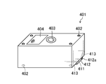
- Container 401 Bulk cargo picked up from the ship 301 by the pneumatic unloader 201 as described above may be stored in a silo or the like, or loaded in a truck, but it should be filled in a container 401 as shown in FIG. Can be handled in the same way as normal cargo containers.
- the upper portion of the outer shell of the container 401 has a size and shape conforming to, for example, the ISO standard, and engaging portions 402 that are engaged with a connecting tool called a twist lock or the like at four corners of the upper and lower surfaces. Is provided.
- the upper portion of the container 401 is also provided with an opening 403 through which bulk cargo flows in. This opening 403 can be connected to the discharge nozzle 224 of the pneumatic unloader 201 while maintaining a hermetic seal by flange connection or the like. However, depending on the type or the like of the bulk cargo, an open opening may be simply formed.
- a filter 404 is also provided on the upper surface of the container 401 so that when the bulk cargo is filled, the air in the container 401 is exhausted and the outflow of dust and the like can be suppressed.
- the bottom of the container 401 is provided with a discharge port 411 for discharging bulk cargo, and can be opened and closed by a discharge lid 412 that can rotate about a rotation shaft 412a.
- a discharge lid 412 that can rotate about a rotation shaft 412a.
- an inclined plate 413 is provided inside the container 401 from the peripheral edge of the discharge port 411 to the side wall so that the bulk cargo inside can be reliably discharged.
- a container 401 such as a grab bucket for handling bulk cargo, a cargo handling device such as a pneumatic unloader, a container yard without a storage facility such as a silo, etc. Since bulk cargo can be handled in the same way as ordinary cargo containers, it is possible to increase the flexibility of landing of bulk cargo and to make effective use of the quay.
- a baffle plate may be provided near the inside of the filter 404 in the container 401 so that the bulk cargo is less likely to come into direct contact with the filter 404 to make it easier to suppress the outflow of dust and the like. .
- the filter 404 is not limited to being provided at one place, but may be provided at a plurality of places.
- a baffle plate, a partition wall, etc. may be used as needed and provided in a side wall.
- a plurality of end portions in the longitudinal direction of the container 401 may be provided on the side wall, or one or more may be provided on each of the upper wall and the side wall.
- the single discharge lid 412 is not limited to being provided as described above, and may be provided so as to be divided into two or more and be double-opened. Further, a discharge lid may be provided so as to cover all or most of the bottom of the container 401 and to fully open or almost fully open the bottom. Moreover, you may enable it to open and close by providing a door in all or one part of the side wall of a longitudinal direction edge part, or the side wall along a longitudinal direction.
- an integral or separate lid or hatch for closing the opening 403 may be provided.
- an air conditioning unit capable of controlling at least one of temperature and humidity may be provided inside the container 401 as described above.
- an air conditioning unit capable of controlling at least one of temperature and humidity may be provided inside the container 401 as described above.
- the container 401 can be used as a transportation means for bulk cargo and used as a storage means at the transportation destination.
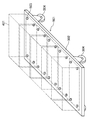
- the cart 501 includes a mounting table 502 on which a plurality of containers 401 as described above can be mounted, for example.
- a mounting table 502 on which a plurality of containers 401 as described above can be mounted, for example.
- an engaging portion 503 compliant with, for example, the ISO standard, which is the same as that used for fixing a container in a ship or a trailer.
- a member or the like for binding the container may be provided.
- the wheels 504 are attached to the lower part of the mounting table 502.
- the wheels 504 may be fixed in direction, or may be partially or entirely steerable (for example, 90 ° or more, 180 ° or more, or 360 ° rotation around the vertical axis).
- the moving direction can be changed without changing the direction of the carriage 504.
- a drive motor that drives some or all of the wheels such as the steerable wheels may be provided so that the cart 501 can run on its own.
- the cart 501 By using the cart 501 as described above, it is possible to handle a plurality of containers 401 in a lump, and thus it is possible to easily increase the operation rate of the container crane and the quay.
- a cart 501 By transporting such a cart 501 to another quay in combination with a dredge 601 as described below, such a cart 501 is landed from the dredger, and a container 401 placed on the cart 501 is trailered. Since it can be easily loaded without using a container crane installed in the container yard, the operation rate of the container crane and the quay can be further increased easily.
- the containers 401 may be stacked and placed on the cart 501 as described above.
- the cart 501 as described above is not limited to placing the container 401 filled with the bulk cargo, but may carry a normal cargo container.
- an arm that can be slid to the side and extended an arm that can be rotated about the vertical axis and extended to the side, and these arms are provided. It is also possible to provide auxiliary wheel equipment (trigger equipment) having the wheels arranged to increase the maximum distance (tread) between the left and right wheels as necessary.
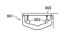
- a deck 602 is provided on the hull of a rod 601 suitable for loading and carrying the cart 501 as described above.
- the deck 602 is supported by a plurality of hydraulic cylinders 603 and can be controlled so that the height of the deck 602 matches the height of the quay. Thereby, the carriage 501 can be easily moved between the quay.
- a cart driving unit 611 that drives the movement (loading and / or landing) of the cart 501 with the quay.
- the driving method is not particularly limited.
- a connecting arm 612 attached to a chain driven by a motor can be connected to the carriage 501 and driven.
- the kite as described above may be a vehicle that can be self-propelled by being mounted with an engine or the like, or may be one that is towed by a towing boat.
- the cart 501 on which a plurality of containers are placed can be easily loaded and unloaded without using a container crane.
- Transport by container trailers can be easily performed in a distributed manner. Therefore, it is possible to ease the traffic congestion of the trailer in the container yard and increase the operation rate of the container crane and the quay.
- the deck 602 may further be provided with a rail or a guide for guiding the wheel 504 of the carriage 501. Further, a manual or automatic fixing mechanism or a stopper may be provided to fix the loaded carriage 501.
- a foldable transfer plate that extends between the deck 602 and the quay may be provided on the side of the deck 602.
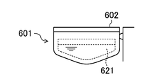
- ballast tank 621 is provided in the hull as shown in FIG. It may be. Further, the ballast tank 621 is divided into a port side and a starboard side, and the deck 602 is tilted together with the hull by left-right asymmetric pouring and the cart 501 can be moved between the quay by the inclination, or the like It is possible to facilitate the movement, or to reduce the driving load when using the cart 401 having the self-propelling capability as described above.
- a hydraulic cylinder 604 is provided in which the end of the cylinder body is pivotally supported by a rotation pin 605.
- the deck 602 may be tilted by operating these hydraulic cylinders 603 and 604 separately.
- the adjustment range of height and inclination can be increased, or the height of one of the hydraulic cylinder and ballast tank (mainly or exclusively) can be adjusted. May be adjusted.
- the height can be adjusted using a ballast tank at a deep water depth and using a hydraulic cylinder in a shallow water.
- a braking mechanism is provided on the rod 601 or the carriage 501 so that the speed and moving position of the carriage 501 can be controlled manually or automatically. It may be. More specifically, for example, the vehicle may be braked so as to suppress a speed exceeding a predetermined speed. Such braking may be performed electronically or mechanically using, for example, centrifugal force.
- the hydraulic cylinder 603 and the like may be automatically controlled so that the height difference between the deck 602 and the quay is detected and the height of the deck 602 is adjusted to the height of the quay.
- control it is possible to easily adjust the height and inclination of the deck 602 according to the movement of the center of gravity of the carriage 501. More specifically, for example, as the carriage 501 moves on the deck 602, the deck 602 may be kept horizontal or adjusted to have a predetermined inclination. Further, when the wheel of the carriage 501 rides over the deck 602 and the quay, the height and inclination of the deck 602 may be adjusted according to the magnitude and position of the load applied to the deck 602.
- the effect of facilitating the movement of the cargo between the quay by making the height of the deck 602 adjustable as described above is not limited to the cart 501, but also when transporting other carts and loads. Can get.
Landscapes
- Engineering & Computer Science (AREA)
- Mechanical Engineering (AREA)
- Ship Loading And Unloading (AREA)
Abstract
Selon l'invention, le taux d'exploitation d'une grue à conteneur et d'un mur de quai, est accru. Plus précisément, l'invention concerne un bogie pour conteneur de fret qui est équipé : d'un support de charge (502) sur lequel une pluralité de conteneurs de fret est chargée; de parties engagement (503) qui sont agencées côté face supérieure dudit support de charge, et qui permettent un engagement vis-à-vis des conteneurs de fret; et de roues (504) agencées côté face inférieure dudit support de charge.
Priority Applications (1)
| Application Number | Priority Date | Filing Date | Title |
|---|---|---|---|
| PCT/JP2015/001135 WO2016139699A1 (fr) | 2015-03-04 | 2015-03-04 | Bogie pour conteneur de fret |
Applications Claiming Priority (1)
| Application Number | Priority Date | Filing Date | Title |
|---|---|---|---|
| PCT/JP2015/001135 WO2016139699A1 (fr) | 2015-03-04 | 2015-03-04 | Bogie pour conteneur de fret |
Publications (1)
| Publication Number | Publication Date |
|---|---|
| WO2016139699A1 true WO2016139699A1 (fr) | 2016-09-09 |
Family
ID=56848053
Family Applications (1)
| Application Number | Title | Priority Date | Filing Date |
|---|---|---|---|
| PCT/JP2015/001135 Ceased WO2016139699A1 (fr) | 2015-03-04 | 2015-03-04 | Bogie pour conteneur de fret |
Country Status (1)
| Country | Link |
|---|---|
| WO (1) | WO2016139699A1 (fr) |
Citations (3)
| Publication number | Priority date | Publication date | Assignee | Title |
|---|---|---|---|---|
| JPH06298170A (ja) * | 1993-04-19 | 1994-10-25 | Ship & Ocean Zaidan | コンテナの水平荷役方式 |
| JP2001146296A (ja) * | 2000-05-29 | 2001-05-29 | Hiroshi Yamada | 搬送用コンテナ、搬送用荷台およびコンテナ装置 |
| JP2013095298A (ja) * | 2011-11-02 | 2013-05-20 | Nippon Trex Co Ltd | コンテナ積載用セミトレーラ |
-
2015
- 2015-03-04 WO PCT/JP2015/001135 patent/WO2016139699A1/fr not_active Ceased
Patent Citations (3)
| Publication number | Priority date | Publication date | Assignee | Title |
|---|---|---|---|---|
| JPH06298170A (ja) * | 1993-04-19 | 1994-10-25 | Ship & Ocean Zaidan | コンテナの水平荷役方式 |
| JP2001146296A (ja) * | 2000-05-29 | 2001-05-29 | Hiroshi Yamada | 搬送用コンテナ、搬送用荷台およびコンテナ装置 |
| JP2013095298A (ja) * | 2011-11-02 | 2013-05-20 | Nippon Trex Co Ltd | コンテナ積載用セミトレーラ |
Similar Documents
| Publication | Publication Date | Title |
|---|---|---|
| JP6216094B2 (ja) | 荷役方法 | |
| CN108602549B (zh) | 集装箱船 | |
| WO2016139698A1 (fr) | Conteneur de fret | |
| JP6126323B2 (ja) | 荷役装置 | |
| WO2021090428A1 (fr) | Procédé de chargement/déchargement de cargaison en vrac | |
| WO2016139699A1 (fr) | Bogie pour conteneur de fret | |
| WO2016139700A1 (fr) | Barge | |
| HK40074950A (en) | Handling method | |
| WO2021090429A1 (fr) | Dispositif de levage de conteneur de fret | |
| HK1240560A1 (zh) | 装卸方法 | |
| HK1240557A1 (en) | Cargo container | |
| HK1240561A1 (en) | Cargo handling device | |
| WO2018047214A1 (fr) | Procédé de chargement/déchargement de cargaison en vrac | |
| WO2018207230A1 (fr) | Navire |
Legal Events
| Date | Code | Title | Description |
|---|---|---|---|
| 121 | Ep: the epo has been informed by wipo that ep was designated in this application |
Ref document number: 15883869 Country of ref document: EP Kind code of ref document: A1 |
|
| NENP | Non-entry into the national phase |
Ref country code: DE |
|
| NENP | Non-entry into the national phase |
Ref country code: JP |
|
| 122 | Ep: pct application non-entry in european phase |
Ref document number: 15883869 Country of ref document: EP Kind code of ref document: A1 |