WO2016139775A1 - Buse d'usinage, tête d'usinage, équipement d'usinage, et procédé et programme de commande de buse d'usinage - Google Patents
Buse d'usinage, tête d'usinage, équipement d'usinage, et procédé et programme de commande de buse d'usinage Download PDFInfo
- Publication number
- WO2016139775A1 WO2016139775A1 PCT/JP2015/056349 JP2015056349W WO2016139775A1 WO 2016139775 A1 WO2016139775 A1 WO 2016139775A1 JP 2015056349 W JP2015056349 W JP 2015056349W WO 2016139775 A1 WO2016139775 A1 WO 2016139775A1
- Authority
- WO
- WIPO (PCT)
- Prior art keywords
- processing
- nozzle
- machining
- casing
- energy
- Prior art date
- Legal status (The legal status is an assumption and is not a legal conclusion. Google has not performed a legal analysis and makes no representation as to the accuracy of the status listed.)
- Ceased
Links
Images




Classifications
-
- B—PERFORMING OPERATIONS; TRANSPORTING
- B23—MACHINE TOOLS; METAL-WORKING NOT OTHERWISE PROVIDED FOR
- B23K—SOLDERING OR UNSOLDERING; WELDING; CLADDING OR PLATING BY SOLDERING OR WELDING; CUTTING BY APPLYING HEAT LOCALLY, e.g. FLAME CUTTING; WORKING BY LASER BEAM
- B23K26/00—Working by laser beam, e.g. welding, cutting or boring
- B23K26/14—Working by laser beam, e.g. welding, cutting or boring using a fluid stream, e.g. a jet of gas, in conjunction with the laser beam; Nozzles therefor
- B23K26/1462—Nozzles; Features related to nozzles
- B23K26/1464—Supply to, or discharge from, nozzles of media, e.g. gas, powder, wire
- B23K26/1476—Features inside the nozzle for feeding the fluid stream through the nozzle
-
- B—PERFORMING OPERATIONS; TRANSPORTING
- B23—MACHINE TOOLS; METAL-WORKING NOT OTHERWISE PROVIDED FOR
- B23K—SOLDERING OR UNSOLDERING; WELDING; CLADDING OR PLATING BY SOLDERING OR WELDING; CUTTING BY APPLYING HEAT LOCALLY, e.g. FLAME CUTTING; WORKING BY LASER BEAM
- B23K15/00—Electron-beam welding or cutting
- B23K15/0026—Auxiliary equipment
-
- B—PERFORMING OPERATIONS; TRANSPORTING
- B23—MACHINE TOOLS; METAL-WORKING NOT OTHERWISE PROVIDED FOR
- B23K—SOLDERING OR UNSOLDERING; WELDING; CLADDING OR PLATING BY SOLDERING OR WELDING; CUTTING BY APPLYING HEAT LOCALLY, e.g. FLAME CUTTING; WORKING BY LASER BEAM
- B23K15/00—Electron-beam welding or cutting
- B23K15/0046—Welding
- B23K15/0086—Welding welding for purposes other than joining, e.g. build-up welding
-
- B—PERFORMING OPERATIONS; TRANSPORTING
- B23—MACHINE TOOLS; METAL-WORKING NOT OTHERWISE PROVIDED FOR
- B23K—SOLDERING OR UNSOLDERING; WELDING; CLADDING OR PLATING BY SOLDERING OR WELDING; CUTTING BY APPLYING HEAT LOCALLY, e.g. FLAME CUTTING; WORKING BY LASER BEAM
- B23K26/00—Working by laser beam, e.g. welding, cutting or boring
- B23K26/14—Working by laser beam, e.g. welding, cutting or boring using a fluid stream, e.g. a jet of gas, in conjunction with the laser beam; Nozzles therefor
- B23K26/144—Working by laser beam, e.g. welding, cutting or boring using a fluid stream, e.g. a jet of gas, in conjunction with the laser beam; Nozzles therefor the fluid stream containing particles, e.g. powder
-
- B—PERFORMING OPERATIONS; TRANSPORTING
- B23—MACHINE TOOLS; METAL-WORKING NOT OTHERWISE PROVIDED FOR
- B23K—SOLDERING OR UNSOLDERING; WELDING; CLADDING OR PLATING BY SOLDERING OR WELDING; CUTTING BY APPLYING HEAT LOCALLY, e.g. FLAME CUTTING; WORKING BY LASER BEAM
- B23K26/00—Working by laser beam, e.g. welding, cutting or boring
- B23K26/34—Laser welding for purposes other than joining
-
- B—PERFORMING OPERATIONS; TRANSPORTING
- B23—MACHINE TOOLS; METAL-WORKING NOT OTHERWISE PROVIDED FOR
- B23K—SOLDERING OR UNSOLDERING; WELDING; CLADDING OR PLATING BY SOLDERING OR WELDING; CUTTING BY APPLYING HEAT LOCALLY, e.g. FLAME CUTTING; WORKING BY LASER BEAM
- B23K26/00—Working by laser beam, e.g. welding, cutting or boring
- B23K26/70—Auxiliary operations or equipment
Definitions
- the present invention relates to a machining nozzle, a machining head, a machining apparatus, a control method thereof, and a control program.
- Patent Document 1 discloses a nozzle that is a nozzle of a laser irradiation device and injects a material from a gap formed around the optical path of a laser beam in order to supply the material to a processing point. Yes.
- An object of the present invention is to provide a technique for solving the above-described problems.
- the processing nozzle comprises: A processing nozzle that performs processing by injecting a processing material toward a molten pool formed on a processing surface by energy rays, A cylindrical inner housing that includes a path through which the energy beam passes and emits the energy beam from one end; A cylindrical outer casing that encloses the inner casing and whose inner surface is narrowed in the emission direction of the energy rays emitted from the inner casing; A slide mechanism for changing a relative position of the outer casing with respect to the inner casing along the energy line; With The gap between the outer surface of the inner housing and the inner surface of the outer housing forms an injection port for the processed material, and the size of the injection port changes according to the change in the relative position by the slide mechanism. It is characterized by.
- a machining head comprises: The processing nozzle, and a focusing device for focusing energy beams; It is characterized by including.
- a processing apparatus comprises: The processing head, and a material supply unit for supplying a processing material to the processing head; A control unit that controls the slide mechanism and controls the spot diameter of the processed material; It is provided with.
- a processing nozzle control method includes: In order to process by injecting the processing material toward the molten pool formed on the processing surface by injecting energy rays, A cylindrical inner housing that includes a path through which the energy beam passes and emits the energy beam from one end; A cylindrical outer casing that encloses the inner casing and whose inner surface is narrowed in the emission direction of the energy rays emitted from the inner casing; A processing nozzle control method comprising: By changing the relative position of the outer casing with respect to the inner casing along the energy line, the irradiation of the processing material formed by the gap between the outer surface of the inner casing and the inner surface of the outer casing is performed. It is characterized by changing the size of the outlet.
- a processing nozzle control program includes: In order to process by injecting the processing material toward the molten pool formed on the processing surface by injecting energy rays, A cylindrical inner housing that includes a path through which the energy beam passes and emits the energy beam from one end; A cylindrical outer casing that encloses the inner casing and whose inner surface is narrowed in the emission direction of the energy rays emitted from the inner casing; A processing nozzle control program comprising: An input step for inputting modeling conditions; By changing the relative position of the outer casing with respect to the inner casing in accordance with the modeling conditions, the outer surface of the inner casing and the inner surface of the outer casing are changed. Changing the size of the injection port of the work material formed by the gap; Is executed by a computer.
- the utilization efficiency of the material can be improved without having to replace the nozzle.
- FIG. 1 is a schematic cross-sectional view of a processing nozzle 100 according to the present embodiment.
- the processing nozzle 100 is a nozzle for performing processing by injecting the processing material 130 toward the molten pool 121 formed on the processing surface 120 by the energy beam 110.
- the processing nozzle 100 includes an inner housing 101, an outer housing 102, and a slide mechanism 103.
- a source of the energy beam 110 a laser light source is used here, but an LED, a halogen lamp, or a xenon lamp can be used.
- the energy beam used for melting the material is not limited to the laser beam, and any energy beam can be used as long as it can melt the processed material on the processed surface.
- an energy beam such as an electron beam or an electromagnetic wave in a microwave to ultraviolet region may be used.
- the inner casing 101 has a cylindrical shape and is provided with a path through which the energy beam 110 passes, and the energy beam 110 is emitted from one end thereof.
- the outer surface of the inner casing 101 is narrowed in the emission direction of the energy beam 110 emitted from the inner casing 101. However, it is not necessarily limited.
- the outer casing 102 is also cylindrical and includes the inner casing 101, and the inner surface is narrowed in the emission direction of the energy beam 110 emitted from the inner casing 101. With such a structure, the processing material 130 can be injected toward the molten pool 121.
- the slide mechanism 103 changes the relative position of the outer casing 102 with respect to the inner casing 101 along the energy line 110.
- the gap between the outer surface of the inner housing 101 and the inner surface of the outer housing 102 forms the injection port 104 for the work material 130, and the size of the injection port 104 changes according to the change in the relative position by the slide mechanism 103. To do.
- downstream ends of the inner casing 101 and the outer casing 102 are both shown as conical cylinder shapes, but the present invention is not limited to this.
- both may have a polygonal pyramid shape.
- the inner casing 101 may be cylindrical and only the downstream end of the outer casing 102 may be conical.
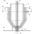
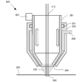
- FIG. 2 is a schematic cross-sectional view for explaining the internal configuration of the machining nozzle 200 according to the present embodiment.
- the processing nozzle 200 is a nozzle for injecting a powder 230 as a processing material toward a molten pool 260 formed on the processing surface 220 by a laser beam 210 as an energy ray.
- the processing nozzle 200 includes an inner casing 201, an outer casing 202, and a slide mechanism 203.
- the inner casing 201 has a cylindrical shape and has a path through which the laser beam 210 passes, and emits the laser beam 210 from one end thereof.
- the outer casing 202 is also cylindrical and includes the inner casing 201. Further, the inner casing 201 and the outer casing 202 each have a structure that is narrowed toward the optical axis of the laser beam 210.
- the processing nozzle 200 includes a powder supply unit 250 that supplies a carrier gas containing powder to the gap between the outer surface of the inner housing 201 and the inner surface of the outer housing 202.
- a seal member 221 such as an O-ring is provided between the outer surface of the inner housing 201 and the upper end of the inner surface of the outer housing 202 to prevent carrier gas from leaking.
- the outer surface at the downstream end of the inner casing 201 and the inner surface at the downstream end of the outer casing 202 have a cone shape, and the ring-shaped gap serves as the injection port 204.
- the outer casing 202 is slidable along the optical axis direction of the laser beam 210.
- the slide mechanism 203 changes the relative position of the outer casing 202 with respect to the inner casing 201 along the optical axis of the laser beam 210.
- the size of the injection port 204 changes according to the position change of the outer casing 202 by the slide mechanism 203.
- the slide mechanism 203 moves the outer casing 202 via a linear motor or a ball screw (not shown), but the present invention is not limited to this, and other mechanisms such as a rack and pinion are used. May be used.
- the powder supplied to the processing nozzle 200 is supplied from the powder supply unit 250 connected to the side surface of the outer casing 202 to the gap space between the inner casing 201 and the outer casing 202.
- the supplied powder material diffuses in the gap space and is injected from the ring-shaped injection port 204 toward the processing surface 220.
- the outer casing 202 is slid along the optical axis direction with respect to the inner casing 201, the relative positions of the lower ends of the inner casing 201 and the outer casing 202 shift, and the shape of the injection port 204 changes. By doing so, the injection state of the powder is changed.
- the slit width of the ring-shaped injection port 204 can be narrowed by sliding the outer casing 202 upward with respect to the inner casing 201, and the spot diameter of the material can be reduced. Can be small.
- the slit width of the ring-shaped injection port 204 can be widened, and the spot diameter can be increased to enter the bold writing mode. .
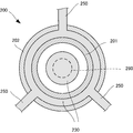
- FIG. 3 is a cross-sectional view taken along the line AA in FIG.
- the powder supply unit 250 is arranged so as to supply powder evenly from three locations to the outer casing 202. Thereby, isotropic powder is injected with respect to the molten pool 260, and a highly accurate process is realizable.
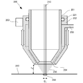
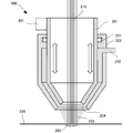
- FIG. 4 is a view showing a state in which the light beam of the laser beam 210 is narrowed and the outer casing 202 of FIG. 2 is slid upward in the drawing.
- the distance between the processing surface 220 and the lower end surface of the outer casing 202 increases from h 1 to h 2 , and the slit width of the injection port 204 increases. It can be seen that the powder spot diameter becomes narrower and smaller.
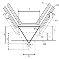
- FIG. 5A shows the state before and after the change.
- the nozzle height is changed from h 1 to h 2 in order to change the powder spot diameter accordingly. To change.
- the nozzle height calculation method will be described with reference to FIGS. 5A and 5B.
- casing may be sufficient.
- the inner casing 201 may be slid along the optical axis with respect to the outer casing 202 by fixing the outer casing 202 and rotating the inner casing 201.
- FIGS. 6 and 7 are schematic cross-sectional views for explaining the internal configuration of the machining nozzle 600 according to the present embodiment.
- the processing nozzle 600 according to the present embodiment is different from the second embodiment in that it has a slide mechanism 601 for sliding the inner housing 201. Since other configurations and operations are the same as those of the second embodiment, the same configurations and operations are denoted by the same reference numerals, and detailed description thereof is omitted.
- the inner casing 201 is slid downward.
- the injection spot 204 can be narrowed to make the powder spot smaller in accordance with the diameter of the molten pool 260.
- both the inner casing and the outer casing may be moved upward without changing the powder spot diameter.
- D 1 molten pool diameter
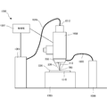
- the optical processing apparatus 1000 includes any one of the processing nozzles 100, 200, and 600 described in the above-described embodiments, and melts a material with heat generated by condensed light, thereby forming a three-dimensional structure (or overlaying). This is a device for generating welding.
- an optical processing apparatus 1000 including the processing nozzle 200 will be described.
- the optical processing apparatus 1000 includes a light source 1001, an optical transmission unit 1015, a stage 1005, a material storage device 1006, a material supply unit 1030, a processing head 1008, and a control unit 1007.
- a laser light source is used as the light source 1001, but an LED, a halogen lamp, or a xenon lamp can be used.
- the energy beam used for melting the material is not limited to the laser beam, and any energy beam may be used as long as the powder material can be melted at the processing point.
- an energy beam such as an electron beam or an electromagnetic wave in a microwave to ultraviolet region may be used.
- the light transmission unit 1015 is an optical fiber having a core diameter of ⁇ 0.01 to 1 mm, for example, and guides light generated by the light source 1001 to the processing head 1008.
- the material container 1006 supplies a carrier gas containing a material to the processing head 1008 via the material supply unit 1030.
- the material is particles such as metal particles and resin particles.
- the carrier gas is an inert gas, and may be, for example, argon gas, nitrogen gas, or helium gas.
- the material supply unit 1030 is, for example, a resin or metal hose, and guides the powder flow in which the material is mixed into the carrier gas to the processing head 1008. However, when the material is a wire, no carrier gas is required.
- the processing head 1008 includes a focusing device that focuses light as an energy ray, and a processing nozzle 200 is attached downstream of the focusing device.
- the laser light supplied to the processing head 1008 is adjusted so as to be condensed on the processing surface 220 through an optical system including a lens or the like provided therein, and passes through the processing nozzle 200 to be processed. Is irradiated.
- the optical system is provided so as to be able to control the condensing position by controlling the lens interval and the like.
- the control unit 1007 inputs modeling conditions such as fine writing or thick writing, changes the output value of the laser light from the light source 1001 according to the input modeling conditions, and slides the outer casing 202 of the processing nozzle 200. . Thereby, the powder spot diameter by the powder injected from the processing nozzle 200 is controlled in accordance with the molten pool diameter.
- the modeled object 1010 is created on the stage 1005.
- Light emitted from the processing head 1008 is collected on the processing surface 220 on the modeled object 1010.
- the processing surface 220 is heated and condensed by light collection to form a molten pool in part.
- Material is injected from the processing nozzle 200 into the molten pool 260 on the processing surface 220. Then, the material melts into the molten pool 260. Thereafter, the molten pool 260 is cooled and solidified, so that the material is deposited on the processing surface 220 and three-dimensional modeling is realized.
- a program installed in the computer a medium storing the program, and a WWW (World Wide Web) server that downloads the program are also included in the scope of the present invention.
- a non-transitory computer readable medium storing a program for causing a computer to execute the processing steps included in the above-described embodiments is included in the scope of the present invention.
Landscapes
- Engineering & Computer Science (AREA)
- Physics & Mathematics (AREA)
- Optics & Photonics (AREA)
- Mechanical Engineering (AREA)
- Plasma & Fusion (AREA)
- Laser Beam Processing (AREA)
- Welding Or Cutting Using Electron Beams (AREA)
Abstract
Priority Applications (4)
| Application Number | Priority Date | Filing Date | Title |
|---|---|---|---|
| JP2016510537A JP6234551B2 (ja) | 2015-03-04 | 2015-03-04 | 加工ノズル、加工ヘッド、加工装置、その制御方法および制御プログラム |
| EP15785039.7A EP3085518A4 (fr) | 2015-03-04 | 2015-03-04 | Buse d'usinage, tête d'usinage, équipement d'usinage, et procédé et programme de commande de buse d'usinage |
| PCT/JP2015/056349 WO2016139775A1 (fr) | 2015-03-04 | 2015-03-04 | Buse d'usinage, tête d'usinage, équipement d'usinage, et procédé et programme de commande de buse d'usinage |
| US14/888,236 US10537966B2 (en) | 2015-03-04 | 2015-03-04 | Processing nozzle, processing head, machining apparatus, and control method and control program of processing nozzle |
Applications Claiming Priority (1)
| Application Number | Priority Date | Filing Date | Title |
|---|---|---|---|
| PCT/JP2015/056349 WO2016139775A1 (fr) | 2015-03-04 | 2015-03-04 | Buse d'usinage, tête d'usinage, équipement d'usinage, et procédé et programme de commande de buse d'usinage |
Publications (1)
| Publication Number | Publication Date |
|---|---|
| WO2016139775A1 true WO2016139775A1 (fr) | 2016-09-09 |
Family
ID=56848789
Family Applications (1)
| Application Number | Title | Priority Date | Filing Date |
|---|---|---|---|
| PCT/JP2015/056349 Ceased WO2016139775A1 (fr) | 2015-03-04 | 2015-03-04 | Buse d'usinage, tête d'usinage, équipement d'usinage, et procédé et programme de commande de buse d'usinage |
Country Status (4)
| Country | Link |
|---|---|
| US (1) | US10537966B2 (fr) |
| EP (1) | EP3085518A4 (fr) |
| JP (1) | JP6234551B2 (fr) |
| WO (1) | WO2016139775A1 (fr) |
Cited By (2)
| Publication number | Priority date | Publication date | Assignee | Title |
|---|---|---|---|---|
| JP2019059114A (ja) * | 2017-09-26 | 2019-04-18 | 技術研究組合次世代3D積層造形技術総合開発機構 | ノズル及び積層造形装置 |
| JP2019166818A (ja) * | 2018-03-26 | 2019-10-03 | 技術研究組合次世代3D積層造形技術総合開発機構 | ノズルおよび積層造形装置 |
Families Citing this family (11)
| Publication number | Priority date | Publication date | Assignee | Title |
|---|---|---|---|---|
| EP3095592A4 (fr) * | 2015-03-20 | 2017-11-01 | Technology Research Association For Future Additive Manufacturing | Buse de travail, tête de travail, dispositif de travail, procédé de commande de buse de travail et programme de commande |
| US10307803B2 (en) * | 2016-07-20 | 2019-06-04 | The United States Of America As Represented By Secretary Of The Navy | Transmission window cleanliness for directed energy devices |
| EP3442773B1 (fr) * | 2016-07-29 | 2023-10-18 | Hewlett-Packard Development Company, L.P. | Fusion par laser de matériaux de construction |
| US10029476B2 (en) * | 2016-09-30 | 2018-07-24 | Hamilton Sundstrand Corporation | Laser enhancements of micro cold spray printed powder |
| CN106738887B (zh) * | 2017-02-13 | 2023-02-03 | 张晓军 | 3d打印设备和丝 |
| US10457035B2 (en) | 2017-03-07 | 2019-10-29 | General Electric Company | Apparatuses and systems for net shape manufacturing |
| CN107214958B (zh) * | 2017-07-27 | 2018-06-26 | 苏艳敏 | 一种双口径3d打印机喷头 |
| US11433488B2 (en) * | 2018-03-15 | 2022-09-06 | Gkn Aerospace St. Louis Llc | Gas dispersion for additive manufacturing |
| WO2021123921A1 (fr) * | 2019-12-20 | 2021-06-24 | Beam | Ensemble buse de dépôt d'énergie dirigée avec buse et vibrateur qui fait vibrer la buse, et appareil de dépôt d'énergie dirigée comportant un tel ensemble buse |
| JP7639823B2 (ja) | 2020-07-22 | 2025-03-05 | 株式会社ニコン | 加工システム |
| JP2024077972A (ja) * | 2022-11-29 | 2024-06-10 | 住友重機械ハイマテックス株式会社 | ガスシールド方法及び二重ガスノズル並びに外付けノズル外筒 |
Citations (6)
| Publication number | Priority date | Publication date | Assignee | Title |
|---|---|---|---|---|
| US5418350A (en) | 1992-01-07 | 1995-05-23 | Electricite De Strasbourg (S.A.) | Coaxial nozzle for surface treatment by laser irradiation, with supply of materials in powder form |
| JPH10501463A (ja) * | 1994-01-27 | 1998-02-10 | クロマロイ ガス タービン コーポレイション | レーザーによる粉末金属クラッディングノズル |
| JPH11333584A (ja) * | 1998-05-26 | 1999-12-07 | Mitsubishi Heavy Ind Ltd | レーザ加工ヘッド |
| JP2002519200A (ja) * | 1998-06-30 | 2002-07-02 | ジオティー マズムダー | レーザクラッディング装置及び方法 |
| JP2006068819A (ja) * | 2004-08-31 | 2006-03-16 | Winkler & Duennebier Ag | 裁断ローラまたは型押しローラをレーザ肉盛溶接によって製作するための方法および装置 |
| JP2007222869A (ja) * | 2006-02-22 | 2007-09-06 | General Electric Co <Ge> | レーザネットシェイプ製造法のためのノズル |
Family Cites Families (4)
| Publication number | Priority date | Publication date | Assignee | Title |
|---|---|---|---|---|
| US5486676A (en) * | 1994-11-14 | 1996-01-23 | General Electric Company | Coaxial single point powder feed nozzle |
| EP1928631A4 (fr) | 2005-08-23 | 2009-08-05 | Hardwear Pty Ltd | Buse de distribution de poudre |
| JP5292256B2 (ja) | 2009-10-20 | 2013-09-18 | 株式会社日立製作所 | レーザ加工ヘッド、及びレーザ肉盛方法 |
| JP5616769B2 (ja) * | 2010-12-13 | 2014-10-29 | 株式会社日立製作所 | レーザ加工ヘッド及び肉盛溶接方法 |
-
2015
- 2015-03-04 WO PCT/JP2015/056349 patent/WO2016139775A1/fr not_active Ceased
- 2015-03-04 US US14/888,236 patent/US10537966B2/en active Active
- 2015-03-04 EP EP15785039.7A patent/EP3085518A4/fr not_active Withdrawn
- 2015-03-04 JP JP2016510537A patent/JP6234551B2/ja active Active
Patent Citations (6)
| Publication number | Priority date | Publication date | Assignee | Title |
|---|---|---|---|---|
| US5418350A (en) | 1992-01-07 | 1995-05-23 | Electricite De Strasbourg (S.A.) | Coaxial nozzle for surface treatment by laser irradiation, with supply of materials in powder form |
| JPH10501463A (ja) * | 1994-01-27 | 1998-02-10 | クロマロイ ガス タービン コーポレイション | レーザーによる粉末金属クラッディングノズル |
| JPH11333584A (ja) * | 1998-05-26 | 1999-12-07 | Mitsubishi Heavy Ind Ltd | レーザ加工ヘッド |
| JP2002519200A (ja) * | 1998-06-30 | 2002-07-02 | ジオティー マズムダー | レーザクラッディング装置及び方法 |
| JP2006068819A (ja) * | 2004-08-31 | 2006-03-16 | Winkler & Duennebier Ag | 裁断ローラまたは型押しローラをレーザ肉盛溶接によって製作するための方法および装置 |
| JP2007222869A (ja) * | 2006-02-22 | 2007-09-06 | General Electric Co <Ge> | レーザネットシェイプ製造法のためのノズル |
Non-Patent Citations (1)
| Title |
|---|
| See also references of EP3085518A4 |
Cited By (4)
| Publication number | Priority date | Publication date | Assignee | Title |
|---|---|---|---|---|
| JP2019059114A (ja) * | 2017-09-26 | 2019-04-18 | 技術研究組合次世代3D積層造形技術総合開発機構 | ノズル及び積層造形装置 |
| US11534968B2 (en) | 2017-09-26 | 2022-12-27 | Technology Research Association For Future Additive Manufacturing | Nozzle and additive manufacturing apparatus |
| JP2019166818A (ja) * | 2018-03-26 | 2019-10-03 | 技術研究組合次世代3D積層造形技術総合開発機構 | ノズルおよび積層造形装置 |
| JP7063670B2 (ja) | 2018-03-26 | 2022-05-09 | 技術研究組合次世代3D積層造形技術総合開発機構 | ノズルおよび積層造形装置 |
Also Published As
| Publication number | Publication date |
|---|---|
| US20160375521A1 (en) | 2016-12-29 |
| US10537966B2 (en) | 2020-01-21 |
| EP3085518A4 (fr) | 2017-03-01 |
| JPWO2016139775A1 (ja) | 2017-04-27 |
| JP6234551B2 (ja) | 2017-11-22 |
| EP3085518A1 (fr) | 2016-10-26 |
Similar Documents
| Publication | Publication Date | Title |
|---|---|---|
| JP6234551B2 (ja) | 加工ノズル、加工ヘッド、加工装置、その制御方法および制御プログラム | |
| JP5997850B1 (ja) | 加工ノズル、加工ヘッド、加工装置、加工ノズルの制御方法および制御プログラム | |
| JP6289565B2 (ja) | 加工ノズル、加工ヘッド、加工装置、加工方法および加工プログラム | |
| JP6092467B2 (ja) | 加工ノズル、加工ヘッド、加工装置 | |
| RU2641578C2 (ru) | Головка для нанесения при производстве по аддитивной технологии | |
| US12059748B2 (en) | Additive manufacturing system and method of forming an object in a powder bed | |
| CN109475980A (zh) | 激光焊接、包覆和/或增材制造系统以及激光焊接、包覆和/或增材制造的方法 | |
| CN105817621A (zh) | 用于加工材料的方法 | |
| CN104325220B (zh) | 一种多功能激光复合加工设备及方法 | |
| JP6134861B2 (ja) | 光加工ヘッド、光加工装置および光加工方法 | |
| CN109641319A (zh) | 一种控制激光束在工作平面中的横向功率分布来激光加工金属材料的方法,以及用于实施所述方法的机器和计算机程序 | |
| JP6749308B2 (ja) | レーザ積層造形装置及びレーザ積層方法 | |
| US20180166251A1 (en) | Three-dimensional layer-by-layer shaping apparatus, three-dimensional layer-by-layer shaping apparatus control method, and three-dimensional layer-by-layer shaping apparatus control program | |
| CN106975750A (zh) | 一种激光熔融沉积成型装置及其运行方法 | |
| JP2019059114A (ja) | ノズル及び積層造形装置 | |
| CN105772724B (zh) | 一种提高激光金属3d成形件质量的方法 | |
| CN104651833B (zh) | 激光光内送粉熔覆凹凸缺陷的修复方法及修复装置 | |
| KR20180093350A (ko) | 가변형 레이저 클래딩 헤드 | |
| CN204570041U (zh) | 一种光纤激光同轴送粉嘴 | |
| CN206689426U (zh) | 一种激光熔融沉积成型装置 | |
| CN106825571B (zh) | 一种用于3d打印金属工件的同轴送粉装置 | |
| CN204277214U (zh) | 一种多功能激光复合加工设备 | |
| JP6951337B2 (ja) | 直接材料堆積用レーザ走査ヘッドを備えるノズル | |
| JP2019037997A (ja) | レーザクラッディング装置 | |
| CN111201099B (zh) | 制造三维工件的设备和方法 |
Legal Events
| Date | Code | Title | Description |
|---|---|---|---|
| WWE | Wipo information: entry into national phase |
Ref document number: 14888236 Country of ref document: US |
|
| REEP | Request for entry into the european phase |
Ref document number: 2015785039 Country of ref document: EP |
|
| WWE | Wipo information: entry into national phase |
Ref document number: 2015785039 Country of ref document: EP |
|
| ENP | Entry into the national phase |
Ref document number: 2016510537 Country of ref document: JP Kind code of ref document: A |
|
| 121 | Ep: the epo has been informed by wipo that ep was designated in this application |
Ref document number: 15785039 Country of ref document: EP Kind code of ref document: A1 |
|
| NENP | Non-entry into the national phase |
Ref country code: DE |