WO2016139799A1 - Turbocompresseur - Google Patents
Turbocompresseur Download PDFInfo
- Publication number
- WO2016139799A1 WO2016139799A1 PCT/JP2015/056518 JP2015056518W WO2016139799A1 WO 2016139799 A1 WO2016139799 A1 WO 2016139799A1 JP 2015056518 W JP2015056518 W JP 2015056518W WO 2016139799 A1 WO2016139799 A1 WO 2016139799A1
- Authority
- WO
- WIPO (PCT)
- Prior art keywords
- housing
- turbine
- mount
- shroud
- turbine wheel
- Prior art date
- Legal status (The legal status is an assumption and is not a legal conclusion. Google has not performed a legal analysis and makes no representation as to the accuracy of the status listed.)
- Ceased
Links
Images


Classifications
-
- F—MECHANICAL ENGINEERING; LIGHTING; HEATING; WEAPONS; BLASTING
- F01—MACHINES OR ENGINES IN GENERAL; ENGINE PLANTS IN GENERAL; STEAM ENGINES
- F01D—NON-POSITIVE DISPLACEMENT MACHINES OR ENGINES, e.g. STEAM TURBINES
- F01D25/00—Component parts, details, or accessories, not provided for in, or of interest apart from, other groups
- F01D25/24—Casings; Casing parts, e.g. diaphragms, casing fastenings
- F01D25/26—Double casings; Measures against temperature strain in casings
-
- F—MECHANICAL ENGINEERING; LIGHTING; HEATING; WEAPONS; BLASTING
- F01—MACHINES OR ENGINES IN GENERAL; ENGINE PLANTS IN GENERAL; STEAM ENGINES
- F01D—NON-POSITIVE DISPLACEMENT MACHINES OR ENGINES, e.g. STEAM TURBINES
- F01D11/00—Preventing or minimising internal leakage of working-fluid, e.g. between stages
- F01D11/003—Preventing or minimising internal leakage of working-fluid, e.g. between stages by packing rings; Mechanical seals
-
- F—MECHANICAL ENGINEERING; LIGHTING; HEATING; WEAPONS; BLASTING
- F01—MACHINES OR ENGINES IN GENERAL; ENGINE PLANTS IN GENERAL; STEAM ENGINES
- F01D—NON-POSITIVE DISPLACEMENT MACHINES OR ENGINES, e.g. STEAM TURBINES
- F01D11/00—Preventing or minimising internal leakage of working-fluid, e.g. between stages
- F01D11/005—Sealing means between non relatively rotating elements
-
- F—MECHANICAL ENGINEERING; LIGHTING; HEATING; WEAPONS; BLASTING
- F01—MACHINES OR ENGINES IN GENERAL; ENGINE PLANTS IN GENERAL; STEAM ENGINES
- F01D—NON-POSITIVE DISPLACEMENT MACHINES OR ENGINES, e.g. STEAM TURBINES
- F01D25/00—Component parts, details, or accessories, not provided for in, or of interest apart from, other groups
- F01D25/28—Supporting or mounting arrangements, e.g. for turbine casing
-
- F—MECHANICAL ENGINEERING; LIGHTING; HEATING; WEAPONS; BLASTING
- F01—MACHINES OR ENGINES IN GENERAL; ENGINE PLANTS IN GENERAL; STEAM ENGINES
- F01D—NON-POSITIVE DISPLACEMENT MACHINES OR ENGINES, e.g. STEAM TURBINES
- F01D5/00—Blades; Blade-carrying members; Heating, heat-insulating, cooling or antivibration means on the blades or the members
- F01D5/02—Blade-carrying members, e.g. rotors
- F01D5/04—Blade-carrying members, e.g. rotors for radial-flow machines or engines
- F01D5/043—Blade-carrying members, e.g. rotors for radial-flow machines or engines of the axial inlet- radial outlet, or vice versa, type
-
- F—MECHANICAL ENGINEERING; LIGHTING; HEATING; WEAPONS; BLASTING
- F01—MACHINES OR ENGINES IN GENERAL; ENGINE PLANTS IN GENERAL; STEAM ENGINES
- F01D—NON-POSITIVE DISPLACEMENT MACHINES OR ENGINES, e.g. STEAM TURBINES
- F01D9/00—Stators
- F01D9/02—Nozzles; Nozzle boxes; Stator blades; Guide conduits, e.g. individual nozzles
- F01D9/026—Scrolls for radial machines or engines
-
- F—MECHANICAL ENGINEERING; LIGHTING; HEATING; WEAPONS; BLASTING
- F02—COMBUSTION ENGINES; HOT-GAS OR COMBUSTION-PRODUCT ENGINE PLANTS
- F02B—INTERNAL-COMBUSTION PISTON ENGINES; COMBUSTION ENGINES IN GENERAL
- F02B39/00—Component parts, details, or accessories relating to, driven charging or scavenging pumps, not provided for in groups F02B33/00 - F02B37/00
-
- F—MECHANICAL ENGINEERING; LIGHTING; HEATING; WEAPONS; BLASTING
- F02—COMBUSTION ENGINES; HOT-GAS OR COMBUSTION-PRODUCT ENGINE PLANTS
- F02B—INTERNAL-COMBUSTION PISTON ENGINES; COMBUSTION ENGINES IN GENERAL
- F02B39/00—Component parts, details, or accessories relating to, driven charging or scavenging pumps, not provided for in groups F02B33/00 - F02B37/00
- F02B39/14—Lubrication of pumps; Safety measures therefor
-
- F—MECHANICAL ENGINEERING; LIGHTING; HEATING; WEAPONS; BLASTING
- F02—COMBUSTION ENGINES; HOT-GAS OR COMBUSTION-PRODUCT ENGINE PLANTS
- F02B—INTERNAL-COMBUSTION PISTON ENGINES; COMBUSTION ENGINES IN GENERAL
- F02B37/00—Engines characterised by provision of pumps driven at least for part of the time by exhaust
-
- F—MECHANICAL ENGINEERING; LIGHTING; HEATING; WEAPONS; BLASTING
- F05—INDEXING SCHEMES RELATING TO ENGINES OR PUMPS IN VARIOUS SUBCLASSES OF CLASSES F01-F04
- F05D—INDEXING SCHEME FOR ASPECTS RELATING TO NON-POSITIVE-DISPLACEMENT MACHINES OR ENGINES, GAS-TURBINES OR JET-PROPULSION PLANTS
- F05D2220/00—Application
- F05D2220/40—Application in turbochargers
-
- F—MECHANICAL ENGINEERING; LIGHTING; HEATING; WEAPONS; BLASTING
- F05—INDEXING SCHEMES RELATING TO ENGINES OR PUMPS IN VARIOUS SUBCLASSES OF CLASSES F01-F04
- F05D—INDEXING SCHEME FOR ASPECTS RELATING TO NON-POSITIVE-DISPLACEMENT MACHINES OR ENGINES, GAS-TURBINES OR JET-PROPULSION PLANTS
- F05D2230/00—Manufacture
- F05D2230/50—Building or constructing in particular ways
- F05D2230/54—Building or constructing in particular ways by sheet metal manufacturing
-
- F—MECHANICAL ENGINEERING; LIGHTING; HEATING; WEAPONS; BLASTING
- F05—INDEXING SCHEMES RELATING TO ENGINES OR PUMPS IN VARIOUS SUBCLASSES OF CLASSES F01-F04
- F05D—INDEXING SCHEME FOR ASPECTS RELATING TO NON-POSITIVE-DISPLACEMENT MACHINES OR ENGINES, GAS-TURBINES OR JET-PROPULSION PLANTS
- F05D2240/00—Components
- F05D2240/55—Seals
- F05D2240/58—Piston ring seals
- F05D2240/581—Double or plural piston ring arrangements, i.e. two or more piston rings
Definitions
- the present disclosure relates to a turbocharger.
- a turbocharger is known as a means for increasing the thermal efficiency of an internal combustion engine.
- the center core disposed at the center of the scroll portion of the turbocharger is formed integrally with the flow passage outlet portion, the bearing fitting portion, and the column from the steel pipe material, and the thermal deformation of the scroll portion body is It is disclosed that the turbocharger aims to prevent the change of the tip clearance due to the cost reduction and to reduce the cost and the weight, and to improve the durability and the reliability and the impact resistance of the turbine.
- Patent Document 1 by adopting a center core formed by integrally forming steel materials annularly in a turbocharger, the thickness can be reduced and the heat capacity is reduced, so that the temperature rise of the turbine part becomes fast, and the exhaust gas on the downstream side The warm air of the purification device is promoted, and the purification action of the exhaust gas purification device is efficiently exhibited.
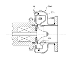
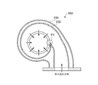
- a scroll channel 014 is formed in the first housing 030.
- a temperature distribution as shown in FIG. 8 occurs in the first housing 030.
- the first housing 030 tends to have a relatively low temperature on the bearing housing 006 side, and bending deformation in the direction of arrow A shown in FIGS. 7 and 8 due to this temperature distribution Occurs in the first housing 030.
- the present invention has been made in view of the above-described conventional problems, and an object of the present invention is to make it possible to achieve high turbine efficiency while avoiding contact between a turbine wheel and a shroud. It is to provide a charger.
- a turbocharger includes a turbine wheel configured to be rotated by exhaust gas of an engine, and a scroll flow that accommodates the turbine wheel and through which exhaust gas supplied to the turbine wheel flows
- a turbine housing which forms at least a part of a passage, and a bearing that rotatably supports the shaft of the turbine wheel, and a bearing housing connected to the turbine housing, and an opposing surface facing the tip of the blade of the turbine wheel
- a shroud having a face and configured to surround the turbine wheel, wherein the shroud is provided inside the turbine housing with a clearance from the turbine housing, and an axial direction of the turbine wheel Than the scroll channel Serial comprises a mount which is supported on at least one of said turbine housing and said bearing housing in the bearing housing side, and a connecting portion which connects the said mounting shroud.
- the shroud is a separate component from the turbine housing
- the tip clearance between the shroud and the turbine wheel is basically not affected by the above-mentioned bending deformation of the turbine housing. Therefore, even if the tip clearance between the shroud and the turbine wheel is reduced, the contact between the shroud and the turbine wheel due to the bending deformation of the turbine housing can be avoided. Therefore, high turbine efficiency can be realized while avoiding contact between the turbine wheel and the shroud.
- each of the connection portions has a wing shape in a cross-sectional shape perpendicular to an axis of the turbine wheel.
- connection section in which the cross-sectional shape perpendicular to the axis of the turbine wheel has a blade shape flows between the shroud and the mount Since the exhaust gas is rectified, higher turbine efficiency can be realized.
- the turbocharger according to (1) or (2) further includes a seal ring that seals the gap between the shroud and the turbine housing.
- the mount is sandwiched between the turbine housing and the bearing housing.
- the turbo described in the above (1) to (3) with a simple configuration by holding the mount between the turbine housing and the bearing housing which the turbocharger inherently has A charger can be realized.
- the mount is an annular flat plate, and an outer peripheral portion of the mount is sandwiched between the turbine housing and the bearing housing. ing.
- one side of the annular flat plate can be secured while securing the rigidity of the connection portion and the mount for supporting the shroud. It can be used to form part of the scroll channel.
- the thickness direction of the annular flat plate matches the axial direction of the turbine wheel, the shaft of the turbine wheel Since the amount of thermal expansion of the directional mount can be reduced, it is possible to suppress the variation in tip clearance between the turbine wheel and the shroud.
- the turbocharger further comprises a bolt for fastening the turbine housing and the bearing housing, and an outer peripheral portion of the mount has an axial force of the bolt Between the turbine housing and the bearing housing.
- the mount since the mount is attached to the turbine housing and the bearing housing by fastening the turbine housing and the bearing housing with the bolt, by appropriately setting the fastening force of the bolt,
- the mount can be fixed to the turbine housing and the bearing housing with a simple configuration.
- the mount in the turbocharger according to (4), includes a cylindrical portion extending in an axial direction of the turbine wheel, and the cylindrical portion to the cylindrical portion. And a protruding portion that protrudes to the outer peripheral side, and the protruding portion of the mount is sandwiched between the turbine housing and the bearing housing.
- the mount can be held between the turbine housing and the bearing housing at a position corresponding to the axial length of the cylindrical portion.
- a clamping member coupled by clamping a flange provided on the turbine housing and a flange provided on the bearing housing is further provided.
- the protrusion of the mount is held between the turbine housing and the bearing housing by a holding force of the holding member.
- the mount since the mount is attached to the turbine housing and the bearing housing by holding the turbine housing and the bearing housing by the holding member, the holding force of the holding member is appropriately set.
- the mount can be fixed to the turbine housing and the bearing housing with a simple configuration.
- the mount is an annular member, and an annular step portion formed on the bearing housing The fitting portion is fitted in the inlay.
- the axial center of the shroud supported by the mount via the connection portion can be made to coincide with the axial center of the shaft supported by the bearing with a simple configuration.
- a sheet metal housing the turbine wheel and forming at least a part of the scroll flow path The turbine housing includes a first housing, and the shroud is provided inside the first housing with the gap with respect to the first housing.
- the turbine housing includes a first housing made of sheet metal that houses the turbine wheel and forms at least a portion of the scroll flow path, compared to when the entire turbine housing including the first housing is made of castings,
- first housing large bending deformation (thermal deformation) is likely to occur under the influence of the exhaust gas flowing through the scroll passage.
- the shroud by providing the shroud with a gap from the first housing made of sheet metal and providing the inside of the first housing, the effect of such bending deformation can be shrouded. Will not receive it basically.
- the turbine housing is a two-layered housing further having a second housing made of sheet metal that accommodates the first housing.
- the turbine housing is a two-layer structure housing, even if the turbine wheel is broken for some reason and fragments are scattered, compared to the single-layer structure.
- the scattering of debris to the outside of the turbine housing 4 can be more reliably prevented.
- an outlet guide cylinder integrally formed with the second housing so as to guide the exhaust gas that has passed through the turbine wheel; And a piston ring sealing a gap between the first housing and the outlet guide cylinder such that the first housing can slide in the axial direction of the turbine wheel with respect to the outlet guide cylinder.
- the first housing forming at least a part of the scroll flow path is the first one.
- the first housing and the outlet guide are configured such that the first housing can slide in the axial direction with respect to the outlet guide cylinder integrally formed with the second housing. It has a piston ring that seals the gap between the cylinders.
- the turbine housing is a one-layer housing, and a thickness of the shroud is larger than a thickness of the first housing.
- the thickness of the first housing may be a shroud by making the thickness of the shroud thicker than the thickness of the first housing.
- the thickness of the shroud is equal to or greater than twice the thickness of the first housing.
- a turbocharger is provided that enables high turbine efficiency to be achieved while avoiding contact between the turbine wheel and the shroud.
- FIG. 5 is a view showing an example of the cross-sectional shape perpendicular to the axis O1 of the turbine wheel 2 in the connection portion 12 shown in FIGS. 1 to 4;
- FIG. 5 is a view showing an example of the cross-sectional shape perpendicular to the axis O1 of the turbine wheel 2 in the connection portion 12 shown in FIGS. 1 to 4; It is a figure which shows typically the cross-sectional structure of the turbocharger which concerns on one reference form. It is a figure which shows the temperature distribution of the inner casing 030 at the time of driving
- expressions that indicate that things such as “identical”, “equal” and “homogeneous” are equal states not only represent strictly equal states, but also have tolerances or differences with which the same function can be obtained. It also represents the existing state.
- expressions representing shapes such as quadrilateral shapes and cylindrical shapes not only represent shapes such as rectangular shapes and cylindrical shapes in a geometrically strict sense, but also uneven portions and chamfers within the range where the same effect can be obtained. The shape including a part etc. shall also be expressed.
- the expressions “comprising”, “having”, “having”, “including” or “having” one component are not exclusive expressions excluding the presence of other components.
- FIG. 1 is a view schematically showing a cross-sectional configuration of a turbocharger 100A according to an embodiment.
- FIG. 2 is a view schematically showing a cross-sectional configuration of a turbocharger 100B according to an embodiment.
- FIG. 3 is a view schematically showing a cross-sectional configuration of a turbocharger 100C according to an embodiment.
- FIG. 4 is a view schematically showing a cross-sectional configuration of a turbocharger 100D according to an embodiment.
- the turbocharger 100 (100A-100D) includes a turbine wheel 2, a turbine housing 4, a bearing housing 6, a shroud 8, a mount 10 and at least one connection.
- a unit 12 is provided.
- the turbine wheel 2 is configured to be rotated by the exhaust gas of an engine (not shown).
- the turbine housing 4 accommodates the turbine wheel 2 and forms at least a part of a scroll passage 14 through which exhaust gas supplied to the turbine wheel 2 flows.
- the bearing housing 6 accommodates a bearing 18 rotatably supporting the shaft 16 of the turbine wheel 2 and is connected to the turbine housing 4.
- the shroud 8 has an opposing surface 8 a that faces the tip 20 a of the blade 20 of the turbine wheel 2 and is configured to surround the turbine wheel 2. Further, the shroud 8 is configured as a component separate from the turbine housing 4 and is provided inside the turbine housing 4 with a gap 22 with respect to the turbine housing 4.
- the mount 10 is supported by at least one of the turbine housing 4 and the bearing housing 6 on the side closer to the bearing housing 6 than the scroll passage 14 in the axial direction of the turbine wheel 2.
- Each of the at least one connection 12 (the plurality of connections 12 in the embodiment shown in FIGS. 1 to 4) is configured to connect the mount 10 and the shroud 8.
- the turbocharger 100 (100A to 100D) even if the exhaust gas flowing through the scroll passage 14 causes a temperature distribution in the turbine housing 4 and the turbine housing 4 is bent (thermally deformed), the shroud 8 Is formed separately from the turbine housing 4 and provided with a gap 22 with respect to the turbine housing 4, the tip clearance between the shroud 8 and the turbine wheel 2 (the facing surface 8 a and the tip 20 a And the clearance) is basically not affected by the bending deformation of the turbine housing 4. Therefore, even if the tip clearance between the shroud 8 and the turbine wheel 2 is reduced, the contact between the shroud 8 and the turbine wheel 2 due to the above-described bending deformation of the turbine housing 4 can be avoided. Therefore, high turbine efficiency can be realized while avoiding contact between the turbine wheel 2 and the shroud 8.
- the turbine housing 4 includes a first sheet metal housing 30 that receives the turbine wheel 2 and forms at least a portion of the scroll channel 14;
- the shroud 8 is provided inside the first housing 30 with a gap 22 with respect to the first housing 30.
- the first housing 30 is made of a sheet metal, so the exhaust gas flowing in the scroll flow path 14 causes an influence. Large bending deformation (thermal deformation) is likely to occur in the first housing 30.
- the shroud 8 is provided on the inner side of the first housing 30 with a gap 22 with respect to the first housing 30 made of sheet metal, so as described above, the turbine wheel 2 and the shroud 8 High turbine efficiency can be achieved while avoiding contact with the
- the turbine housing 4 is a two-layered housing further having a sheet metal second housing 32 for housing the first housing 30.
- the turbine housing is a two-layered housing, even if the turbine wheel 2 is broken for some reason and fragments are scattered, the turbine housing 4 is moved out as compared with the single-layered structure. Fragments can be prevented more reliably.
- the turbocharger 100 (100A, 100B) further comprises an outlet guide cylinder 34 and a piston ring 36.
- the outlet guide cylinder 34 is configured to guide the exhaust gas that has passed through the turbine wheel 2 and is joined to the outlet flange 35 of the tar casing 4.
- the outlet flange 35 is joined to the second housing 32 by welding, for example, and the second housing 32 and the outlet guide cylinder 34 are integrally configured together with the outlet flange 35.
- the piston ring 36 is configured to seal the gap 38 between the first housing 30 and the outlet guide cylinder 34 so that the first housing 30 can slide in the axial direction of the turbine wheel 2 with respect to the outlet guide cylinder 34 There is.
- the turbine housing 4 is a two-layered housing including the first housing 30 and the second housing 32 as shown in FIGS. 1 and 2, the first housing forming at least a part of the scroll channel 14 At 30, the temperature rises relatively more than the second housing 32, and the thermal expansion amount becomes larger. For this reason, if nothing is devised, stress may concentrate on the connection portion between the first housing 30 and the second housing 32 and damage may occur.
- the turbocharger 100 100A, 100B shown in FIG. 1 and FIG. 2
- the first housing 30 has an axis with respect to the outlet guide cylinder 34 configured integrally with the second housing 32.
- a piston ring 36 is provided to seal the gap 38 between the first housing 30 and the outlet guide cylinder 34 so as to be slidable in the direction. Thereby, while suppressing the leak of the exhaust gas from the gap 38 between the first housing 30 and the outlet guide cylinder 34, the damage due to the difference in the amount of thermal expansion between the first housing 30 and the second housing 32 is avoided. be able to.
- the turbine housing 4 is a one-layer housing, and the thickness of the shroud 8 is larger than the thickness of the first housing 30.
- the thickness of the shroud 8 is made larger than the thickness of the first housing 30 so that the thickness of the first housing 30 is increased. As compared with the case where the thickness is larger than the thickness, when the turbine wheel 2 is broken, fragments of the turbine wheel 2 can be effectively received with less material.
- the thickness of the shroud 8 is preferably twice or more the thickness of the first housing 30.
- the turbine housing 4 comprises an annular structure 33 in a portion adjacent to the bearing housing 6, and the mount 10 is a part of the turbine housing 4. It is held between the structural portion 33 and the bearing housing 6.
- the structural portion 33 is, for example, a cast, and the first housing 30 made of sheet metal and the second housing 32 made of sheet metal. May be joined by welding or the like.
- the annular structural portion 33 may be, for example, a casting, and may be joined to the first housing 30 by welding or the like.
- the mount 10 is held by the turbine housing 4 and the bearing housing 6 inherently provided in the turbocharger, so that the mounting is performed with a simple configuration. 10 can be fixed.
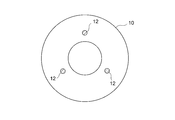
- the mount 10 is an annular flat plate, and the outer peripheral portion 10a of the mount 10 is a turbine housing 4 and a bearing housing It is held by six.
- the rigidity of the mount 10 for supporting the shroud 8 through the connection portion 12 is secured, and the scroll flow is performed using the single face 10 f of the mount 10 Part of the channel 14 can be formed. Further, even in the case of forming a part of the scroll flow passage 14 by using the single face 10 f of the mount 10, if the thickness direction of the mount 10 matches the axial direction of the turbine wheel 2, the turbine wheel 2 Since the thermal expansion of the mount 10 in the axial direction can be reduced, it is possible to suppress the variation of the tip clearance between the turbine wheel 2 and the shroud 8.
- the turbocharger 100 (100A, 100C) further comprises a bolt 26 for fastening the structural portion 33 of the turbine housing 4 and the bearing housing 6 .
- the outer peripheral portion 10 a of the mount 10 is held between the structural portion 33 of the turbine housing 4 and the bearing housing 6 by the axial force of the bolt 26.
- the mount 10 is attached to the turbine housing 4 and the bearing housing 6 by fastening the turbine housing 4 and the bearing housing 6 with the bolt 26, the fastening force of the bolt 26 can be set appropriately to simplify the operation.
- the mount 10 can be fixed to the turbine housing 4 and the bearing housing 6 in a configuration.
- the mount 10 includes the cylindrical portion 10 b extending in the axial direction of the turbine wheel 2 and the outer peripheral side of the cylindrical portion 10 b from the cylindrical portion 10 b And an annular protrusion 10c protruding to the In this case, the protrusion 10 c of the mount 10 is sandwiched between the turbine housing 4 and the bearing housing 6.
- the mount 10 can be held between the turbine housing 4 and the bearing housing 6 at a position corresponding to the axial length of the cylindrical portion 10 b.
- the turbocharger 100 (100 B, 100 D) may be provided with a flange 40 provided on the structural portion 33 of the turbine housing 4 and a flange provided on the bearing housing 6.
- a clamping member 28 is further provided, which is coupled by clamping 42 and 42.
- the protruding portion 10 c of the mount 10 is held between the structural portion 33 of the turbine housing 4 and the bearing housing 6 by the holding force of the holding member 28.
- the holding member 28 may be, for example, a C ring having a C-shaped cross section.
- the mount 10 is attached to the turbine housing 4 and the bearing housing 6 by connecting the flange of the turbine housing 4 and the flange of the bearing housing 6 by the holding member 28, the holding force of the holding member 28 is appropriately set.
- the mount 10 can be fixed to the turbine housing 4 and the bearing housing 6 with a simple configuration.
- the mount 10 is an annular member, and the fitting portion 10 d is inlaid with the annular step portion 6 a formed in the bearing housing 6.
- the axial center O2 of the shroud 8 supported by the mount 10 via the connection portion 12 and the axial center O1 of the shaft 16 supported by the bearing 18 can be matched with a simple configuration.
- the turbocharger 100 (100A-100D) further comprises a backplate.
- the back plate 23 seals the exhaust gas that leaks from the inlet of the turbine wheel 5 and flows to the back side of the turbine wheel 5, and is provided to thermally isolate the heat so as not to transfer to the bearing side.
- the outer peripheral end of the back plate 23 is supported by an annular step 10 e provided on the inner peripheral surface of the mount 10, and the inner peripheral end of the back plate is supported by an annular step 6 b of the bearing housing 6. It is done.
- the annular step portion 6 b is provided on the inner peripheral side of the annular step portion 6 a.
- the turbocharger 100 (100A-100D) further comprises a seal ring 24 that seals the gap 22 between the shroud 8 and the first housing 30.
- the seal ring 24 desirably has elasticity enough to maintain the seal of the gap between the shroud 8 and the first housing 30 even if the first housing 30 is thermally deformed, for example, as shown in FIGS. 1 to 4.
- One having a C-shaped cross section may be used, an O-ring may be used, or another shape may be used.
- FIG. 5 is a view showing an example of a cross-sectional shape perpendicular to the axis O1 of the turbine wheel 2 in the connection portion 12 shown in FIGS.
- FIG. 6 is a view showing another example of the cross-sectional shape perpendicular to the axis O1 of the turbine wheel 2 in the connection portion 12 shown in FIGS.
- each of the connections 12 is wing-shaped in cross-section perpendicular to the axis of the turbine wheel 2.
- the wing-shaped leading edge upstream side of the exhaust gas flow
- the exhaust gas flow has a trailing edge (the exhaust gas flow) along the flow direction of the exhaust gas flowing through the scroll flow path 14 and flowing into the turbine wheel 2. It is configured to be located radially outward of the downstream side of the gas flow).
- each of the connections 12 is circular in cross-sectional shape perpendicular to the axis of the turbine wheel 2.
- shroud 8 and mount 10 can be connected by simple composition.
- the present invention is not limited to the above-described embodiments, and includes the embodiments in which the above-described embodiments are modified or the embodiments in which these embodiments are appropriately combined.
Landscapes
- Engineering & Computer Science (AREA)
- Mechanical Engineering (AREA)
- General Engineering & Computer Science (AREA)
- Chemical & Material Sciences (AREA)
- Combustion & Propulsion (AREA)
- Supercharger (AREA)
Abstract
Priority Applications (5)
| Application Number | Priority Date | Filing Date | Title |
|---|---|---|---|
| EP15883966.2A EP3267010B1 (fr) | 2015-03-05 | 2015-03-05 | Turbocompresseur |
| JP2017503291A JP6580122B2 (ja) | 2015-03-05 | 2015-03-05 | ターボチャージャ |
| PCT/JP2015/056518 WO2016139799A1 (fr) | 2015-03-05 | 2015-03-05 | Turbocompresseur |
| CN201580077408.1A CN107407198B (zh) | 2015-03-05 | 2015-03-05 | 涡轮增压器 |
| US15/555,251 US10801368B2 (en) | 2015-03-05 | 2015-03-05 | Turbocharger |
Applications Claiming Priority (1)
| Application Number | Priority Date | Filing Date | Title |
|---|---|---|---|
| PCT/JP2015/056518 WO2016139799A1 (fr) | 2015-03-05 | 2015-03-05 | Turbocompresseur |
Publications (1)
| Publication Number | Publication Date |
|---|---|
| WO2016139799A1 true WO2016139799A1 (fr) | 2016-09-09 |
Family
ID=56849263
Family Applications (1)
| Application Number | Title | Priority Date | Filing Date |
|---|---|---|---|
| PCT/JP2015/056518 Ceased WO2016139799A1 (fr) | 2015-03-05 | 2015-03-05 | Turbocompresseur |
Country Status (5)
| Country | Link |
|---|---|
| US (1) | US10801368B2 (fr) |
| EP (1) | EP3267010B1 (fr) |
| JP (1) | JP6580122B2 (fr) |
| CN (1) | CN107407198B (fr) |
| WO (1) | WO2016139799A1 (fr) |
Cited By (13)
| Publication number | Priority date | Publication date | Assignee | Title |
|---|---|---|---|---|
| JP2018109403A (ja) * | 2016-12-21 | 2018-07-12 | マン・ディーゼル・アンド・ターボ・エスイー | ターボチャージャ |
| EP3354856A1 (fr) * | 2017-01-30 | 2018-08-01 | Honeywell International Inc. | Carter de turbine en tôle à noyau coulé |
| WO2018179328A1 (fr) * | 2017-03-31 | 2018-10-04 | 三菱重工エンジン&ターボチャージャ株式会社 | Logement de turbine et turbocompresseur équipé de celui-ci |
| WO2018207754A1 (fr) * | 2017-05-10 | 2018-11-15 | カルソニックカンセイ株式会社 | Carter de turbine |
| WO2019044777A1 (fr) * | 2017-08-28 | 2019-03-07 | 株式会社豊田自動織機 | Turbocompresseur |
| WO2019044775A1 (fr) * | 2017-08-28 | 2019-03-07 | 株式会社豊田自動織機 | Turbocompresseur |
| WO2019064388A1 (fr) * | 2017-09-27 | 2019-04-04 | 三菱重工エンジン&ターボチャージャ株式会社 | Logement de turbine et compresseur de suralimentation équipé de celui-ci |
| CN110023589A (zh) * | 2016-12-01 | 2019-07-16 | 曼恩能源方案有限公司 | 涡轮增压器 |
| US10436069B2 (en) | 2017-01-30 | 2019-10-08 | Garrett Transportation I Inc. | Sheet metal turbine housing with biaxial volute configuration |
| US10472988B2 (en) | 2017-01-30 | 2019-11-12 | Garrett Transportation I Inc. | Sheet metal turbine housing and related turbocharger systems |
| US10494955B2 (en) | 2017-01-30 | 2019-12-03 | Garrett Transportation I Inc. | Sheet metal turbine housing with containment dampers |
| JPWO2021245860A1 (fr) * | 2020-06-04 | 2021-12-09 | ||
| US11732729B2 (en) | 2021-01-26 | 2023-08-22 | Garrett Transportation I Inc | Sheet metal turbine housing |
Families Citing this family (9)
| Publication number | Priority date | Publication date | Assignee | Title |
|---|---|---|---|---|
| KR101805683B1 (ko) * | 2016-07-08 | 2017-12-08 | 진석 | 플라즈마 및 근적외선을 이용한 피부 미용 장치 |
| EP3734039A4 (fr) * | 2017-12-26 | 2021-09-08 | Marelli Corporation | Procédé de fabrication d'enveloppe de turbine |
| DE102018107304A1 (de) * | 2018-03-27 | 2019-10-02 | Man Energy Solutions Se | Turbolader |
| JP6639728B1 (ja) * | 2018-11-29 | 2020-02-05 | トヨタ自動車株式会社 | ターボチャージャ |
| JP7424752B2 (ja) * | 2019-03-25 | 2024-01-30 | 株式会社豊田自動織機 | ターボチャージャ |
| JP7099625B2 (ja) * | 2019-04-17 | 2022-07-12 | 株式会社Ihi | タービンハウジングおよび過給機 |
| EP3789638A1 (fr) * | 2019-09-05 | 2021-03-10 | Siemens Aktiengesellschaft | Joint pour appareil de combustion |
| WO2023228467A1 (fr) * | 2022-05-25 | 2023-11-30 | 株式会社Ihi | Turbine et compresseur de suralimentation |
| JPWO2024237107A1 (fr) * | 2023-05-12 | 2024-11-21 |
Citations (5)
| Publication number | Priority date | Publication date | Assignee | Title |
|---|---|---|---|---|
| JPS63150424A (ja) * | 1986-12-15 | 1988-06-23 | Honda Motor Co Ltd | タ−ボチヤ−ジヤのハウジング構造 |
| JP2007002791A (ja) * | 2005-06-24 | 2007-01-11 | Toyota Motor Corp | タービンハウジング |
| JP2007309139A (ja) * | 2006-05-16 | 2007-11-29 | Toyota Motor Corp | ターボチャージャ |
| JP2010096110A (ja) * | 2008-10-17 | 2010-04-30 | Ihi Corp | ターボチャージャ |
| JP2013068153A (ja) * | 2011-09-22 | 2013-04-18 | Mitsubishi Heavy Ind Ltd | ターボチャージャのシールリング組付け方法及びターボチャージャ |
Family Cites Families (20)
| Publication number | Priority date | Publication date | Assignee | Title |
|---|---|---|---|---|
| US4907952A (en) | 1986-12-05 | 1990-03-13 | Honda Giken Kogyo Kabushiki Kaisha | Turbocharger |
| EP0571205B1 (fr) * | 1992-05-21 | 1997-03-05 | Alliedsignal Limited | Turbosoufflante réglable |
| DE4238550A1 (de) * | 1992-11-14 | 1994-05-19 | Daimler Benz Ag | Abgasturbolader für eine Brennkraftmaschine |
| DE19615237C2 (de) * | 1996-04-18 | 1999-10-28 | Daimler Chrysler Ag | Abgasturbolader für eine Brennkraftmaschine |
| JP3597758B2 (ja) | 2000-04-19 | 2004-12-08 | アイシン高丘株式会社 | 過給機のタービンハウジング |
| DE10212675B4 (de) * | 2002-03-22 | 2006-05-18 | Daimlerchrysler Ag | Abgasturbolader in einer Brennkraftmaschine |
| EP1543220B1 (fr) * | 2002-09-05 | 2008-05-21 | Honeywell International Inc. | Turbocompresseur comprenant un dispositif de tuyere variable |
| DE10325649B4 (de) * | 2003-06-06 | 2014-10-23 | Ihi Charging Systems International Gmbh | Abgasturbine für einen Abgasturbolader |
| DE10352960B4 (de) | 2003-11-13 | 2006-06-14 | Benteler Automobiltechnik Gmbh | Gehäuseanordnung für den Turbolader einer Brennkraftmaschine |
| US6982216B1 (en) * | 2004-10-27 | 2006-01-03 | Sony Corporation | MOSFET having reduced parasitic resistance and method of forming same |
| DE102006018055A1 (de) * | 2006-04-19 | 2007-10-31 | Daimlerchrysler Ag | Abgasturbolader für eine Brennkraftmaschine |
| KR101021658B1 (ko) | 2008-08-12 | 2011-03-17 | (주)계양정밀 | 가변노즐장치를 구비한 터보차져 |
| US8545172B2 (en) * | 2009-06-15 | 2013-10-01 | Honeywell International, Inc. | Turbocharger having nozzle ring locating pin and an integrated locator and heat shield |
| DE102009042260B4 (de) * | 2009-09-22 | 2015-12-10 | Benteler Automobiltechnik Gmbh | Abgasturbolader |
| JP5769407B2 (ja) | 2010-02-01 | 2015-08-26 | 三菱重工業株式会社 | 板金タービンハウジング |
| JP5832090B2 (ja) * | 2010-12-15 | 2015-12-16 | 三菱重工業株式会社 | ターボチャージャハウジングのシール構造 |
| WO2012147161A1 (fr) * | 2011-04-26 | 2012-11-01 | トヨタ自動車株式会社 | Carcasse de turbine destinée à un turbocompresseur |
| JP5299574B2 (ja) | 2011-07-06 | 2013-09-25 | トヨタ自動車株式会社 | タービンハウジング及び排気タービン過給機 |
| JP5983239B2 (ja) * | 2012-09-25 | 2016-08-31 | 株式会社Ihi | 過給機 |
| JP2015031237A (ja) | 2013-08-06 | 2015-02-16 | 株式会社Ihi | 可変ノズルユニット及び可変容量型過給機 |
-
2015
- 2015-03-05 CN CN201580077408.1A patent/CN107407198B/zh not_active Expired - Fee Related
- 2015-03-05 EP EP15883966.2A patent/EP3267010B1/fr active Active
- 2015-03-05 JP JP2017503291A patent/JP6580122B2/ja not_active Expired - Fee Related
- 2015-03-05 US US15/555,251 patent/US10801368B2/en not_active Expired - Fee Related
- 2015-03-05 WO PCT/JP2015/056518 patent/WO2016139799A1/fr not_active Ceased
Patent Citations (5)
| Publication number | Priority date | Publication date | Assignee | Title |
|---|---|---|---|---|
| JPS63150424A (ja) * | 1986-12-15 | 1988-06-23 | Honda Motor Co Ltd | タ−ボチヤ−ジヤのハウジング構造 |
| JP2007002791A (ja) * | 2005-06-24 | 2007-01-11 | Toyota Motor Corp | タービンハウジング |
| JP2007309139A (ja) * | 2006-05-16 | 2007-11-29 | Toyota Motor Corp | ターボチャージャ |
| JP2010096110A (ja) * | 2008-10-17 | 2010-04-30 | Ihi Corp | ターボチャージャ |
| JP2013068153A (ja) * | 2011-09-22 | 2013-04-18 | Mitsubishi Heavy Ind Ltd | ターボチャージャのシールリング組付け方法及びターボチャージャ |
Cited By (35)
| Publication number | Priority date | Publication date | Assignee | Title |
|---|---|---|---|---|
| CN110023589A (zh) * | 2016-12-01 | 2019-07-16 | 曼恩能源方案有限公司 | 涡轮增压器 |
| JP2018109403A (ja) * | 2016-12-21 | 2018-07-12 | マン・ディーゼル・アンド・ターボ・エスイー | ターボチャージャ |
| US10436069B2 (en) | 2017-01-30 | 2019-10-08 | Garrett Transportation I Inc. | Sheet metal turbine housing with biaxial volute configuration |
| EP3354856A1 (fr) * | 2017-01-30 | 2018-08-01 | Honeywell International Inc. | Carter de turbine en tôle à noyau coulé |
| CN108374698A (zh) * | 2017-01-30 | 2018-08-07 | 霍尼韦尔国际公司 | 具有铸造芯部的金属板涡轮机外壳 |
| US10494955B2 (en) | 2017-01-30 | 2019-12-03 | Garrett Transportation I Inc. | Sheet metal turbine housing with containment dampers |
| US10472988B2 (en) | 2017-01-30 | 2019-11-12 | Garrett Transportation I Inc. | Sheet metal turbine housing and related turbocharger systems |
| US11035254B2 (en) | 2017-01-30 | 2021-06-15 | Garrett Transportation I Inc | Sheet metal turbine housing with cast core |
| US10544703B2 (en) | 2017-01-30 | 2020-01-28 | Garrett Transportation I Inc. | Sheet metal turbine housing with cast core |
| WO2018179328A1 (fr) * | 2017-03-31 | 2018-10-04 | 三菱重工エンジン&ターボチャージャ株式会社 | Logement de turbine et turbocompresseur équipé de celui-ci |
| CN110139974A (zh) * | 2017-03-31 | 2019-08-16 | 三菱重工发动机和增压器株式会社 | 涡轮壳体及具备该涡轮壳体的涡轮增压器 |
| JPWO2018179328A1 (ja) * | 2017-03-31 | 2019-11-07 | 三菱重工エンジン&ターボチャージャ株式会社 | タービンハウジングおよびそれを備えたターボチャージャ |
| CN110139974B (zh) * | 2017-03-31 | 2021-08-06 | 三菱重工发动机和增压器株式会社 | 涡轮壳体及具备该涡轮壳体的涡轮增压器 |
| US11506086B2 (en) | 2017-03-31 | 2022-11-22 | Mitsubishi Heavy Industries Engine & Turbocharger, Ltd. | Turbine housing and turbo charger provided with same |
| EP3543500A4 (fr) * | 2017-03-31 | 2019-12-11 | Mitsubishi Heavy Industries Engine & Turbocharger, Ltd. | Logement de turbine et turbocompresseur équipé de celui-ci |
| CN110678635A (zh) * | 2017-05-10 | 2020-01-10 | 马瑞利株式会社 | 涡轮机壳体 |
| CN110678635B (zh) * | 2017-05-10 | 2021-07-16 | 马瑞利株式会社 | 涡轮机壳体 |
| WO2018207754A1 (fr) * | 2017-05-10 | 2018-11-15 | カルソニックカンセイ株式会社 | Carter de turbine |
| EP3623598B1 (fr) * | 2017-05-10 | 2022-08-03 | Marelli Corporation | Carter de turbine |
| US11015612B2 (en) | 2017-05-10 | 2021-05-25 | Marelli Corporation | Turbine housing |
| JPWO2018207754A1 (ja) * | 2017-05-10 | 2020-05-14 | マレリ株式会社 | タービンハウジング |
| CN111065803B (zh) * | 2017-08-28 | 2021-10-19 | 株式会社丰田自动织机 | 涡轮增压器 |
| CN111065803A (zh) * | 2017-08-28 | 2020-04-24 | 株式会社丰田自动织机 | 涡轮增压器 |
| WO2019044775A1 (fr) * | 2017-08-28 | 2019-03-07 | 株式会社豊田自動織機 | Turbocompresseur |
| JPWO2019044777A1 (ja) * | 2017-08-28 | 2020-09-03 | 株式会社豊田自動織機 | ターボチャージャ |
| WO2019044777A1 (fr) * | 2017-08-28 | 2019-03-07 | 株式会社豊田自動織機 | Turbocompresseur |
| CN110573711B (zh) * | 2017-09-27 | 2022-04-05 | 三菱重工发动机和增压器株式会社 | 涡轮壳体以及具有该涡轮壳体的增压器 |
| US11221022B2 (en) | 2017-09-27 | 2022-01-11 | Mitsubishi Heavy Industries Engine & Turbocharger, Ltd. | Turbine housing and turbocharger including the same |
| CN110573711A (zh) * | 2017-09-27 | 2019-12-13 | 三菱重工发动机和增压器株式会社 | 涡轮壳体以及具有该涡轮壳体的增压器 |
| JPWO2019064388A1 (ja) * | 2017-09-27 | 2020-04-09 | 三菱重工エンジン&ターボチャージャ株式会社 | タービンハウジング及びこれを備えた過給機 |
| WO2019064388A1 (fr) * | 2017-09-27 | 2019-04-04 | 三菱重工エンジン&ターボチャージャ株式会社 | Logement de turbine et compresseur de suralimentation équipé de celui-ci |
| JPWO2021245860A1 (fr) * | 2020-06-04 | 2021-12-09 | ||
| WO2021245860A1 (fr) * | 2020-06-04 | 2021-12-09 | 三菱重工マリンマシナリ株式会社 | Carter de turbine et turbine de suralimentation |
| JP7286017B2 (ja) | 2020-06-04 | 2023-06-02 | 三菱重工マリンマシナリ株式会社 | タービンハウジングおよび過給機 |
| US11732729B2 (en) | 2021-01-26 | 2023-08-22 | Garrett Transportation I Inc | Sheet metal turbine housing |
Also Published As
| Publication number | Publication date |
|---|---|
| JPWO2016139799A1 (ja) | 2017-11-16 |
| EP3267010A1 (fr) | 2018-01-10 |
| US20180016942A1 (en) | 2018-01-18 |
| JP6580122B2 (ja) | 2019-09-25 |
| EP3267010B1 (fr) | 2019-05-08 |
| CN107407198A (zh) | 2017-11-28 |
| CN107407198B (zh) | 2020-07-28 |
| EP3267010A4 (fr) | 2018-03-21 |
| US10801368B2 (en) | 2020-10-13 |
Similar Documents
| Publication | Publication Date | Title |
|---|---|---|
| WO2016139799A1 (fr) | Turbocompresseur | |
| JP6351049B2 (ja) | タービンハウジングおよびタービンハウジングの製造方法 | |
| CN107208546B (zh) | 可变容量型增压器 | |
| CN105793537B (zh) | 涡轮壳体 | |
| JP6542246B2 (ja) | 可変容量型過給機 | |
| JP6331423B2 (ja) | 可変容量型過給機 | |
| JP2013174129A (ja) | ターボチャージャ | |
| CN102762838A (zh) | 可变容量式涡轮增压器 | |
| US10385765B2 (en) | Variable geometry turbocharger | |
| JP2016108956A (ja) | コンプレッサ、これを備えた過給機、ならびにコンプレッサのスロート通路幅調整方法 | |
| WO2016051531A1 (fr) | Turbine | |
| WO2017109995A1 (fr) | Mécanisme à buse variable et turbocompresseur à géométrie variable | |
| JP7107433B2 (ja) | 可変容量型過給機 | |
| US10233828B2 (en) | Variable nozzle unit and variable geometry system turbocharger | |
| JP5854819B2 (ja) | ターボチャージャーの締結部構造 | |
| WO2019087279A1 (fr) | Turbine et turbocompresseur la comprenant | |
| JP6756008B2 (ja) | ターボチャージャ | |
| JP2013155669A (ja) | ターボ過給機 | |
| WO2016136313A1 (fr) | Turbocompresseur de suralimentation et procédé de fabrication associé | |
| JP2015224570A (ja) | ターボチャージャ | |
| WO2022264313A1 (fr) | Structure de montage de roue de compresseur et compresseur de suralimentation |
Legal Events
| Date | Code | Title | Description |
|---|---|---|---|
| 121 | Ep: the epo has been informed by wipo that ep was designated in this application |
Ref document number: 15883966 Country of ref document: EP Kind code of ref document: A1 |
|
| ENP | Entry into the national phase |
Ref document number: 2017503291 Country of ref document: JP Kind code of ref document: A |
|
| WWE | Wipo information: entry into national phase |
Ref document number: 15555251 Country of ref document: US |
|
| REEP | Request for entry into the european phase |
Ref document number: 2015883966 Country of ref document: EP |
|
| NENP | Non-entry into the national phase |
Ref country code: DE |