WO2016140108A1 - Dispositif de refroidissement et réfrigérateur - Google Patents
Dispositif de refroidissement et réfrigérateur Download PDFInfo
- Publication number
- WO2016140108A1 WO2016140108A1 PCT/JP2016/055284 JP2016055284W WO2016140108A1 WO 2016140108 A1 WO2016140108 A1 WO 2016140108A1 JP 2016055284 W JP2016055284 W JP 2016055284W WO 2016140108 A1 WO2016140108 A1 WO 2016140108A1
- Authority
- WO
- WIPO (PCT)
- Prior art keywords
- cooling
- members
- cooling device
- cooling members
- refrigerator
- Prior art date
- Legal status (The legal status is an assumption and is not a legal conclusion. Google has not performed a legal analysis and makes no representation as to the accuracy of the status listed.)
- Ceased
Links
Images





Classifications
-
- F—MECHANICAL ENGINEERING; LIGHTING; HEATING; WEAPONS; BLASTING
- F25—REFRIGERATION OR COOLING; COMBINED HEATING AND REFRIGERATION SYSTEMS; HEAT PUMP SYSTEMS; MANUFACTURE OR STORAGE OF ICE; LIQUEFACTION SOLIDIFICATION OF GASES
- F25D—REFRIGERATORS; COLD ROOMS; ICE-BOXES; COOLING OR FREEZING APPARATUS NOT OTHERWISE PROVIDED FOR
- F25D3/00—Devices using other cold materials; Devices using cold-storage bodies
-
- F—MECHANICAL ENGINEERING; LIGHTING; HEATING; WEAPONS; BLASTING
- F25—REFRIGERATION OR COOLING; COMBINED HEATING AND REFRIGERATION SYSTEMS; HEAT PUMP SYSTEMS; MANUFACTURE OR STORAGE OF ICE; LIQUEFACTION SOLIDIFICATION OF GASES
- F25D—REFRIGERATORS; COLD ROOMS; ICE-BOXES; COOLING OR FREEZING APPARATUS NOT OTHERWISE PROVIDED FOR
- F25D25/00—Charging, supporting, and discharging the articles to be cooled
Definitions
- the present invention relates to an apparatus for cooling a container containing a beverage or the like.
- Patent Document 1 discloses a cooling device, a cooling system, and a cooling heating system.
- the cooling system includes a pair of cooling devices.
- Each cooling device includes a plate-shaped electronic cooling element (Peltier element), a water cooling jacket connected to one surface side of the electronic cooling element, a heat transfer member connected to the other surface side of the electronic cooling element, It is comprised from the frame member which fixes an electronic cooling element and a heat transfer member integrally, and the heat insulation member connected to the curved part of a heat transfer member, and formed from foaming urethane etc.
- Peltier element plate-shaped electronic cooling element
- Water cooling jacket connected to one surface side of the electronic cooling element
- a heat transfer member connected to the other surface side of the electronic cooling element
- Japanese Patent Laid-Open No. 2012-233651 discloses a refrigerator.
- the cooler includes a cooling chamber for storing a container containing a liquid beverage, a cooling means for cooling air in the cooling chamber, and a cooling chamber.
- Japanese Unexamined Patent Application Publication No. 2014-37908 discloses a cooling structure of a cooling tank and a manufacturing method thereof.
- the cooling tank body is a bottomed cylindrical cooling tank body made of a metal material having an opening at the top and a discharge plate communicating with the inside of the bottom plate.
- a cooling structure that is fitted to the cooling area of the outer wall of the cooling tank and that is provided with cooling means for cooling the fluid in the cooling tank to a predetermined temperature.
- the cooling means watertightly fits a cylindrical jacket made of at least the same metal material as the cooling tank main body, and is joined along the longitudinal direction from one outer wall surface of the upper or lower part of the cylindrical jacket.
- a spiral refrigerant passage having a predetermined cross-sectional shape is integrally formed between the outer wall surface of the cooling tank and the cylindrical jacket at a predetermined pitch while being joined together.
- An object of the present invention is to provide a cooling device that is easier to use than the prior art and a refrigerator equipped with the cooling device.
- a plurality of cooling members for surrounding the periphery of the cooling object and at least one for adjusting a gap between the plurality of cooling members according to the size of the cooling object.
- An apparatus for cooling comprising an adjustment member is provided.
- the at least one adjustment member includes at least one elastic member for biasing the plurality of cooling members in a direction of narrowing the gaps between the plurality of cooling members.
- the cooling device further includes a detachable member for detaching at least two of the plurality of cooling members.
- the detachable member is at least one adjusting member.
- At least one adjusting member includes at least one connecting member for connecting a plurality of cooling members.
- At least one connecting member has elasticity.
- the at least one adjusting member includes a belt that binds around the plurality of cooling members.
- the belt has elasticity.
- the cooling device further includes a cover that covers gaps between the plurality of cooling members.
- the cooling device further includes a plurality of cool storage agents that can be taken in and out of each of the plurality of cooling members.
- Each of the plurality of cool storage agents has a shape along the shape inside the plurality of cooling members.
- a refrigerator including the cooling device as described above.
- the refrigerator includes a cooling air outlet and a path for supplying the cooling air blown from the outlet to the plurality of cooling members.
- a cooling device that is easier to use than the conventional one and a refrigerator equipped with the cooling device are provided.
- FIG. 1 It is a front perspective view showing the whole composition at the time of use of cooling device 100 concerning a 1st embodiment. It is a figure which shows several cooling member 150A, 150B ... when setting the cool storage agents 151,151 ... concerning 1st Embodiment. It is a figure which shows several cooling member 150A, 150B ... when setting the can 200 concerning 1st Embodiment. It is a front perspective view which shows the apparatus 100 for cooling which is cooling the beer bottle 250 concerning 1st Embodiment. It is front sectional drawing which shows member 150A, 150B ... for cooling and hook 160 concerning 2nd Embodiment. It is front sectional drawing which shows the member 150A, 150B ... for cooling and magnets 165,166 concerning 3rd Embodiment.
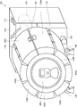
- FIG. 1 is a front perspective view showing an overall configuration when the cooling device 100 according to the present embodiment is used.
- the cooling device 100 mainly includes a main body 110, a plurality of cooling members 150A, 150B, and connecting members 170, 170,... For connecting the cooling members 150A, 150B,. And hooks 160 for connecting and removing the ends of the plurality of cooling members 150A, 150B..., A rear roller 120, and front rollers 130, 130.
- a motor 115 is mounted inside the main body 110.
- a switch 111 for turning on / off the driving of the motor 115 is disposed outside the main body 110.
- Each of the plurality of cooling members 150A, 150B,... Is inserted therein so that a cold storage agent described later can be taken out.
- Each of the plurality of cooling members 150 ⁇ / b> A, 150 ⁇ / b> B... Is made of a material having high thermal conductivity such as aluminum or copper on the side in contact with the can 200, i.e., the inner surface in a state of surrounding the can 200.
- each of the plurality of cooling members 150A, 150B,... Is composed of a material having a low thermal conductivity such as plastic or other heat insulating material on the opposite side of the can 200, that is, the outer surface in a state of surrounding the can 200. Is done.
- the plurality of cooling members 150A, 150B,... That connect the cooling members 150A, 150B,... are formed of an elastic member such as a spring or rubber. Therefore, it is easy to match the size of the plurality of cooling members 150A, 150B...
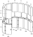
- FIG. 2 is a diagram showing a plurality of cooling members 150A, 150B,... When setting the regenerators 151, 151,... According to the present embodiment.
- FIG. 3 is a view showing a plurality of cooling members 150A, 150B... When setting the can 200 according to the present embodiment.
- the user cools a plurality of cool storage agents 151, 151,... In a freezer or a refrigerator in advance.
- a plurality of cool storage agents 151, 151... are filled with a solution having a freezing point lower than 0 ° C., such as saline.
- the regenerators 151, 151,... are made of a material such as vinyl that hardly corrodes.
- the cool storage agents 151, 151 ... are formed in the three-dimensional shape according to the shape inside the cooling member 150A, 150B .... Thereby, the clearance gap between the outer surface of the cool storage agents 151, 151 ... and the inner surfaces of the cooling members 150A, 150B ... becomes small, and the cooling efficiency can be improved.
- the user expands the plurality of cooling members 150 ⁇ / b> A, 150 ⁇ / b> B..., And converts the can 200 containing beverages such as beer and juice into the plurality of cooling members 150 ⁇ / b> A, 150 ⁇ / b> B. ..Mounted on the upper side, that is, the inside.
- the user wraps the side surface of the can 200 with a plurality of cooling members 150A, 150B.
- the can 200 is wound while slightly pulling the plurality of cooling members 150A, 150B,..., The gap between the can 200 and the plurality of cooling members 150A, 150B,.
- the user places the can 200 around which the plurality of cooling members 150 ⁇ / b> A, 150 ⁇ / b> B... Are wound on the rear roller 120 and the front roller 130.
- the motor 115 is driven to rotate the can 200 and the plurality of cooling members 150A, 150B,.
- the motor 115 may rotate the can 200 by driving the rear roller 120, or may rotate the can 200 via another member (not shown).
- a suction cup for attaching the bottom of the can 200 and a mechanism for transmitting the driving force of the motor 115 to the suction cup may be used.
- a timer may be mounted on the main body 110, and the driving of the motor 115 may be automatically stopped when a predetermined time, for example, 1 minute, 2 minutes, 3 minutes, or the like has elapsed.
- the cooling device 100 As described above, in the cooling device 100 according to the present embodiment, a part or all of the connecting members 170, 170... Have elasticity, so that the space between the plurality of cooling members 150A, 150B.
- the size of the gap can be easily adjusted according to the size of the can 200. That is, the user can easily set the cans 200 of various sizes in the cooling device 100.
- the cooling device 100 according to the present embodiment is not limited to the can 200, and other containers can be easily set and quickly cooled.
- FIG. 4 is a front perspective view showing the cooling device 100 that cools the beer bottle 250 according to the present embodiment.
- the cooling device 100 according to the present embodiment can easily set and quickly cool a bottle 250 or a plastic bottle of beverages such as beer and juice.
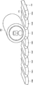
- FIG. 5 is a front sectional view showing the cooling members 150A, 150B... And the hook 160 according to the present embodiment.
- hook 160 includes a first member 162 attached to one end of a plurality of cooling members 150A, 150B... And a plurality of cooling members 150A, 150B. And a second member 163 attached to the other end of the first member 162 and hooked on the first member 162.
- an elastic member 164 such as a spring is attached to the first member 162 at a position where the second member 163 contacts.
- the frame itself of the second member 163 may have elasticity.
- the size of the gap between the ends of the plurality of cooling members 150A, 150B,... can be easily adjusted to the size of the can 200. Can be adjusted. That is, according to the size of the can 200, the user can easily set the can 200 in the cooling device 100B.
- the cooling device 100B according to the present embodiment is not limited to the can 200, and other containers can be easily set and quickly cooled.
- FIG. 6 is a front sectional view showing cooling members 150A, 150B... And magnets 165, 166 according to the present embodiment.
- hook 160 according to the present embodiment includes a first magnet 165 attached to one end of a plurality of cooling members 150A, 150B... And a plurality of cooling members 150A, 150B. A second magnet 166 attached to the other end and pulling on the first magnet 165.
- the state in which the can 200 is surrounded by the plurality of cooling members 150A, 150B,... Is maintained by utilizing the force with which the hook 160 is pulled by the magnet. Therefore, the size of the gap between the end portions of the plurality of cooling members 150A, 150B... Can be easily adjusted according to the size of the can 200. That is, according to the size of the can 200, the user can easily set the can 200 in the cooling device 100C. Furthermore, the cooling device 100C according to the present embodiment is not limited to the can 200, and other containers can be easily set and quickly cooled.
- the hook 160 not only the hook 160 but a part or all of the connecting members 170, 170... May have a magnetic force instead of elasticity.
- a magnet may be attached to a part or all of the hook 160 and / or the connecting members 170, 170... Via an elastic member such as a spring.
- the connecting members 170, 170... And the hook 160 can adjust the length of the circumferential gap of the cooling member 150A, 150B.
- a member may be used.
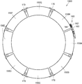
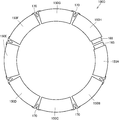
- FIG. 7 is a front view showing a plurality of cooling members 150A, 150B... According to the present embodiment.
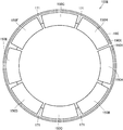
- FIG. 8 is a front view showing a plurality of cooling members 150A, 150B,... According to the present embodiment for showing another form of the cover.
- the cover 173 can be attached to the joints between the ends of the plurality of cooling members 150A, 150B.
- one end of the cover 173 is attached to one end of the plurality of cooling members 150 ⁇ / b> A, 150 ⁇ / b> B...
- an attachment member 173 ⁇ / b> X such as a hook-and-loop fastener or a magnet is attached to the other end of the cover 173.
- the attachment member 173Y such as a hook-and-loop fastener and a magnet, which can be connected to the attachment member 173X is attached to the other ends of the plurality of cooling members 150A, 150B.
- the plurality of cooling members 150A, 150B,... are directly pulled together.
- the gap distance between the plurality of cooling members 150A, 150B,... Is indirectly reduced.
- FIG. 9 is a front view showing a plurality of cooling members 150A, 150B... According to the present embodiment.
- a plurality of cooling members 150A, 150B... According to the present embodiment are connected by covers 171 and 171.
- the ends of the plurality of cooling members 150 ⁇ / b> A, 150 ⁇ / b> B... Are configured to be connectable by hooks 160.
- the periphery of the plurality of cooling members 150A, 150B... Is bound by the belt 180. That is, as shown in FIGS. 1 and 2, the user winds the can 200 or the like with the plurality of cooling members 150A, 150B... And then the plurality of cooling members 150A, 150B. Tighten.
- hook-and-loop fasteners 180X and 180Y are attached to both ends of the belt 180. Thereby, the user can adjust the overlap state of the hook-and-loop fastener according to the size of the can 200.
- the belt 180 itself may have elasticity.
- the user can easily set the can 200 in the cooling device 100E according to the size of the can 200.
- the cooling device 100E according to the present embodiment is not limited to the can 200, and other containers can be easily set and quickly cooled.
- FIG. 10 is a front view showing a plurality of cooling members 150A, 150B,... According to the present embodiment for showing another form of the belt.
- magnet 190X, 190Y is attached to the both ends of the belt 190 concerning this Embodiment.
- the belt 190 itself may have elasticity.
- a plurality of cooling members 150A, 150B,... Can be brought into close contact with the outer periphery of the can 200 by utilizing the force with which the ends of the belt 190 pull. That is, according to the size of the can 200, the user can easily set the can 200 in the cooling device 100E.
- the cooling device 100E according to the present embodiment is not limited to the can 200, and other containers can be easily set and quickly cooled.
- the driving force of the motor 115 is used to rotate the can 200 and the plurality of cooling members 150A, 150B,.
- FIG. 11 is a front perspective view showing the cooling device 100F according to the present embodiment.
- handle 118 is rotatably attached to main body 110. The user rotates the can 200 and the plurality of cooling members 150A, 150B,... By turning the handle 118.
- the handle 118 may rotate the can 200 by driving the rear roller 120, or may rotate the can 200 via other members (not shown).
- a suction cup for attaching the bottom of the can 200 and a mechanism for transmitting the driving force of the handle 118 to the suction cup may be used.
- the cooling device 100 is for cooling the can 200 alone.
- the refrigerator 1 in which the cooling device 100 for quickly cooling the can 200 and the like is mounted will be described.
- a plurality of cooling members 150A, 150B,... are supplied with an airframe cooled by a heat pump of the refrigerator 1 instead of a regenerator.
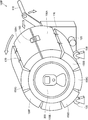
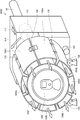
- FIG. 12 is a front view showing the inside of the refrigerator 1 according to the present embodiment.
- FIG. 13 is a side cross-sectional view of the refrigerator 1 according to the present embodiment.
- FIG. 14 is a front perspective view showing a cooling device 100G mounted on the refrigerator 1 according to the present embodiment.
- the refrigerator 1 includes a cabinet 2 having a heat insulating box. Inside the cabinet 2, a refrigerator compartment 3, a freezer compartment 4, and a vegetable compartment 5 are provided in this order from above.
- the refrigerator compartment 3 stores the stored items in a refrigerator
- the freezer compartment 4 stores the stored items in a frozen state.
- the vegetable room 5 is maintained at a higher temperature than the refrigerated room 3 and refrigerates stored items such as vegetables.
- the refrigerator compartment 3 is opened and closed by a rotating door 3a pivoted at one end.
- the freezer compartment 4 and the vegetable compartment 5 are opened and closed by drawer type doors 4a and 5a formed integrally with a storage case (not shown), respectively.
- First and second cold air passages 7 and 8 communicating with each other via dampers (not shown) are provided on the back surfaces of the freezer compartment 4 and the refrigerator compartment 3.
- a discharge port 7 a and a return port 7 b that face the freezer compartment 4 are opened in the first cold air passage 7.
- a discharge port 8 a facing the refrigerator compartment 3 is opened in the second cold air passage 8.
- a communication path (not shown) that connects the refrigerator compartment 3 and the vegetable compartment 5 is provided.
- the vegetable compartment 5 has a return port 7c for returning cool air to the evaporator 20.
- a machine room 6 is provided behind the vegetable room 5 in the cabinet 2, and a compressor 10 for operating a refrigeration cycle is installed in the machine room 6.
- the refrigeration cycle is operated by driving the compressor 10, and the high-temperature and high-pressure refrigerant compressed by the compressor 10 is condensed while dissipating heat in the condenser, thereby cooling the refrigerant.
- the high temperature refrigerant is squeezed by the capillary tube, expands to a low temperature and low pressure, and is sent to the evaporator 20.
- the liquid-phase refrigerant flowing into the evaporator 20 exchanges heat with the air flowing through the first cold air passage 7, evaporates while absorbing heat, and is sent to the compressor 10 as a low-temperature gas refrigerant. Accordingly, the refrigerant circulates to operate the refrigeration cycle, and cold air is generated by the airflow exchanged with the evaporator 20.
- the cold air discharged from the discharge port 7a circulates in the freezer compartment 4, and the cold air that has taken heat from the stored items in the freezer compartment 4 is returned to the evaporator 20 in the first cold air passage 7 through the return port 7b. .
- the cold air discharged from the discharge port 8a circulates in the refrigerator compartment 3, and then is discharged to the vegetable compartment 5 through the communication path and circulates through the vegetable compartment 5.
- the cold air that has taken heat from the stored items in the refrigerator compartment 3 and the vegetable compartment 5 is returned to the evaporator 20 in the first cold air passage 7 through the return port 7c.
- the apparatus 100G for cooling is arrange
- the inside of a plurality of cooling members 150A, 150B,... Penetrates in the front-rear direction, and the cold air blown out from discharge port 8a
- the cold air passes through the plurality of cooling members 150 ⁇ / b> A, 150 ⁇ / b> B... And blows out from the front part to the refrigerator compartment 3.
- cooling device 100G Since other configurations of cooling device 100G are the same as those in the first to sixth embodiments, description thereof will not be repeated here.
- the user performs the following operation when quickly cooling the uncooled can 200. That is, the user attaches a plurality of cooling members 150A, 150B,... To the can 200 and places them on the cooling device 100G. And the guidance path
- the cooling device 100G may be mounted in the refrigerator 1 in advance. More specifically, the guide path 99 is previously attached to the discharge port 8a. Then, the cooling device 100G is placed inside the refrigerator compartment 3 so that the rear part thereof is in front of the discharge port 8a of the guide path 99. In this case, when quickly cooling the uncooled can 200, the user attaches a plurality of cooling members 150 ⁇ / b> A, 150 ⁇ / b> B to the can 200 and places them on the cooling device 100 ⁇ / b> G in the refrigerator 1. Switch 111 is turned on.
- a timer may be mounted on the main body 110, and the driving of the motor 115 may be automatically stopped when a predetermined time, for example, 1 minute, 2 minutes, 3 minutes, or the like has elapsed.
- the cooling device 100G As described above, also in the refrigerator 1 equipped with the cooling device 100G according to the present embodiment, since the connecting members 170, 170... Have elasticity, the gaps between the plurality of cooling members 150A, 150B. Can be easily adjusted in accordance with the size of the can 200. That is, according to the size of the can 200, the user can easily set the can 200 in the cooling device 100G. Furthermore, the cooling device 100G according to the present embodiment is not limited to the can 200, and other containers can be easily set and quickly cooled. ⁇ Eighth Embodiment>
- the regenerators 151, 151... Can be taken in and out of the cooling members 150A, 150B.
- the cool storage agents 151, 151... May not be able to be put in and out of the cooling members 150A, 150B.
- a cold storage agent contained in a bag is used as a countermeasure against rust, but the bag may not be taken out.
- the cooling members 150 ⁇ / b> A, 150 ⁇ / b> B... May directly include a liquid regenerator.
- the regenerator can be replaced with a new one as to the form in which the regenerator can be taken out. Furthermore, it becomes possible to replace the cool storage agent with another cool storage agent having a different temperature range. For example, it is possible to cool the baby bottle using the cooling device 100 and then manufacture ice cream.
- the plurality of cooling members 150A, 150B,... For enclosing the periphery of the cooling objects 200, 250 and the size of the cooling objects 200, 250 are determined.
- At least one adjusting member biases the plurality of cooling members in the direction of narrowing the gaps between the plurality of cooling members 150A, 150B.
- the cooling devices 100, 100B,... Further include a detaching member 160 for detaching at least two cooling members among the plurality of cooling members. Prepare.
- the detachable member 160 has elasticity.
- At least one adjusting member includes at least one connecting member 170, 170... For connecting a plurality of cooling members. At least one of the connecting members 170, 170 ... has elasticity.
- the at least one adjusting member includes the belts 180 and 190 that bind around the plurality of cooling members.
- the belts 180 and 190 have elasticity.
- the cooling device 100 further includes covers 171, 172, and 173 ⁇ ⁇ that cover the gaps between the plurality of cooling members.
- the cooling devices 100, 100B,... Further include a plurality of cool storage agents 151, 151,.
- Each of the plurality of cool storage agents 151, 151... Has a shape along the shape of the plurality of cooling members 150A, 150B.
- the refrigerator 1 including the cooling devices 100, 100B,.
- the refrigerator 1 includes a cool air outlet 8a and a path 99 for supplying the cool air blown from the outlet to the plurality of cooling members 150A, 150B,.
- Refrigerator 3 Refrigerating room 4: Freezer room 5: Vegetable room 6: Machine room 7: 1st cold air passage 7a: Discharge port 8: 2nd cold air passage 8a: Air outlet 10: Compressor 99: Route 100: For cooling Device 110: Main body 111: Switch 115: Motor 118: Handle 120: Rear roller 130: Front roller 150A: Cooling member 151: Cold storage agent 160: Hook 162: First member 163: Second member 164: Elastic member 165: first magnet 166: second magnet 170: coupling member 171: cover 172: cover 173: cover 173X: mounting member 173Y: mounting member 180: belt 180X: hook-and-loop fastener 180Y: hook-and-loop fastener 190: belt 190X: magnet 190Y: Magnet 200: Can 250: Bottle
Landscapes
- Engineering & Computer Science (AREA)
- Chemical & Material Sciences (AREA)
- Combustion & Propulsion (AREA)
- Physics & Mathematics (AREA)
- Mechanical Engineering (AREA)
- Thermal Sciences (AREA)
- General Engineering & Computer Science (AREA)
- Cold Air Circulating Systems And Constructional Details In Refrigerators (AREA)
- Devices That Are Associated With Refrigeration Equipment (AREA)
Abstract
L'invention concerne un dispositif de refroidissement qui est plus facile à utiliser que les dispositifs classiques, et un réfrigérateur équipé dudit dispositif de refroidissement. La présente invention concerne un dispositif de refroidissement (100, 100B …) comportant : une pluralité d'éléments de refroidissement (150A, 150B …) destinée à entourer un objet à refroidir (200, 250); et au moins un élément de réglage (170, 160, 165, 166, 180, 190) destiné à ajuster les espacements entre la pluralité d'éléments de refroidissement (150A, 150B …) conformément à la taille de l'objet à refroidir (200, 250).
Applications Claiming Priority (2)
| Application Number | Priority Date | Filing Date | Title |
|---|---|---|---|
| JP2015-042207 | 2015-03-04 | ||
| JP2015042207A JP2016161253A (ja) | 2015-03-04 | 2015-03-04 | 冷却用装置および冷蔵庫 |
Publications (1)
| Publication Number | Publication Date |
|---|---|
| WO2016140108A1 true WO2016140108A1 (fr) | 2016-09-09 |
Family
ID=56846726
Family Applications (1)
| Application Number | Title | Priority Date | Filing Date |
|---|---|---|---|
| PCT/JP2016/055284 Ceased WO2016140108A1 (fr) | 2015-03-04 | 2016-02-23 | Dispositif de refroidissement et réfrigérateur |
Country Status (2)
| Country | Link |
|---|---|
| JP (1) | JP2016161253A (fr) |
| WO (1) | WO2016140108A1 (fr) |
Cited By (1)
| Publication number | Priority date | Publication date | Assignee | Title |
|---|---|---|---|---|
| WO2019026820A1 (fr) * | 2017-07-31 | 2019-02-07 | シャープ株式会社 | Matériau de stockage de chaleur latente, outil de refroidissement, boîte de refroidissement, récipient d'emballage de distribution et unité de refroidissement |
Citations (3)
| Publication number | Priority date | Publication date | Assignee | Title |
|---|---|---|---|---|
| JPS62112083U (fr) * | 1985-12-28 | 1987-07-16 | ||
| JP2002195711A (ja) * | 2000-10-20 | 2002-07-10 | Kawai Giken Co Ltd | 保冷又は蓄熱体 |
| JP3091931U (ja) * | 2002-08-05 | 2003-02-21 | 昌弘 寺田 | ビール瓶や他の飲料容器のための保冷具 |
Family Cites Families (3)
| Publication number | Priority date | Publication date | Assignee | Title |
|---|---|---|---|---|
| JPH07218084A (ja) * | 1994-01-31 | 1995-08-18 | Aisin Seiki Co Ltd | 保冷庫 |
| JP2006304850A (ja) * | 2005-04-26 | 2006-11-09 | Seyo Shin | 保温または保冷用の食器 |
| JP6054661B2 (ja) * | 2012-07-17 | 2016-12-27 | サントリーホールディングス株式会社 | 冷却装置、冷却システム、及び冷却加熱システム |
-
2015
- 2015-03-04 JP JP2015042207A patent/JP2016161253A/ja active Pending
-
2016
- 2016-02-23 WO PCT/JP2016/055284 patent/WO2016140108A1/fr not_active Ceased
Patent Citations (3)
| Publication number | Priority date | Publication date | Assignee | Title |
|---|---|---|---|---|
| JPS62112083U (fr) * | 1985-12-28 | 1987-07-16 | ||
| JP2002195711A (ja) * | 2000-10-20 | 2002-07-10 | Kawai Giken Co Ltd | 保冷又は蓄熱体 |
| JP3091931U (ja) * | 2002-08-05 | 2003-02-21 | 昌弘 寺田 | ビール瓶や他の飲料容器のための保冷具 |
Cited By (2)
| Publication number | Priority date | Publication date | Assignee | Title |
|---|---|---|---|---|
| WO2019026820A1 (fr) * | 2017-07-31 | 2019-02-07 | シャープ株式会社 | Matériau de stockage de chaleur latente, outil de refroidissement, boîte de refroidissement, récipient d'emballage de distribution et unité de refroidissement |
| CN110945101A (zh) * | 2017-07-31 | 2020-03-31 | 夏普株式会社 | 潜热蓄热材料、保冷器具、冷藏库、物流包装容器以及保冷单元 |
Also Published As
| Publication number | Publication date |
|---|---|
| JP2016161253A (ja) | 2016-09-05 |
Similar Documents
| Publication | Publication Date | Title |
|---|---|---|
| US8881545B2 (en) | Refrigerator | |
| US8745992B2 (en) | Refrigerator | |
| KR101570349B1 (ko) | 냉장고 | |
| US9182165B2 (en) | Rapid cryocooler utilizing spray holes to cool a beverage | |
| US10302345B2 (en) | Refrigerator | |
| US6427463B1 (en) | Methods for increasing efficiency in multiple-temperature forced-air refrigeration systems | |
| US10132552B2 (en) | Refrigerator having refrigeration system and ice maker within door and drain duct from ice maker to dispenser excess water tray | |
| KR102488190B1 (ko) | 제냉 시스템 | |
| WO2001084065A1 (fr) | Chambre froide isolante | |
| KR102679833B1 (ko) | 저장 용기 및 이를 포함하는 냉장고 | |
| CN107367120A (zh) | 冰箱 | |
| US20150107291A1 (en) | Refrigerator appliance | |
| CN112512380A (zh) | 饮料冷却器 | |
| CN106482429A (zh) | 冰箱 | |
| JP2016161253A (ja) | 冷却用装置および冷蔵庫 | |
| US20140116083A1 (en) | Refrigerator | |
| US20160370048A1 (en) | Ice making duct for refrigerator and ice making method of using the same | |
| KR20230147301A (ko) | 콜드체인 기반의 하이브리드형 이동식 냉온장고 | |
| ES2330252T3 (es) | Contenedor con placas eutecticas y refrigerador con tal contenedor. | |
| CN221483952U (zh) | 一种制冷设备 | |
| KR20140067204A (ko) | 식품의 수중저장방법 및 장치 | |
| JP6626721B2 (ja) | 冷却用装置および冷蔵庫 | |
| KR100614315B1 (ko) | 냉장고 | |
| KR100549076B1 (ko) | 냉장고 | |
| EP3933311A1 (fr) | Appareil de réfrigération |
Legal Events
| Date | Code | Title | Description |
|---|---|---|---|
| 121 | Ep: the epo has been informed by wipo that ep was designated in this application |
Ref document number: 16758802 Country of ref document: EP Kind code of ref document: A1 |
|
| NENP | Non-entry into the national phase |
Ref country code: DE |
|
| 122 | Ep: pct application non-entry in european phase |
Ref document number: 16758802 Country of ref document: EP Kind code of ref document: A1 |