WO2016140142A2 - 内容物放出構造ならびにこの内容物放出構造を備えたエアゾール式製品およびポンプ式製品 - Google Patents
内容物放出構造ならびにこの内容物放出構造を備えたエアゾール式製品およびポンプ式製品 Download PDFInfo
- Publication number
- WO2016140142A2 WO2016140142A2 PCT/JP2016/055649 JP2016055649W WO2016140142A2 WO 2016140142 A2 WO2016140142 A2 WO 2016140142A2 JP 2016055649 W JP2016055649 W JP 2016055649W WO 2016140142 A2 WO2016140142 A2 WO 2016140142A2
- Authority
- WO
- WIPO (PCT)
- Prior art keywords
- pattern
- content
- nozzle tip
- contents
- discharge hole
- Prior art date
- Legal status (The legal status is an assumption and is not a legal conclusion. Google has not performed a legal analysis and makes no representation as to the accuracy of the status listed.)
- Ceased
Links
Images


Classifications
-
- B—PERFORMING OPERATIONS; TRANSPORTING
- B65—CONVEYING; PACKING; STORING; HANDLING THIN OR FILAMENTARY MATERIAL
- B65D—CONTAINERS FOR STORAGE OR TRANSPORT OF ARTICLES OR MATERIALS, e.g. BAGS, BARRELS, BOTTLES, BOXES, CANS, CARTONS, CRATES, DRUMS, JARS, TANKS, HOPPERS, FORWARDING CONTAINERS; ACCESSORIES, CLOSURES, OR FITTINGS THEREFOR; PACKAGING ELEMENTS; PACKAGES
- B65D83/00—Containers or packages with special means for dispensing contents
- B65D83/14—Containers for dispensing liquid or semi-liquid contents by internal gaseous pressure, i.e. aerosol containers comprising propellant
- B65D83/75—Aerosol containers not provided for in groups B65D83/16 - B65D83/74
- B65D83/753—Aerosol containers not provided for in groups B65D83/16 - B65D83/74 characterised by details or accessories associated with outlets
-
- B—PERFORMING OPERATIONS; TRANSPORTING
- B05—SPRAYING OR ATOMISING IN GENERAL; APPLYING FLUENT MATERIALS TO SURFACES, IN GENERAL
- B05B—SPRAYING APPARATUS; ATOMISING APPARATUS; NOZZLES
- B05B1/00—Nozzles, spray heads or other outlets, with or without auxiliary devices such as valves, heating means
- B05B1/14—Nozzles, spray heads or other outlets, with or without auxiliary devices such as valves, heating means with multiple outlet openings; with strainers in or outside the outlet opening
-
- B—PERFORMING OPERATIONS; TRANSPORTING
- B05—SPRAYING OR ATOMISING IN GENERAL; APPLYING FLUENT MATERIALS TO SURFACES, IN GENERAL
- B05B—SPRAYING APPARATUS; ATOMISING APPARATUS; NOZZLES
- B05B15/00—Details of spraying plant or spraying apparatus not otherwise provided for; Accessories
- B05B15/60—Arrangements for mounting, supporting or holding spraying apparatus
- B05B15/65—Mounting arrangements for fluid connection of the spraying apparatus or its outlets to flow conduits
-
- B—PERFORMING OPERATIONS; TRANSPORTING
- B65—CONVEYING; PACKING; STORING; HANDLING THIN OR FILAMENTARY MATERIAL
- B65D—CONTAINERS FOR STORAGE OR TRANSPORT OF ARTICLES OR MATERIALS, e.g. BAGS, BARRELS, BOTTLES, BOXES, CANS, CARTONS, CRATES, DRUMS, JARS, TANKS, HOPPERS, FORWARDING CONTAINERS; ACCESSORIES, CLOSURES, OR FITTINGS THEREFOR; PACKAGING ELEMENTS; PACKAGES
- B65D83/00—Containers or packages with special means for dispensing contents
-
- B—PERFORMING OPERATIONS; TRANSPORTING
- B65—CONVEYING; PACKING; STORING; HANDLING THIN OR FILAMENTARY MATERIAL
- B65D—CONTAINERS FOR STORAGE OR TRANSPORT OF ARTICLES OR MATERIALS, e.g. BAGS, BARRELS, BOTTLES, BOXES, CANS, CARTONS, CRATES, DRUMS, JARS, TANKS, HOPPERS, FORWARDING CONTAINERS; ACCESSORIES, CLOSURES, OR FITTINGS THEREFOR; PACKAGING ELEMENTS; PACKAGES
- B65D83/00—Containers or packages with special means for dispensing contents
- B65D83/14—Containers for dispensing liquid or semi-liquid contents by internal gaseous pressure, i.e. aerosol containers comprising propellant
- B65D83/141—Containers for dispensing liquid or semi-liquid contents by internal gaseous pressure, i.e. aerosol containers comprising propellant specially adapted for specific contents or propellants
Definitions
- the present invention relates to a content discharge structure in which a nozzle tip having a content discharge hole portion to an external space region is attached to an output side cylindrical portion as a content passage region.
- a part of the spreading pattern restricting portion for setting the flow direction of the contents flowing out from the discharge hole portion of the nozzle tip to the external space region is placed on the output side tubular portion to which the nozzle tip is attached. It is related with the content discharge
- the contents flowing out from the discharge hole portion of the nozzle tip are prevented from spreading in any specific direction by the action of the spread pattern restricting portion.
- This content discharge structure can be installed in each of aerosol type products and pump type products.
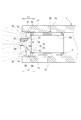
- the output side cylindrical portion and the discharge hole side in each longitudinal direction of the nozzle tip are referred to as “front”, and the opposite side (right side in FIG. 1) is referred to as “rear”.
- the vertical direction in FIG. 1 is denoted as “left and right” and “horizontal”, and the vertical direction in FIG.
- This conventional spreading pattern restricting portion is provided in the form of a diffusion dividing groove in the vertical direction in the vicinity of the content discharge hole portion of the nozzle tip. That is, a diffusion split groove is formed in a part of the nozzle tip having the content discharge hole portion.
- the present invention is based on a new focus on the formation position of the spreading pattern restricting portion with respect to the content discharge hole portion of the nozzle tip.
- the front end inward surface portion of the output side cylindrical portion is used as the discharge content from the nozzle tip outer end side hole portion. It is used as a spread pattern restricting section.
- the present invention aims to reduce the place restrictions in forming each of the discharge hole portion of the nozzle tip and the spread pattern restricting portion, and to enrich the content discharge pattern to the external space area.
- a cylindrical nozzle tip for example, a nozzle tip 2 described later
- discharge holes for example, an upper opening surface 2d, a lower opening surface 2j, and a central hole 2q, which will be described later
- the output side cylindrical portion is A spreading pattern restricting portion (for example, pattern upper restricting surfaces 1d and 1d ′ and pattern lower restricting surfaces 1e and 1e ′ described later) for setting the flow direction of the contents flowing out from the discharge hole portion of the nozzle tip to the external space region.
- the nozzle tip is Provided with an outer end side hole as the discharge hole (for example, an upper opening surface 2d and a lower opening surface 2j described later),
- the output side cylindrical portion is A front end inward surface portion as the pattern restricting portion (for example, pattern upper restricting surfaces 1d and 1d ′, pattern lower restricting surfaces 1e and 1e ′ described later),
- the thing of a structure aspect is used.
- the nozzle tip is The pattern restricting portions are inserted in the front and rear directions of different output side tubular portions having different lengths in the front and rear direction (for example, L1 and L2 to be described later), and held in a manner of arrangement of the pattern restricting portions at predetermined positions.
- L1 and L2 different lengths in the front and rear direction
- the contents discharge structure having such a configuration and the aerosol type product and the pump type product provided with the content release structure are objects of the present invention.
- the present invention is based on the above problem solving means.
- (11) In the formation of each of the nozzle chip discharge hole portion and its spreading pattern restricting portion, it is possible to reduce the place restrictions and to enrich the content discharge pattern to the external space area, (12) A nozzle tip with a common specification is attached to the output side tubular portion of the type in which the length of the spread pattern restricting portion formed on the output side tubular portion to be attached with the nozzle tip is different. The nozzle tip can be used effectively. Has the effect of.
- the content discharge structure of the present invention can be used by being mounted on both the aerosol type product and the pump type product.
- an aerosol type product is assumed as necessary.
- the constituent elements (for example, the outer cylindrical portion 1a) of the reference numbers with alphabets used in the respective drawings are part of the constituent elements (for example, the push buttons 1) of the numeral portions of the reference numbers. .
- 1 is a well-known push button for contents discharge operation
- 1a is an outer cylindrical portion (output-side cylindrical portion) that is formed in the front-rear direction on the downstream side of the push button and acts as a content outlet to the external space
- 1b is formed on the front inner peripheral surface of the outer cylindrical portion 1a in the circumferential direction, and an annular concave portion for engaging and holding an annular convex portion 2b described later
- 1c is a circular opening formed in a so-called virtual front end portion of the outer cylindrical portion 1a
- Reference numerals 1d and 1d ′ denote pattern upper restricting surfaces (1d: used in FIGS. 1 to 3; 1d ′: FIG.
- Reference numerals 1e and 1e ′ denote pattern lower regulation surfaces (1e: FIG. 1 to FIG. 3) that are formed on the lower side adjacent portions of the circular opening 1c in a plane manner parallel to the pattern upper regulation surface 1d.
- 1f is a rear vertical plane portion that is formed in the left and right adjacent portions of the circular opening 1c in a plane mode with the front-rear direction as a normal line, and abuts a front vertical plane portion 2v described later;
- L1 is the length in the front-rear direction of the pattern upper regulating surface 1d and the pattern lower regulating surface 1e,
- L2 ( ⁇ L1) is the length in the front-rear direction of each of the pattern upper regulating surface 1d 'and the pattern lower regulating surface 1e'.
- 2 is a nozzle tip attached to the outer cylindrical part 1a and acting as a content discharge part to the external space area;
- 2a is a so-called content passage area of the nozzle tip, and is an inner cylindrical portion in close contact with the inner peripheral surface of the outer cylindrical portion 1a,
- 2b is formed in a circumferential direction on the rear outer peripheral surface of the inner cylindrical portion 2a, and is a hook-shaped annular convex portion that is engaged and held by the annular concave portion 1b of the outer cylindrical portion 1a.
- 2c is a flat plate portion for discharge operation continuously formed in a rectangular flat plate shape from the inner cylindrical portion 2a in the lateral direction adjacent to the front side thereof; 2d is set on the upper end side of the central portion in the horizontal direction of the flat plate-like portion 2c, for example, in the form of a rear rising surface (see FIG. 1) inclined by 45 degrees, and serves as a so-called interface with the external space.
- Open surface (outer end side hole as discharge hole), 2e is an upper notch-shaped portion that is continuously formed on the outlet side of the upper opening surface 2d in a substantially V-shaped manner when viewed from the front, and regulates the spread of the contents discharged from the upper opening surface, 2f is an upper end side opening area which is a component of the upper notch portion 2e, 2g is a substantially V-shaped inner surface that is a component of the upper notch-shaped portion 2e, 2h is a component of the upper notch-like portion 2e and is a rear upper vertical surface continuous with the substantially V-shaped inner surface 2g; 2j is set on the lower end side of the central portion in the horizontal direction of the flat plate-like portion 2c, for example, in the form of a rear-falling surface (see FIG.
- Open surface (outer end side hole as discharge hole), 2k is a lower notch portion as a pattern lower regulating surface that is continuously formed on the outlet side of the lower opening surface 2j in a substantially V-shaped manner when viewed from the front, and regulates the spread of the contents discharged from the lower opening surface;
- 2m is a lower end side opening area which is a component of the lower notch 2k
- 2n is a substantially inverted V-shaped inner surface that is a component of the lower notch portion 2k
- 2p is a component of the lower notch portion 2k and is a rear lower vertical surface continuous with the substantially inverted V-shaped inner surface 2n
- 2q is a central hole portion (discharge hole portion) for discharging contents formed in a central portion between the upper notch portion 2e and the lower notch portion 2k of the flat plate-like portion 2c
- 2r is a forward-facing cylindrical mountain-shaped portion that is located between the upper notch-
- 2s is a pair of slope surfaces formed on the front left and right sides of the forward cylindrical mountain-shaped portion 2r with an upward slope toward the center
- 2t is a pair of pattern-regulating convex portions formed on the upper and lower portions continuous from the central hole portion of the vertical top surface sandwiched by the slope surface 2s and having the central hole portion 2q
- 2u is an opposing surface portion of the pair of pattern restricting convex portions 2t
- 2v is a rear surface of the flat plate-like portion 2c, and is formed on the left and right side portions of the inner cylindrical portion 2a in a plane manner with the front-rear direction as a normal line, and is in contact with the rear vertical plane portion 1f, Respectively.
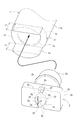
- A is a reverse diaper-like spreading pattern at the upper position where the spread of the contents discharged from the upper opening surface 2d of the nozzle chip 2 is regulated by the pattern upper regulating surface 1d and the upper cutout portion 2e
- B is a bellows-like spreading pattern at a lower position where the spread of the contents discharged from the lower opening surface 2j of the nozzle chip 2 is regulated by the pattern lower regulating surface 1e and the lower notch portion 2k
- C is a horizontally long elliptical spreading pattern at the middle position in the vertical direction in which the spread of the contents discharged from the central hole 2q of the nozzle tip 2 is regulated by a pair of upper and lower pattern center regulating surfaces 2u; Respectively.
- the pattern upper regulating surfaces 1d and 1d ′ and the pattern lower regulating surfaces 1e and 1e ′ are formed at positions near the downstream of the upper opening surface 2d and the lower opening surface 2j, respectively.
- the pattern upper regulating surfaces 1d and 1d 'and the pattern lower regulating surfaces 1e and 1e' act as front end inward surface portions of the pattern regulating portions, respectively.
- the press button 1 and the nozzle tip 2 are made of plastic made of polypropylene, polyethylene, polyacetal, nylon, polybutylene terephthalate, or the like.
- the basic features of the illustrated content release structure according to the present invention are: (21) Form pattern upper restricting surfaces 1d, 1d 'and pattern lower restricting surfaces 1e, 1e' on the outer cylindrical portion 1a of the push button 1, (22)
- the pattern upper restricting surfaces 1d and 1d 'and the pattern lower restricting surfaces 1e and 1e' respectively constitute an upper end side opening area 2f constituting the upper discharge hole portion of the nozzle chip 2 and a lower end constituting the lower discharge hole portion. Opposing to the side opening area 2m, That is.
- the upper and lower end portions of the spreading pattern restricting portion intended for the contents flowing out from the upper end side opening area 2f and the lower end side opening area 2m of the nozzle chip 2 are not the nozzle chip itself but the outer cylinder of the attachment destination. It is formed in the shape part 1a.
- valve action part When a known valve action part (not shown) is opened by, for example, a downward operation of the push button 1 and the contents are released, the contents of the container body (not shown) are transferred to the valve action part and the stem (not shown). And flows into the outer cylindrical portion 1a.
- This inflow operation is of course a well-known action.
- the contents flowing into the outer cylindrical portion 1a pass through the inner cylindrical portion 2a, and then pass through the upper opening surface 2d, the central hole portion 2q, and the lower opening surface 2j from a total of three discharge hole portions in the external space region. Is output.
- the spreading pattern of each content flowing out from the three discharge holes in the vertical direction formed in the nozzle tip 2 is: (31) In the case of contents flowing out from the upper opening surface 2d as the upper discharge hole portion, in addition to the substantially V-shaped inner surface 2g and the rear upper vertical surface 2h of the nozzle tip 2, the pattern upper limit of the outer cylindrical portion 1a Regulated by surfaces 1d, 1d ' (32) In the case of the contents flowing out from the central hole 2q as the middle discharge hole, the contents are regulated by the pair of pattern central regulating surfaces 2u of the nozzle chip 2 provided at the upper and lower positions in an opposed and spaced state, (33) In the case of contents flowing out from the lower opening surface 2j as the lower discharge hole portion, in addition to the substantially inverted V-shaped inner surface 2n and the rear lower vertical surface 2p of the nozzle tip 2, the lower side of the pattern of the outer cylindrical portion 1a It is regulated by the regulation surfaces 1e and 1e '.
- the lower end portion of the inverted rice cake-like spreading pattern A overlaps with the upper center portion in the horizontal direction of the horizontally long elliptical spreading pattern C, and the upper end portion of the rice ball-like spreading pattern B overlaps with the central upper end portion of the horizontally long elliptical spreading pattern C. ing.
- the outer cylindrical portion 1a disclosed in FIGS. 1 to 3 differs from that disclosed in FIG. 4 in the lengths L1 and L2 in the front-rear direction of the pattern upper regulating surfaces 1d and 1d ′ and the pattern lower regulating surfaces 1e and 1e ′. ing.
- the length L1 in the front-rear direction of the outer cylindrical portion 1a disclosed in FIGS. 1 to 3 is larger than the length L2 of the outer cylindrical portion 1a disclosed in FIG. That is, “L1> L2” is set.
- the nozzle tip 2 is located behind the front opening of the outer cylindrical portion 1a. (51) It is inserted deeply into the pattern upper regulating surface 1d and the pattern lower regulating surface 1e having a length L1 in the front-rear direction, (52) It is inserted shallowly into the pattern upper regulating surface 1d 'and the pattern lower regulating surface 1e having a length L2 in the front-rear direction shorter than this.
- the content discharge structure of FIG. 1 causes the upward spreading of the outflow contents from the upper opening surface 2d of the nozzle chip 2 and the outflow from the lower opening surface 2j than in FIG. In other words, the spread of the contents below is strongly regulated.
- the nozzle tip 2 of the common specification has the front vertical plane portion 2v as the rear vertical plane portion 1f.
- the ring-shaped convex portion 2b is held substantially in contact with the ring-shaped concave portion 1b.
- the lengths in the front-rear direction of the annular concave portion 1b and the rear vertical plane portion 1f in the different types of outer cylindrical portions 1a of FIGS. 1 and 4 are the same set value.
- the present invention is not limited to the above embodiments, for example, (61) Arbitrary part which continues the upper opening surface 2d, the upper notch-like part 2e and the lower opening surface 2j, and the lower notch-like part 2k as the content discharge hole from the front end side internal space area of the inner cylindrical part 2a An arbitrary number is provided in (62) The central hole portion 2q is omitted, and the other content discharge hole portions in the vertical position are used. (63) The pattern upper regulating surfaces 1d and 1d 'and the pattern lower regulating surfaces 1e and 1e' are set to curved surface shapes. (64) Using a trigger lever type content discharge operation part, the outer cylindrical part 1a is set in the form of a separate member from this operation part, You may do it.
- Aerosol-type products and pump-type products to which the present invention is applied include cleaning agents, cleaning agents, cooling agents, muscle anti-inflammatory agents, hair restorers, hair dyes, hair styling agents, hair treatment agents, sunscreens, lotions, Cleansing agent, antiperspirant, cosmetics, shaving foam, food, droplets (such as vitamins), pharmaceuticals, quasi drugs, horticultural agents, insecticides, pest repellents, animal repellents, deodorants, There are various applications such as laundry, fire extinguisher, paint, adhesive, lubricant, urethane foam.
- the contents stored in the container body are in various forms such as liquid, cream and gel.
- Ingredients blended in the contents are, for example, powders, oil ingredients, alcohols, surfactants, polymer compounds, active ingredients according to each application, water, and the like.
- metal salt powder inorganic powder, resin powder, etc.
- talc kaolin, aluminum hydroxychloride (aluminum salt), calcium alginate, gold powder, silver powder, mica, carbonate, magnesium chloride, silica, zinc oxide, titanium oxide, zeolite, nylon powder, barium sulfate, cellulose, and mixtures thereof Etc. are used.
- Oil components include silicone oils such as dimethylpolysiloxane, ester oils such as isopropyl myristate, oils such as palm oil, eucalyptus oil, camellia oil, olive oil, jojoba oil, hydrocarbon oils such as liquid paraffin, myristic acid, palmitic acid. Fatty acids such as acid, stearic acid, linoleic acid, and linolenic acid are used.
- monohydric lower alcohols such as ethanol
- monohydric higher alcohols such as lauryl alcohol
- polyhydric alcohols such as ethylene glycol, glycerin, and 1,3-butylene glycol are used.
- Surfactants include anionic surfactants such as sodium lauryl sulfate, nonionic surfactants such as polyoxyethylene alkyl ether and polyglycerin fatty acid ester, amphoteric surfactants such as lauryldimethylaminoacetic acid betaine, alkyl chloride A cationic surfactant such as trimethylammonium is used.
- polymer compound hydroxyethyl cellulose, methyl cellulose, gelatin, starch, casein, xanthan gum, carboxyvinyl polymer, or the like is used.
- Active ingredients according to each application include dyes such as paraphenylenediamine and aminophenol, oxidizing agents such as hydrogen peroxide, setting agents such as acrylic resins and waxes, and ultraviolet light such as 2-ethylhexyl paramethoxycinnamate.
- Absorbents vitamins such as retinol and dl- ⁇ -tocopherol, moisturizers such as hyaluronic acid, anti-inflammatory analgesics such as methyl salicylate and indomethacin, antibacterial agents such as sodium benzoate and cresol, pests such as pyrethroid and diethyltoluamide Repellents, antiperspirants such as zinc paraphenolsulfonate, softeners such as camphor and menthol, anti-asthma drugs such as ephedrine and adrenaline, sweeteners such as sucralose and aspartame, adhesives and paints such as epoxy resin and urethane, Paraphenylenediamine, aminoph Dyes such as Nord, oxidizing agents such as hydrogen peroxide, ammonium dihydrogen phosphate, a fire extinguishing agent such as sodium bicarbonate, potassium used.
- moisturizers such as hyaluronic acid
- anti-inflammatory analgesics such
- suspending agents emulsifiers, antioxidants, sequestering agents and the like other than the above contents can also be used.
- a compressed gas such as carbon dioxide, nitrogen gas, compressed air, oxygen gas, rare gas, or a mixed gas thereof, or a liquefied gas such as liquefied petroleum gas, dimethyl ether, or fluorocarbon is used.
- Nozzle tip 2a Inner cylindrical portion 2b: Ring convex portion 2c: Flat plate portion 2d: Upper opening surface (discharge hole portion) 2e: Upper cutout portion 2f: Upper end side opening area 2g: Substantially V-shaped inner surface 2h: Rear upper vertical surface 2j: Lower opening surface (discharge hole) 2k: Lower notch portion 2m: Opening area 2n on the lower end side: Substantially inverted V-shaped inner surface 2p: Rear lower vertical surface 2q: Center hole (discharge hole) 2r: forward-facing cylindrical mountain-shaped portion 2s: a pair of slope surfaces 2t: a pair of pattern restricting convex portions 2u: a pair of upper and lower pattern center restricting surfaces 2v: a front vertical plane portion
Landscapes
- Chemical & Material Sciences (AREA)
- Dispersion Chemistry (AREA)
- Engineering & Computer Science (AREA)
- Mechanical Engineering (AREA)
- Containers And Packaging Bodies Having A Special Means To Remove Contents (AREA)
- Nozzles (AREA)
Abstract
ノズルチップの放出孔部から外部空間域に流出する内容物の流れ方向設定用の広がりパターン規制部を備えた内容物放出構造に関し、この広がりパターン規制部形成の場所的制約の減少化、外部空間域への内容物放出パターンの豊富化、およびノズルチップの有効利用化を図る。 押圧ボタン1と一体の出力側筒状部1aに取り付けられるノズルチップ2は、外部空間域への内容物放出用の外端側孔部2d,2jおよび中央孔部2qを備えている。この上下外端側孔部2d,2jそれぞれの下流近傍には上端側開口域2fおよび下端側開口域2mが設定され、これら上下端の各開口域に対する平面上の広がりパターン規制部1d,1eを、ノズルチップ2ではなく、出力側筒状部1aの側に形成している。広がりパターン規制部1d,1eの前後方向長さL1が異なる複数の出力側筒状部1a,1aに共通仕様のノズルチップ2を取り付けることも開示している。
Description
本発明は、外部空間域への内容物の放出孔部を備えたノズルチップが内容物通路域としての出力側筒状部に取り付けられた内容物放出構造に関する。
特に、ノズルチップの放出孔部から外部空間域に流出する内容物の流れ方向設定用の広がりパターン規制部の一部を、ノズルチップが取り付けられる出力側筒状部に、この内容物放出孔部の下流近傍の位置態様で設けた内容物放出構造に関する。
ここで、ノズルチップの放出孔部から流出する内容物はそこでの広がりパターン規制部の作用により任意の特定方向への広がりが阻止される。
この流出内容物の特定方向への広がり阻止作用により、内容物の放出孔部およびこれに対応した広がりパターン規制部それぞれの位置,形状などのいわば選択的設定に基づく、種々の内容物放出パターンが生成される。
また、広がりパターン規制部の前後方向(ノズルチップ挿入方向)の長さが異なる各種タイプの出力側筒状部に対しても、共通仕様のノズルチップを挿入・保持して用いることができる。
この内容物放出構造は、エアゾール式製品およびポンプ式製品のそれぞれに搭載可能である。
本明細書では、出力側筒状部およびノズルチップの各長手方向における放出孔部側(図1の左側)を「前」、その反対側(図1の右側)を「後」と記し、また、図1の紙面垂直方向を「左右」,「横」、同図の上下方向を「縦」と記す。
従来、ノズルチップの内容物放出孔部に広がりパターン規制部を設けた内容物放出構造は提案されている(特許文献1の図8参照)。
この従来の広がりパターン規制部は、ノズルチップの、内容物放出孔部の近傍上下方向に拡散割溝の形で設けられている。すなわち、内容物放出孔部を有するノズルチップの一部に拡散割溝が形成されている。
本発明は、このようなノズルチップの内容物放出孔部に対する広がりパターン規制部の形成位置についての、新たな着眼に基づくものである。
ここではノズルチップが内容物通路域としての出力側筒状部に取り付けられることに着目し、この出力側筒状部の前端内向き面部分を、ノズルチップ外端側孔部からの放出内容物の広がりパターン規制部として用いている。
本発明はこれにより、ノズルチップの放出孔部およびその広がりパターン規制部それぞれの形成に際しての、場所的制約の減少化を図り、外部空間域への内容物放出パターンの豊富化を図ることを目的とする。
さらには、広がりパターン規制部の前後方向長さが異なるタイプの出力側筒状部に共通仕様のノズルチップを取り付けて、出力側筒状部に対応した個々の広がりパターンが生成される形にし、これによりノズルチップの有効利用化を図ることを目的とする。
本発明は、以上の課題を次のようにして解決する。
(1)外部空間域への内容物の放出孔部(例えば後述の上開口面2d,下開口面2j,中央孔部2q)を備えた筒状のノズルチップ(例えば後述のノズルチップ2)が内容物通路域としての出力側筒状部(例えば後述の外側円筒状部1a)に取り付けられた内容物放出構造において、
前記出力側筒状部は、
前記ノズルチップの放出孔部から外部空間域に流出する内容物の流れ方向設定用の広がりパターン規制部(例えば後述のパターン上側規制面1d,1d′,パターン下側規制面1e,1e′)を、前記放出孔部(例えば後述の上開口面2d,下開口面2j)の下流近傍位置に備えた、
構成態様のものを用いる。
(2)上記(1)において、
前記ノズルチップは、
前記放出孔部としての外端側孔部(例えば後述の上開口面2d,下開口面2j)を備え、
前記出力側筒状部は、
前記パターン規制部(例えば後述のパターン上側規制面1d,1d′,パターン下側規制面1e,1e′)としての前端内向き面部分を備えた、
構成態様のものを用いる。
(3)上記(1),(2)において、
前記ノズルチップは、
前記パターン規制部の前後方向長さ(例えば後述のL1,L2)が異なる別々の前記出力側筒状部の前後方向にそれぞれ挿入されて、前記パターン規制部の所定位置への配設態様で保持される共通仕様の、
構成態様のものを用いる。
(1)外部空間域への内容物の放出孔部(例えば後述の上開口面2d,下開口面2j,中央孔部2q)を備えた筒状のノズルチップ(例えば後述のノズルチップ2)が内容物通路域としての出力側筒状部(例えば後述の外側円筒状部1a)に取り付けられた内容物放出構造において、
前記出力側筒状部は、
前記ノズルチップの放出孔部から外部空間域に流出する内容物の流れ方向設定用の広がりパターン規制部(例えば後述のパターン上側規制面1d,1d′,パターン下側規制面1e,1e′)を、前記放出孔部(例えば後述の上開口面2d,下開口面2j)の下流近傍位置に備えた、
構成態様のものを用いる。
(2)上記(1)において、
前記ノズルチップは、
前記放出孔部としての外端側孔部(例えば後述の上開口面2d,下開口面2j)を備え、
前記出力側筒状部は、
前記パターン規制部(例えば後述のパターン上側規制面1d,1d′,パターン下側規制面1e,1e′)としての前端内向き面部分を備えた、
構成態様のものを用いる。
(3)上記(1),(2)において、
前記ノズルチップは、
前記パターン規制部の前後方向長さ(例えば後述のL1,L2)が異なる別々の前記出力側筒状部の前後方向にそれぞれ挿入されて、前記パターン規制部の所定位置への配設態様で保持される共通仕様の、
構成態様のものを用いる。
このような構成からなる内容物放出構造ならびに当該内容物放出構造を備えたエアゾール式製品およびポンプ式製品を本発明の対象としている。
本発明は以上の課題解決手段により、
(11)ノズルチップの放出孔部およびその広がりパターン規制部それぞれの形成に際しての、場所的制約の減少化を図り、外部空間域への内容物放出パターンの豊富化を図ることができ、
(12)ノズルチップの取付け対象の出力側筒状部に形成される広がりパターン規制部の前後方向長さが異なるタイプの当該出力側筒状部に対し、共通仕様のノズルチップが取り付けられる形にして、ノズルチップの有効利用化を図ることができる、
といった効果を奏している。
(11)ノズルチップの放出孔部およびその広がりパターン規制部それぞれの形成に際しての、場所的制約の減少化を図り、外部空間域への内容物放出パターンの豊富化を図ることができ、
(12)ノズルチップの取付け対象の出力側筒状部に形成される広がりパターン規制部の前後方向長さが異なるタイプの当該出力側筒状部に対し、共通仕様のノズルチップが取り付けられる形にして、ノズルチップの有効利用化を図ることができる、
といった効果を奏している。
図1~図4を用いて本発明を実施するための形態を説明する。
上述したように、本発明の内容物放出構造はエアゾール式製品およびポンプ式製品の双方にそれぞれ搭載して使用されえるが、以下の記載では単なる説明の便宜上、必要に応じてエアゾール式製品を前提とする。
なお、原則として、各図で用いるアルファベット付き参照番号の構成要素(例えば外側円筒状部1a)は当該参照番号の数字部分の構成要素(例えば押圧ボタン1)の一部であることを示している。
図1~図4において、
1は内容物放出操作用の周知の押圧ボタン,
1aは当該押圧ボタンの下流側前後方向に形成され、外部空間域への内容物流出路として作用する外側円筒状部(出力側筒状部),
1bは外側円筒状部1aの前側内周面にその周方向態様で形成され、後述の環凸状部2bを係合保持するための環凹状部,
1cは外側円筒状部1aのいわば仮想的な前端部分に形成された円開口部,
1d,1d′は前後左右方向の平面態様で円開口部1cの上側隣部分に形成された、広がりパターン規制部としてのパターン上側規制面(1d:図1~図3で使用,1d′:図4で使用),
1e,1e′はパターン上側規制面1dと平行な平面態様で円開口部1cの下側隣部分に形成された、広がりパターン規制部としてのパターン下側規制面(1e:図1~図3で使用,1e′:図4で使用),
1fは前後方向を法線とする平面態様で円開口部1cの左右隣部分に形成され、後述の前側縦平面部2vと当接する後側縦平面部,
L1はパターン上側規制面1dおよびパターン下側規制面1eそれぞれの前後方向長さ,
L2(<L1)はパターン上側規制面1d′およびパターン下側規制面1e′それぞれの前後方向長さ,
をそれぞれ示している。
1は内容物放出操作用の周知の押圧ボタン,
1aは当該押圧ボタンの下流側前後方向に形成され、外部空間域への内容物流出路として作用する外側円筒状部(出力側筒状部),
1bは外側円筒状部1aの前側内周面にその周方向態様で形成され、後述の環凸状部2bを係合保持するための環凹状部,
1cは外側円筒状部1aのいわば仮想的な前端部分に形成された円開口部,
1d,1d′は前後左右方向の平面態様で円開口部1cの上側隣部分に形成された、広がりパターン規制部としてのパターン上側規制面(1d:図1~図3で使用,1d′:図4で使用),
1e,1e′はパターン上側規制面1dと平行な平面態様で円開口部1cの下側隣部分に形成された、広がりパターン規制部としてのパターン下側規制面(1e:図1~図3で使用,1e′:図4で使用),
1fは前後方向を法線とする平面態様で円開口部1cの左右隣部分に形成され、後述の前側縦平面部2vと当接する後側縦平面部,
L1はパターン上側規制面1dおよびパターン下側規制面1eそれぞれの前後方向長さ,
L2(<L1)はパターン上側規制面1d′およびパターン下側規制面1e′それぞれの前後方向長さ,
をそれぞれ示している。
また、図1~図4において、
2は外側円筒状部1aに取り付けられ、外部空間域への内容物放出部として作用するノズルチップ,
2aは当該ノズルチップのいわば内容物通路域であって、外側円筒状部1aの内周面に密接する内側円筒状部,
2bは内側円筒状部2aの後側外周面にその周方向態様で形成され、外側円筒状部1aの環凹状部1bに係合保持される鍔形状の環凸状部,
2cは内側円筒状部2aからその前隣横方向に長方形平板態様で連続形成された放出作動用の平板状部,
2dは平板状部2cの横方向中央部分の上端側に例えば45度傾斜の後上がり面(図1参照)の態様で設定され、外部空間域とのいわばインタフェースとして作用する内容物放出用の上開口面(放出孔部としての外端側孔部),
2eは上開口面2dの出口側に正面視が略V字状の態様で連続形成され、当該上開口面から放出される内容物の広がりを規制するパターン上規制面としての上切欠状部分,
2fは上切欠状部分2eの構成要素である上端側開口域,
2gは上切欠状部分2eの構成要素である略V字状内面,
2hは上切欠状部分2eの構成要素であって略V字状内面2gと連続する後上垂直面,
2jは平板状部2cの横方向中央部分の下端側に例えば45度傾斜の後下がり面(図1参照)の態様で設定され、外部空間域とのいわばインタフェースとして作用する内容物放出用の下開口面(放出孔部としての外端側孔部),
2kは下開口面2jの出口側に正面視が略V字状の態様で連続形成され、当該下開口面から放出される内容物の広がりを規制するパターン下規制面としての下切欠状部分,
2mは下切欠状部分2kの構成要素である下端側開口域,
2nは下切欠状部分2kの構成要素である略逆V字状内面,
2pは下切欠状部分2kの構成要素であって略逆V字状内面2nと連続する後下垂直面,
2qは平板状部2cの、上切欠状部分2eと下切欠状部分2kとの間の中央部分に形成された内容物放出用の中央孔部(放出孔部),
2rは上切欠状部分2eと下切欠状部分2kとの間に位置して、その前面中央から前後方向に中央孔部2qが形成されている前向き円筒山状部,
2sは前向き円筒山状部2rの前面左右両側に中央側への上り傾斜で形成された一対のスロープ面,
2tはスロープ面2sに挟まれて中央孔部2qを有する縦方向頂面の当該中央孔部から連続する上下各部分に形成された一対のパターン規制用凸状部,
2uは一対のパターン規制用凸状部2tの対向面部分であって中央孔部2qから放出される内容物の広がりを規制する上下一対のパターン中央規制面,
2vは平板状部2cの後面であって、前後方向を法線とする平面態様で内側円筒状部2aの左右両側部分に形成され、後側縦平面部1fと当接する前側縦平面部,
をそれぞれ示している。
2は外側円筒状部1aに取り付けられ、外部空間域への内容物放出部として作用するノズルチップ,
2aは当該ノズルチップのいわば内容物通路域であって、外側円筒状部1aの内周面に密接する内側円筒状部,
2bは内側円筒状部2aの後側外周面にその周方向態様で形成され、外側円筒状部1aの環凹状部1bに係合保持される鍔形状の環凸状部,
2cは内側円筒状部2aからその前隣横方向に長方形平板態様で連続形成された放出作動用の平板状部,
2dは平板状部2cの横方向中央部分の上端側に例えば45度傾斜の後上がり面(図1参照)の態様で設定され、外部空間域とのいわばインタフェースとして作用する内容物放出用の上開口面(放出孔部としての外端側孔部),
2eは上開口面2dの出口側に正面視が略V字状の態様で連続形成され、当該上開口面から放出される内容物の広がりを規制するパターン上規制面としての上切欠状部分,
2fは上切欠状部分2eの構成要素である上端側開口域,
2gは上切欠状部分2eの構成要素である略V字状内面,
2hは上切欠状部分2eの構成要素であって略V字状内面2gと連続する後上垂直面,
2jは平板状部2cの横方向中央部分の下端側に例えば45度傾斜の後下がり面(図1参照)の態様で設定され、外部空間域とのいわばインタフェースとして作用する内容物放出用の下開口面(放出孔部としての外端側孔部),
2kは下開口面2jの出口側に正面視が略V字状の態様で連続形成され、当該下開口面から放出される内容物の広がりを規制するパターン下規制面としての下切欠状部分,
2mは下切欠状部分2kの構成要素である下端側開口域,
2nは下切欠状部分2kの構成要素である略逆V字状内面,
2pは下切欠状部分2kの構成要素であって略逆V字状内面2nと連続する後下垂直面,
2qは平板状部2cの、上切欠状部分2eと下切欠状部分2kとの間の中央部分に形成された内容物放出用の中央孔部(放出孔部),
2rは上切欠状部分2eと下切欠状部分2kとの間に位置して、その前面中央から前後方向に中央孔部2qが形成されている前向き円筒山状部,
2sは前向き円筒山状部2rの前面左右両側に中央側への上り傾斜で形成された一対のスロープ面,
2tはスロープ面2sに挟まれて中央孔部2qを有する縦方向頂面の当該中央孔部から連続する上下各部分に形成された一対のパターン規制用凸状部,
2uは一対のパターン規制用凸状部2tの対向面部分であって中央孔部2qから放出される内容物の広がりを規制する上下一対のパターン中央規制面,
2vは平板状部2cの後面であって、前後方向を法線とする平面態様で内側円筒状部2aの左右両側部分に形成され、後側縦平面部1fと当接する前側縦平面部,
をそれぞれ示している。
また、図3において
Aはノズルチップ2の上開口面2dから放出される内容物の広がりが、パターン上側規制面1dおよび上切欠状部分2eで規制された上位置の逆おむすび状広がりパターン,
Bはノズルチップ2の下開口面2jから放出される内容物の広がりが、パターン下側規制面1eおよび下切欠状部分2kで規制された下位置のおむすび状広がりパターン,
Cはノズルチップ2の中央孔部2qから放出される内容物の広がりが、上下一対のパターン中央規制面2uで規制された上下方向中間位置の横長楕円状広がりパターン,
をそれぞれ示している。
Aはノズルチップ2の上開口面2dから放出される内容物の広がりが、パターン上側規制面1dおよび上切欠状部分2eで規制された上位置の逆おむすび状広がりパターン,
Bはノズルチップ2の下開口面2jから放出される内容物の広がりが、パターン下側規制面1eおよび下切欠状部分2kで規制された下位置のおむすび状広がりパターン,
Cはノズルチップ2の中央孔部2qから放出される内容物の広がりが、上下一対のパターン中央規制面2uで規制された上下方向中間位置の横長楕円状広がりパターン,
をそれぞれ示している。
ここで、パターン上側規制面1d,1d′およびパターン下側規制面1e,1e′はそれぞれ上開口面2dおよび下開口面2jの下流近傍位置に形成されている。
また、パターン上側規制面1d,1d′およびパターン下側規制面1e,1e′はそれぞれパターン規制部の前端内向き面部分として作用する。
押圧ボタン1およびノズルチップ2はポリプロピレン,ポリエチレン,ポリアセタール,ナイロン,ポリブチレンテレフタレートなどからなるプラスチック製のものである。
本発明にかかる図示の内容物放出構造の基本的特徴は、
(21)押圧ボタン1の外側円筒状部1aにパターン上側規制面1d,1d′およびパターン下側規制面1e,1e′を形成し、
(22)このパターン上側規制面1d,1d′およびパターン下側規制面1e,1e′がそれぞれ、ノズルチップ2の上放出孔部を構成する上端側開口域2fおよび下放出孔部を構成する下端側開口域2mに対向している、
ことである。
(21)押圧ボタン1の外側円筒状部1aにパターン上側規制面1d,1d′およびパターン下側規制面1e,1e′を形成し、
(22)このパターン上側規制面1d,1d′およびパターン下側規制面1e,1e′がそれぞれ、ノズルチップ2の上放出孔部を構成する上端側開口域2fおよび下放出孔部を構成する下端側開口域2mに対向している、
ことである。
すなわち、ノズルチップ2の上端側開口域2fおよび下端側開口域2mのそれぞれから流出する内容物を対象とした広がりパターン規制部の上下端部分が、ノズルチップ自体ではなく、その取付け先の外側円筒状部1aに形成されている。
このように、ノズルチップ2の放出用孔部の上端側開口域2f,下端側開口域2mそれぞれから流出する内容物の広がりパターン規制部の一部を、当該ノズルチップに設けるのではなく、それが取り付けられる押圧ボタン1の外側円筒状部1aに設けている。
ここでは、これまでのノズルチップ2の放出用孔部から流出する内容物の広がりパターン規制部はあくまで当該ノズルチップ自体の放出用孔部近傍に設けるといった固定観念を払拭している。
押圧ボタン1の例えば下動操作により周知の弁作用部(図示省略)が開いて内容物放出状態に移行すると、容器本体(図示省略)の内容物が、弁作用部およびステム(図示省略)などを経て外側円筒状部1aへと流入する。この流入動作は勿論周知の作用である。
外側円筒状部1aへ流入した内容物は、内側円筒状部2aを経て、その上開口面2d,中央孔部2qおよび下開口面2jの上下方向の計三個の放出孔部から外部空間域へと出力される。
ここで、ノズルチップ2に形成された上下方向計三個の放出孔部から流出する各内容物の広がりパターンは、
(31)上放出孔部としての上開口面2dから流出する内容物の場合、ノズルチップ2の略V字状内面2gおよび後上垂直面2hに加えて、外側円筒状部1aのパターン上側規制面1d,1d′により規制され、
(32)中放出孔部としての中央孔部2qから流出する内容物の場合、その上下各位置に対向離間状態で設けたノズルチップ2の一対のパターン中央規制面2uによって規制され、
(33)下放出孔部としての下開口面2jから流出する内容物の場合、ノズルチップ2の略逆V字状内面2nおよび後下垂直面2pに加えて、外側円筒状部1aのパターン下側規制面1e,1e′により規制される。
(31)上放出孔部としての上開口面2dから流出する内容物の場合、ノズルチップ2の略V字状内面2gおよび後上垂直面2hに加えて、外側円筒状部1aのパターン上側規制面1d,1d′により規制され、
(32)中放出孔部としての中央孔部2qから流出する内容物の場合、その上下各位置に対向離間状態で設けたノズルチップ2の一対のパターン中央規制面2uによって規制され、
(33)下放出孔部としての下開口面2jから流出する内容物の場合、ノズルチップ2の略逆V字状内面2nおよび後下垂直面2pに加えて、外側円筒状部1aのパターン下側規制面1e,1e′により規制される。
これら(31)~(33)の広がりパターン規制により、図3で示すように、
(41)上開口面2dからの流出内容物は逆おむすび状広がりパターンAの形に設定され、
(42)中央孔部2qからの流出内容物は横長楕円状広がりパターンCの形に設定され、
(43)下開口面2jからの流出内容物はおむすび状広がりパターンBの形に設定される。
(41)上開口面2dからの流出内容物は逆おむすび状広がりパターンAの形に設定され、
(42)中央孔部2qからの流出内容物は横長楕円状広がりパターンCの形に設定され、
(43)下開口面2jからの流出内容物はおむすび状広がりパターンBの形に設定される。
逆おむすび状広がりパターンAの下端部分は横長楕円状広がりパターンCの横方向中央上端部分と重なり、また、おむすび状広がりパターンBの上端部分は横長楕円状広がりパターンCの横方向中央上端部分と重なっている。
図1~図3で開示の外側円筒状部1aと図4で開示のそれとは、パターン上側規制面1d,1d′およびパターン下側規制面1e,1e′の前後方向長さL1,L2が異なっている。
図1~図3で開示の外側円筒状部1aにおける前後方向長さL1は図4で開示の外側円筒状部1aの長さL2よりも大きい。すなわち「L1>L2」に設定されている。
このようにパターン上側規制面1d,1d′およびパターン下側規制面1e,1e′の前後方向長さL1,L2を異ならせた別タイプの外側円筒状部1aに、いわば共通タイプのノズルチップ2が取り付けられている。
図1および図4からもあきらかなように、ノズルチップ2は、外側円筒状部1aの前開口部からその後方に、
(51)前後方向長さL1のパターン上側規制面1dおよびパターン下側規制面1eに対して深く挿入され、
(52)これよりも短い前後方向長さL2のパターン上側規制面1d′およびパターン下側規制面1eに対して浅く挿入されている。
(51)前後方向長さL1のパターン上側規制面1dおよびパターン下側規制面1eに対して深く挿入され、
(52)これよりも短い前後方向長さL2のパターン上側規制面1d′およびパターン下側規制面1eに対して浅く挿入されている。
この挿入程度の違いにより、図4よりも図1の内容物放出構造の方が、ノズルチップ2の上開口面2dからの流出内容物の上方への広がりを、また下開口面2jからの流出内容物の下方への広がりをそれぞれいわば強く規制している。
なお、この図1,図4の前後方向長さL1,L2いずれの外側円筒状部1aの場合にも、共通仕様のノズルチップ2は、その前側縦平面部2vが後側縦平面部1fに略当接し、かつ、その環凸状部2bが環凹状部1bに係合した状態で保持される。
すなわち、図1および図4のそれぞれ別タイプの外側円筒状部1aにおける環凹状部1bと後側縦平面部1fとの前後方向長さは同じ設定値である。
本発明が以上の実施形態に限定されないことは勿論であり例えば、
(61)内容物放出用孔部としての上開口面2d,上切欠状部分2eおよび下開口面2j,下切欠状部分2kを、内側円筒状部2aの前端側内部空間域から続く任意の部分に、任意の個数設ける、
(62)中央孔部2qを省略し、それ以外の上下位置の内容物放出用孔部などを用いる、
(63)パターン上側規制面1d,1d′およびパターン下側規制面1e,1e′を曲面形状に設定する、
(64)トリガレバー形式の内容物放出操作部を用い、この操作部とは別部材の形で外側円筒状部1aを設定する、
ようにしてもよい。
(61)内容物放出用孔部としての上開口面2d,上切欠状部分2eおよび下開口面2j,下切欠状部分2kを、内側円筒状部2aの前端側内部空間域から続く任意の部分に、任意の個数設ける、
(62)中央孔部2qを省略し、それ以外の上下位置の内容物放出用孔部などを用いる、
(63)パターン上側規制面1d,1d′およびパターン下側規制面1e,1e′を曲面形状に設定する、
(64)トリガレバー形式の内容物放出操作部を用い、この操作部とは別部材の形で外側円筒状部1aを設定する、
ようにしてもよい。
本発明が適用されるエアゾール式製品およびポンプ式製品としては、洗浄剤,清掃剤,冷却剤,筋肉消炎剤,育毛剤,染毛剤,ヘアスタイリング剤,ヘアトリートメント剤,日焼け止め,化粧水,クレンジング剤,制汗剤,化粧品,シェービングフォーム,食品,液滴状のもの(ビタミンなど),医薬品,医薬部外品,園芸用剤,殺虫剤,害虫忌避剤,動物忌避剤,消臭剤,洗濯のり,消火器,塗料,接着剤,潤滑剤,ウレタンフォームなどの各種用途のものがある。
容器本体に収容される内容物としては、液状,クリーム状,ゲル状など種々の形態のものを用いる。内容物に配合される成分は例えば、粉状物,油成分,アルコール類,界面活性剤,高分子化合物,各用途に応じた有効成分,水などである。
粉状物としては、金属塩類粉末,無機物粉末や樹脂粉末などを用いる。例えば、タルク,カオリン,アルミニウムヒドロキシクロライド(アルミ塩),アルギン酸カルシウム,金粉,銀粉,雲母,炭酸塩,塩化マグネシウム,シリカ,酸化亜鉛,酸化チタン,ゼオライト,ナイロンパウダー,硫酸バリウム,セルロース,これらの混合物などを用いる。
油成分としては、ジメチルポリシロキサンなどのシリコーン油,ミリスチン酸イソプロピルなどのエステル油,パーム油,ユーカリ油,ツバキ油,オリーブ油,ホホバ油などの油脂,流動パラフィンなどの炭化水素油,ミリスチン酸,パルミチン酸,ステアリン酸,リノール酸,リノレン酸などの脂肪酸などを用いる。
アルコール類としては、エタノールなどの1価の低級アルコール,ラウリルアルコールなどの1価の高級アルコール,エチレングリコール,グリセリン,1,3-ブチレングリコールなどの多価アルコールなどを用いる。
界面活性剤としては、ラウリル硫酸ナトリウムなどのアニオン性界面活性剤,ポリオキシエチレンアルキルエーテルやポリグリセリン脂肪酸エステルなどの非イオン性界面活性剤,ラウリルジメチルアミノ酢酸ベタインなどの両性界面活性剤,塩化アルキルトリメチルアンモニウムなどのカチオン性界面活性剤などを用いる。
高分子化合物としては、ヒドロキシエチルセルロース,メチルセルロース,ゼラチン,デンプン,カゼイン,キサンタンガム,カルボキシビニルポリマーなどを用いる。
各用途に応じた有効成分としては、パラフェニレンジアミン,アミノフェノールなどの染料,過酸化水素水などの酸化剤,アクリル系樹脂やワックスなどのセット剤,パラメトキシケイ皮酸2-エチルヘキシルなどの紫外線吸収剤,レチノールやdl-α-トコフェロールなどのビタミン,ヒアルロン酸などの保湿剤,サリチル酸メチル,インドメタシンなどの消炎鎮痛剤,安息香酸ナトリウム,クレゾールなどの除菌剤,ピレスロイド,ジエチルトルアミドなどの害虫忌避剤,パラフェノールスルホン酸亜鉛などの制汗剤,カンフル,メントールなどの清涼剤,エフェドリン,アドレナリンなどの抗喘息薬,スクラロース,アスパルテームなどの甘味料,エポキシ樹脂,ウレタンなどの接着剤や塗料,パラフェニレンジアミン,アミノフェノールなどの染料,過酸化水素水などの酸化剤,リン酸二水素アンモニウム,炭酸水素ナトリウム・カリウムなどの消火剤などを用いる。
さらに、上記内容物以外の、懸濁剤,乳化剤,酸化防止剤,金属イオン封鎖剤なども用いることができる。
内容物放出射用の噴射剤としては、炭酸ガス,窒素ガス,圧縮空気,酸素ガス,希ガス,これらの混合ガスなどの圧縮ガスや、液化石油ガス,ジメチルエーテル,フロロカーボンなどの液化ガスを用いる。
1:押圧ボタン
1a:外側円筒状部
1b:環凹状部
1c:円開口部
1d,1d′:パターン上側規制面(1d:図1~図3で使用,1d′:図4で使用)
1e,1e′:パターン下側規制面(1e:図1~図3で使用,1e′:図4で使用)
1f:後側縦平面部
L1:パターン上側規制面1d,パターン下側規制面1eの前後方向長さ
L2(<L1):パターン上側規制面1d′,パターン下側規制面1e′の前後方向長さ
1a:外側円筒状部
1b:環凹状部
1c:円開口部
1d,1d′:パターン上側規制面(1d:図1~図3で使用,1d′:図4で使用)
1e,1e′:パターン下側規制面(1e:図1~図3で使用,1e′:図4で使用)
1f:後側縦平面部
L1:パターン上側規制面1d,パターン下側規制面1eの前後方向長さ
L2(<L1):パターン上側規制面1d′,パターン下側規制面1e′の前後方向長さ
2:ノズルチップ
2a:内側円筒状部
2b:環凸状部
2c:平板状部
2d:上開口面(放出孔部)
2e:上切欠状部分
2f:上端側開口域
2g:略V字状内面
2h:後上垂直面
2j:下開口面(放出孔部)
2k:下切欠状部分
2m:下端側開口域
2n:略逆V字状内面
2p:後下垂直面
2q:中央孔部(放出孔部)
2r:前向き円筒山状部
2s:一対のスロープ面
2t:一対のパターン規制用凸状部
2u:上下一対のパターン中央規制面
2v:前側縦平面部
2a:内側円筒状部
2b:環凸状部
2c:平板状部
2d:上開口面(放出孔部)
2e:上切欠状部分
2f:上端側開口域
2g:略V字状内面
2h:後上垂直面
2j:下開口面(放出孔部)
2k:下切欠状部分
2m:下端側開口域
2n:略逆V字状内面
2p:後下垂直面
2q:中央孔部(放出孔部)
2r:前向き円筒山状部
2s:一対のスロープ面
2t:一対のパターン規制用凸状部
2u:上下一対のパターン中央規制面
2v:前側縦平面部
(図3において)
A:上位置の逆おむすび状広がりパターン
B:下位置のおむすび状広がりパターン
C:上下方向中間位置の横長楕円状広がりパターン
A:上位置の逆おむすび状広がりパターン
B:下位置のおむすび状広がりパターン
C:上下方向中間位置の横長楕円状広がりパターン
Claims (5)
- 外部空間域への内容物の放出孔部を備えた筒状のノズルチップが内容物通路域としての出力側筒状部に取り付けられた内容物放出構造において、
前記出力側筒状部は、
前記ノズルチップの放出孔部から外部空間域に流出する内容物の流れ方向設定用の広がりパターン規制部を、前記放出孔部の下流近傍位置に備えている、
ことを特徴とする内容物放出構造。 - 前記ノズルチップは、
前記放出孔部としての外端側孔部を備え、
前記出力側筒状部は、
前記パターン規制部としての前端内向き面部分を備えている、
ことを特徴とする請求項1記載の内容物放出構造。 - 前記ノズルチップは、
前記パターン規制部の前後方向長さが異なる別々の前記出力側筒状部の前後方向にそれぞれ挿入されて、前記パターン規制部の所定位置への配設態様で保持される共通仕様のものである、
ことを特徴とする請求項1または2記載の内容物放出構造。 - 請求項1乃至3のいずれかに記載の内容物放出構造を備え、かつ、噴射剤および放出対象内容物を収容した、
ことを特徴とするエアゾール式製品。 - 請求項1乃至3のいずれかに記載の内容物放出構造を備え、かつ、放出対象内容物を収容した、
ことを特徴とするポンプ式製品。
Priority Applications (1)
| Application Number | Priority Date | Filing Date | Title |
|---|---|---|---|
| JP2017503444A JP6482100B2 (ja) | 2015-03-02 | 2016-02-25 | 内容物放出構造ならびにこの内容物放出構造を備えたエアゾール式製品およびポンプ式製品 |
Applications Claiming Priority (2)
| Application Number | Priority Date | Filing Date | Title |
|---|---|---|---|
| JP2015-040214 | 2015-03-02 | ||
| JP2015040214 | 2015-03-02 |
Publications (2)
| Publication Number | Publication Date |
|---|---|
| WO2016140142A2 true WO2016140142A2 (ja) | 2016-09-09 |
| WO2016140142A3 WO2016140142A3 (ja) | 2016-10-27 |
Family
ID=56848878
Family Applications (1)
| Application Number | Title | Priority Date | Filing Date |
|---|---|---|---|
| PCT/JP2016/055649 Ceased WO2016140142A2 (ja) | 2015-03-02 | 2016-02-25 | 内容物放出構造ならびにこの内容物放出構造を備えたエアゾール式製品およびポンプ式製品 |
Country Status (2)
| Country | Link |
|---|---|
| JP (1) | JP6482100B2 (ja) |
| WO (1) | WO2016140142A2 (ja) |
Family Cites Families (6)
| Publication number | Priority date | Publication date | Assignee | Title |
|---|---|---|---|---|
| US3556411A (en) * | 1968-05-22 | 1971-01-19 | Nordson Corp | Spray nozzle |
| JPS6456158A (en) * | 1987-08-25 | 1989-03-03 | Toyo Seikan Kaisha Ltd | Nozzle for coating and repairing method of welded part |
| JP3695551B2 (ja) * | 1996-03-08 | 2005-09-14 | 株式会社いけうち | 二流体ノズル |
| JP3167653U (ja) * | 2011-02-18 | 2011-05-12 | 株式会社ユー・ピー・シー | 食用油用噴射器 |
| JP6032873B2 (ja) * | 2011-07-14 | 2016-11-30 | 小林製薬株式会社 | エアゾールボタン、エアゾールキャップおよびエアゾールボタンの噴射用ノズルチップ |
| JP6089006B2 (ja) * | 2014-06-26 | 2017-03-01 | 株式会社いけうち | スプレーノズル |
-
2016
- 2016-02-25 WO PCT/JP2016/055649 patent/WO2016140142A2/ja not_active Ceased
- 2016-02-25 JP JP2017503444A patent/JP6482100B2/ja active Active
Also Published As
| Publication number | Publication date |
|---|---|
| WO2016140142A3 (ja) | 2016-10-27 |
| JP6482100B2 (ja) | 2019-03-13 |
| JPWO2016140142A1 (ja) | 2017-12-14 |
Similar Documents
| Publication | Publication Date | Title |
|---|---|---|
| JP4867036B2 (ja) | 内容物放出機構ならびにこれを備えたエアゾール式製品およびポンプ式製品 | |
| JP5597893B2 (ja) | アクチュエータ倒立定量噴射機構および、このアクチュエータ倒立定量噴射機構を備えたエアゾール式製品 | |
| JP5455202B2 (ja) | 容器内容物の泡生成用アタッチメント,容器内容物の泡生成用アタッチメントを備えたポンプ式製品およびエアゾール式製品 | |
| WO2011138828A1 (ja) | 容器内容物の泡生成用アタッチメント,容器内容物の泡生成用アタッチメントを備えたポンプ式製品およびエアゾール式製品 | |
| JP2010142689A (ja) | 容器内容物の泡生成用アタッチメント,容器内容物の泡生成用アタッチメントを備えたポンプ式製品およびエアゾール式製品 | |
| JP6172844B2 (ja) | 噴射用ガス充填対応の正倒立バルブ機構およびこの正倒立バルブ機構を備えたエアゾール式製品 | |
| JP6570116B2 (ja) | 内容物放出機構およびこの内容物放出機構を備えたポンプ式製品 | |
| JP6099245B2 (ja) | 内容物放出口シャットオフ用のスパウトユニット、このスパウトユニットを組み込んだ内容物放出口シャットオフ機構、ならびにこの内容物放出口シャットオフ機構を用いたポンプ式製品およびエアゾール式製品 | |
| JP5991732B2 (ja) | エアゾール容器の逆定量噴射機構および、この逆定量噴射機構を備えたエアゾール式製品 | |
| JP6355197B2 (ja) | 内容物放出製品用カバー機構ならびにこの内容物放出製品用カバー機構を備えたエアゾール式製品およびポンプ式製品 | |
| JP2011042382A (ja) | 泡生成放出ユニット,内容物泡放出ポンプ機構および内容物泡放出ポンプ機構を備えたポンプ式製品 | |
| JP6482100B2 (ja) | 内容物放出構造ならびにこの内容物放出構造を備えたエアゾール式製品およびポンプ式製品 | |
| JP6853923B2 (ja) | 内容物放出構造ならびにこの内容物放出構造を備えたエアゾール式製品およびポンプ式製品 | |
| CN112469640A (zh) | 内容物喷射操作按钮和具备该内容物喷射操作按钮的气溶胶式产品 | |
| JP6859575B2 (ja) | 内容物放出機構およびこの内容物放出機構を備えたエアゾール式製品 | |
| JP2012091792A (ja) | 泡吐出式のポンプ機構およびこのポンプ機構を備えたポンプ式製品 | |
| JP5587143B2 (ja) | 連続作動モード設定機構および、この連続作動モード設定機構を備えたエアゾール式製品 | |
| JP6341609B2 (ja) | 内容物放出構造ならびにこの内容物放出構造を備えたエアゾール式製品およびポンプ式製品 | |
| WO2021029121A1 (ja) | エアゾール容器の逆定量噴射機構およびこの逆定量噴射機構を備えたエアゾール式製品 | |
| JP2016078870A (ja) | 内容物放出構造ならびにこの内容物放出構造を備えたエアゾール式製品およびポンプ式製品 | |
| JPWO2016181823A1 (ja) | 圧縮ガス対応の内容物ドロップ放出構造およびこの内容物ドロップ放出構造を備えた圧縮ガス式製品 | |
| JP2017213543A (ja) | 内容物噴射操作用ボタンおよびこの内容物噴射操作用ボタンを備えたエアゾール式製品 | |
| JP6552044B2 (ja) | 内容物放出操作ロック機構ならびにこの内容物放出操作ロック機構を備えたエアゾール式製品およびポンプ式製品 | |
| JP6562727B2 (ja) | パルス噴射機構およびこのパルス噴射機構を備えたエアゾール式製品 | |
| JP5477956B2 (ja) | 内容物放出量切換え機構ならびにこの機構を備えたエアゾール式製品およびポンプ式製品 |
Legal Events
| Date | Code | Title | Description |
|---|---|---|---|
| 121 | Ep: the epo has been informed by wipo that ep was designated in this application |
Ref document number: 16758836 Country of ref document: EP Kind code of ref document: A2 |
|
| ENP | Entry into the national phase |
Ref document number: 2017503444 Country of ref document: JP Kind code of ref document: A |
|
| NENP | Non-entry into the national phase |
Ref country code: DE |
|
| 122 | Ep: pct application non-entry in european phase |
Ref document number: 16758836 Country of ref document: EP Kind code of ref document: A2 |