WO2016140226A1 - Dispositif d'insertion de palier - Google Patents
Dispositif d'insertion de palier Download PDFInfo
- Publication number
- WO2016140226A1 WO2016140226A1 PCT/JP2016/056278 JP2016056278W WO2016140226A1 WO 2016140226 A1 WO2016140226 A1 WO 2016140226A1 JP 2016056278 W JP2016056278 W JP 2016056278W WO 2016140226 A1 WO2016140226 A1 WO 2016140226A1
- Authority
- WO
- WIPO (PCT)
- Prior art keywords
- axis direction
- bearing
- main body
- outer ring
- worm
- Prior art date
- Legal status (The legal status is an assumption and is not a legal conclusion. Google has not performed a legal analysis and makes no representation as to the accuracy of the status listed.)
- Ceased
Links
Images




Classifications
-
- B—PERFORMING OPERATIONS; TRANSPORTING
- B23—MACHINE TOOLS; METAL-WORKING NOT OTHERWISE PROVIDED FOR
- B23P—METAL-WORKING NOT OTHERWISE PROVIDED FOR; COMBINED OPERATIONS; UNIVERSAL MACHINE TOOLS
- B23P19/00—Machines for simply fitting together or separating metal parts or objects, or metal and non-metal parts, whether or not involving some deformation; Tools or devices therefor so far as not provided for in other classes
- B23P19/02—Machines for simply fitting together or separating metal parts or objects, or metal and non-metal parts, whether or not involving some deformation; Tools or devices therefor so far as not provided for in other classes for connecting objects by press fit or for detaching same
-
- B—PERFORMING OPERATIONS; TRANSPORTING
- B23—MACHINE TOOLS; METAL-WORKING NOT OTHERWISE PROVIDED FOR
- B23P—METAL-WORKING NOT OTHERWISE PROVIDED FOR; COMBINED OPERATIONS; UNIVERSAL MACHINE TOOLS
- B23P19/00—Machines for simply fitting together or separating metal parts or objects, or metal and non-metal parts, whether or not involving some deformation; Tools or devices therefor so far as not provided for in other classes
- B23P19/10—Aligning parts to be fitted together
-
- B—PERFORMING OPERATIONS; TRANSPORTING
- B23—MACHINE TOOLS; METAL-WORKING NOT OTHERWISE PROVIDED FOR
- B23P—METAL-WORKING NOT OTHERWISE PROVIDED FOR; COMBINED OPERATIONS; UNIVERSAL MACHINE TOOLS
- B23P21/00—Machines for assembling a multiplicity of different parts to compose units, with or without preceding or subsequent working of such parts, e.g. with program control
- B23P21/008—Machines for assembling a multiplicity of different parts to compose units, with or without preceding or subsequent working of such parts, e.g. with program control the assembling machines or tools moving synchronously with the units while these are being assembled
-
- B—PERFORMING OPERATIONS; TRANSPORTING
- B62—LAND VEHICLES FOR TRAVELLING OTHERWISE THAN ON RAILS
- B62D—MOTOR VEHICLES; TRAILERS
- B62D5/00—Power-assisted or power-driven steering
- B62D5/04—Power-assisted or power-driven steering electrical, e.g. using an electric servo-motor connected to, or forming part of, the steering gear
-
- B—PERFORMING OPERATIONS; TRANSPORTING
- B62—LAND VEHICLES FOR TRAVELLING OTHERWISE THAN ON RAILS
- B62D—MOTOR VEHICLES; TRAILERS
- B62D5/00—Power-assisted or power-driven steering
- B62D5/04—Power-assisted or power-driven steering electrical, e.g. using an electric servo-motor connected to, or forming part of, the steering gear
- B62D5/0442—Conversion of rotational into longitudinal movement
- B62D5/0454—Worm gears
-
- B—PERFORMING OPERATIONS; TRANSPORTING
- B23—MACHINE TOOLS; METAL-WORKING NOT OTHERWISE PROVIDED FOR
- B23P—METAL-WORKING NOT OTHERWISE PROVIDED FOR; COMBINED OPERATIONS; UNIVERSAL MACHINE TOOLS
- B23P21/00—Machines for assembling a multiplicity of different parts to compose units, with or without preceding or subsequent working of such parts, e.g. with program control
-
- F—MECHANICAL ENGINEERING; LIGHTING; HEATING; WEAPONS; BLASTING
- F04—POSITIVE - DISPLACEMENT MACHINES FOR LIQUIDS; PUMPS FOR LIQUIDS OR ELASTIC FLUIDS
- F04D—NON-POSITIVE-DISPLACEMENT PUMPS
- F04D29/00—Details, component parts, or accessories
- F04D29/05—Shafts or bearings, or assemblies thereof, specially adapted for elastic fluid pumps
- F04D29/056—Bearings
- F04D29/059—Roller bearings
Definitions
- the present invention relates to an improvement of a bearing insertion device used for assembling a rolling bearing inside a housing or the like.
- Power steering devices are widely used as devices for reducing the force required for the driver to operate the steering wheel when giving a steering angle to the steered wheels (usually the front wheels except for special vehicles such as forklifts). in use.
- an electric power steering apparatus that uses an electric motor as an auxiliary power source in such a power steering apparatus has begun to spread in recent years.
- Various structures of such an electric power steering apparatus are known, but in any structure, a rotating shaft that is rotated by the operation of the steering wheel and gives a steered angle to the steered wheels as it rotates.
- Auxiliary power of the electric motor is applied through a speed reducer.
- a worm reducer is used as the reducer.
- a worm that is rotationally driven by an electric motor and a worm wheel that rotates together with the rotating shaft are meshed with each other, so that auxiliary power of the electric motor can be transmitted to the rotating shaft.
- Patent Document 1 describes an electric power steering device as shown in FIGS.
- a front end portion of a steering shaft 2 that is a rotating shaft that is rotated in a predetermined direction by the steering wheel 1 is rotatably supported inside the housing 3, and the worm wheel 4 is fixed to this portion.
- a worm 6 that meshes with the worm wheel 4 and is rotationally driven by an electric motor 5 is provided with worm teeth 8 at an intermediate portion in the axial direction of the worm shaft 7.
- the distal end portion of the worm shaft 7 is rotatably supported in the housing 3 by a distal end bearing 9 which is a rolling bearing such as a single row deep groove ball bearing, and the proximal end portion is also rotatably supported by the similar proximal end bearing 10. is doing.
- a spline hole 12 is formed in the proximal end portion of the worm shaft 7 so as to open to the proximal end surface of the worm shaft 7.
- a spline shaft 13 is formed at the tip of the output shaft 11. The spline shaft portion 13 and the spline hole 12 are spline-engaged to couple the output shaft 11 and the worm shaft 7 so as to be able to transmit rotational force.
- the assembly work has been automated, and the assembly work can be automated even for the worm reducer part.
- the assembly work of the worm speed reducer part is performed as shown in FIGS. 6A, 6B, and 6C.
- the front end side bearing 9 is inserted in the horizontal direction from the opening side into the inside of the substantially bottomed cylindrical worm storage portion 14 constituting the housing 3, and the worm storage portion 14 It is made to contact
- the front end side bearing 9 is fitted and fixed (press-fitted) into the bearing insertion portion 16 formed in the back of the worm storage portion 14.
- the worm wheel 4 is assembled in the worm wheel storage portion 17 constituting the housing 3.
- the worm 6 is inserted into the worm storage portion 14 while being rotated in a predetermined direction in a state where the worm teeth 8 are engaged with the worm wheel 4.
- the distal end portion of the worm 6 is inserted inside the distal end side bearing 9.
- the base end side bearing 10 is externally inserted from the base end side of the worm 6, and the bearing insertion portion 18 formed at the intermediate portion of the inner peripheral surface of the worm storage portion 14 is inserted. Fix internally (press-fit).
- the tip side bearing 9 is a bearing formed in the back of the worm storage portion 14. It is expected to automate the process of inserting into the insertion portion 16 (fixing the inner fit).
- automating this process has the following problems. That is, in the case of a general power steering device, the bearing insertion portion 16 is formed at a position about 200 mm away from the opening of the worm storage portion 14, and the outer peripheral surface of the bearing insertion portion 16 and the front end side bearing 9. In general, there is a margin (gap) in the radial direction only between about 10 ⁇ m.
- the center axis of the bearing insertion portion 16 may be displaced by about 0.6 mm on the basis of the assumption that the dimensional tolerance is zero. For this reason, when the front end side bearing 9 is inserted, it is necessary to eliminate (align) the misalignment based on this tolerance.
- Patent Document 3 As other prior art documents related to the present invention, there is Patent Document 3 in addition to Patent Documents 1 and 2.
- Patent Document 3 describes an invention relating to an insertion device for a rolling bearing.
- a shaft for centering to be inserted into the inside of the rolling bearing is inserted into the member (the worm storage portion in the above example) on the side where the rolling bearing is inserted. It is necessary to provide. For this reason, the shape of the member on the side where the rolling bearing is inserted is considerably limited.
- the worm storage portion 14 is integrally formed as shown in FIGS. 5, 6A, 6B, and 6C.
- the centering shaft cannot be provided and cannot be employed.
- the present invention has a long insertion distance of a rolling bearing, such as a bearing insertion portion formed at the back of a worm housing portion for housing a worm constituting a worm speed reducer.
- a bearing insertion device capable of automatically inserting a rolling bearing even when targeting a bearing insertion portion where a margin in a radial direction with a rolling bearing is small and dimensional tolerance needs to be taken into consideration.
- the present invention was invented to realize the structure.
- the bearing insertion device of the present invention includes a base, a moving base, and a device main body.
- the movable table is provided on the base so as to be movable in the horizontal Z-axis direction (the direction in which the rolling bearing such as the housing is inserted or moved away from the member).
- the apparatus main body is supported so as to freely move in a predetermined direction (an X-axis direction and a Y-axis direction described later) with respect to the moving table.
- the device main body has an outer ring support cylinder portion and an inner ring clamp mechanism.
- the outer ring support cylinder is a hollow cylinder having a long shape ⁇ dimension longer than the distance from the opening of the member into which the rolling bearing is inserted to the bearing insertion part ⁇ , and constitutes a rolling bearing. Positioning of the rolling bearing in the Z-axis direction (a direction parallel to the axial direction of the rolling bearing) is performed by bringing the front end surface into contact with the side surface of the outer ring. Further, the inner ring clamp mechanism grips the inner peripheral surface of the inner ring constituting the rolling bearing by expanding and contracting a clamp main body provided at a portion protruding from the tip of the outer ring support cylinder. .
- the apparatus main body provided with such an outer ring support cylinder part and an inner ring clamp mechanism is such that, with respect to the moving table, a horizontal X-axis direction orthogonal to the Z-axis direction, a Z-axis direction, and a guide mechanism.
- a horizontal X-axis direction orthogonal to the Z-axis direction orthogonal to the Z-axis direction
- a Z-axis direction and a guide mechanism.
- floating support floating support
- floating support is performed from below by a cylinder or an elastic member.
- the rolling bearing inserted by the bearing insertion device of the present invention includes an annular outer ring having an outer ring raceway on an inner peripheral surface, an annular inner ring having an inner ring raceway on an outer peripheral surface, and the outer ring raceway and the inner ring raceway.
- a radial rolling bearing having a plurality of rolling elements provided between them in a freely rolling manner, and having a cage for holding each of the rolling elements and a sealing device for preventing intrusion of foreign substances as necessary.
- the rolling bearing is not limited to a single row rolling bearing but may be a double row rolling bearing, and the rolling elements constituting the rolling bearing are not limited to balls, but various rollers (cylindrical rollers, tapered rollers, spherical rollers, needles). Etc.).
- the guide mechanism includes at least one horizontal linear guide that allows the device body to move in the X-axis direction with respect to the moving table, and this movement.
- the apparatus main body may be composed of at least one vertical linear guide that allows the apparatus body to move in the Y-axis direction relative to the table.
- the device main body is provided with a cylinder driving device, and the outer ring support cylinder can be moved in the Z-axis direction independently of the inner ring clamping mechanism. It is good also as a structure.
- the insertion distance of the rolling bearing is like the bearing insertion part formed at the back of the worm storage part for storing the worm constituting the worm speed reducer.
- the rolling bearing can be automatically inserted even when the bearing insertion portion, which has a long diameter and a small margin in the radial direction with respect to the rolling bearing and which needs to take into account a dimensional tolerance, is used. That is, in the case of the bearing insertion device according to the present invention, the inner ring constituting the rolling bearing is gripped by the inner ring clamping mechanism constituting the device main body, and the front end surface of the outer ring support cylinder portion constituting the device main body is held on the rolling bearing.
- the outer ring supporting cylinder By directly measuring the Z-axis direction force (reaction force) acting on the part, or by measuring the magnitude of the force (for example, torque) acting on the drive source for driving the moving table, the rolling It can be detected that the bearing has been inserted to the back of the bearing insertion portion.
- the apparatus main body can be freely moved with respect to the movable table by the guide mechanism in the horizontal X-axis direction and the vertical Y-axis direction.
- the rolling bearing supported at the front end portion of the apparatus main body is moved in the horizontal direction within the housing, for example, based on tolerances existing in the bearing insertion portion, the center axis of the bearing insertion portion and the rolling Even when the center axis of the bearing is inconsistent, the rolling bearing is arranged in the radial direction (the main body of the device) based on the contact between the outer peripheral surface (especially the chamfered portion) of the outer ring constituting the rolling bearing and the inner surface of the housing. It can be moved (aligned) in the X-axis direction and / or the Y-axis direction).
- the bearing insertion device of the present invention even when the margin in the radial direction between the rolling bearings is small and it is necessary to insert them in consideration of dimensional tolerances, the rolling bearings are arranged in the radial direction.
- the center axis of the rolling bearing is automatically aligned or brought close to (aligned with) the center axis of the bearing insertion part by automatically moving as appropriate.
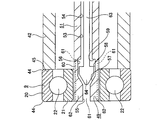
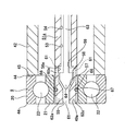
- the schematic diagram which shows the process of inserting a rolling bearing into a worm storage part using the bearing insertion apparatus which shows the 1st example of embodiment of this invention.
- the partial cutting side view which shows an example of the steering device for motor vehicles incorporating the electric power steering device.
- IV-IV sectional drawing of FIG. Sectional drawing which shows the assembly process of a worm reduction gear part.
- Sectional drawing which shows the assembly process of a worm reduction gear part.
- the bearing insertion device 19 of this example is a bearing in which a tip side bearing 9 as a work is formed in a worm storage portion 14 for storing a worm 6 (see FIGS. 5, 6A, 6B, and 6C) that constitutes a worm reduction gear. It is a device for automatically inserting into the insertion section 16.
- the front end side bearing 9 includes an annular outer ring 20 having an outer ring raceway on an inner peripheral surface, an annular inner ring 21 having an inner ring raceway on an outer peripheral surface, and these outer ring raceway and inner ring raceway.
- annular outer ring 20 having an outer ring raceway on an inner peripheral surface
- annular inner ring 21 having an inner ring raceway on an outer peripheral surface
- these outer ring raceway and inner ring raceway Is a single row deep groove type radial ball bearing having a plurality of balls 22, 22 provided so as to be able to roll between them, and the tip of the worm 6 can be rotated inside the worm storage portion 14. It is for support.
- chamfered portions 44, 44 each having an arcuate cross section are formed between the both side surfaces in the axial direction of the outer ring 20 and the outer peripheral surface.
- the worm storage unit 14 is provided in a part of the housing 3 for storing the worm speed reducer constituting the electric power steering apparatus, and is made of aluminum alloy, synthetic resin, or the like. Further, the worm storage portion 14 is formed in a substantially bottomed cylindrical shape, and its internal space is an internal space of the worm wheel storage portion 17 for storing the worm wheel 4 (see FIGS. 5, 6A, 6B, and 6C). Communicating with Further, an abutting portion (step surface) 15 that exists on a virtual plane orthogonal to the central axis of the worm storage portion 14 is formed at the back of the inner peripheral surface of the worm storage portion 14 having such a configuration. ing.
- a bearing insertion portion 16 having a single cylindrical surface shape is formed in a portion adjacent to the opening side of the abutting portion 15 in the inner portion of the inner peripheral surface of the worm storage portion 14.
- the inner diameter dimension of the bearing insertion portion 16 is set to be approximately 10 ⁇ m larger than the outer diameter dimension of the outer ring 20 of the front end side bearing 9.
- the distance (horizontal direction distance) L14 from the motor side end face 23 located at the opening of the worm storage part 14 to the bearing insertion part 16 is about 200 mm.
- the bearing insertion device 19 includes a base 24, a moving base 25, an apparatus main body 26, a guide mechanism 27, and an NC device (not shown). Of these, the base 24 is placed horizontally on the floor of the factory.
- the base 24 is provided with a drive mechanism 28 provided with a drive motor and a ball screw device (not shown), and the moving base 25 provided on the base 24 is used as a movement command from the NC device. Based on this, it is moved in the horizontal Z-axis direction (the left-right direction in FIG.
- the movable table 25 includes a first mounting plate portion 29 extending in the horizontal direction and a second mounting plate portion 30 standing in the vertical direction.
- FIG. 1 shows a state before the moving base 25 is moved in the Z-axis direction (a state located at the origin). Further, a mounting base 31 is placed on the floor surface in front of the moving base 25 in the moving direction (left side in FIG. 1), and the housing 3 is placed on the mounting base 31 so as to open the worm storage section 14. It is fixed in a state where the portion is directed to the bearing insertion device 19 side.
- the apparatus main body 26 is supported by a movable table 25 as described above via a guide mechanism 27 so as to freely move in a predetermined direction.
- the guide mechanism 27 includes two horizontal linear guides 32 a and 32 b and one vertical linear guide 33.
- one of the horizontal linear guide 32a and the vertical linear guide 33 is combined with each other to form a cross shape, and the front surface of the second mounting plate portion 30 constituting the movable table 25 (FIG. 1).
- the other horizontal linear guide 32b is provided via an air cylinder 34 at a portion between the upper surface of the first mounting plate portion 29 constituting the moving base 25 and the lower surface of the apparatus main body 26 (cylinder main body 52). ing.
- Both horizontal linear guides 32a and 32b allow the apparatus main body 26 to move freely in the horizontal X-axis direction (front and back directions in FIG. 1) perpendicular to the Z-axis direction with respect to the moving base 25. is there.
- the vertical direction linear guide 33 the apparatus main body 26 moves freely with respect to the moving base 25 in the Y-axis direction (vertical direction in FIG. 1) perpendicular to the Z-axis direction and the X-axis direction. Is allowed.
- One horizontal linear guide 32a and one vertical linear guide 33 which are combined to form a cross shape include a pair of guide rails 36a and 36b, a slider 37a, and a plurality of rolling elements (not shown). ing.
- the slider 37a is straddled between the guide rails 36a and 36b arranged orthogonal to each other through a plurality of rolling elements so as to be relatively movable along the longitudinal direction of the guide rails 36a and 36b. is doing.
- the other horizontal linear guide 32b includes a guide rail 36c, a slider 37b, and a plurality of rolling elements (not shown).
- the slider 37b is inserted into the guide rail 36c via the plurality of rolling elements.
- the guide rail 36c is straddled so as to be relatively movable along the longitudinal direction.
- a structure is provided in which a separate cylinder device is provided to stop the movement of the sliders 37a and 37b at predetermined positions such as the longitudinal center positions of the guide rails 36a, 36b, and 36c. It can also be adopted.
- a floating joint that may be used in combination with an air cylinder device in a machine tool or the like can be used.
- the base end portion of the floating joint is supported and fixed to the slider 37a, and the tip end portion is fixed to the apparatus main body 26 (cylinder main body 52).
- this apparatus main body 26 can be supported with respect to the slider 37a so that slight displacement (for example, about 1 mm displacement) of the X-axis direction is possible.
- the air cylinder 34 is provided to prevent the apparatus main body 26 permitted to move in the Y-axis direction with respect to the moving table 25 by the vertical linear guide 33 from moving downward due to gravity or the like.
- the air cylinder 34 includes a piston 38 and a cylinder main body 39 fitted with the piston 38.
- the piston 38 applies a force directed upward to the apparatus main body 26.
- the apparatus main body 26 is floatingly supported from below at a predetermined height position while allowing a predetermined amount of movement in the Y-axis direction.
- the air cylinder 34 applies a force having a magnitude commensurate with the gravity acting on the apparatus main body 26 and the front-end bearing 9 supported by the apparatus main body 26. Therefore, when an external force directed downward or upward acts on the apparatus main body 26 during the insertion operation, the apparatus main body 26 is allowed to move downward or upward within a range in which the piston 38 can be displaced.
- the apparatus main body 26 includes an outer ring support mechanism 40 and an inner ring clamp mechanism 41.
- the outer ring support mechanism 40 includes an outer ring support cylinder portion 42 and a cylinder portion drive device 43 that is a hydraulic cylinder device or an air cylinder device.
- the outer ring support cylinder portion 42 is a hollow cylinder and is formed in an elongated shape, and has a distal end surface 45 on one side surface (the right side surface in FIGS. 1, 2A and 2B) of the outer ring 20 constituting the distal end side bearing 9.
- the overall length L42 of the outer ring support cylinder portion 42 is larger than the distance L14 from the motor side end face 23 to the bearing insertion portion 16 with respect to the worm storage portion 14 (L42> L14). Further, in the case of the illustrated structure, the outer diameter of the outer ring 20 is made constant over the entire length of the outer ring support cylinder portion 42 excluding the base end portion where the mounting flange 46 to be described later is fitted. It is slightly smaller than. However, depending on the shape of the inner surface of the worm storage portion, a tapered portion may be provided at the tip of the outer ring support cylinder portion so that the outer diameter size of the intermediate portion is larger than the outer diameter size of the outer ring 20.
- the front end surface 45 of the outer ring support cylinder part 42 is formed in an annular shape that exists on a virtual plane orthogonal to the central axis of the outer ring support cylinder part 42. Further, the outer diameter dimension of the front end face 45 is slightly smaller than the outer diameter dimension of the outer ring 20, and the inner diameter dimension of the front end face 45 is the same as or smaller than the inner diameter dimension of the outer ring 20. Although illustration is omitted, the inner diameter dimension of the front end surface 45 can be made smaller than the outer diameter dimension of the inner ring 21.
- An annular mounting flange 46 is externally fitted and fixed to the outer peripheral surface of the base end portion of the outer ring support tube portion 42. And the front-end
- the drive rod 47 has a base end portion fitted in the cylinder body 48, and is supplied with exhaust oil or air into the cylinder body 48 based on a command from the NC device. It is possible to move to.
- the outer ring support cylinder part 42 is guided around a later-described intermediate cylinder part 51 constituting the inner ring clamp mechanism 41 so as to be capable of relative displacement in the Z-axis direction via a sliding bearing (not shown). It is supported.
- the inner ring clamp mechanism 41 includes a clamp body portion 49, a clamp drive device 50 that is a hydraulic cylinder device or an air cylinder device, and an intermediate cylinder portion 51.
- the intermediate cylinder portion 51 is made of a metal such as aluminum alloy or stainless steel, is configured in a substantially cylindrical shape, and is disposed concentrically inside the outer ring support cylinder portion 42. Further, the base end portion (right end portion in FIG. 1) of the intermediate cylinder portion 51 is connected and fixed to a cylinder main body 52 constituting the clamp driving device 50. In this state, the distal end portion (FIG. 1) of the intermediate cylinder portion 51 is provided. The left end portion of the outer ring support cylinder portion 42 protrudes in the Z-axis direction.
- a through hole 53 that penetrates in the Z-axis direction is formed inside the intermediate cylinder portion 51.
- the through-hole 53 is formed in a range extending from the proximal end portion of the intermediate cylinder portion 51 to the portion closer to the distal end, and is formed in a small-diameter hole portion 54 having a constant inner diameter dimension and a distal end portion of the intermediate cylinder portion 51.
- An opening hole 55 having an inner diameter larger than that of the small diameter hole 54 and a storage hole 56 formed between the small diameter hole 54 and the opening hole 55 are provided.
- the storage hole portion 56 is formed in a state of being continuous with the inner peripheral surface of the opening hole portion 55, and is inclined in a direction in which the inner diameter dimension decreases as the opening hole portion 55 is approached.
- a thin portion 60 having a cylindrical surface portion 58 on the inner peripheral surface is formed around the storage hole portion 56.
- the respective base end portions are located at portions where they are aligned with the stepped surface portion 59 in the Z-axis direction, and the respective distal end portions of the intermediate cylinder portion 51 are located.
- Slits 61, 61 opened at the front end edge are formed in the Z-axis direction. And the part which exists between these slits 61 and 61 regarding the circumferential direction among the front end side parts of this intermediate
- the clamp main body portion 49 is configured by a portion (tip portion) protruding from the tip end portion of the outer ring support tube portion 42 among these expansion / contraction portions 62, 62.
- the outer diameter of the clamp body 49 is slightly smaller than the inner diameter of the inner ring 21 when the clamp body 49 is not driven (the inner ring 21 is not clamped).
- the clamp driving device 50 is a hydraulic cylinder device or an air cylinder device, and includes a piston rod 63 disposed inside the intermediate cylinder portion 51 and a cylinder body 52 in which a proximal end portion of the piston rod 63 is fitted. Yes.
- the cylinder body 52 is supported to the second mounting plate 30 by one horizontal linear guide 32a and a vertical linear guide 33 so as to allow relative displacement in the X-axis direction and the Y-axis direction. .
- the cylinder body 52 is supported relative to the first mounting plate portion 29 by the other horizontal linear guide 32b so as to be capable of relative displacement in the X-axis direction, and is positioned in the Y-axis direction by the air cylinder 34. Floating is supported from below while allowing a certain amount of movement.
- Such a clamp driving device 50 can move the piston rod 63 in the Z-axis direction by supplying or discharging pressure oil or air into the cylinder body 52 based on the command of the command from the NC device.
- a cam portion 64 having a tip portion of a partially conical column whose outer diameter is reduced toward the tip side.
- the cam portion 64 is disposed in a storage hole portion 56 formed on the inner side of the intermediate tube portion 51, and an outer peripheral surface of the tip end portion is opposed to the inclined surface portion 57.
- the cam portion 64 is moved forward in the Z-axis direction with the clamp main body portion 49 being inserted inside the inner ring 21.
- the outer peripheral surface of the distal end portion of the cam portion 64 is pressed against the inclined surface portion 57, and each of the expansion / contraction portions 62, 62 is expanded outward in the radial direction from the base end portion of each of the expansion / contraction portions 62, 62 (slit 61 , 61 to increase the width dimension in the circumferential direction).
- the inner ring 21 is gripped (clamped) with a predetermined holding force by pressing the outer peripheral surface of each of the expansion / contraction portions 62, 62 against the inner peripheral surface of the inner ring 21.
- the cam portion 64 (piston rod 63) is moved backward in the Z-axis direction inside the storage hole portion 56.
- each expansion-contraction part 62 and 62 is elastically restored, and the retention strength with respect to the inner ring
- each expansion-contraction part 62 and 62 is functioned as a leaf
- the operation of inserting the front end side bearing 9 into the bearing insertion portion 16 formed in the inner peripheral surface of the worm storage portion 14 by the bearing insertion device 19 of this example having the above-described configuration is as follows. To do. First, the front end side bearing 9 is automatically supplied by a bearing supply device (not shown) and set to the bearing insertion device 19. That is, the clamp main body 49 (the front end portions of the expansion / contraction portions 62 and 62) is inserted inside the inner ring 21, and one side surface of the outer ring 20 is brought into contact with the front end surface 45 of the outer ring support cylinder portion 42.
- the bearing insertion device 19 of this example supplies / discharges pressurized oil or air to / from the cylinder body 52 constituting the inner ring clamp mechanism 41 based on a command from the NC device, and moves the piston rod 63 to Z Move forward in the axial direction.
- each expansion-contraction part 62 and 62 is expanded radially outward using the outer peripheral surface of the front-end
- the center axis of the tip end side bearing 9 is in the vicinity of the center axis of the bearing insertion portion 16 (at least the tolerance) with the tip end bearing 9 clamped by the clamp body 49.
- Positioning in the Y-axis direction of the apparatus main body 26 is performed in advance using the air cylinder 34 or the like, and positioning in the X-axis direction is performed in advance so as to be positioned within a range of a certain degree of deviation.
- the moving base 25 provided on the base 24 and the apparatus main body 26 supported by the moving base 25 are moved forward (translated) in the Z-axis direction.
- the front end side bearing 9 clamped by the clamp main body portion 49 is inserted into the inside of the worm storage portion 14 from the opening side.
- the outer peripheral surface (mainly chamfered portion 44) of the outer ring 20 constituting the distal end side bearing 9 is the inner peripheral surface of the worm storage portion 14 (for example, the inclined surface 65 formed on the opening side of the bearing insertion portion 16).
- the tip side bearing 9 When the contact is made, the tip side bearing 9 is automatically moved in the radial direction (X-axis direction, Y-axis direction) (automatically based on the pressing force in the Z-axis direction), and the insertion in the Z-axis direction is continued. To do.
- the fact that the other side surface (the left side surface in FIGS. 1, 2A and 2B) of the outer ring 20 constituting the front end side bearing 9 is in contact with the abutting portion 15 is the magnitude of the rotational torque of the drive motor that drives the movable table 25. Insertion is continued until it is detected, and when it is detected, the driving of the movable table 25 is stopped.
- the NC device monitors the magnitude of the rotational torque of the drive motor that drives the moving table 25 and also monitors the position of the moving table 25 (position in the Z-axis direction). As a result, if the rotational torque increases before the tip end bearing 9 reaches the insertion completion position (the amount of movement in the Z-axis direction) determined in advance (for example, about 2 mm or more), an abnormality has occurred. Judgment is made and the insertion operation is stopped.
- the position where it is determined that an abnormality has occurred when the rotational torque increases is not limited to a position 2 mm or more before the insertion completion position, and can be set as appropriate.
- the front end side bearing 9 can be automatically inserted into the bearing insertion portion 16 formed at the back of the worm storage portion 14. That is, in the case of the bearing insertion device 19 of the present example, the insertion operation of the front end side bearing 9 is performed in a state where the front end surface 45 of the outer ring support cylinder portion 42 is in contact with one side surface of the outer ring 20. It can be detected from the magnitude of the rotational torque of the drive motor that drives 25 that the front end side bearing 9 has come into contact with the abutting portion 15. For this reason, as in this example, even when the insertion distance of the tip side bearing 9 is long, it is possible to prevent the amount of insertion from being insufficient, and to insert the tip side bearing 9 into the bearing insertion portion 16 reliably. Can do.
- the apparatus main body 26 can be freely moved with respect to the moving table 25 in the X-axis direction and the Y-axis direction by the horizontal linear guides 32 a and 32 b and the vertical linear guide 33. For this reason, even when the center axis of the bearing insertion portion 16 and the center axis of the front end side bearing 9 do not coincide with each other due to tolerances existing in the bearing insertion portion 16 during the insertion operation as described above.
- the apparatus main body 26 is moved in the X-axis direction and the Y-axis direction.
- the tip end bearing 9 can be moved (aligned) in the radial direction. Therefore, according to the bearing insertion device 19 of this example, like the bearing insertion part 16 formed in the worm storage part 14, the margin in the radial direction between the tip end side bearing 9 is small, and the dimensional tolerance is reduced.
- the front end side bearing 9 is automatically moved appropriately in the radial direction so that the central axis of the front end side bearing 9 automatically matches the central axis of the bearing insertion portion 16 or Can be brought close (can be aligned).
- the bearing insertion device 19 of this example it is considered difficult to automatically insert the bearing insertion portion 16 formed in the worm storage portion 14 for storing the worm 6 constituting the worm speed reducer.
- the rolling bearing can be automatically inserted for the bearing insertion portion that has been provided.
- the expansion / contraction portions 62a, 62a are easily deformed inward in the radial direction by the elastic force directed inward in the radial direction exerted by the O-ring 67. Further, by causing the outer peripheral edge of the O-ring 67 to protrude radially outward from the circumferential grooves 66, 66, the outer peripheral surface of the O-ring 67 is brought into contact with the inner peripheral surface of the inner ring 21, The gripping force of the inner ring 21 is improved.
- Other configurations and operational effects are the same as those of the first example of the embodiment.
- an elastic member can be used in place of the air cylinder as a mechanism for floatingly supporting the apparatus main body with respect to the moving table.
- it can replace with a cylinder apparatus and can utilize an electric motor as each drive device of an outer ring
- a mechanism that converts rotational motion into linear motion such as a feed screw mechanism, may be combined.
- the outer ring support mechanism, the inner ring clamp mechanism, and the guide mechanism are not limited to the structures described in the embodiments, as long as the respective functions can be exhibited, and various structures can be adopted.
Landscapes
- Engineering & Computer Science (AREA)
- Mechanical Engineering (AREA)
- Chemical & Material Sciences (AREA)
- Combustion & Propulsion (AREA)
- Transportation (AREA)
- Mounting Of Bearings Or Others (AREA)
- Automatic Assembly (AREA)
- Power Steering Mechanism (AREA)
- Rolling Contact Bearings (AREA)
Abstract
Selon la présente invention, un montant mobile est disposé sur une base qui est installée sur une surface de sol, le montant mobile étant disposé de manière à être apte à se déplacer dans une direction d'axe Z horizontal qui coïncide avec une direction de mouvement vers un boîtier et s'éloignant de ce dernier. Un dispositif de corps principal, qui est destiné à soutenir, au niveau d'une partie de pointe de ce dernier, un palier de roulement, est soutenu par un mécanisme de guidage de manière à être apte à se déplacer, par rapport au montant mobile, dans une direction d'axe X horizontal qui est orthogonale à la direction d'axe Z et dans une direction d'axe Y vertical qui est orthogonale à la direction d'axe Z et à la direction d'axe X.
Priority Applications (3)
| Application Number | Priority Date | Filing Date | Title |
|---|---|---|---|
| EP16758919.1A EP3266562B1 (fr) | 2015-03-02 | 2016-03-01 | Dispositif d'insertion de palier |
| US15/555,420 US10118262B2 (en) | 2015-03-02 | 2016-03-01 | Bearing insertion device |
| CN201680013477.0A CN107438499B (zh) | 2015-03-02 | 2016-03-01 | 轴承插入装置 |
Applications Claiming Priority (2)
| Application Number | Priority Date | Filing Date | Title |
|---|---|---|---|
| JP2015039927A JP6172183B2 (ja) | 2015-03-02 | 2015-03-02 | 軸受挿入装置 |
| JP2015-039927 | 2015-03-02 |
Publications (1)
| Publication Number | Publication Date |
|---|---|
| WO2016140226A1 true WO2016140226A1 (fr) | 2016-09-09 |
Family
ID=56845838
Family Applications (1)
| Application Number | Title | Priority Date | Filing Date |
|---|---|---|---|
| PCT/JP2016/056278 Ceased WO2016140226A1 (fr) | 2015-03-02 | 2016-03-01 | Dispositif d'insertion de palier |
Country Status (5)
| Country | Link |
|---|---|
| US (1) | US10118262B2 (fr) |
| EP (1) | EP3266562B1 (fr) |
| JP (1) | JP6172183B2 (fr) |
| CN (1) | CN107438499B (fr) |
| WO (1) | WO2016140226A1 (fr) |
Families Citing this family (12)
| Publication number | Priority date | Publication date | Assignee | Title |
|---|---|---|---|---|
| JP6172183B2 (ja) * | 2015-03-02 | 2017-08-02 | 日本精工株式会社 | 軸受挿入装置 |
| CN108127369B (zh) * | 2017-12-01 | 2019-10-29 | 齐齐哈尔四达铁路设备有限责任公司 | 铁路车辆智能轮对压装立体库生产线 |
| CN108555553A (zh) * | 2017-12-14 | 2018-09-21 | 宁波水表股份有限公司 | 一种超声波水表反射片安装系统 |
| CN109099069B (zh) * | 2018-09-30 | 2020-01-31 | 芜湖安普机器人产业技术研究院有限公司 | 用于机器人自动装配轴承的组装台及其使用方法 |
| KR102157190B1 (ko) * | 2020-07-29 | 2020-09-17 | 에이스이엔지 주식회사 | 차량용 배터리 인디케이터 조립장치 |
| CN114515946B (zh) * | 2022-02-21 | 2023-04-11 | 东风柳州汽车有限公司 | 一种蜗杆压装系统 |
| CN114845540B (zh) * | 2022-05-16 | 2023-09-29 | 广东安达智能装备股份有限公司 | Z轴快换式组装机 |
| CN115143194B (zh) * | 2022-07-12 | 2024-01-12 | 山东利腾轴承制造有限公司 | 一种自润滑关节轴承调整装置 |
| CN117506407B (zh) * | 2022-07-28 | 2026-04-28 | 中冶宝钢技术服务有限公司 | 一种平整机用轧辊拆装装置及方法 |
| CN116060911B (zh) * | 2023-03-02 | 2025-07-25 | 灵璧县水利水电建筑安装工程有限公司 | 一种管道支撑装置 |
| WO2025115866A1 (fr) * | 2023-12-01 | 2025-06-05 | Smc株式会社 | Unité de conformité |
| CN119609638B (zh) * | 2025-02-17 | 2025-12-02 | 山东海纳智能装备科技股份有限公司 | 矿用减速型永磁变频调速一体机组装设备 |
Citations (2)
| Publication number | Priority date | Publication date | Assignee | Title |
|---|---|---|---|---|
| JPS61199330U (fr) * | 1985-05-31 | 1986-12-13 | ||
| JPH01127236A (ja) * | 1987-11-09 | 1989-05-19 | Hitachi Ltd | 軸受の圧入方法、及び、軸受の圧入装置 |
Family Cites Families (16)
| Publication number | Priority date | Publication date | Assignee | Title |
|---|---|---|---|---|
| US3709622A (en) * | 1970-11-12 | 1973-01-09 | G Morse | Drill press attachment assembly |
| US4571841A (en) * | 1984-03-20 | 1986-02-25 | General Electric Company | Tool pre-gauging device |
| US4949444A (en) * | 1987-04-17 | 1990-08-21 | Yamazaki Mazak Corporation | Machine tool machining method |
| US5097575A (en) * | 1987-04-17 | 1992-03-24 | Yamazaki Mazak Corporation | Complex machining machine tool |
| JPH0620681B2 (ja) * | 1989-04-17 | 1994-03-23 | 本田技研工業株式会社 | パーツ圧入装置 |
| US5067231A (en) | 1989-04-17 | 1991-11-26 | Honda Giken Kogyo Kabushiki Kaisha | System for press-fitting parts into workpiece |
| JPH04256527A (ja) * | 1991-01-31 | 1992-09-11 | Nichiden Mach Ltd | 精密部品の圧入装置 |
| US5583647A (en) * | 1993-05-05 | 1996-12-10 | Ohio Electronic Engravers, Inc. | Cylinder support apparatus and method for use in an engraver |
| JPH0737542U (ja) | 1993-12-21 | 1995-07-11 | 株式会社安川電機 | 軸受挿入装置 |
| US5537734A (en) * | 1995-01-30 | 1996-07-23 | Western Atlas, Inc. | Press |
| US20060191736A1 (en) | 2003-06-25 | 2006-08-31 | Atsushi Maeda | Electric power steering device |
| JP2005014734A (ja) | 2003-06-25 | 2005-01-20 | Nsk Ltd | 電動パワーステアリング装置 |
| JP2008213667A (ja) | 2007-03-05 | 2008-09-18 | Nsk Ltd | 電動式パワーステアリング装置 |
| JP2011143481A (ja) * | 2010-01-12 | 2011-07-28 | Tokyo Parts Ind Co Ltd | 圧入装置 |
| CN204171913U (zh) * | 2014-08-28 | 2015-02-25 | 芜湖恒隆汽车转向系统有限公司 | 一种用于汽车转向器壳体压装底部轴承的工装 |
| JP6172183B2 (ja) * | 2015-03-02 | 2017-08-02 | 日本精工株式会社 | 軸受挿入装置 |
-
2015
- 2015-03-02 JP JP2015039927A patent/JP6172183B2/ja not_active Expired - Fee Related
-
2016
- 2016-03-01 US US15/555,420 patent/US10118262B2/en active Active
- 2016-03-01 WO PCT/JP2016/056278 patent/WO2016140226A1/fr not_active Ceased
- 2016-03-01 CN CN201680013477.0A patent/CN107438499B/zh not_active Expired - Fee Related
- 2016-03-01 EP EP16758919.1A patent/EP3266562B1/fr not_active Not-in-force
Patent Citations (2)
| Publication number | Priority date | Publication date | Assignee | Title |
|---|---|---|---|---|
| JPS61199330U (fr) * | 1985-05-31 | 1986-12-13 | ||
| JPH01127236A (ja) * | 1987-11-09 | 1989-05-19 | Hitachi Ltd | 軸受の圧入方法、及び、軸受の圧入装置 |
Also Published As
| Publication number | Publication date |
|---|---|
| CN107438499B (zh) | 2019-08-02 |
| JP6172183B2 (ja) | 2017-08-02 |
| US10118262B2 (en) | 2018-11-06 |
| US20180036844A1 (en) | 2018-02-08 |
| CN107438499A (zh) | 2017-12-05 |
| EP3266562A4 (fr) | 2018-02-28 |
| JP2016159393A (ja) | 2016-09-05 |
| EP3266562B1 (fr) | 2019-02-13 |
| EP3266562A1 (fr) | 2018-01-10 |
Similar Documents
| Publication | Publication Date | Title |
|---|---|---|
| JP6172183B2 (ja) | 軸受挿入装置 | |
| JP4644072B2 (ja) | 拡管工具 | |
| JP5602218B2 (ja) | 中ぐり工具および工作機械 | |
| CN201931307U (zh) | 薄板类零件外圆车夹具 | |
| JP2017510771A (ja) | リニアアクチュエータアセンブリ | |
| US20110303044A1 (en) | Automatic clearance compensation device for support yoke of rack-pinion type steering apparatus | |
| JP5862734B1 (ja) | 直線駆動装置 | |
| JP2005138216A (ja) | インデックステーブル | |
| KR20180130288A (ko) | 스핀들 장치 및 그의 작동방법 | |
| CN107848014A (zh) | 轴承单元的制造方法以及制造装置 | |
| CN106461041A (zh) | 动力转向装置以及动力转向装置用滚珠丝杠的制造方法 | |
| TWI400393B (zh) | Locating pins | |
| CN101524816B (zh) | 工件的支承装置及旋转分度机 | |
| JP4668160B2 (ja) | 軸受ユニット及び該軸受ユニットを備えた工作機械の主軸装置 | |
| KR101536180B1 (ko) | 샤프트 복합가공기 | |
| JP6767779B2 (ja) | チャック装置及びワークチャック方法 | |
| JP2017159394A (ja) | 回転テーブル装置、及び当該装置を備えた工作機械 | |
| US20200291989A1 (en) | Hydrostatic bearing spindle device and machine tool including the same | |
| EP3279509A1 (fr) | Réducteur à engrenages de type rouleau à friction | |
| JP6519664B2 (ja) | 止め輪、回転機械、及び止め輪の装着方法 | |
| KR102736645B1 (ko) | 공작기계의 주축 고정장치 | |
| JPH1113755A (ja) | 予圧を付与された転がり軸受装置 | |
| JP2019018258A (ja) | ハブベアリング圧入用工具 | |
| WO2017064742A1 (fr) | Dispositif d'entraînement linéaire | |
| KR101471045B1 (ko) | 차량용 프론트너클 가공방법 |
Legal Events
| Date | Code | Title | Description |
|---|---|---|---|
| 121 | Ep: the epo has been informed by wipo that ep was designated in this application |
Ref document number: 16758919 Country of ref document: EP Kind code of ref document: A1 |
|
| WWE | Wipo information: entry into national phase |
Ref document number: 15555420 Country of ref document: US |
|
| NENP | Non-entry into the national phase |
Ref country code: DE |
|
| REEP | Request for entry into the european phase |
Ref document number: 2016758919 Country of ref document: EP |