WO2016142965A1 - Dispositif de traitement vidéo, procédé de traitement vidéo et support de stockage pour le stockage du programme de traitement vidéo - Google Patents
Dispositif de traitement vidéo, procédé de traitement vidéo et support de stockage pour le stockage du programme de traitement vidéo Download PDFInfo
- Publication number
- WO2016142965A1 WO2016142965A1 PCT/JP2015/001307 JP2015001307W WO2016142965A1 WO 2016142965 A1 WO2016142965 A1 WO 2016142965A1 JP 2015001307 W JP2015001307 W JP 2015001307W WO 2016142965 A1 WO2016142965 A1 WO 2016142965A1
- Authority
- WO
- WIPO (PCT)
- Prior art keywords
- motion
- motion vector
- video processing
- video
- difference
- Prior art date
- Legal status (The legal status is an assumption and is not a legal conclusion. Google has not performed a legal analysis and makes no representation as to the accuracy of the status listed.)
- Ceased
Links
Images




Classifications
-
- G—PHYSICS
- G01—MEASURING; TESTING
- G01N—INVESTIGATING OR ANALYSING MATERIALS BY DETERMINING THEIR CHEMICAL OR PHYSICAL PROPERTIES
- G01N21/00—Investigating or analysing materials by the use of optical means, i.e. using sub-millimetre waves, infrared, visible or ultraviolet light
- G01N21/84—Systems specially adapted for particular applications
- G01N21/88—Investigating the presence of flaws or contamination
Definitions
- the present invention relates to a technique for processing video.
- Patent Literature 1 discloses a method for detecting cracks in a structure constructed using concrete or the like.
- the crack detection system of Patent Document 1 forms an element that is a set of at least three sample points from a plurality of sample points existing on the surface of a structure where a crack is detected.
- the sample point is a point whose position is determined by, for example, the structure or pattern of the surface of the structure.
- the crack detection system detects the position of a sample point in an image obtained by photographing the surface of the structure.
- the crack detection system determines the magnitude of deformation of the structure based on the magnitude of the detected change in the position of the sample point.
- One of the objects of the present invention is to provide an image processing apparatus capable of improving the accuracy of detecting portions that move differently in an image.
- the video processing method calculates a magnitude of a difference between a set of motion vector transitions of a video, and sets a position of a set of motion vector transitions representing different motions in the video to the magnitude of the difference. Extract based on.
- a recording medium provides a computer, a difference calculation unit that calculates the magnitude of a difference between sets of motion vector transitions of a video, and a position of a set of motion vector transitions that represent different motions in the video.
- a video processing program to be operated as motion extraction means for extracting based on the magnitude of the difference is stored.
- the present invention can also be realized by a video processing program stored in the recording medium.
- the present invention has an effect that it is possible to improve the accuracy of detecting a portion that moves differently in an image.
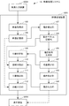
- FIG. 1 is a block diagram showing an example of the configuration of a video processing system 1 according to the first embodiment of the present invention.
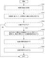
- FIG. 2 is a flowchart showing an example of the operation of the video processing system 1 according to the first embodiment of the present invention.
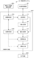
- FIG. 3 is a block diagram showing an example of the configuration of a video processing system 1A according to the second embodiment of the present invention.
- FIG. 4 is a flowchart showing the operation of the video processing system 1A according to the second embodiment of the present invention.
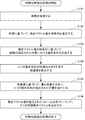
- FIG. 5 is a flowchart showing an example of the operation in the feature position extraction process of the video processing system 1A according to the second embodiment of the present invention.
- FIG. 1 is a block diagram showing an example of the configuration of a video processing system 1 according to the first embodiment of the present invention.
- FIG. 2 is a flowchart showing an example of the operation of the video processing system 1 according to the first embodiment of the present invention.
- FIG. 3 is a block diagram showing an example of the configuration of a
- FIG. 6 is a block diagram showing an example of the configuration of a video processing system 1B according to a modification of the second embodiment of the present invention.
- FIG. 7 is a block diagram showing a configuration of a video processing apparatus 100C according to the third embodiment of the present invention.
- FIG. 8 is a diagram illustrating an example of a hardware configuration of a computer 1000 that can realize the video processing device and the separation detection device according to each embodiment of the present invention.
- the video processing apparatus 100 includes a motion sequence generation unit 101, a difference calculation unit 102, a motion extraction unit 103, a motion output unit 104, a video acquisition unit 105, a video storage unit 106, a motion estimation unit 107, and a motion A vector storage unit 108.
- a still image (corresponding to a frame of a video) included in a video that is continuous still image data is also referred to as a “frame”.
- operating video data for example, inputting video data
- operating video for example, inputting video
- the video input device 200 may be, for example, a shooting device that takes a picture of an object and transmits a video obtained by shooting to the video processing device 100.
- the video input device 200 may be a video server device that stores a video of an object photographed by the photographing device and transmits the stored video to the video processing device 100.
- the video acquisition unit 105 receives video from the video input device 200.
- the video acquisition unit 105 stores the received video in the video storage unit 106.
- the video storage unit 106 stores the video input from the video input device 200.
- the motion estimation unit 107 estimates motion vectors at a plurality of positions determined in advance for a plurality of frames included in the video.
- the motion vector represents the direction and magnitude of movement of the region including the position where the motion vector is estimated.
- the motion vector is a value representing the motion in the plane in the coordinate system set for the frame.
- the motion vector is represented by a vector having two elements, for example.
- the position where the estimated motion vector represents the direction and magnitude of movement is also expressed as “position of motion vector”, “position where motion vector is estimated”, or the like.
- the motion estimation unit 107 estimates a motion vector by comparing a frame for estimating a motion vector with a reference frame.
- the reference frame is a frame before (for example, immediately before) a frame in which a motion vector is estimated in the video.
- various existing methods such as a method using correlation based on pixel values and a method using phase correlation can be applied.
- the position where the motion vector is estimated is, for example, a position at a predetermined interval included in an area where the motion vector can be estimated in the method in which the motion estimation unit 107 estimates the motion vector.
- the position of the predetermined interval is, for example, the position of a lattice point of any kind of planar lattice set on the frame surface.
- the position where the motion vector is estimated may be, for example, the position of each pixel included in the region where the motion vector can be estimated in the method in which the motion estimation unit 107 estimates the motion vector.
- the motion estimation unit 107 associates the estimated motion vector with the position where the motion vector is estimated.
- the motion estimation unit 107 stores the motion vector associated with the position in the motion vector storage unit 108 for each frame in which the motion vector is estimated.
- the position associated with the motion vector is, for example, the coordinates of the place where the motion vector is estimated.
- a set of motion vectors estimated at a plurality of positions in one frame is also referred to as a “motion vector field”.
- the motion estimation unit 107 stores a motion vector field in the motion vector storage unit 108 for each frame, for example.
- the motion vector storage unit 108 stores, for each frame in which the motion vector is estimated, for example, a motion vector field that is a set of motion vectors associated with the estimated position.
- the motion sequence generation unit 101 generates a motion sequence that is a set of motion vectors estimated at the same position based on the motion vector field for each frame in which the motion vector is estimated, which is stored in the motion vector storage unit 108. Generate.
- the motion vectors included in the motion sequence may be arranged according to the order in the video of the frame in which the motion vector is estimated. A frame number may be associated with each motion vector included in the motion sequence.
- the motion sequence is also referred to as “motion vector transition” or “motion vector time series”.
- f represents a frame number. If the number of frames in which motion vectors are estimated in the video is F, f is an integer from 1 to F. Further, m is a number representing a place where a motion vector is estimated. When the number of positions where motion vectors are estimated is M, m is an integer of 1 to M.
- MV (T f , x m , y m ) represents a motion vector estimated at a position where the coordinate is (x m , y m ) of the frame whose time value is T f. .
- the coordinates (x m , y m ) are the coordinates of the mth position where the motion vector is estimated.
- Equation 2 represents an example of a motion sequence.
- P m shown in Equation 2 is a set of motion vectors (that is, m-th) estimated at the m-th position in each of the first to F-th frames (that is, frames in which motion vectors are estimated in the video). Motion series).
- the motion sequence generation unit 101 generates a motion sequence P m for each m from 1 to M.
- the motion extraction unit 103 indicates the position where the motion vector is estimated for each of the two motion sequences, which indicates that the difference value, which is a value indicating the degree of difference between the motion sequences, is the most different. Extract from multiple fixed positions. “Fixed position” indicates that the position is the same in all frames of the video. The position is represented by coordinates. The plurality of fixed positions may be designated in advance. In each embodiment of the present invention, as described above, the difference value, which is a value indicating the degree of difference between motion sequences, is also referred to as “first difference value”.
- Equation 3 represents an example of a difference value that is a value representing the degree of difference between motion sequences calculated by the difference calculation unit 102.
- the equation shown in Equation 3 is a difference value representing the degree of difference between the motion sequence P u and the motion sequence P v represented by the L1 norm defined for the motion sequence (ie, a difference based on the L1 norm). Value).
- the difference value shown in Equation 3 is the sum of the magnitudes of the differences between the two motion vectors estimated at the u-th position and the v-th position in the same frame for the first to Fth frames. .
- the magnitude of the difference between two motion vectors estimated at the u-th position and the v-th position in the same frame is a difference value indicating the degree of difference between the motion vectors (that is, , The second difference value described above).
- f represents a frame number
- u and v represent position numbers in the plurality of fixed positions described above.
- Equation 4 represents two positions that the motion extraction unit 103 extracts using the difference values exemplified in Equation 3. Similar to the equation shown in Equation 3, in the equation shown in Equation 4, u and v represent position numbers in the plurality of fixed positions described above.
- Equation 4 the combination of m1 and m2, which are position numbers, is an integer of 1 or more and M or less, respectively, and u and v having the largest difference values shown in Equation 3 in different combinations of u and v.
- Numbers m1 and m2 represent the motions of each of the two motion sequences indicating that the difference value, which is a value representing the degree of difference between the motion sequences, extracted by the motion extraction unit 103 is the most different.
- Equation 5 represents another example of a difference value that is a value representing the degree of difference between motion sequences, which is calculated by the difference calculation unit 102.
- the equation shown in Equation 3 is a difference value representing the degree of difference between the motion sequence P u and the motion sequence P v represented by the L2 norm defined for the motion sequence (ie, a difference based on the L2 norm). Value).
- the dissimilarity value shown in Equation 5 is the same for the first to Fth frames of the square of the magnitude of the difference between the two motion vectors estimated at the u th position and the v th position of the same frame. The square root of the sum.
- the magnitude of the difference between two motion vectors estimated at the u-th position and the v-th position in the same frame is a difference value indicating the degree of difference between the motion vectors (that is, , The second difference value described above).
- f represents a frame number
- u and v represent position numbers in the plurality of fixed positions described above.
- Equation 6 represents two positions that the motion extraction unit 103 extracts using the difference values exemplified in Equation 5. Similar to the equation shown in Equation 3, in the equation shown in Equation 6, u and v represent position numbers in the plurality of fixed positions described above.
- Equation 6 the combination of m1 and m2, which are position numbers, is an integer of 1 or more and 1 or less, respectively, and u and v have the largest difference value shown in Equation 5 in the combination of u and v different from each other.
- Numbers m1 and m2 represent the motions of each of the two motion sequences indicating that the difference value, which is a value representing the degree of difference between the motion sequences, extracted by the motion extraction unit 103 is the most different.
- Equation 7 shows that the combination of m1 and m2, which are the position numbers, is an integer of 1 or more and M or less, respectively, and the combination of u and v different from each other has the largest difference value squared shown in Equation 5. This represents a combination of u and v.
- the motion extraction unit 103 may extract two positions according to the equation shown in Equation 7. In that case, when calculating the difference value shown in Formula 5, the calculation of the square root can be omitted.
- the difference calculation unit 102 may calculate a correlation coefficient between two motion vectors estimated at the u-th position and the v-th position of the same frame as the second difference value. Then, the difference calculation unit 102 may calculate the sum of the second difference values for the first to Fth frames as the first difference value.
- the motion output unit 104 outputs the two positions extracted by the motion extraction unit 103 to the output destination device 300.
- the motion output unit 104 may output a motion sequence estimated at these two positions.
- the motion sequence represents a motion vector estimated at the same place in the first to Fth frames, which are frames in which the motion vector field is estimated.
- the motion sequences estimated at the two positions extracted by the motion extraction unit 103 represent the motion vectors estimated at the two locations where the difference between the motion vectors is largest in the first to Fth frames.
- the motion extraction unit 103 includes, in each of the two motion sequences from which the positions are extracted, motion vectors representing the order in which the associated time values are the same. You may extract as a vector.
- the motion output unit 104 may output the above-described two feature motion vectors for each of the plurality of frames in which the motion vector field is estimated to the output destination device 300.
- the motion output unit 104 may output a difference value representing the magnitude of the difference of the motion sequence having the largest difference to the output destination device 300.
- the output destination device 300 may be a display device, for example.
- the output destination device 300 may be a device that performs other operations such as an operation of detecting cracks based on the output of the video processing device 100.
- the output destination device 300 is a device different from the video processing device 100, but the output destination device 300 may be another unit or circuit included in the video processing device 100.
- FIG. 2 is a flowchart showing an example of the operation of the video processing system 1 of the present embodiment.
- the video acquisition unit 105 acquires a video from the video input device 200 (step S101).
- the video acquisition unit 105 stores the acquired video in, for example, the video storage unit 106.
- the motion estimation unit 107 estimates the time series of the motion vector field based on, for example, the video stored in the video storage unit 106 (step S102).
- the motion estimation unit 107 stores a time series of motion vectors in the motion vector storage unit 108.
- the motion sequence generation unit 101 generates motion sequences at a plurality of fixed positions based on the time series of the motion vector field stored in the motion vector storage unit 108 (step S103).
- the difference calculation unit 102 calculates, for each combination of two different positions included in a plurality of fixed positions, a difference value indicating the magnitude of the difference between the motion sequences estimated at the two positions.
- the motion extraction unit 103 extracts a position where the two motion sequences having the largest difference are estimated (step S105).
- the motion extraction unit 103 may further extract the above-described two feature motion vectors for each frame in which the motion vector field is estimated from the video (step S106).
- the motion output unit 104 outputs the extracted two positions to the output destination device 300 (step S107).
- the motion output unit 104 may output, to the output destination device 300, two feature motion vectors for each of the frames in which the motion vector field is estimated.
- the present embodiment described above has a first effect that it is possible to improve the accuracy of detecting portions that move differently in an image. This is because the motion sequence generation unit 101 generates a motion sequence that is a set of motion vectors estimated at a plurality of fixed positions. Then, the motion extraction unit 103 estimates the motion vector of each of the two motion sequences indicating that the first difference value, which is a value indicating the degree of difference between the motion sequences, is the most different. This is because the extracted position is extracted from a plurality of fixed positions.
- the motion vector estimated at the same position may include a motion vector with a large error.
- this embodiment has a second effect that it is possible to improve the accuracy of detecting separation of an object based on an image obtained by photographing the object.
- the reason for this is that if the two positions with the largest difference in motion can be extracted with high accuracy, for example, the regions that perform the same movement are expanded by using the two positions as a starting point. The area of the image of the two parts can be estimated with high accuracy. That is, it is possible to improve the accuracy of detecting separation of an object based on a video image of the object.
- FIG. 3 is a block diagram showing an example of the configuration of the video processing system 1A of the present embodiment.
- the video processing system 1A of the present embodiment includes a video processing device 100A, a video input device 200A, and a display device 300A.
- the video processing device 100A is communicably connected to the video input device 200A and the display device 300A.
- the video processing apparatus 100A of the present embodiment is the same as the video processing apparatus 100 of the first embodiment except for the differences described below.
- the same reference numerals are given to the same components of the video processing device 100A of the present embodiment as those of the video processing device 100 of the first embodiment, and the description thereof is omitted.
- the video processing apparatus 100 ⁇ / b> A includes a separation determination unit 109, an area division unit 110, in addition to the components of the video processing apparatus 100 according to the first embodiment.
- a separation detection unit 111 and a separation output unit 112 are included.
- the difference calculation unit 102 of the present embodiment further transmits a difference value indicating that the difference is the largest among the calculated difference values to the separation determination unit 109.
- the motion output unit 104 transmits the two positions extracted by the motion extraction unit 103 and the motion sequences estimated at each of the two positions to the region dividing unit 110.
- the motion output unit 104 may transmit the above-described two feature motion vectors for each of a plurality of frames in which the motion vector field is estimated, to the region dividing unit 110 instead of the motion sequence. As described above, these feature motion vectors are generated from the estimated motion sequence.
- the region segmentation unit 110 performs a process for each of a plurality of frames in which a motion vector field is estimated from the received motion sequence. It is only necessary to be designed to generate two feature motion vectors.
- the motion output unit 104 calculates the above-described two feature motion vectors for each of the two positions extracted by the motion extraction unit 103 and the plurality of frames from which the motion vector field is estimated.
- the data is transmitted to the area dividing unit 110.
- the separation determination unit 109 determines whether or not the object being photographed in the video is separated into a plurality of parts based on the first difference value that is received from the difference calculation unit 102 and indicates that the difference is the largest. Determine.
- the separation determining unit 109 may compare the received first difference value with, for example, a threshold value experimentally determined in advance. Then, the separation determination unit 109 determines that the object is separated into a plurality of parts when the magnitude of the difference indicated by the received first difference value is greater than the magnitude of the difference indicated by the threshold, and does not In this case, it may be determined that the object is not separated.
- the region dividing unit 110 classifies each motion vector of the motion vector field according to the proximity of each of the two feature vectors included in the motion vector field, and thereby the frame in which the vector field is estimated. Is divided into two regions.
- the area dividing unit 110 may perform area division as follows, for example.
- the area dividing unit 110 first calculates the magnitude of the difference between the motion vector included in the motion vector field and each of the two motion vectors.
- the area dividing unit 110 classifies the motion vector into a group of feature motion vectors having a smaller difference.
- the area dividing unit 110 classifies each motion vector included in the motion vector field into one of two feature motion vector groups.
- the area dividing unit 110 connects adjacent peripheral areas among the peripheral areas of the motion vectors included in the same group at the position where the motion vector is estimated (hereinafter, referred to as the peripheral area of the motion vector).
- the peripheral area may be an area obtained by dividing a frame so that peripheral areas of different motion vectors do not overlap.
- the region dividing unit 110 performs one concatenation for one group of motion vectors in a frame by using various existing region shaping methods such as smoothing the boundary line of the concatenated region and removing the concatenated region whose area is a predetermined value or less.
- the connected area is shaped so that it becomes an area.
- the area dividing unit 110 may perform area division as follows, for example. First, for each of the two feature motion vectors, the region dividing unit 110 sets a peripheral region of the feature vector as a connected region of the feature vector group. Then, the region dividing unit 110 calculates the magnitude of the difference between the motion vector in which the peripheral region is adjacent to the connected region of the group of feature motion vectors and the feature motion vector. When the calculated magnitude of the difference is smaller than a predetermined threshold, the region dividing unit 110 connects the peripheral region of the motion vector to the connected region of the feature motion vector group.
- the region dividing unit 110 is configured to detect motion vectors until a motion vector whose difference from the feature motion vector is smaller than a predetermined value does not exist in the motion vector adjacent to the peripheral region in the connected region of the group of feature motion vectors.
- the connection between the peripheral area and the connection area is repeated.
- the area dividing unit 110 may perform shaping of the connected area such as smoothing the boundary line of the connected area.
- the region dividing unit 110 may generate a connected region for each of the two feature motion vectors by a method other than the method described above.
- One connected area generated as described above includes a place where one feature motion vector is estimated, and the other connected area includes a place where the other feature motion vector is estimated.
- the connected area includes a place where a plurality of motion vectors are estimated that are classified according to proximity to the feature motion vector including the place estimated in the connected area.
- a motion vector in which the estimated location is included in the connected region is referred to as a motion vector of the connected region.
- Two such connected regions are referred to as two connected regions “different in motion”.
- the magnitude of the difference between the two feature motion vectors estimated in the same frame generated from the motion sequence having the largest difference is the magnitude of the difference between the two motion vectors selected from the motion vectors estimated in that frame. It is expected to be higher in the list. It can be said that the two connected regions generated by the region dividing unit 110 in the frame in which the motion vector field is estimated (that is, extracted from the frame) are connected regions having different motions.
- the region dividing unit 110 may generate two connected regions for each of a plurality of frames in which the motion vector field is estimated.
- the separation detection unit 111 selects a boundary between the two connected regions or a region including the boundary within a predetermined distance from the boundary as the target. You may detect as the area
- the separation detection unit 111 separates, for example, an area within a predetermined distance from the boundary between the two connected regions sandwiched between the two connected regions. You may detect as the area
- the separation detection unit 111 may detect a region where the object is separated from each of the plurality of frames in which the motion vector field is estimated.
- the separation output unit 112 displays the area where the object is separated on the display device 300A for the frame where the area where the object is separated is detected. For example, the separation output unit 112 may superimpose a display indicating a region where the object detected in the frame is separated on a frame where the region where the object is separated is detected. . Then, the separation output unit 112 may output a frame on which a display indicating a region where the object is separated is superimposed on the display device 300A. The separation output unit 112 may display the region where the object is separated on the display device 300A for all frames where the region where the object is separated is detected. The separation output unit 112 is configured to display a location where the object is separated for a frame selected by the user using an input device (not shown) from among the frames where the region where the object is separated is detected. The area may be displayed on the display device 300A.
- FIG. 4 is a flowchart showing the operation of the video processing system 1A of the present embodiment.
- the video processing system 1A performs a feature position extraction process (step S201).
- the video processing system 1A extracts two motion sequences having the largest difference by the feature position extraction process.
- the video processing system 1A further calculates a difference value representing the difference between the two motion sequences having the largest difference by the feature position extraction process.
- the video processing system 1A further extracts a position where the two motion sequences are estimated by the feature position extraction process.
- the extracted motion sequence represents the above-described two feature motion vectors of each frame in which the vector field is estimated. The feature position extraction process will be described later.
- the separation determination unit 109 determines the presence / absence of separation of the object based on the difference value indicating the difference between the two motion sequences having the largest difference (step S202).
- the separation output unit 112 may display on the display device 300A a display indicating that there is no separation in the object. Then, the video processing apparatus 100A ends the operation illustrated in FIG.
- FIG. 5 is a flowchart showing an example of the operation in the feature position extraction process of the video processing system 1A of the present embodiment.
- each step shown in FIG. 5 is the same as the operation of the step given the same reference numeral in the operation of the video processing system 1 of the first embodiment shown in FIG.
- the present embodiment described above has the same effect as the first embodiment.
- the reason is the same as the reason for the effect of the first embodiment.
- FIG. 6 is a block diagram showing an example of the configuration of the video processing system 1B of the present modification.
- a video processing system 1B includes a video processing device 100, a separation detection device 100B, a video input device 200A, and a display device 300A.
- the separation detection device 100B is communicably connected to the video processing device 100, the video input device 200A, and the display device 300A.
- the video processing apparatus 100 according to the present modification is the same as the video processing apparatus 100 according to the first embodiment, except for differences described below.
- the separation detection device 100B corresponds to the video input device 200 and the output destination device 300 in the first embodiment.
- the video processing apparatus 100 of this embodiment transmits the time series of the motion vector field estimated based on the video to the separation detection apparatus 100B.
- the video input device 200A is, for example, a photographing device that photographs an object and outputs an image in which the object is photographed.
- the separation detection apparatus 100B includes a video acquisition unit 105B, a video storage unit 106B, a transmission / reception unit 113, a separation determination unit 109, a region division unit 110, a separation detection unit 111, and a separation output unit 112.
- the video acquisition unit 105B acquires a video from the video input device 200A, and stores the acquired video in the video storage unit 106B.
- the video acquisition unit 105 ⁇ / b> B transmits the acquired video to the video processing device 100 via the transmission / reception unit 113.
- the video acquisition unit 105 ⁇ / b> B may read the video stored in the video storage unit 106 ⁇ / b> B from the video storage unit 106 ⁇ / b> B and transmit the read video to the video processing apparatus 100 via the transmission / reception unit 113.
- the video storage unit 106B stores the video acquired from the video input device 200A.
- the transmission / reception unit 113 transmits the video to the video processing device 100.
- the transmission / reception unit 113 receives from the video processing device 100 a difference value representing the magnitude of the difference between the two motion sequences extracted by the video processing device 100 and having the largest difference.
- the transmission / reception unit 113 receives, from the video processing device 100, the position where the two motion sequences with the greatest difference extracted by the video processing device 100 are estimated.
- the transmission / reception unit 113 further receives, from the video processing device 100, the above-described two feature motion vectors of each of the plurality of frames estimated from the motion vector field generated from the two motion sequences having the largest difference. May be.
- the transmission / reception unit 113 may receive, from the video processing device 100, two motion sequences extracted by the video processing device 100 instead of the feature motion vector with the largest difference.
- the transmission / reception unit 113 further receives a time series of the motion vector field estimated based on the video from the video processing device 100.
- the separation determination unit 109, the region division unit 110, the separation detection unit 111, and the separation output unit 112 of the present embodiment are respectively the separation determination unit 109 and the region division unit 110 of the video processing device 100A of the first embodiment. This is the same as the separation detection unit 111 and the separation output unit 112. However, the separation determination unit 109 receives a difference value indicating the magnitude of the difference between the two motion sequences having the largest difference from the video processing device 100 via the transmission / reception unit 113.
- the area dividing unit 110 receives the time series of the motion vector field estimated based on the video from the video processing device 100 via the transmission / reception unit 113.
- the area dividing unit 110 further receives, from the video processing apparatus 100, positions where two motion sequences having the largest differences are estimated.
- the area dividing unit 110 further receives, from the video processing device 100, the above-described two feature motion vectors of each of a plurality of frames with estimated motion vector fields, generated from the two motion sequences having the largest difference. To do.
- FIG. 4 is a flowchart showing the operation of the video processing system 1B of this modification.
- the operation of the video processing system 1B of the present modification is the same as the operation of the video processing system 1A of the second modification.
- FIG. 5 is a flowchart showing the operation in the feature position extraction process of the video processing system 1B of the present modification.
- the operation in the feature position extraction process of the video processing system 1B of the present modification is the same as the operation in the feature position extraction process of the video processing system 1A of the second modification.
- FIG. 7 is a block diagram showing the configuration of a video processing apparatus 100C according to the third embodiment of the present invention.
- the video processing apparatus 100C including the difference calculation unit 102 and the motion extraction unit 103 illustrated in FIG. 7 represents the above-described minimum configuration.
- the video processing apparatus 100C includes a difference calculation unit 102 that calculates the magnitude of a difference between sets of motion vector transitions of a video, and a position of a set of motion vector transitions that represent different motions in the video. And a motion extracting unit 103 that extracts based on the size.
- the present embodiment described above has the same effect as the first effect of the first embodiment.
- the reason is the same as the reason why the first effect of the first embodiment occurs.
- the video processing apparatus can be realized by a computer and a program for controlling the computer, dedicated hardware, or a combination of the computer and the program for controlling the computer and dedicated hardware.
- the separation detection apparatus 100B according to the modification of the second embodiment of the present invention is also realized by a computer and a program for controlling the computer, dedicated hardware, or a combination of a program for controlling the computer and the computer and dedicated hardware. be able to.
- FIG. 8 is a diagram illustrating an example of a hardware configuration of a computer 1000 that can realize the video processing apparatuses 100, 100A, and 100C and the separation detection apparatus 100B according to the above-described embodiment.
- a computer 1000 includes a processor 1001, a memory 1002, a storage device 1003, and an I / O (Input / Output) interface 1004.
- the computer 1000 can access the recording medium 1005.
- the memory 1002 and the storage device 1003 are storage devices such as a RAM (Random Access Memory) and a hard disk, for example.
- the recording medium 1005 is, for example, a storage device such as a RAM or a hard disk, a ROM (Read Only Memory), or a portable recording medium.
- the storage device 1003 may be the recording medium 1005.
- the processor 1001 can read and write data and programs from and to the memory 1002 and the storage device 1003.
- the processor 1001 can access, for example, the video input device 200 and the output destination device 300, or the video input device 200A and the display device 300A via the I / O interface 1004.
- the processor 1001 can access the recording medium 1005.
- the recording medium 1005 stores a program that causes the computer 1000 to operate as the video processing device 100, the video processing device 100A, the video processing device 100C, or the separation detection device 100B.
- the processor 1001 loads into the memory 1002 a program that causes the computer 1000 to operate as the video processing device 100, the video processing device 100A, the video processing device 100C, or the separation detection device 100B, which is stored in the recording medium 1005.
- the processor 1001 executes the program loaded in the memory 1002
- the computer 1000 operates as the video processing device 100, the video processing device 100A, the video processing device 100C, or the separation detection device 100B.
- the first group includes a motion sequence generation unit 101, a difference calculation unit 102, a motion extraction unit 103, a motion output unit 104, a video acquisition unit 105, and a motion estimation unit 107.
- the first group may further include a separation determination unit 109, a region division unit 110, a separation detection unit 111, and a separation output unit 112.
- the first group may further include a video acquisition unit 105B and a transmission / reception unit 113.
- Each unit of the second group described later can be realized by a memory 1002 included in the computer 1000 and a storage device 1003 such as a hard disk device.
- the second group is the video storage unit 106 and the motion vector storage unit 108.
- the second group may further include a video storage unit 106B.
- some or all of the units included in the first group and the units included in the second group can be realized by a dedicated circuit that realizes the function of each unit.
- a difference calculating means for calculating the magnitude of the difference of the set of motion vector transitions of the video;
- a video processing apparatus comprising: motion extraction means for extracting a position of a set of motion vector transitions representing different motions in the video based on the magnitude of the difference.
- Appendix 3 The video processing apparatus according to appendix 1 or 2, further comprising: motion sequence generation means for generating a transition of the motion vector at a specified coordinate.
- the vector transition is a set of motion vectors estimated at the fixed position of the frame of the video;
- the video processing device according to attachment 3, wherein the difference calculation means calculates the magnitude of the difference between the sets of motion vector transitions based on the difference of the motion vectors in the same frame.
- the motion extraction means extracts a motion vector of the frame at a position of a set of motion vector transitions representing the different motions as a feature vector of the frame;
- the video processing device further includes video segmentation means for classifying the motion vector of the frame according to proximity to the feature vector of the frame to extract a region having different motion from the frame.
- Appendix 6 The video processing apparatus according to appendix 5, further comprising separation detection means for detecting the region extracted from the video where the object is photographed as at least a part of an image of a part separated from the object.
- Appendix 7 The video processing apparatus according to appendix 5 or 6, further comprising: a separation determination unit that determines presence of a region having a different motion based on the magnitude of the difference of the set of motion vector transitions representing the different motion.
- Appendix 10 The video processing method according to appendix 8 or 9, wherein a transition of the motion vector at a specified coordinate is generated.
- the vector transition is a set of motion vectors estimated at the fixed position of the frame of the video;
- the video processing method according to claim 10 wherein the magnitude of the difference between the sets of motion vector transitions is calculated based on the difference of the motion vectors in the same frame.
- Appendix 12 Extracting a motion vector of the frame at a position of a set of motion vector transitions representing the different motions as a feature vector of the frame; The video processing method according to any one of appendices 8 to 11, wherein a region having different motion is extracted from the frame by classifying the motion vector of the frame according to proximity to the feature vector of the frame.
- Appendix 14 The video processing method according to appendix 12 or 13, wherein the presence of a region having a different motion is determined based on the magnitude of the difference of the set of motion vector transitions representing the different motion.
- Appendix 17 Computer 17.
- the vector transition is a set of motion vectors estimated at the fixed position of the frame of the video;
- Computer The difference calculation means for calculating the magnitude of the difference between the sets of motion vector transitions based on the difference of the motion vectors in the same frame; 18.
- (Appendix 19) Computer The motion extraction means for extracting a motion vector of the frame at a position of a set of motion vector transitions representing the different motions as a feature vector of the frame; Any one of appendixes 15 to 18, wherein the motion vector of the frame is classified according to proximity to the feature vector of the frame, thereby operating as a video dividing unit that extracts a region having different motion from the frame.
- Appendix 20 Computer The video processing program according to appendix 19, wherein the video processing program is operated as a separation detection unit that detects the region extracted from the video in which the target is photographed as at least a part of an image of a portion separated from the target. Recording media to be used.
- Appendix 21 Computer The video processing program according to appendix 19 or 20, wherein the video processing program is operated as a separation determination unit that determines the presence of a region having a different motion based on the magnitude of the difference of a set of motion vector transitions representing the different motion. Recording medium to be stored.
Landscapes
- Physics & Mathematics (AREA)
- Health & Medical Sciences (AREA)
- Life Sciences & Earth Sciences (AREA)
- Chemical & Material Sciences (AREA)
- Analytical Chemistry (AREA)
- Biochemistry (AREA)
- General Health & Medical Sciences (AREA)
- General Physics & Mathematics (AREA)
- Immunology (AREA)
- Pathology (AREA)
- Image Analysis (AREA)
- Investigating Materials By The Use Of Optical Means Adapted For Particular Applications (AREA)
Abstract
L'invention concerne un dispositif de traitement vidéo qui permet d'améliorer la précision de détection, dans une vidéo, des parties ayant des mouvements différents. Selon un mode de réalisation de la présente invention, le dispositif de traitement vidéo comprend : un moyen de calcul de différence qui calcule la taille d'une différence dans un groupe de transitions de vecteurs mouvement dans une vidéo; et un moyen d'extraction de mouvement qui extrait, sur la base de la taille de la différence, la position du groupe de transitions de vecteurs mouvement qui représente un mouvement différent dans la vidéo.
Priority Applications (2)
| Application Number | Priority Date | Filing Date | Title |
|---|---|---|---|
| PCT/JP2015/001307 WO2016142965A1 (fr) | 2015-03-10 | 2015-03-10 | Dispositif de traitement vidéo, procédé de traitement vidéo et support de stockage pour le stockage du programme de traitement vidéo |
| JP2017504298A JPWO2016142965A1 (ja) | 2015-03-10 | 2015-03-10 | 映像処理装置、映像処理方法及び映像処理プログラムを記憶する記録媒体 |
Applications Claiming Priority (1)
| Application Number | Priority Date | Filing Date | Title |
|---|---|---|---|
| PCT/JP2015/001307 WO2016142965A1 (fr) | 2015-03-10 | 2015-03-10 | Dispositif de traitement vidéo, procédé de traitement vidéo et support de stockage pour le stockage du programme de traitement vidéo |
Publications (1)
| Publication Number | Publication Date |
|---|---|
| WO2016142965A1 true WO2016142965A1 (fr) | 2016-09-15 |
Family
ID=56878665
Family Applications (1)
| Application Number | Title | Priority Date | Filing Date |
|---|---|---|---|
| PCT/JP2015/001307 Ceased WO2016142965A1 (fr) | 2015-03-10 | 2015-03-10 | Dispositif de traitement vidéo, procédé de traitement vidéo et support de stockage pour le stockage du programme de traitement vidéo |
Country Status (2)
| Country | Link |
|---|---|
| JP (1) | JPWO2016142965A1 (fr) |
| WO (1) | WO2016142965A1 (fr) |
Cited By (2)
| Publication number | Priority date | Publication date | Assignee | Title |
|---|---|---|---|---|
| WO2018025336A1 (fr) * | 2016-08-02 | 2018-02-08 | 日本電気株式会社 | Dispositif de détection de dégradation, procédé de détection de dégradation et support d'enregistrement lisible par ordinateur |
| CN111758025A (zh) * | 2018-02-22 | 2020-10-09 | 松下知识产权经营株式会社 | 检查装置及检查方法 |
Citations (3)
| Publication number | Priority date | Publication date | Assignee | Title |
|---|---|---|---|---|
| JP2006047091A (ja) * | 2004-08-04 | 2006-02-16 | Nissan Motor Co Ltd | 移動体検出装置 |
| JP2013038747A (ja) * | 2011-08-11 | 2013-02-21 | Jvc Kenwood Corp | 動画像符号化装置、動画像符号化方法及び動画像符号化プログラム |
| JP2014116919A (ja) * | 2012-11-14 | 2014-06-26 | Nippon Telegr & Teleph Corp <Ntt> | 映像再生装置、映像再生方法、および映像再生用プログラム |
Family Cites Families (3)
| Publication number | Priority date | Publication date | Assignee | Title |
|---|---|---|---|---|
| JP4340968B2 (ja) * | 2004-05-07 | 2009-10-07 | ソニー株式会社 | 画像処理装置および方法、記録媒体、並びにプログラム |
| JP5254997B2 (ja) * | 2007-01-26 | 2013-08-07 | テレフオンアクチーボラゲット エル エム エリクソン(パブル) | 発見フレーム領域についての動き推定 |
| JP5219771B2 (ja) * | 2008-12-15 | 2013-06-26 | キヤノン株式会社 | 映像処理装置および映像処理装置の制御方法 |
-
2015
- 2015-03-10 WO PCT/JP2015/001307 patent/WO2016142965A1/fr not_active Ceased
- 2015-03-10 JP JP2017504298A patent/JPWO2016142965A1/ja active Pending
Patent Citations (3)
| Publication number | Priority date | Publication date | Assignee | Title |
|---|---|---|---|---|
| JP2006047091A (ja) * | 2004-08-04 | 2006-02-16 | Nissan Motor Co Ltd | 移動体検出装置 |
| JP2013038747A (ja) * | 2011-08-11 | 2013-02-21 | Jvc Kenwood Corp | 動画像符号化装置、動画像符号化方法及び動画像符号化プログラム |
| JP2014116919A (ja) * | 2012-11-14 | 2014-06-26 | Nippon Telegr & Teleph Corp <Ntt> | 映像再生装置、映像再生方法、および映像再生用プログラム |
Cited By (3)
| Publication number | Priority date | Publication date | Assignee | Title |
|---|---|---|---|---|
| WO2018025336A1 (fr) * | 2016-08-02 | 2018-02-08 | 日本電気株式会社 | Dispositif de détection de dégradation, procédé de détection de dégradation et support d'enregistrement lisible par ordinateur |
| US11138711B2 (en) | 2016-08-02 | 2021-10-05 | Nec Corporation | Degradation detection device, degradation detection method, and computer-readable recording medium |
| CN111758025A (zh) * | 2018-02-22 | 2020-10-09 | 松下知识产权经营株式会社 | 检查装置及检查方法 |
Also Published As
| Publication number | Publication date |
|---|---|
| JPWO2016142965A1 (ja) | 2017-12-21 |
Similar Documents
| Publication | Publication Date | Title |
|---|---|---|
| JP3944647B2 (ja) | 物体計測装置、物体計測方法、およびプログラム | |
| JP5272886B2 (ja) | 動体検出装置と動体検出方法およびコンピュータ・プログラム | |
| US9436981B2 (en) | Dictionary creation device, image processing device, image processing system, dictionary creation method, image processing method, and program | |
| US9652861B2 (en) | Estimating device and estimation method | |
| US10636165B2 (en) | Information processing apparatus, method and non-transitory computer-readable storage medium | |
| US10249058B2 (en) | Three-dimensional information restoration device, three-dimensional information restoration system, and three-dimensional information restoration method | |
| EP2591460A1 (fr) | Procédé, appareil et produit-programme d'ordinateur permettant de fournir un suivi d'objet au moyen d'une commutation de modèle et d'une adaptation de caractéristiques | |
| CN104396231B (zh) | 图像处理装置和图像处理方法 | |
| EP3204888A1 (fr) | Réseaux de regroupement en pyramide spatiale pour traiter des images | |
| US20150146006A1 (en) | Display control apparatus and display control method | |
| JP2012516485A (ja) | 画像における変化した可能性のあるオブジェクトの検出 | |
| CN105243395A (zh) | 一种人体图像比对方法和装置 | |
| WO2013005815A1 (fr) | Dispositif de détection d'objet, procédé de détection d'objet et programme | |
| KR20120044484A (ko) | 이미지 처리 시스템에서 물체 추적 장치 및 방법 | |
| JP6813025B2 (ja) | 状態判定装置、状態判定方法、及びプログラム | |
| US11138711B2 (en) | Degradation detection device, degradation detection method, and computer-readable recording medium | |
| JP2017130042A (ja) | 映像処理装置、映像処理方法、及びプログラム | |
| JPWO2016142965A1 (ja) | 映像処理装置、映像処理方法及び映像処理プログラムを記憶する記録媒体 | |
| JP6579816B2 (ja) | 画像処理装置、画像処理方法、及びプログラム | |
| JP2012185655A (ja) | 画像処理装置、画像処理方法および画像処理プログラム | |
| JP6098320B2 (ja) | 画像処理装置、画像処理方法、および画像処理プログラム | |
| JP2018059767A (ja) | 画像処理装置、画像処理方法およびプログラム | |
| JP2009266169A (ja) | 情報処理装置及び方法、並びにプログラム | |
| JP2006215657A (ja) | 動きベクトル検出方法、動きベクトル検出装置、動きベクトル検出プログラム及びプログラム記録媒体 | |
| JP6089549B2 (ja) | 情報処理装置、情報処理システム、およびプログラム |
Legal Events
| Date | Code | Title | Description |
|---|---|---|---|
| 121 | Ep: the epo has been informed by wipo that ep was designated in this application |
Ref document number: 15884465 Country of ref document: EP Kind code of ref document: A1 |
|
| ENP | Entry into the national phase |
Ref document number: 2017504298 Country of ref document: JP Kind code of ref document: A |
|
| NENP | Non-entry into the national phase |
Ref country code: DE |
|
| 122 | Ep: pct application non-entry in european phase |
Ref document number: 15884465 Country of ref document: EP Kind code of ref document: A1 |