WO2016142980A1 - Dispositif d'amplification optique et dispositif source de lumière - Google Patents
Dispositif d'amplification optique et dispositif source de lumière Download PDFInfo
- Publication number
- WO2016142980A1 WO2016142980A1 PCT/JP2015/006443 JP2015006443W WO2016142980A1 WO 2016142980 A1 WO2016142980 A1 WO 2016142980A1 JP 2015006443 W JP2015006443 W JP 2015006443W WO 2016142980 A1 WO2016142980 A1 WO 2016142980A1
- Authority
- WO
- WIPO (PCT)
- Prior art keywords
- optical
- unit
- laser light
- incident
- laser beam
- Prior art date
- Legal status (The legal status is an assumption and is not a legal conclusion. Google has not performed a legal analysis and makes no representation as to the accuracy of the status listed.)
- Ceased
Links
Images


Classifications
-
- H—ELECTRICITY
- H01—ELECTRIC ELEMENTS
- H01S—DEVICES USING THE PROCESS OF LIGHT AMPLIFICATION BY STIMULATED EMISSION OF RADIATION [LASER] TO AMPLIFY OR GENERATE LIGHT; DEVICES USING STIMULATED EMISSION OF ELECTROMAGNETIC RADIATION IN WAVE RANGES OTHER THAN OPTICAL
- H01S5/00—Semiconductor lasers
- H01S5/50—Amplifier structures not provided for in groups H01S5/02 - H01S5/30
Definitions
- the present technology relates to an optical amplification device and a light source device using the same.
- Patent Document 1 includes a MOPA (Master Oscillator Power Amplifier) type light source that combines MLLD (Mode Locked Laser Diode) and SOA (Semiconductor Optical Amp) as a recording light source.
- MOPA Master Oscillator Power Amplifier
- MLLD Mode Locked Laser Diode
- SOA semiconductor Optical Amp
- An optical recording system is described.
- an isolator based on a combination of a quarter wavelength plate and a polarization beam splitter is disposed between the MLLD unit and the SOA. With this isolator, unnecessary return light (self-incident component) generated from the incident end of the SOA and returning to the SOA again by reflection or the like is removed (paragraphs [0006] and [0044] in the specification of Patent Document 1) ).
- Patent Document 2 describes a laser device for an LPP (Laser Produced Plasma) type EUV (Extreme Ultraviolet) light generation device.
- the laser apparatus includes a master oscillator (MO), a plurality of amplifiers (PA), and a plurality of Faraday isolators.
- Faraday isolators are arranged so as to sandwich each amplifier.
- optical amplification device it is required to prevent unnecessary return light from entering.
- optical isolators before and after the SOA or the like, but when two expensive optical isolators are used, the apparatus becomes expensive and difficult to downsize.
- an object of the present technology is to provide an optical amplifying device that can prevent the return light from entering the optical amplifying element, and that can be reduced in size and cost, and a light source using the same. To provide an apparatus.
- an optical amplification device includes a conversion unit, a first optical element, a second optical element, and an optical amplification unit.
- the conversion unit includes a Faraday rotator capable of converting a polarization state of laser light.
- the first optical element has a first incident port and a second incident port that is different from the first incident port, and is a laser in a first polarization state that is incident on the first incident port.
- the first laser beam, which is light, and the second laser beam, which is a laser beam having a second polarization state different from the first polarization state incident on the second incident port, are directed to the conversion unit. Respectively.
- the second optical element can emit the first laser light whose polarization state is converted by the conversion unit as laser light of the second polarization state, and the polarization state is converted by the conversion unit.
- the second laser beam can be emitted toward the output unit to the outside.
- the optical amplification unit includes an optical amplification element that amplifies the first laser light emitted as the laser light in the second polarization state by the second optical element, and the amplified first Laser light is incident on the second incident port of the first optical element as the second laser light.
- the first laser light incident on the first optical element is amplified and again incident on the first optical element as the second laser light.
- the second laser light is emitted to the output unit to the outside through the first optical element, the conversion unit, and the second optical element.
- the conversion unit may include a conversion element that converts the first laser light whose polarization state is converted by the Faraday rotator into laser light of the second polarization state.
- the second optical element may emit the first laser light converted into the laser light in the second polarization state by the conversion element. Since the polarization state of the first laser light is converted to the second polarization state by the conversion unit, the arrangement configuration of the second optical element can be simplified.
- the second optical element may convert the first laser beam, the polarization state of which has been converted by the Faraday rotator, into a laser beam having the second polarization state, and emit the laser beam.
- the configuration of the conversion unit can be simplified, and the size of the apparatus can be reduced.
- the conversion element may be a crystal rotator, which is an optical crystal having optical activity, or a half-wave plate. By using these members as the conversion element, the conversion unit can be easily realized.
- the optical amplification element may include an incident portion on which the first laser light emitted from the second optical element is incident, and an emission portion from which the amplified first laser light is emitted.
- the light amplifying unit is disposed between the second optical element and the incident unit, and the first filter unit restricts the first unnecessary light traveling from the second optical element to the incident unit.
- a second filter unit that is disposed between the first optical element and the emission unit and restricts second unnecessary light that travels from the first optical element to the emission unit.
- the conversion element may be a crystal rotator which is an optical crystal having optical activity.
- the optical amplification unit includes a separation unit capable of separating the first laser light emitted from the second optical element into a plurality of separated laser beams for each wavelength, and the plurality of separated separation lasers.
- You may have a some optical amplification element which amplifies each of light, and the synthetic
- the optical amplification unit is disposed between the second optical element and the separation unit, and includes a first filter unit that regulates first unnecessary light that travels from the second optical element to the separation unit, and the first filter unit. And a second filter unit that is disposed between the first optical element and the combining unit and restricts second unnecessary light that travels from the first optical element to the combining unit. Thereby, it is possible to sufficiently prevent the unnecessary light from entering the plurality of optical amplifying elements.
- the first filter unit may spatially filter the first unnecessary light.
- the second filter unit may spatially filter the second unnecessary light.
- the first optical element transmits the first laser light incident on the first incident port onto a predetermined optical path toward the conversion unit, and enters the second incident port.
- the laser beam may be reflected toward the conversion unit so as to travel obliquely at a predetermined angle from the predetermined optical path.
- the predetermined angle may be included in a range of not less than ⁇ 2 degrees and not more than +2 degrees. Thereby, amplification of laser light and regulation of unnecessary light are realized with high accuracy.
- the first optical element may emit a pulse laser beam incident on the first incident port toward the conversion unit as the first laser beam.
- the optical amplifying element has an incident part on which the first laser light emitted from the second optical element is incident, and an emitting part from which the amplified first laser light is emitted. May be.
- the optical amplifying unit is configured so that an optical path length of a circulating optical path from the emitting unit to the incident unit through the first optical element, the converting unit, and the second optical element is the optical path length.
- the value divided by the speed may be set to be different from a value that is an integral multiple of the pulse period of the pulse laser beam.
- the incident timing and the optical amplification operation timing by the optical amplifying element can be shifted. As a result, it is possible to sufficiently suppress the influence due to the incidence of unnecessary light.
- a light source device includes a light source unit, a conversion unit, a first optical element, a second optical element, and an optical amplification unit.
- the light source unit emits laser light.
- the conversion unit includes a Faraday rotator capable of converting a polarization state of laser light.
- the first optical element has a first incident port and a second incident port different from the first incident port, and is emitted from the light source unit toward the first incident port.
- a first laser beam, which is a laser beam in a first polarization state, and a second laser beam, which is a laser beam in a second polarization state different from the first polarization state incident on the second incident port. Are respectively emitted toward the converter.
- the second optical element can emit the first laser light whose polarization state is converted by the conversion unit as laser light of the second polarization state, and the polarization state is converted by the conversion unit.
- the second laser beam can be emitted toward the output unit to the outside.
- the optical amplification unit includes an optical amplification element that amplifies the first laser light emitted as the laser light in the second polarization state by the second optical element, and the amplified first Laser light is incident on the second incident port of the first optical element as the second laser light.
- FIG. 1 is a block diagram schematically illustrating a configuration example of a microscope system according to the first embodiment of the present technology.
- the microscope system 1000 for example, a laser scanning microscope for biological analysis is used.
- the present technology can also be applied to various microscopes used for other purposes.
- the microscope system 1000 includes a microscope main body 10, a control unit 20, and a light source device 30 according to the present technology.
- the microscope main body 10 spot-condenses the laser light emitted from the light source device 30 on a sample (sample), and scans this in three dimensions.
- the enlarged image of the sample obtained by the scanning is digitized, and a sample image data group is generated.
- the microscope main body 10 includes, for example, a stage on which a sample is placed, a scanning optical system that scans laser light, a magnifying optical system that generates an enlarged image of the sample, a digital camera, and the like (all not shown).
- a specific configuration of the microscope main body 10, a method of scanning with laser light, and the like are not limited.
- the control unit 20 controls the operations of the microscope main body 10 and the light source device 30.
- the specific configuration of the control unit 20 is not limited, and a known technique may be used as appropriate.
- the light source device 30 includes a laser light source unit 40, two ISO units (optical isolator units) 50, an SOA unit 60, a wavelength conversion unit 70, and the optical amplification device 100 according to the present embodiment.
- the laser light source unit 40 emits laser light.
- the laser light source unit 40 for example, an MLLD that emits pulsed laser light or the like is used.
- various laser light sources such as a laser light source that emits continuous laser light may be used.
- the SOA unit 60 has an SOA (not shown).
- the SOA amplifies the laser light emitted from the laser light source unit 40 in accordance with the applied control current.
- the ISO unit 50 is arranged at the front stage and the rear stage of the SOA unit 60.
- the ISO unit 50 allows only passage of laser light in the forward direction. These two ISO parts 50 prevent unnecessary return light from entering the SOA of the SOA part 60.
- the wavelength conversion unit 70 converts the wavelength of the laser light amplified by the SOA unit 50.
- a wavelength conversion module (Optical Parametric Oscillation: OPO) having LBO is used.
- OPO Optical Parametric Oscillation
- Other wavelength conversion modules may be used.
- the light source device 30 when used as a light source for two-photon excitation, laser light having a wavelength of about 405 nm is emitted from the laser light source unit 40. Then, the wavelength conversion unit 70 converts the wavelength to a wavelength (about 900 nm to 1300 nm) that produces a two-photon effect at a high density.
- the wavelength of the laser light emitted from the laser light source unit 40, the range of convertible wavelengths, and the like are not limited.
- the optical amplification device 100 amplifies the laser light whose wavelength is converted by the wavelength conversion unit 70.
- the light source device including the laser light source unit 40 and the optical amplification device 100 described below is not limited to the configuration illustrated in FIG. 1 and can be implemented as a light source device according to the present technology.
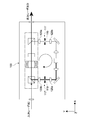
- FIG. 2 is a schematic diagram illustrating a configuration example of the optical amplifying device according to the present embodiment.
- terms such as a front stage, a rear stage, a downstream side, and an upstream side are used with reference to the traveling direction of the laser light that travels in the optical amplifying apparatus 100. That is, the side on which the laser light is incident is the front stage and the upstream side, and the side from which the laser light is emitted is the rear stage and the downstream side.
- the optical amplification apparatus 100 includes an input unit 101 to which an input laser beam I is input, an isolator unit 102, an optical amplification unit 103, and an output unit 104 that outputs the amplified laser beam to the outside.
- the laser beam output from the output unit 104 becomes the output laser beam O.
- the isolator unit 102 receives an input laser beam I input from the input unit 101.
- the isolator unit 102 includes a first PBS (polarizing beam splitter) 105, a Faraday rotator 106, a crystal rotator 107, and a second PBS 108, which are arranged substantially linearly in the x direction in the figure. These members are arranged in this order from upstream to downstream.
- the linear optical path from the first PBS 105 to the second PBS 108 is referred to as a linear optical path P1.
- the first PBS 105 transmits P-polarized light to the separation surface 105a and reflects S-polarized light. As shown in FIG. 2, the first incident surface 105b of the first PBS 105 is arranged in a direction orthogonal to the x direction, and the P-polarized light incident on the first incident surface 105b is transmitted as it is onto the linear optical path P1. Is done.
- the surface that is in a direction different from the first incident surface 105 b and that is orthogonal to the y direction in the figure is the second incident surface 105 c of the first PBS 105. S-polarized light incident on the second incident surface 105c along the y direction is reflected on the linear optical path P1.
- the first PBS 105 corresponds to the first optical element in the present embodiment.
- the P-polarized light incident on the first emission surface 105b corresponds to the first laser light L1 that is the laser light in the first polarization state incident on the first incident port.
- the S-polarized light incident on the second emission surface 105c corresponds to the second laser light L2 that is the laser light in the second polarization state incident on the second incident port.
- the input laser beam I is incident on the first incident surface 105b as the first laser beam L1. Further, laser light having the same polarization state as the P-polarized light and S-polarized light with respect to the separation surface 105a of the first PBS 105 will be described as P-polarized light and S-polarized light as they are.
- the Faraday rotator 106 is a magnetic optical crystal, and rotates the polarization direction of the laser light emitted from the first PBS 105 by 45 degrees when a magnetic field is applied.
- the crystal rotator 107 is an optical crystal having natural optical rotation such as quartz or quartz, and rotates the polarization direction of the laser light emitted from the Faraday rotator by 45 degrees in the same direction. Therefore, the polarization direction of the laser light passing through the Faraday rotator 106 and the crystal rotator 107 from the upstream side is rotated by 90 degrees. That is, P-polarized light is converted to S-polarized light, and S-polarized light is converted to P-polarized light.
- the Faraday rotator 106 and the crystal rotator 107 constitute the conversion unit 110 according to this embodiment.
- the crystal rotator 107 corresponds to a conversion element that converts the first laser light L1 whose polarization state has been converted by the Faraday rotator 106 into S-polarized light.
- the rotation of the polarization direction corresponds to the conversion of the polarization state.
- the conversion unit 110 can be realized with a simple configuration.
- the second PBS 108 reflects the first laser light L1 whose polarization state has been converted by the conversion unit 110 to become S-polarized light along a predetermined direction (y direction in the drawing). In addition, the second PBS 108 transmits the second laser light L ⁇ b> 2 whose polarization state has been converted by the conversion unit 110 into P-polarized light toward the output unit 104.
- the second PBS 108 corresponds to a second optical element in the present embodiment.
- Specific configurations of the first PBS 105, the Faraday rotator 106, the crystal rotator 107, the half-wave plate, and the second PBS 108 are not limited, and other optical elements having the same function may be used. .
- a crystalline polarization separation element such as a Glan-Thompson prism may be used instead of PBS.
- the method of emitting laser light to a member or the like in the subsequent stage is not limited, and transmission, reflection, or the like may be appropriately performed.
- the optical amplifying unit 103 amplifies the first laser light L1 reflected by the second PBS 108 and makes it incident on the second incident surface 105 c of the first PBS 105.
- the first laser beam L1 is converted to S-polarized light. Accordingly, when viewed from the first PBS 105, the first laser light L1 is incident as the second laser light L2.
- the optical amplification unit 103 includes a first filter unit 111, a first mirror 112, a first lens 113, an SOA 114 as an optical amplification element, a second lens 115, and a second lens 115. 2 mirrors 116 and a second filter unit 117.
- the first mirror 112 reflects the first laser light L 1 that has passed through the first filter unit 111 toward the first lens 113.
- the first lens 113 condenses the first laser light L1 on the incident end (incident part) 114a of the SOA 114.
- the SOA 114 amplifies the first laser beam L1 by current injection from the outside.
- the second lens 115 collimates the first laser light L1 emitted from the emission end (emission part) 114b of the SOA 114.
- the second mirror 116 reflects the collimated first laser light L1 toward the second incident surface 105 c of the first PBS 105.
- the reflected first laser light L1 enters the second incident surface 105c through the second filter unit 117 as the second laser light L2.
- the second laser light L2 (the amplified first laser light L1) incident on the second incident surface 105c is converted into P-polarized light by the conversion unit 110, and is externally output from the output unit 104 via the second PBS 108. Is output. This completes the laser light amplification method according to the present technology.
- the optical path from the exit end 114b of the SOA 114 to the entrance end 114a of the SOA 114 via the first PBS 105, the conversion unit 110, and the second PBS 108 is referred to as a circulating optical path P2.
- the input laser beam I (first laser beam L1) incident on the isolator unit 102 is amplified by the optical amplification unit 114 and then guided again to the isolator unit 102 as the second laser beam L2. . Therefore, the optical amplification device 100 according to the present technology can be realized by a single optical isolator.
- the first and second filter units 111 and 117 will be described.
- the amplified laser light is emitted from the emission end 114b (forward emission).
- ASE generated by current injection is emitted from the emission end 114b and the incidence end 114a (front-rear emission). There may occur a case in which a part of these amplified laser light and ASE is incident on the other end of the optical path P2 as unnecessary light.
- the first filter unit 111 that restricts the first unnecessary light traveling from the second PBS 118 to the incident end 114a is disposed between the second PBS 118 and the incident end 114a of the SOA 114.
- a second filter unit 117 that restricts second unnecessary light traveling from the first PBS 105 to the emission end 114b is disposed between the first PBS 105 and the emission end 114b of the SOA 114.
- the first and second filter units 111 and 117 are spatial filters capable of spatially filtering each unnecessary light.
- an optical slit 119 is used as the first and second filter portions 111 and 117.
- a pinhole or the like may be used.
- an optical slit 119 and an entrance side lens 120a and an exit side lens 120b sandwiching the optical slit 119 may be used as the first and second filter portions 111 ′ and 117 ′.
- the incident side lens 120 a and the emission side lens 120 b are lenses having substantially the same configuration, and their focal positions are matched with the position of the optical slit 119.
- the optical slit 119 can be reduced in size. Further, the length of the optical path necessary for separating unnecessary light can be shortened. As a result, downsizing of the apparatus can be realized.
- emitted from the output side lens 120b may be adjusted by designing the output side lens 120b suitably.
- various configurations may be employed to realize the first and second filter units 111 and 117.
- the first and second filter units 111 and 117 may have different configurations.
- FIG. 4 is a schematic diagram illustrating a configuration example of the optical amplifying device according to the present embodiment.
- the arrangement of the first PBS 205 is different from that of the optical amplifying device 100 shown in FIG.
- the extending direction of the straight optical path P1 is the x direction
- the traveling direction of the second laser light L2 (amplified first laser light L1) traveling toward the second incident surface 205c of the first PBS 205 is the y direction.
- the first PBS 205 is arranged with an angle ⁇ rotated in the xy plane. That is, if the direction orthogonal to both the x direction and the y direction is the z direction, the angle ⁇ is rotated counterclockwise as viewed from the z direction with the z direction as the rotation axis direction. Accordingly, the first and second incident surfaces 205b and 205c and the separation surface 205a of the first PBS 205 are also rotated by an angle ⁇ within the xy plane.
- the input laser beam I (first laser beam L1) input to the input unit 201 is not affected by the rotation of the first PBS 205 and is emitted onto the linear optical path P1. Then, the light enters the circular optical path P2, is amplified, and enters the first PBS 205 along the y direction as the second laser light L2. Since the separation surface 205a of the first PBS 205 is rotated by the angle ⁇ , the second laser light L2 is reflected toward the conversion unit 210 so as to travel obliquely by the angle 2 ⁇ from the linear optical path P1 by the separation surface 205a.
- the rotation angle ⁇ of the first PBS 205 is set so that the angle 2 ⁇ with respect to the straight optical path P1 is a predetermined angle.
- the amplified laser light emitted from the SOA 214 travels from the second PBS 208 toward the incident portion 214a of the SOA 214 as the first unnecessary light L3. Since the amplified laser light travels at an angle of 2 ⁇ from the straight optical path P1, the unnecessary light L3 reflected by the second PBS 208 travels at an angle of 2 ⁇ with respect to the circulating optical path P2. As a result, the first unnecessary light L3 can be easily separated by the first filter unit 211, and the incidence on the SOA 214 can be regulated with high accuracy.
- the second unnecessary light L4 travels on the straight optical path P1 and enters the first PBS 205. Since the separation surface 205a of the first PBS 205 is rotated by an angle ⁇ , the second unnecessary light L4 reflected by the separation surface 205a travels obliquely by an angle 2 ⁇ with respect to the circulating optical path P2. As a result, the second unnecessary light L4 can be easily separated by the second filter unit 217, and the incidence on the SOA 214 can be regulated with high accuracy.
- the amplified second laser light L2 travels obliquely by an angle 2 ⁇ from the linear optical path P1, so that, for example, the conversion characteristics of the conversion unit 210, the output from the output unit 204, and the like are not affected, so that the linear optical path
- the angle 2 ⁇ from P1 may be adjusted as appropriate. For example, by setting the angle 2 ⁇ within a range of ⁇ 2 degrees or more and +2 degrees or less, it is possible to output the amplified laser beam from the output unit 204 without any problem.
- the rotation angle ⁇ of the first PBS 205 is in the range of ⁇ 1 degree or more and +1 degree or less.
- how to set the positive / negative of the rotation direction is not limited. In any case, the first PBS 205 may be rotated in either the left or right direction when viewed from the z direction.
- the angle 2 ⁇ from the straight optical path P1 (the rotation angle ⁇ of the first PBS 205) is not limited to the above range.
- the angle 2 ⁇ (angle ⁇ ) can be adjusted by appropriately setting the configuration and arrangement position of each of the Faraday rotator, crystal rotator, and other members.
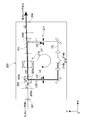
- FIG. 5 is a schematic diagram illustrating a configuration example of an optical amplifying device according to the third embodiment.
- This optical amplifying apparatus 300 can amplify broadband laser light including laser light having a plurality of wavelengths.
- each of the laser beams having the wavelengths ⁇ 1 and ⁇ 2 is referred to as a laser beam ⁇ 1 and a laser beam ⁇ 2.
- the input laser beam I including the laser beams ⁇ 1 and ⁇ 2 is input from the input unit 301 and enters the isolator unit 302 as the first laser beam L1.
- a crystal rotator 307 having natural optical rotation is used as the conversion element disposed at the subsequent stage of the Faraday rotator 306.
- the rotation angle by the Faraday rotator 306 depends on the wavelength of the incident laser light.
- the wavelength dependence of the rotation angle of the Faraday rotator 306 can be compensated by the wavelength dependence of the rotation angle by the crystal rotator 307.
- both the laser beams ⁇ 1 and ⁇ 2 are converted from P-polarized light to S-polarized light by the Faraday rotator 306 and the crystal rotator 307.
- the optical amplifying unit 303 includes a wavelength separation mirror 320, a reflection mirror 321, a plurality of SOAs 314a and 314b, a reflection mirror 322, and a multiplexing mirror 323.
- the wavelength separation mirror 320 reflects the laser beam ⁇ 1 of the first laser beam L1 emitted from the second PBS 308 to the circular optical path P2 toward the SOA 314a and transmits the laser beam ⁇ 2.
- the reflection mirror 321 reflects the laser beam ⁇ 2 transmitted through the wavelength separation mirror 320 toward the SOA 314b.
- the wavelength separation mirror 320 and the reflection mirror 321 constitute a separation unit that separates the first laser light L1 into a plurality of separation laser lights for each wavelength according to the present embodiment.
- the laser beams ⁇ 1 and ⁇ 2 correspond to a plurality of separated laser beams.
- the first filter unit 311 is disposed between the second PBS 308 and the separation unit.
- the SOAs 314a and 314b amplify the laser beams ⁇ 1 and ⁇ 2.
- a plurality of SOAs 314 and a and 314b having different optical amplification characteristics according to the wavelengths ⁇ 1 and ⁇ 2 of the laser light high-accuracy optical amplification is possible.
- the reflection mirror 322 reflects the laser beam ⁇ 2 amplified by the SOA 314b toward the multiplexing mirror 323 along the y direction.
- the combining mirror 323 combines the laser light ⁇ 1 amplified by the SOA 314a and the laser light ⁇ 2 reflected by the reflecting mirror 322, and emits the resultant light along the y direction.
- the amplified laser beams ⁇ 1 and ⁇ 2 are incident on the first PBS 305 as the second laser beam L2.
- the second laser beam L2 is emitted to the output unit 304 via the isolator unit 302.
- the reflection mirror 322 and the combining mirror 323 constitute a combining unit that can combine the laser beams ⁇ 1 and ⁇ 2 amplified by the plurality of SOAs 314a and 314b according to the present embodiment.
- the second filter unit 317 is disposed between the first PBS 305 and the synthesis unit.
- the wavelengths of the laser beams ⁇ 1 and ⁇ 2 having a plurality of wavelengths, the number of the plurality of laser beams included in the input laser beam I, and the like are not limited.
- the same number of SOAs may be arranged for each of laser beams having different wavelengths.
- each of the laser beams having a plurality of wavelengths may be individually input to the optical amplifying apparatus 300 at a predetermined timing and amplified.
- a plurality of excitation lights can be amplified.
- the embodiment is not limited to this.
- FIG. 6 is a schematic diagram illustrating a configuration example of an optical amplifying device according to the fourth embodiment.
- FIG. 6A is a schematic diagram illustrating the entire optical amplification layer device 400.
- FIG. 6B is a schematic view of the mirror unit 430 configured in the optical amplification unit 403 as seen from the x direction.
- the second PBS 408 is arranged with its optical axis rotated by 45 degrees. That is, the second PBS 108 shown in FIG. 2 is configured to be inclined 45 degrees toward the back side of the drawing with the optical axis direction (x direction) of the first laser light L1 as the rotation axis.
- the first laser light L1 reflected by the second PBS 408 is emitted at an angle of 45 degrees upward (z direction) from the xy plane direction.
- the mirror unit 430 is configured to return the first laser beam L1 to the xy plane in which the circulating optical path P2 is configured.
- the first laser light L1 emitted from the second PBS 408 is reflected by the first mirror 431 toward the second mirror 432.
- the second mirror 423 is disposed in the xy plane, and reflects the first laser light L1 reflected by the first mirror 431 toward the first filter unit 411 along the y direction. It can be said that the optical path in the mirror unit 430 is also a part of the circulating optical path P2.
- the optical amplification method according to the present technology can be realized even when the conversion unit 410 includes only the Faraday rotator 406.
- the configuration of the conversion unit 410 can be simplified, and the size of the apparatus can be reduced.
- the P-polarized first laser light L1 is not converted to S-polarized light.
- the first laser beam L1 is converted into S-polarized light by being reflected by the second PBS 408.
- the second PBS 408 converts the first laser light L1 whose polarization state has been converted by the Faraday rotator 406 into S-polarized light and emits it.
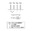
- FIG. 7 is a schematic diagram for explaining this, and is a diagram showing a waveform of a pulse laser beam.
- the amplification operation Amp by the SOA is executed at the same cycle as the pulse cycle Tp of the pulse laser beam. That is, the amplification operation Amp is executed in accordance with the timing at which the pulse enters the SOA. Then, at substantially the same timing, amplified laser light is emitted from the emission end of the SOA.
- T1 L / C L: Optical path length of the circulating optical path (m) C ... speed of light (in air: 3 ⁇ 10 8 m / s)
- the optical path length L of the circuit is set so that the value T1 is different from an integer multiple of the pulse period Tp, that is, the following equation is satisfied.
- optical amplification device and the light source device according to the present technology are applied to a microscope system.
- the optical amplification device and the light source device according to the present technology can be applied to various systems in the medical / biological field such as an endoscope system.
- the present technology can be applied to systems and devices in various fields such as an optical recording system and a semiconductor exposure apparatus.
- a configuration for amplifying each of ⁇ 2 and the like may be arbitrarily applied to the optical amplifying device according to another embodiment.
- various techniques and configurations described in the first to fourth embodiments may be employed.
- this technique can also take the following structures.
- a conversion unit including a Faraday rotator capable of converting the polarization state of laser light; A first laser beam that has a first incident port and a second incident port that is different from the first incident port and is a laser beam in a first polarization state that is incident on the first incident port.
- a second optical beam that emits a second laser beam, which is a laser beam having a second polarization state different from the first polarization state incident on the second entrance, toward the conversion unit.
- the first laser beam whose polarization state is converted by the conversion unit can be emitted as the laser beam of the second polarization state, and the second laser beam whose polarization state is converted by the conversion unit is externally used.
- a second optical element capable of emitting light toward the output to An optical amplifying element that amplifies the first laser light emitted as the laser light in the second polarization state by the second optical element, and the amplified first laser light is converted into the first laser light;
- An optical amplifying apparatus comprising: an optical amplifying unit that causes the optical element to enter the second incident port as the second laser beam.
- the optical amplification device includes a conversion element that converts the first laser light whose polarization state is converted by the Faraday rotator into laser light of the second polarization state
- the second optical element is an optical amplification device that emits the first laser light converted into the laser light in the second polarization state by the conversion element.
- the optical amplification device is an optical amplifying device that converts the first laser light whose polarization state is converted by the Faraday rotator into a laser beam having the second polarization state and emits the laser light.
- the optical amplification device is a crystal rotator which is an optical crystal having optical rotation, or a half-wave plate.
- the optical amplification device has an incident part on which the first laser light emitted from the second optical element is incident, and an emission part from which the amplified first laser light is emitted
- the optical amplification unit is disposed between the second optical element and the incident unit, and includes a first filter unit that regulates first unnecessary light that travels from the second optical element to the incident unit, and the first optical unit. And a second filter unit that is disposed between the first optical element and the emission unit and restricts second unnecessary light that travels from the first optical element to the emission unit.
- the optical amplification device includes: a separation unit capable of separating the first laser beam emitted from the second optical element into a plurality of separated laser beams for each wavelength; and each of the separated plurality of separated laser beams.
- An optical amplifying device comprising: a plurality of optical amplifying elements that amplify the light; and a combining unit capable of combining the plurality of separated lights amplified by the plurality of optical amplifying elements.
- the optical amplifying device is disposed between the second optical element and the separation unit, and includes a first filter unit that regulates first unnecessary light that travels from the second optical element to the separation unit, and the first filter unit. And a second filter unit that is disposed between the first optical element and the combining unit and restricts second unnecessary light traveling from the first optical element to the combining unit.
- the optical amplification device according to (5) or (7), The first filter unit spatially filters the first unnecessary light
- the second filter unit is an optical amplification device that spatially filters the second unnecessary light.
- the optical amplification device (9) The optical amplification device according to (8), The first optical element transmits the first laser light incident on the first incident port onto a predetermined optical path toward the conversion unit, and enters the second incident port. An optical amplifying apparatus that reflects laser light toward the conversion unit so as to travel obliquely at a predetermined angle from the predetermined optical path. (10) The optical amplification device according to (9), The optical amplification device, wherein the predetermined angle is included in a range of not less than ⁇ 2 degrees and not more than +2 degrees.
- the optical amplifying device according to any one of (1) to (10),
- the first optical element emits a pulsed laser beam incident on the first incident port toward the conversion unit as the first laser beam
- the optical amplification element has an incident part on which the first laser light emitted from the second optical element is incident, and an emission part from which the amplified first laser light is emitted
- the optical amplifying unit is configured such that an optical path length of a circular optical path from the emitting unit to the incident unit via the first optical element, the converting unit, and the second optical element
- An optical amplifying apparatus that is set so that a value divided by a speed is different from an integer multiple of a pulse period of the pulse laser beam.
- L1 First laser light
- L2 Second laser light
- L3 First unnecessary light
- P1 Linear optical path
- P2 Circulating optical path
- Light source device 30 DESCRIPTION OF SYMBOLS 40 ...
- Laser light source part 100, 200, 300, 400 ...
- Optical amplification apparatus 103, 303, 403 ...
- PBS polarization beam splitter
- second PBS 110, 210, 410 conversion unit 111, 211, 311, 411 ... first filter unit 114, 214, 314a, 314b ... SOA 114a, 214a ... incidence end 114b, 214b ... emission end 117, 217, 317 ... second filter section 1000 ... microscope system
Landscapes
- Physics & Mathematics (AREA)
- Condensed Matter Physics & Semiconductors (AREA)
- General Physics & Mathematics (AREA)
- Electromagnetism (AREA)
- Optics & Photonics (AREA)
- Optical Modulation, Optical Deflection, Nonlinear Optics, Optical Demodulation, Optical Logic Elements (AREA)
- Semiconductor Lasers (AREA)
- Lasers (AREA)
Abstract
L'invention concerne un dispositif d'amplification optique qui est pourvu : d'une unité de conversion permettant de convertir l'état de polarisation ; d'un premier élément optique, qui possède des premier et second ports d'incidence et qui émet, vers l'unité de conversion, un premier faisceau laser entré par le premier port d'incidence, ledit premier faisceau laser étant dans un premier état de polarisation, et un second faisceau laser entré par le second port d'incidence, ledit second faisceau laser étant dans un second état de polarisation ; d'un second élément optique, qui peut émettre, sous la forme d'un faisceau laser dans le second état de polarisation, le premier faisceau laser dont l'état de polarisation a été converti, et qui peut émettre, vers une unité de sortie à l'extérieur, le second faisceau laser dont l'état de polarisation a été converti ; d'une unité d'amplification optique, qui amplifie le premier faisceau laser émis sous la forme du faisceau laser dans le second état de polarisation au moyen du second élément optique, et qui applique, à titre de second faisceau laser, le premier faisceau laser amplifié au second port d'incidence du premier élément optique.
Applications Claiming Priority (2)
| Application Number | Priority Date | Filing Date | Title |
|---|---|---|---|
| JP2015048985A JP2016171156A (ja) | 2015-03-12 | 2015-03-12 | 光増幅装置、及び光源装置 |
| JP2015-048985 | 2015-03-12 |
Publications (1)
| Publication Number | Publication Date |
|---|---|
| WO2016142980A1 true WO2016142980A1 (fr) | 2016-09-15 |
Family
ID=56880020
Family Applications (1)
| Application Number | Title | Priority Date | Filing Date |
|---|---|---|---|
| PCT/JP2015/006443 Ceased WO2016142980A1 (fr) | 2015-03-12 | 2015-12-24 | Dispositif d'amplification optique et dispositif source de lumière |
Country Status (2)
| Country | Link |
|---|---|
| JP (1) | JP2016171156A (fr) |
| WO (1) | WO2016142980A1 (fr) |
Cited By (3)
| Publication number | Priority date | Publication date | Assignee | Title |
|---|---|---|---|---|
| CN106384932A (zh) * | 2016-11-29 | 2017-02-08 | 中国工程物理研究院激光聚变研究中心 | 一种基于波前畸变校正的多程激光放大器及其使用方法 |
| CN107196182A (zh) * | 2017-07-19 | 2017-09-22 | 中国工程物理研究院激光聚变研究中心 | 一种离轴八程激光放大装置 |
| CN115207755A (zh) * | 2022-08-06 | 2022-10-18 | 苏州国顺激光技术有限公司 | 可调增益放大器及其增益调节方法 |
Families Citing this family (1)
| Publication number | Priority date | Publication date | Assignee | Title |
|---|---|---|---|---|
| WO2023157268A1 (fr) * | 2022-02-21 | 2023-08-24 | ギガフォトン株式会社 | Système laser et procédé de production de dispositif électronique |
Citations (8)
| Publication number | Priority date | Publication date | Assignee | Title |
|---|---|---|---|---|
| JPH01232543A (ja) * | 1988-03-11 | 1989-09-18 | Hitachi Ltd | 光学式情報記録再生装置 |
| JPH03111807A (ja) * | 1989-09-26 | 1991-05-13 | Shin Etsu Chem Co Ltd | 光アイソレータ |
| JPH03135514A (ja) * | 1989-10-20 | 1991-06-10 | Matsushita Electric Ind Co Ltd | 光アイソレータ |
| JPH10270781A (ja) * | 1997-03-27 | 1998-10-09 | Sony Corp | レーザ光発生方法及びその装置 |
| JP2003524889A (ja) * | 1999-10-15 | 2003-08-19 | ジェイ エム エー アール リサーチ、インク | 光線補正レーザ増幅器 |
| JP3850866B2 (ja) * | 2003-06-19 | 2006-11-29 | 日本電信電話株式会社 | 光変調装置 |
| JP2011517066A (ja) * | 2008-03-31 | 2011-05-26 | エレクトロ サイエンティフィック インダストリーズ インコーポレーテッド | マルチパス光パワー増幅器 |
| JP2013504216A (ja) * | 2009-09-03 | 2013-02-04 | アクサン・テクノロジーズ・インコーポレーテッド | Oct医療用画像化のためのフィルタase掃引源 |
-
2015
- 2015-03-12 JP JP2015048985A patent/JP2016171156A/ja active Pending
- 2015-12-24 WO PCT/JP2015/006443 patent/WO2016142980A1/fr not_active Ceased
Patent Citations (8)
| Publication number | Priority date | Publication date | Assignee | Title |
|---|---|---|---|---|
| JPH01232543A (ja) * | 1988-03-11 | 1989-09-18 | Hitachi Ltd | 光学式情報記録再生装置 |
| JPH03111807A (ja) * | 1989-09-26 | 1991-05-13 | Shin Etsu Chem Co Ltd | 光アイソレータ |
| JPH03135514A (ja) * | 1989-10-20 | 1991-06-10 | Matsushita Electric Ind Co Ltd | 光アイソレータ |
| JPH10270781A (ja) * | 1997-03-27 | 1998-10-09 | Sony Corp | レーザ光発生方法及びその装置 |
| JP2003524889A (ja) * | 1999-10-15 | 2003-08-19 | ジェイ エム エー アール リサーチ、インク | 光線補正レーザ増幅器 |
| JP3850866B2 (ja) * | 2003-06-19 | 2006-11-29 | 日本電信電話株式会社 | 光変調装置 |
| JP2011517066A (ja) * | 2008-03-31 | 2011-05-26 | エレクトロ サイエンティフィック インダストリーズ インコーポレーテッド | マルチパス光パワー増幅器 |
| JP2013504216A (ja) * | 2009-09-03 | 2013-02-04 | アクサン・テクノロジーズ・インコーポレーテッド | Oct医療用画像化のためのフィルタase掃引源 |
Cited By (5)
| Publication number | Priority date | Publication date | Assignee | Title |
|---|---|---|---|---|
| CN106384932A (zh) * | 2016-11-29 | 2017-02-08 | 中国工程物理研究院激光聚变研究中心 | 一种基于波前畸变校正的多程激光放大器及其使用方法 |
| CN106384932B (zh) * | 2016-11-29 | 2023-08-11 | 中国工程物理研究院激光聚变研究中心 | 一种基于波前畸变校正的多程激光放大器及其使用方法 |
| CN107196182A (zh) * | 2017-07-19 | 2017-09-22 | 中国工程物理研究院激光聚变研究中心 | 一种离轴八程激光放大装置 |
| CN107196182B (zh) * | 2017-07-19 | 2023-08-15 | 中国工程物理研究院激光聚变研究中心 | 一种离轴八程激光放大装置 |
| CN115207755A (zh) * | 2022-08-06 | 2022-10-18 | 苏州国顺激光技术有限公司 | 可调增益放大器及其增益调节方法 |
Also Published As
| Publication number | Publication date |
|---|---|
| JP2016171156A (ja) | 2016-09-23 |
Similar Documents
| Publication | Publication Date | Title |
|---|---|---|
| CN103026282B (zh) | 可调多激光脉冲扫描显微镜和操作该显微镜的方法 | |
| US20010028031A1 (en) | Apparatus for combining light and confocal scanning microscope | |
| US11304286B2 (en) | Polarizer | |
| WO2016142980A1 (fr) | Dispositif d'amplification optique et dispositif source de lumière | |
| JP6530405B2 (ja) | ビームコンバイナ、音響光学ビームコンバイナ、光源、顕微鏡及び使用 | |
| WO2011108761A1 (fr) | Dispositif laser, système laser, et appareil générant un rayonnement ultraviolet extrême | |
| JP5463913B2 (ja) | 広帯域光増幅器、光パルス発生装置及び光学機器 | |
| US20020093632A1 (en) | Three-dimensional fabrication using entangled-photon lithography | |
| JP2016516219A (ja) | ランダムアクセス誘導放出抑制(sted)顕微鏡 | |
| JP2016529563A (ja) | 音響光学装置を備えている顕微鏡 | |
| CN119667965B (zh) | 偏振与光谱组合的激光合成系统及其方法 | |
| US9036251B2 (en) | Slab amplification device, laser apparatus, and extreme ultraviolet light generation system | |
| TWI583262B (zh) | 驅動器雷射配置、euv輻射產生設備及用於放大脈衝雷射輻射的方法 | |
| WO2014119198A1 (fr) | Dispositif laser et dispositif de génération de lumière ultraviolette extrême | |
| US9954339B2 (en) | Laser unit and extreme ultraviolet light generating system | |
| US12585136B2 (en) | Combination device and optical system | |
| CN100397139C (zh) | 利用受激布里渊散射相位共轭镜进行自相位控制的装置和方法 | |
| US9158101B2 (en) | Device and method for distributing illumination light and detected light in a microscope | |
| US10777963B2 (en) | Laser device | |
| JP7679605B2 (ja) | パルス分光装置及びマルチファイバ用照射ユニット | |
| JP5573063B2 (ja) | 光源装置 | |
| US20230130928A1 (en) | Amplified laser light with multiple optical amplifiers | |
| JP2020148911A (ja) | 量子もつれ光子対増幅装置及び量子もつれ光子対増幅方法 | |
| US20080193081A1 (en) | Microscope | |
| JP2009177037A (ja) | 光分岐装置およびその方法 |
Legal Events
| Date | Code | Title | Description |
|---|---|---|---|
| 121 | Ep: the epo has been informed by wipo that ep was designated in this application |
Ref document number: 15884478 Country of ref document: EP Kind code of ref document: A1 |
|
| NENP | Non-entry into the national phase |
Ref country code: DE |
|
| 122 | Ep: pct application non-entry in european phase |
Ref document number: 15884478 Country of ref document: EP Kind code of ref document: A1 |