WO2016143143A1 - 処置具挿入補助具 - Google Patents
処置具挿入補助具 Download PDFInfo
- Publication number
- WO2016143143A1 WO2016143143A1 PCT/JP2015/057389 JP2015057389W WO2016143143A1 WO 2016143143 A1 WO2016143143 A1 WO 2016143143A1 JP 2015057389 W JP2015057389 W JP 2015057389W WO 2016143143 A1 WO2016143143 A1 WO 2016143143A1
- Authority
- WO
- WIPO (PCT)
- Prior art keywords
- outer tube
- end side
- tube
- inner tube
- engaged
- Prior art date
- Legal status (The legal status is an assumption and is not a legal conclusion. Google has not performed a legal analysis and makes no representation as to the accuracy of the status listed.)
- Ceased
Links
Images




Classifications
-
- A—HUMAN NECESSITIES
- A61—MEDICAL OR VETERINARY SCIENCE; HYGIENE
- A61B—DIAGNOSIS; SURGERY; IDENTIFICATION
- A61B1/00—Instruments for performing medical examinations of the interior of cavities or tubes of the body by visual or photographical inspection, e.g. endoscopes; Illuminating arrangements therefor
- A61B1/00064—Constructional details of the endoscope body
- A61B1/00105—Constructional details of the endoscope body characterised by modular construction
-
- A—HUMAN NECESSITIES
- A61—MEDICAL OR VETERINARY SCIENCE; HYGIENE
- A61B—DIAGNOSIS; SURGERY; IDENTIFICATION
- A61B1/00—Instruments for performing medical examinations of the interior of cavities or tubes of the body by visual or photographical inspection, e.g. endoscopes; Illuminating arrangements therefor
- A61B1/00131—Accessories for endoscopes
- A61B1/0014—Fastening element for attaching accessories to the outside of an endoscope, e.g. clips, clamps or bands
-
- A—HUMAN NECESSITIES
- A61—MEDICAL OR VETERINARY SCIENCE; HYGIENE
- A61B—DIAGNOSIS; SURGERY; IDENTIFICATION
- A61B1/00—Instruments for performing medical examinations of the interior of cavities or tubes of the body by visual or photographical inspection, e.g. endoscopes; Illuminating arrangements therefor
- A61B1/00147—Holding or positioning arrangements
- A61B1/00154—Holding or positioning arrangements using guiding arrangements for insertion
-
- A—HUMAN NECESSITIES
- A61—MEDICAL OR VETERINARY SCIENCE; HYGIENE
- A61B—DIAGNOSIS; SURGERY; IDENTIFICATION
- A61B1/00—Instruments for performing medical examinations of the interior of cavities or tubes of the body by visual or photographical inspection, e.g. endoscopes; Illuminating arrangements therefor
- A61B1/005—Flexible endoscopes
- A61B1/0051—Flexible endoscopes with controlled bending of insertion part
- A61B1/0055—Constructional details of insertion parts, e.g. vertebral elements
-
- A—HUMAN NECESSITIES
- A61—MEDICAL OR VETERINARY SCIENCE; HYGIENE
- A61B—DIAGNOSIS; SURGERY; IDENTIFICATION
- A61B1/00—Instruments for performing medical examinations of the interior of cavities or tubes of the body by visual or photographical inspection, e.g. endoscopes; Illuminating arrangements therefor
- A61B1/012—Instruments for performing medical examinations of the interior of cavities or tubes of the body by visual or photographical inspection, e.g. endoscopes; Illuminating arrangements therefor characterised by internal passages or accessories therefor
- A61B1/018—Instruments for performing medical examinations of the interior of cavities or tubes of the body by visual or photographical inspection, e.g. endoscopes; Illuminating arrangements therefor characterised by internal passages or accessories therefor for receiving instruments
-
- A—HUMAN NECESSITIES
- A61—MEDICAL OR VETERINARY SCIENCE; HYGIENE
- A61B—DIAGNOSIS; SURGERY; IDENTIFICATION
- A61B17/00—Surgical instruments, devices or methods
- A61B17/34—Trocars; Puncturing needles
- A61B17/3417—Details of tips or shafts, e.g. grooves, expandable, bendable; Multiple coaxial sliding cannulas, e.g. for dilating
- A61B17/3421—Cannulas
-
- A—HUMAN NECESSITIES
- A61—MEDICAL OR VETERINARY SCIENCE; HYGIENE
- A61B—DIAGNOSIS; SURGERY; IDENTIFICATION
- A61B1/00—Instruments for performing medical examinations of the interior of cavities or tubes of the body by visual or photographical inspection, e.g. endoscopes; Illuminating arrangements therefor
- A61B1/00064—Constructional details of the endoscope body
- A61B1/00071—Insertion part of the endoscope body
-
- A—HUMAN NECESSITIES
- A61—MEDICAL OR VETERINARY SCIENCE; HYGIENE
- A61B—DIAGNOSIS; SURGERY; IDENTIFICATION
- A61B1/00—Instruments for performing medical examinations of the interior of cavities or tubes of the body by visual or photographical inspection, e.g. endoscopes; Illuminating arrangements therefor
- A61B1/00131—Accessories for endoscopes
- A61B1/00133—Drive units for endoscopic tools inserted through or with the endoscope
-
- A—HUMAN NECESSITIES
- A61—MEDICAL OR VETERINARY SCIENCE; HYGIENE
- A61B—DIAGNOSIS; SURGERY; IDENTIFICATION
- A61B1/00—Instruments for performing medical examinations of the interior of cavities or tubes of the body by visual or photographical inspection, e.g. endoscopes; Illuminating arrangements therefor
- A61B1/005—Flexible endoscopes
- A61B1/01—Guiding arrangements therefore
-
- A—HUMAN NECESSITIES
- A61—MEDICAL OR VETERINARY SCIENCE; HYGIENE
- A61B—DIAGNOSIS; SURGERY; IDENTIFICATION
- A61B17/00—Surgical instruments, devices or methods
- A61B17/00234—Surgical instruments, devices or methods for minimally invasive surgery
-
- A—HUMAN NECESSITIES
- A61—MEDICAL OR VETERINARY SCIENCE; HYGIENE
- A61B—DIAGNOSIS; SURGERY; IDENTIFICATION
- A61B17/00—Surgical instruments, devices or methods
- A61B17/34—Trocars; Puncturing needles
- A61B17/3417—Details of tips or shafts, e.g. grooves, expandable, bendable; Multiple coaxial sliding cannulas, e.g. for dilating
- A61B17/3421—Cannulas
- A61B2017/3445—Cannulas used as instrument channel for multiple instruments
Definitions
- the present invention relates to a treatment instrument insertion aid for assisting insertion of a treatment instrument such as an endoscope or forceps into a body.
- a treatment tool insertion aid that assists the insertion of a treatment tool into the body is used.
- a multi-lumen tube endoscope that is integrally fixed with a resin body is known.
- the insertability of the treatment instrument during use can be improved (for example, a patent) Reference 1).
- the treatment instrument insertion aid has the disadvantage that the number of inner tubes, diameter, etc. cannot be changed.
- the inner tube is surrounded by a flexible outer tube, and the engaged portion provided on the outer peripheral surface of the inner tube is engaged with the engaging portion provided on the inner peripheral surface of the outer tube. Is done. Thereby, an inner tube can be latched to the predetermined location in an outer tube.
- An object of the present invention is to provide a treatment instrument insertion aid that can eliminate such inconvenience and can bend the outer tube satisfactorily.
- the present invention is a treatment instrument insertion aid for assisting insertion of a treatment instrument into the body, which has flexibility and is spaced apart in the circumferential direction on the inner peripheral surface.
- An outer tube having a plurality of guide portions extending in the axial direction from the side to the base end side, and a guided portion having flexibility, extending in the axial direction from the tip end side to the base end side, and being engaged with the guide portion
- a plurality of rail members each having a plurality of rail members, and a flexible inner member having an engaged portion that engages with an engaging portion formed between the inner peripheral surface of the outer tube and the adjacent rail.
- Each of the plurality of rail members is fixed to the outer tube at a single location.
- each of the plurality of rail members is fixed to the outer tube at only one position. Therefore, when the outer tube is bent, each rail member follows the bending of the outer tube. Bend. Therefore, the outer tube can be bent well.
- the plurality of rail members are made of a material harder than the material of the outer tube.
- the outer tube can be easily bent, and the shape of the second engaging portion formed between the inner peripheral surface of the outer tube and the adjacent rail member can be ensured satisfactorily. Become.
- the portion of the outer tube to which the plurality of rail members are fixed is made of a material that is harder than the material of the other portion of the outer tube.
- the rail member can be fixed to the portion of the outer tube that is difficult to deform, the shape of the second engagement portion formed between the inner peripheral surface of the outer tube and the adjacent rail member is ensured satisfactorily. It becomes possible.
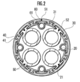
- FIG. 2 is a cross-sectional view taken along line AA in FIG.
- FIG. 4B is a perspective view of the bent inner tube of FIG. 4A.
- FIG. 5B is a sectional view taken along line BB in FIG. 5A.
- FIG. 5B is a cross-sectional view taken along line CC of FIG. 5A.
- the treatment instrument insertion aid 10 according to the embodiment of the present invention will be described.
- the treatment instrument insertion assisting tool 10 is used to assist insertion of a treatment instrument (not shown) such as an endoscope, forceps, and scalpel into the body.
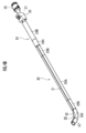
- the treatment instrument insertion assisting tool 10 is mainly composed of an inner tube 20, an outer tube 30, and a rail member 40 as shown in FIGS.
- a plurality of rail members 40 are attached to the outer tube 30, and one or a plurality of inner tubes 20 are inserted therein.
- the outer tube 30 is a cylindrical body having flexibility, and includes a plurality of guide portions 31 extending in the axial direction from the distal end side to the proximal end side on the inner wall surface.
- the guide portions 31 are dovetail grooves formed on the inner wall surface of the outer tube 30 and are formed on the inner wall surface at equal intervals in the circumferential direction.
- the dovetail groove is formed in a protruding portion that protrudes toward the central axis, and has a rectangular cross-sectional shape on both the opening and the back side.
- the shape of the dovetail is not limited to this, and it may be a substantially trapezoidal shape extending to the back side of the opening, or the opening may be rectangular and the back side may be substantially circular.
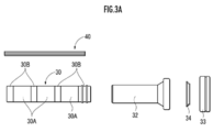
- the outer tube 30 includes a soft portion 30A made of a soft material such as polypropylene and vinyl chloride, and a soft material such as rubber, and is harder than the soft portion 30A and includes ABS, polycarbonate, and the like.
- the hard portions 30B made of a hard material such as hard plastic or hard rubber are alternately coupled in the axial direction. However, both end portions in the axial direction of the outer tube 30 are composed of hard portions 30B.
- the outer tube 30 may be partially or entirely transparent or translucent.
- a first wire member 51 is embedded in the peripheral wall portion of the outer tube 30 in the axial direction from the distal end side to the proximal end side.
- the first wire member 51 extends rearward from the base end portion of the outer tube 30, and the outer wire 30 is moved around the outer tube 30 by operating the first wire member operation portion (not shown). It can be bent in the direction and its tip can be directed in a desired direction.
- the first wire member operation unit temporarily fixes the operation of the first wire member 51 by, for example, a ratchet mechanism, thereby temporarily fixing the shape of the first wire member 51 and moving the distal end portion of the outer tube 30 in a predetermined direction. It can maintain the state toward.
- the rail member 40 is made of a hard material that is the same as or equivalent to the hard portion 30B, for example, a hard material such as ABS, polycarbonate, or hard rubber, and is a long body having flexibility.
- the rail member 40 includes a guided portion 41 that extends in the axial direction from the distal end side to the proximal end side on the outer surface.
- the guided portion 41 is a protrusion formed on the outer surface of the rail member 40.
- the guided portion 41 may be formed intermittently.
- the protrusion is formed in a shape that engages with the guide portion 31 of the outer tube 30, and has a rectangular cross-sectional shape along with the outer side and the neck portion.
- the cross-sectional shape of the protrusion is not limited to this, and may be, for example, a substantially trapezoidal shape spreading to the back side, a substantially circular outer side, and a rectangular neck part.
- a dovetail groove is formed by the inner peripheral surface of the outer tube 30 and the left and right side surfaces of the rail member 40 adjacent to each other, and this dovetail constitutes the engaging portion 50.
- the dovetail has a rectangular cross-sectional shape on both the opening and the back side, as shown in FIG.
- the cross-sectional shape of the dovetail may be, for example, a substantially trapezoidal shape that spreads further to the back than the opening, a rectangular opening and a substantially circular back.
- the rail member 40 has a guided portion 41 engaged with the guiding portion 31, and the distal end portion of the rail member 40 is bonded to the hard portion 30 ⁇ / b> B on the most distal end side of the outer tube 30.
- the other part of the rail member 40 is not fixed to the outer tube 30.
- a guide pipe 32, an air leakage prevention ring 33 and a valve seat 34 are attached to the proximal end side of the outer tube 30.
- the guide pipe 32 is a member that connects the outer tube 30 and the air leakage prevention ring 33, and is formed of a metal such as stainless steel or a hard material such as resin.
- the air leakage prevention ring 33 is bonded to the valve seat 34.
- the air leakage prevention ring 33 is detachably attached to the guide pipe 32.
- the valve seat 34 has a plurality of holes through which the inner tube 20 is inserted.
- the guide pipe 32 is a member that connects the outer tube 30 and the air leakage prevention ring 33, and is formed of a metal such as stainless steel.
- the air leakage prevention ring 33 is bonded to the valve seat 34.
- the air leakage prevention ring 33 is detachably attached to the guide pipe 32.
- the valve seat 34 has a plurality of holes through which the inner tube 20 is inserted.
- the inner tube 20 is a flexible cylindrical body through which a treatment instrument such as an endoscope, forceps, and scalpel can be inserted.
- the inner tube 20 may have one channel for inserting the treatment tool, or two or more channels.
- the inner tube 20 has a hydrophilic process on the outer peripheral surface. Each inner tube 20 can be inserted into and removed from the outer tube 30 with the rail member 40 engaged with the inner peripheral surface according to the procedure.
- the inner tube 20 has the same outer diameter, but may have different outer diameters.
- the inner tube 20 is made of a soft material such as polypropylene and vinyl chloride, a soft material such as rubber, and a soft portion 20A.
- the inner tube 20 is harder than the soft portion 20A and is made of ABS, polycarbonate,
- a hard portion 20A made of a hard material such as hard plastic or hard rubber is connected in the axial direction. Both end portions in the axial direction of the inner tube 20 are composed of hard portions 20B, and an intermediate portion between the hard portions 20B is a soft portion 20A.
- the inner tube 20 has an engaged portion 21 that can be slid by engaging with the engaging portion 50 from the distal end to the proximal end of the outer peripheral surface, and an insertion depth.
- a scale (not shown) for grasping is provided.
- the engaged portion 21 is a wide rectangular protrusion that protrudes from the outer peripheral surface of the inner tube 20. .
- the engaged portion 21 is provided continuously from the distal end to the proximal end of the inner tube 20. However, the engaged portion 21 may be provided intermittently at least only at the distal end of a part from the distal end to the proximal end of the outer peripheral surface of the inner tube 20.
- the second wire member 52 is embedded in the engaged portion 21 of the inner tube 20 in the axial direction from the distal end side to the proximal end side.
- the second wire member 52 extends rearward from the proximal end portion of the inner tube 20, and can be moved forward and backward by the slide knob 25 (second wire member operation portion).
- the second wire member 52 only needs to be fixed to the inner tube 20, and may be embedded in the peripheral wall portion of the inner tube 20 instead of being embedded in the engaged portion 21. You may adhere
- a bendable swinging pipe (bending member) 22 and a nose cover 23 are attached to the tip of the inner tube 20.
- the swing pipe 22 is formed of a hard material that is the same as or harder than the hard portion 20A of the inner tube 20, for example, a metal such as stainless steel.
- the swing pipe 22 is formed with a plurality of slits 22a extending in the axial direction. In this embodiment, the slit 22a is formed, but a thin portion may be formed. Thus, the swing pipe 22 is easily bent only in a specific direction.
- the second wire member 52 passes outside the swing pipe 22.
- the nose cover 23 is fixed to the tip of the swing pipe 22.
- the nose cover 23 is made of a soft material softer than the hard material constituting the swing pipe 22, for example, a soft plastic such as vinyl chloride, rubber, or the like. Since the nose cover 23 is made of a soft material, even if it comes into contact with the tissue, the tissue is not damaged.
- the tip of the second wire member 52 is fixed to the nose cover 23.
- a first slide pipe 24, a slide knob 25, a slide stopper 26, a second slide pipe 27 and a deaeration prevention valve 28 are attached to the proximal end portion of the inner tube 20.
- the first slide pipe 24 is connected to the rear end portion of the inner tube 20 and is inserted into the air leakage prevention ring 33 (see FIGS. 3A and 3B). Thereby, it can prevent that the air in a body cavity leaks from the location where the inner tube 20 of the outer tube 30 is not inserted, and the outer peripheral part of the inserted inner tube 20.
- the first slide pipe 24 has a hard end portion 24A made of a hard material having the same or equivalent hardness as the hard portion 20B of the inner tube 20, and a rear end side softer than the hard portion 20B of the inner tube 20 and a soft portion 20A. It is a harder semi-rigid portion 24B made of a semi-hard material such as elastomer or polyurethane. The semi-rigid portion 24B can prevent interference between the inner tubes 20 when a plurality of inner tubes 20 are inserted into the outer tube 30.
- the rear end portion of the second wire member 52 is fixed to the slide knob 25.
- the slide knob 25 is configured to be slidable with respect to the second slide pipe 27 and can be locked at a desired position with respect to the second slide pipe 27 by the slide stopper 26.
- the deaeration prevention valve 28 can prevent air leakage from the body tube, for example, the abdominal cavity, from the inner tube 20 in which the treatment tool is not inserted.
- the deaeration prevention valve 28 is detachably attached to the rear end of the second slide pipe 27.
- the second wire member 52 can bend the swinging pipe 22 and direct the distal end portion in a desired direction. Further, the second wire member 52 follows the bending of the inner tube 20 when the inner tube 20 is accommodated in the outer tube 30 without the distal end portion of the inner tube 20 protruding from the distal end of the outer tube 30.
- the outer tube 30 can be bent.
- the operation of the slide knob 25 is temporarily fixed by a ratchet mechanism, so that the shape of the second wire member 52 is temporarily fixed, and the distal end portion of the inner tube 20 or the outer tube 30 is moved in a predetermined direction. It can maintain the state of being directed.
- the engaged portion 61 of the guide member 60 is engaged with the engaging portion 50 where the engaged portion 21 of the inner tube 20 is not engaged.
- the guide member 60 includes a distal end side portion 60 ⁇ / b> A in which an engaged portion 61 to be engaged with the engaging portion 50 is formed inside, and a proximal end side portion 60 ⁇ / b> B. It is a long member.
- the distal end side portion 60A is made of a semi-rigid material such as elastomer, polyurethane, wire or copper wire, which is softer than the hard portion 20B of the inner tube 20 and harder than the soft portion 20A.
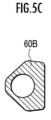
- the base end side portion 60B is made of a hard material having the same or equivalent hardness as the hard portion 20B of the inner tube 20.
- the engaged portion 61 is a wide rectangular protrusion that protrudes from the outer peripheral surface of the inner tube 20, but may have any shape as long as the engaged portion 61 can be engaged with the engaging portion 50.
- the main body portion 62 of the distal end side portion 60A has a donut-shaped cross section.
- the base end side portion 60B has a substantially triangular shape and a cross section having a circular hole at the top.
- the engaged portion 21 of the inner tube 20 is engaged and slid on the guide portion 30 extending in the axial direction from the distal end side to the proximal end side.
- the inner tube 20 can be smoothly inserted and pulled out while the position of the outer tube 30 relative to the inner tube 20 is maintained, and a desired treatment instrument can be used.
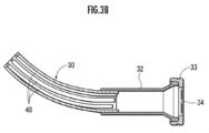
- the plurality of rail members 40 are each fixed to the hard part 30B on the most distal end side of the outer tube 30, so that the outer tube 30 is bent.
- each rail member 40 bends according to the bending of the outer tube 30 as shown in FIG. 3B. Therefore, it becomes possible to bend the outer tube 30 satisfactorily.
- the rail member 40 is made of a material harder than the soft portion 30A of the outer tube 30, the outer tube 30 can be easily bent at the soft portion 30A, and the inner peripheral surface of the outer tube 20 and the adjacent rail The shape of the engaging portion 50 formed between the member 40 and the member 40 can be ensured satisfactorily.
- the rail member 40 is fixed to the hard part 30B which is hard to deform
- the shape of the engaging part 50 formed between the inner peripheral surface of the outer tube 30 and the adjacent rail member 40 is formed. It becomes possible to ensure good.
- the soft material, the hard material, and the semi-hard material may be a material in which the softness is adjusted by changing the blend of the same type of resin.
- 10 Treatment instrument insertion aid, 20 ... Inner tube, 20A ... Soft part, 20B ... Hard part, 21 ... Engaged part, 30 ... Outer tube, 30A ... Soft part, 30B ... Hard part, 31 ... Guide part, 40 ... rail member, 41 ... guided portion, 50 ... engaging portion, 51 ... first wire member, 52 ... second wire member, 60 ... guide member, 61 ... engaged portion.
Landscapes
- Health & Medical Sciences (AREA)
- Life Sciences & Earth Sciences (AREA)
- Surgery (AREA)
- General Health & Medical Sciences (AREA)
- Public Health (AREA)
- Veterinary Medicine (AREA)
- Pathology (AREA)
- Nuclear Medicine, Radiotherapy & Molecular Imaging (AREA)
- Animal Behavior & Ethology (AREA)
- Engineering & Computer Science (AREA)
- Biomedical Technology (AREA)
- Heart & Thoracic Surgery (AREA)
- Medical Informatics (AREA)
- Molecular Biology (AREA)
- Biophysics (AREA)
- Physics & Mathematics (AREA)
- Radiology & Medical Imaging (AREA)
- Optics & Photonics (AREA)
- Endoscopes (AREA)
- Surgical Instruments (AREA)
- Instruments For Viewing The Inside Of Hollow Bodies (AREA)
Abstract
Description
Claims (3)
- 処置具の体内への挿入を補助する処置具挿入補助具であって、
可撓性を有し、内周面に円周方向に離間して先端側から基端側にかけて軸方向に延びる複数の案内部を有するアウターチューブと、
可撓性を有し、先端側から基端側にかけて軸方向に延び、前記案内部に係合される被案内部をそれぞれ有する複数のレール部材と、
可撓性を有し、前記アウターチューブの内周面と、隣接する前記レールとの間に形成される係合部に係合する被係合部を有するインナーチューブとを備え、
前記複数のレール部材は、それぞれ前記アウターチューブに1か所だけ固定されていることを特徴とする処置具挿入補助具。 - 請求項1記載の処置具挿入補助具において、
前記複数のレール部材は、前記アウターチューブの材料より硬質な材料からなることを特徴とする処置具挿入補助具。 - 請求項2記載の処置具挿入補助具において、
前記複数のレール部材が固定される前記アウターチューブの部分は、前記アウターチューブの他の部分の材料と比べて硬質な材料からなることを特徴とする処置具挿入補助具。
Priority Applications (7)
| Application Number | Priority Date | Filing Date | Title |
|---|---|---|---|
| JP2017504544A JP6525050B2 (ja) | 2015-03-12 | 2015-03-12 | 処置具挿入補助具 |
| SG11201707305PA SG11201707305PA (en) | 2015-03-12 | 2015-03-12 | Treatment-instrument insertion aid |
| US15/556,673 US11122964B2 (en) | 2015-03-12 | 2015-03-12 | Treatment-instrument insertion aid |
| PCT/JP2015/057389 WO2016143143A1 (ja) | 2015-03-12 | 2015-03-12 | 処置具挿入補助具 |
| MYPI2017703344A MY193202A (en) | 2015-03-12 | 2015-03-12 | Treatment-instrument insertion aid |
| EP15884630.3A EP3269289B1 (en) | 2015-03-12 | 2015-03-12 | Treatment-instrument insertion aid |
| TW104108268A TWI641355B (zh) | 2015-03-12 | 2015-03-13 | 處置具插入輔助具 |
Applications Claiming Priority (1)
| Application Number | Priority Date | Filing Date | Title |
|---|---|---|---|
| PCT/JP2015/057389 WO2016143143A1 (ja) | 2015-03-12 | 2015-03-12 | 処置具挿入補助具 |
Publications (1)
| Publication Number | Publication Date |
|---|---|
| WO2016143143A1 true WO2016143143A1 (ja) | 2016-09-15 |
Family
ID=56878554
Family Applications (1)
| Application Number | Title | Priority Date | Filing Date |
|---|---|---|---|
| PCT/JP2015/057389 Ceased WO2016143143A1 (ja) | 2015-03-12 | 2015-03-12 | 処置具挿入補助具 |
Country Status (7)
| Country | Link |
|---|---|
| US (1) | US11122964B2 (ja) |
| EP (1) | EP3269289B1 (ja) |
| JP (1) | JP6525050B2 (ja) |
| MY (1) | MY193202A (ja) |
| SG (1) | SG11201707305PA (ja) |
| TW (1) | TWI641355B (ja) |
| WO (1) | WO2016143143A1 (ja) |
Families Citing this family (2)
| Publication number | Priority date | Publication date | Assignee | Title |
|---|---|---|---|---|
| CN109985897A (zh) * | 2019-03-27 | 2019-07-09 | 南京贻润环境科技有限公司 | 一种用于地下水及土壤修复的水平反应井 |
| DE102020207365A1 (de) * | 2020-06-15 | 2021-12-16 | Siemens Healthcare Gmbh | Einfädelunterstützungseinrichtung zum Einfädeln eines Objektes in eine Führungsvorrichtung |
Citations (6)
| Publication number | Priority date | Publication date | Assignee | Title |
|---|---|---|---|---|
| JPS5689233A (en) * | 1979-12-24 | 1981-07-20 | Olympus Optical Co | Endoscope |
| JP2000037390A (ja) * | 1998-07-22 | 2000-02-08 | Olympus Optical Co Ltd | 内視鏡治療装置 |
| JP2000166936A (ja) * | 1998-12-09 | 2000-06-20 | Olympus Optical Co Ltd | 内視鏡治療装置 |
| JP2000325303A (ja) * | 1999-05-17 | 2000-11-28 | Olympus Optical Co Ltd | 内視鏡治療装置 |
| JP2004337617A (ja) * | 2003-05-16 | 2004-12-02 | Ethicon Endo Surgery Inc | 内視鏡用の医療装置およびガイドシステム |
| JP2012200552A (ja) * | 2011-03-28 | 2012-10-22 | Fujifilm Corp | 内視鏡用挿入補助具 |
Family Cites Families (10)
| Publication number | Priority date | Publication date | Assignee | Title |
|---|---|---|---|---|
| JP2602212B2 (ja) | 1985-09-30 | 1997-04-23 | オリンパス光学工業株式会社 | マルチルーメンチユーブ内視鏡 |
| DE19906191A1 (de) * | 1999-02-15 | 2000-08-17 | Ingo F Herrmann | Endoskop |
| US20070106113A1 (en) * | 2005-11-07 | 2007-05-10 | Biagio Ravo | Combination endoscopic operative delivery system |
| US7976458B2 (en) * | 2006-12-05 | 2011-07-12 | Ethicon Endo-Surgery, Inc. | Independent articulating accessory channel |
| US9254077B2 (en) * | 2007-04-02 | 2016-02-09 | Cook Medical Technologies Llc | Endoscopic apparatus having an outer rail |
| US9066655B2 (en) * | 2007-12-07 | 2015-06-30 | Ethicon Endo-Surgery, Inc. | Selective stiffening devices and methods |
| US8287469B2 (en) * | 2008-01-09 | 2012-10-16 | Ethicon Endo-Surgery, Inc. | Articulating surgical device and method of use |
| EP2337488B1 (en) * | 2008-07-18 | 2016-05-25 | Boston Scientific Scimed, Inc. | Endoscope with guide |
| HU229773B1 (hu) * | 2009-09-02 | 2014-06-30 | Eszköz sebészeti beavatkozáshoz | |
| WO2015029040A1 (en) * | 2013-08-31 | 2015-03-05 | Morena Medical Applications Ltd. | Endoscope with shared working channel |
-
2015
- 2015-03-12 SG SG11201707305PA patent/SG11201707305PA/en unknown
- 2015-03-12 MY MYPI2017703344A patent/MY193202A/en unknown
- 2015-03-12 EP EP15884630.3A patent/EP3269289B1/en active Active
- 2015-03-12 WO PCT/JP2015/057389 patent/WO2016143143A1/ja not_active Ceased
- 2015-03-12 US US15/556,673 patent/US11122964B2/en active Active
- 2015-03-12 JP JP2017504544A patent/JP6525050B2/ja active Active
- 2015-03-13 TW TW104108268A patent/TWI641355B/zh active
Patent Citations (6)
| Publication number | Priority date | Publication date | Assignee | Title |
|---|---|---|---|---|
| JPS5689233A (en) * | 1979-12-24 | 1981-07-20 | Olympus Optical Co | Endoscope |
| JP2000037390A (ja) * | 1998-07-22 | 2000-02-08 | Olympus Optical Co Ltd | 内視鏡治療装置 |
| JP2000166936A (ja) * | 1998-12-09 | 2000-06-20 | Olympus Optical Co Ltd | 内視鏡治療装置 |
| JP2000325303A (ja) * | 1999-05-17 | 2000-11-28 | Olympus Optical Co Ltd | 内視鏡治療装置 |
| JP2004337617A (ja) * | 2003-05-16 | 2004-12-02 | Ethicon Endo Surgery Inc | 内視鏡用の医療装置およびガイドシステム |
| JP2012200552A (ja) * | 2011-03-28 | 2012-10-22 | Fujifilm Corp | 内視鏡用挿入補助具 |
Non-Patent Citations (1)
| Title |
|---|
| See also references of EP3269289A4 * |
Also Published As
| Publication number | Publication date |
|---|---|
| MY193202A (en) | 2022-09-26 |
| JP6525050B2 (ja) | 2019-06-05 |
| US20180055337A1 (en) | 2018-03-01 |
| TW201632132A (zh) | 2016-09-16 |
| EP3269289B1 (en) | 2019-08-28 |
| JPWO2016143143A1 (ja) | 2017-12-21 |
| SG11201707305PA (en) | 2017-10-30 |
| EP3269289A4 (en) | 2018-03-21 |
| US11122964B2 (en) | 2021-09-21 |
| EP3269289A1 (en) | 2018-01-17 |
| TWI641355B (zh) | 2018-11-21 |
Similar Documents
| Publication | Publication Date | Title |
|---|---|---|
| JP6623462B2 (ja) | 処置具挿入補助具 | |
| JP3877075B2 (ja) | 内視鏡装置 | |
| CN102770061B (zh) | 插入辅助器械和内窥镜装置 | |
| US10493240B2 (en) | Steerable catheter handle | |
| JP6432019B2 (ja) | 処置具挿入補助具 | |
| JP2022512850A (ja) | 医用装置のための支持構造及びその製造方法 | |
| JP2011194126A (ja) | 内視鏡若しくは処置具のガイド管 | |
| JP6444809B2 (ja) | 内視鏡システム | |
| JP4648785B2 (ja) | 内視鏡用体内留置バルーンカテーテル | |
| JP6525050B2 (ja) | 処置具挿入補助具 | |
| JP2009056056A (ja) | 内視鏡案内管装置 | |
| JP2009056054A (ja) | 内視鏡案内管装置 | |
| CA2807476C (en) | Soft dual-layer rectal speculum | |
| JP6824507B2 (ja) | 内視鏡治療装置 | |
| JP6803691B2 (ja) | 可撓性穿刺針及び硬性鏡 | |
| JP2009089724A (ja) | 分離型内視鏡 | |
| JP2012192028A (ja) | オーバーチューブ | |
| JP7221482B2 (ja) | インナーチューブ | |
| JP2005230085A (ja) | バルーン付きオーバチューブ | |
| JP2009056055A (ja) | 内視鏡案内管装置 | |
| WO2017195348A1 (ja) | 医療用オーバーチューブ | |
| WO2016056416A1 (ja) | 内視鏡 | |
| JP2016220838A (ja) | 内視鏡用シース |
Legal Events
| Date | Code | Title | Description |
|---|---|---|---|
| 121 | Ep: the epo has been informed by wipo that ep was designated in this application |
Ref document number: 15884630 Country of ref document: EP Kind code of ref document: A1 |
|
| ENP | Entry into the national phase |
Ref document number: 2017504544 Country of ref document: JP Kind code of ref document: A |
|
| WWE | Wipo information: entry into national phase |
Ref document number: 11201707305P Country of ref document: SG |
|
| WWE | Wipo information: entry into national phase |
Ref document number: 15556673 Country of ref document: US |
|
| NENP | Non-entry into the national phase |
Ref country code: DE |
|
| REEP | Request for entry into the european phase |
Ref document number: 2015884630 Country of ref document: EP |