WO2016143213A1 - Dispositif de refroidissement - Google Patents
Dispositif de refroidissement Download PDFInfo
- Publication number
- WO2016143213A1 WO2016143213A1 PCT/JP2015/085034 JP2015085034W WO2016143213A1 WO 2016143213 A1 WO2016143213 A1 WO 2016143213A1 JP 2015085034 W JP2015085034 W JP 2015085034W WO 2016143213 A1 WO2016143213 A1 WO 2016143213A1
- Authority
- WO
- WIPO (PCT)
- Prior art keywords
- connection pipe
- refrigerant
- pipe
- cooling device
- connection
- Prior art date
- Legal status (The legal status is an assumption and is not a legal conclusion. Google has not performed a legal analysis and makes no representation as to the accuracy of the status listed.)
- Ceased
Links
Images



Classifications
-
- F—MECHANICAL ENGINEERING; LIGHTING; HEATING; WEAPONS; BLASTING
- F28—HEAT EXCHANGE IN GENERAL
- F28D—HEAT-EXCHANGE APPARATUS, NOT PROVIDED FOR IN ANOTHER SUBCLASS, IN WHICH THE HEAT-EXCHANGE MEDIA DO NOT COME INTO DIRECT CONTACT
- F28D15/00—Heat-exchange apparatus with the intermediate heat-transfer medium in closed tubes passing into or through the conduit walls ; Heat-exchange apparatus employing intermediate heat-transfer medium or bodies
- F28D15/02—Heat-exchange apparatus with the intermediate heat-transfer medium in closed tubes passing into or through the conduit walls ; Heat-exchange apparatus employing intermediate heat-transfer medium or bodies in which the medium condenses and evaporates, e.g. heat pipes
- F28D15/0266—Heat-exchange apparatus with the intermediate heat-transfer medium in closed tubes passing into or through the conduit walls ; Heat-exchange apparatus employing intermediate heat-transfer medium or bodies in which the medium condenses and evaporates, e.g. heat pipes with separate evaporating and condensing chambers connected by at least one conduit; Loop-type heat pipes; with multiple or common evaporating or condensing chambers
-
- F—MECHANICAL ENGINEERING; LIGHTING; HEATING; WEAPONS; BLASTING
- F28—HEAT EXCHANGE IN GENERAL
- F28D—HEAT-EXCHANGE APPARATUS, NOT PROVIDED FOR IN ANOTHER SUBCLASS, IN WHICH THE HEAT-EXCHANGE MEDIA DO NOT COME INTO DIRECT CONTACT
- F28D15/00—Heat-exchange apparatus with the intermediate heat-transfer medium in closed tubes passing into or through the conduit walls ; Heat-exchange apparatus employing intermediate heat-transfer medium or bodies
- F28D15/02—Heat-exchange apparatus with the intermediate heat-transfer medium in closed tubes passing into or through the conduit walls ; Heat-exchange apparatus employing intermediate heat-transfer medium or bodies in which the medium condenses and evaporates, e.g. heat pipes
-
- F—MECHANICAL ENGINEERING; LIGHTING; HEATING; WEAPONS; BLASTING
- F28—HEAT EXCHANGE IN GENERAL
- F28D—HEAT-EXCHANGE APPARATUS, NOT PROVIDED FOR IN ANOTHER SUBCLASS, IN WHICH THE HEAT-EXCHANGE MEDIA DO NOT COME INTO DIRECT CONTACT
- F28D15/00—Heat-exchange apparatus with the intermediate heat-transfer medium in closed tubes passing into or through the conduit walls ; Heat-exchange apparatus employing intermediate heat-transfer medium or bodies
- F28D15/02—Heat-exchange apparatus with the intermediate heat-transfer medium in closed tubes passing into or through the conduit walls ; Heat-exchange apparatus employing intermediate heat-transfer medium or bodies in which the medium condenses and evaporates, e.g. heat pipes
- F28D15/025—Heat-exchange apparatus with the intermediate heat-transfer medium in closed tubes passing into or through the conduit walls ; Heat-exchange apparatus employing intermediate heat-transfer medium or bodies in which the medium condenses and evaporates, e.g. heat pipes having non-capillary condensate return means
-
- H—ELECTRICITY
- H05—ELECTRIC TECHNIQUES NOT OTHERWISE PROVIDED FOR
- H05K—PRINTED CIRCUITS; CASINGS OR CONSTRUCTIONAL DETAILS OF ELECTRIC APPARATUS; MANUFACTURE OF ASSEMBLAGES OF ELECTRICAL COMPONENTS
- H05K7/00—Constructional details common to different types of electric apparatus
- H05K7/20—Modifications to facilitate cooling, ventilating, or heating
- H05K7/20536—Modifications to facilitate cooling, ventilating, or heating for racks or cabinets of standardised dimensions, e.g. electronic racks for aircraft or telecommunication equipment
- H05K7/20663—Liquid coolant with phase change, e.g. heat pipes
- H05K7/20672—Liquid coolant with phase change, e.g. heat pipes within sub-racks for removing heat from electronic boards
-
- H—ELECTRICITY
- H10—SEMICONDUCTOR DEVICES; ELECTRIC SOLID-STATE DEVICES NOT OTHERWISE PROVIDED FOR
- H10W—GENERIC PACKAGES, INTERCONNECTIONS, CONNECTORS OR OTHER CONSTRUCTIONAL DETAILS OF DEVICES COVERED BY CLASS H10
- H10W40/00—Arrangements for thermal protection or thermal control
- H10W40/70—Fillings or auxiliary members in containers or in encapsulations for thermal protection or control
- H10W40/73—Fillings or auxiliary members in containers or in encapsulations for thermal protection or control for cooling by change of state
-
- F—MECHANICAL ENGINEERING; LIGHTING; HEATING; WEAPONS; BLASTING
- F25—REFRIGERATION OR COOLING; COMBINED HEATING AND REFRIGERATION SYSTEMS; HEAT PUMP SYSTEMS; MANUFACTURE OR STORAGE OF ICE; LIQUEFACTION SOLIDIFICATION OF GASES
- F25B—REFRIGERATION MACHINES, PLANTS OR SYSTEMS; COMBINED HEATING AND REFRIGERATION SYSTEMS; HEAT PUMP SYSTEMS
- F25B23/00—Machines, plants or systems, with a single mode of operation not covered by groups F25B1/00 - F25B21/00, e.g. using selective radiation effect
- F25B23/006—Machines, plants or systems, with a single mode of operation not covered by groups F25B1/00 - F25B21/00, e.g. using selective radiation effect boiling cooling systems
-
- F—MECHANICAL ENGINEERING; LIGHTING; HEATING; WEAPONS; BLASTING
- F28—HEAT EXCHANGE IN GENERAL
- F28F—DETAILS OF HEAT-EXCHANGE AND HEAT-TRANSFER APPARATUS, OF GENERAL APPLICATION
- F28F2250/00—Arrangements for modifying the flow of the heat exchange media, e.g. flow guiding means; Particular flow patterns
- F28F2250/06—Derivation channels, e.g. bypass
-
- F—MECHANICAL ENGINEERING; LIGHTING; HEATING; WEAPONS; BLASTING
- F28—HEAT EXCHANGE IN GENERAL
- F28F—DETAILS OF HEAT-EXCHANGE AND HEAT-TRANSFER APPARATUS, OF GENERAL APPLICATION
- F28F2265/00—Safety or protection arrangements; Arrangements for preventing malfunction
- F28F2265/14—Safety or protection arrangements; Arrangements for preventing malfunction for preventing damage by freezing, e.g. for accommodating volume expansion
Definitions
- Embodiments of the present invention relate to a cooling device.
- Such a cooling device that cools a heating element using the heat of vaporization of a refrigerant.
- a cooling device includes an evaporation section in which the refrigerant is vaporized by heat generated by the heating element, a condensation section in which the evaporated refrigerant is condensed, a first connection pipe that guides the refrigerant vaporized in the evaporation section to the condensation section, A second connecting pipe for guiding the refrigerant condensed in the condensing unit to the evaporating unit;
- the diameter of the first connection pipe may not be sufficiently large due to installation space, piping cost, or other reasons.
- liquid refrigerant part of the liquid-phase refrigerant (hereinafter referred to as liquid refrigerant) in the evaporation unit is taken out to the first connection pipe and the condensing unit by the refrigerant vaporized in the evaporation unit. If this phenomenon continues for a certain amount of time, the liquid refrigerant may be depleted in the evaporating section, and the cooling performance of the cooling device may be reduced.
- the problem to be solved by the present invention is to provide a cooling device capable of suppressing a decrease in cooling efficiency.
- the cooling device of the embodiment includes an evaporation unit, a condensing unit, a first connection pipe, a second connection pipe, and a third connection pipe.
- the refrigerant is vaporized by the heat generated by the heating element.
- the condensing part is provided above the evaporation part, and the vaporized refrigerant is condensed by heat exchange with an external fluid.
- the first connecting pipe has a first end communicating with the evaporation unit and a second end communicating with the condensing unit, and guides the refrigerant vaporized in the evaporating unit to the condensing unit.
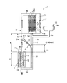
- Sectional drawing which shows the cooling device of embodiment typically. Sectional drawing which shows the connection part of the 3rd connecting pipe shown in FIG. 1, and a 1st connecting pipe. Sectional drawing which shows typically the mode at the time of the stop of the cooling device shown in FIG. Sectional drawing which shows typically the 1st modification of the cooling device shown in FIG. Sectional drawing which shows typically the 2nd modification of the cooling device shown in FIG. Sectional drawing which shows typically the 3rd modification of the cooling device shown in FIG. Sectional drawing which shows typically the 4th modification of the cooling device shown in FIG.
- FIG. 1 schematically shows a configuration example of the cooling device 1.
- the cooling device 1 is a thermosiphon type (two-phase thermosiphon type) cooling device.
- the cooling device 1 of the present embodiment includes an evaporation unit 2 that vaporizes the refrigerant, a condensation unit 3 that condenses the vaporized refrigerant, and a first connection pipe that guides the refrigerant vaporized in the evaporation unit 2 to the condensation unit 3. 4, a second connection pipe 5 that guides the refrigerant condensed in the condenser section 3 to the evaporation section 2, an expansion tank 6 connected to the second connection pipe 5, a part of the first connection pipe 4, and a second connection pipe 5 is provided with a third connecting pipe 7 connected to a part of 5.
- the evaporation unit 2 includes a case 11 and a space (storage unit, storage unit) 12 provided inside the case 11.
- the case 11 is formed of a material having good thermal conductivity such as metal.
- the case 11 is thermally connected to the heating element H to be cooled.
- the case 11 is arranged in the horizontal direction with respect to the heating element H.
- the surface of the case 11 (for example, the side surface 11a of the case 11) is in contact with the heating element H.
- the side surface 11a of the case 11 is formed to have substantially the same size as the main surface (surface having the largest area) of the heating element H.
- the heating element H has, for example, a plate-like outer shape.
- An example of the heating element H is a power amplifier that amplifies a radio signal for broadcasting output from a transmitter used in a broadcasting station or the like.
- the cooling device 1 of the present embodiment can be widely applied to various heating elements H.
- the heating element H to which the cooling device 1 can be applied is not particularly limited.
- the space 12 can accommodate a refrigerant.
- the refrigerant is put into the cooling device 1 so that the space portion 12 is sufficiently filled when the cooling device 1 is stopped.
- the type of the refrigerant is not particularly limited.
- the refrigerant is a fluid having a lower boiling point than water.
- the refrigerant is a fluid having a boiling point of about 50 ° C.
- the refrigerant receives heat generated by the heating element H in the evaporation unit 2. Thereby, a refrigerant
- coolant is vaporized in the evaporation part 2 and becomes a vapor
- the case 11 of this embodiment has a partition wall 11b between the heating element H and the space 12. For this reason, the refrigerant in the space portion 12 receives heat from the heating element H via the partition wall 11 b of the case 11.
- the case 11 may have an opening that opens toward the heating element H. That is, the refrigerant in the space 12 may directly contact the heating element H through the opening of the case 11.
- the evaporation unit 2 of the present embodiment is a so-called vertical type evaporation unit. That is, the horizontal width W1 of the space 12 in the direction in which the case 11 and the heating element H are arranged is smaller than the vertical width W2 of the space 12.
- the condensing unit 3 includes a plurality of cooling pipes 15, a plurality of fins 16 attached to the cooling pipes 15, and a fan 17 that sends air toward the cooling pipes 15 and the fins 16.
- each of the plurality of cooling pipes 15 extends in the vertical direction.
- the plurality of cooling pipes 15 are arranged in the horizontal direction.
- the inlets of the plurality of cooling pipes 15 are combined into one.
- the outlets of the plurality of cooling pipes 15 are combined into one.
- the plurality of fins 16 are respectively attached to the plurality of cooling pipes 15.
- the fan 17 sends wind toward the plurality of cooling pipes 15 and the plurality of fins 16. Thereby, the fan 17 cools the plurality of cooling pipes 15 and the plurality of fins 16.
- the condensing part 3 is provided above the evaporation part 2.
- the refrigerant evaporated in the evaporation unit 2 flows into the condensing unit 3.
- the refrigerant that has flowed into the condenser 3 is divided into a plurality of cooling pipes 15 and flows in.
- the refrigerant flowing into the cooling pipe 15 is condensed by exchanging heat with an external fluid (for example, air) via the cooling pipe 15 and the fins 16.
- the condensation part 3 is not limited to the said structure.
- the condensing unit 3 may be one that does not have the fan 17 (by natural air cooling), for example.
- the first connection pipe 4 communicates with the inlets of a plurality of cooling pipes 15 grouped together.
- the refrigerant vaporized by the evaporator 2 flows into the first connection pipe 4.
- the first connection pipe 4 guides the refrigerant evaporated in the evaporation unit 2 to the condensing unit 3.
- the second connecting pipe (liquid pipe) 5 is provided between the condensing unit 3 and the evaporating unit 2, and connects the condensing unit 3 and the evaporating unit 2.
- the second connecting pipe 5 has a first end 5a and a second end 5b.
- the first end 5 a of the second connecting pipe 5 is connected to the lower end of the condensing unit 3 and communicates with the condensing unit 3.
- the second connection pipe 5 communicates with the outlets of the plurality of cooling pipes 15 gathered together.
- the second end 5 b of the second connection pipe 5 is connected to the lower end of the evaporator 2 and communicates with the evaporator 2.
- the second connecting pipe 5 communicates with the lower end of the space 12 of the evaporation unit 2.
- the refrigerant condensed in the condensing unit 3 flows into the second connection pipe 5.
- the second connecting pipe 5 guides the refrigerant condensed in the condensing unit 3 to the evaporating unit 2.
- the second connection pipe 5 has a portion 5c located between the first end 5a and the second end 5b.
- the part 5 c of the second connection pipe 5 includes a descending pipe part 22 extending downward from the condensing part 3.
- the descending piping part 22 extends, for example, in a substantially vertical direction.
- the cooling device 1 includes a portion R in which the descending pipe part 22 of the second connection pipe 5 and the ascending pipe part 21 of the first connection pipe 4 extend substantially in parallel.
- the cooling device 1 of the present embodiment is a thermosiphon type cooling device. That is, the refrigerant condensed in the condensing unit 3 flows into the second connecting pipe 5 by gravity and returns to the evaporating unit 2. Thereby, the cooling device 1 can circulate a refrigerant
- the expansion tank 6 is an example of a “tank”.
- the expansion tank 6 includes a container 6a that can be expanded and contracted by fluctuations in atmospheric pressure, and an introduction pipe 6b that forms a connection port of the container 6a.
- the expansion tank 6 is connected to the second connection pipe 5.
- the expansion tank 6 is connected to the descending piping part 22 of the second connection pipe 5.
- connection position between the expansion tank 6 and the second connection pipe 5 is a position lower than the condensing unit 3.
- the connection position between the expansion tank 6 and the second connection pipe 5 is a position higher than the liquid level height H2 of the refrigerant in the second connection pipe 5. More specifically, the connection position between the expansion tank 6 and the second connection pipe 5 is a position higher than the maximum liquid level height H2max of the refrigerant in the second connection pipe 5 when the cooling device 1 is in operation.
- the expansion tank 6 can expand or contract in accordance with the atmospheric pressure in the second connection pipe 5 even when the refrigerant in the second connection pipe 5 reaches the maximum liquid level height H2max.
- “operation” in the present application means that the refrigerant circulates in the cooling device 1 through vaporization and condensation.
- the maximum liquid level height H2max of the refrigerant will be described later.
- the third connection pipe 7 is provided between the first connection pipe 4 and the second connection pipe 5.
- the third connecting pipe 7 includes a portion 4c located between the first end 4a and the second end 4b in the first connecting pipe 4, and a first end 5a and a second end in the second connecting pipe 5.
- the part 5c located between 5b is connected.
- One end of the third connection pipe 7 is connected to a part of the rising pipe part 21 of the first connection pipe 4.
- the other end of the third connection pipe 7 is connected to a part of the descending piping part 22 of the second connection pipe 5.
- the third connection pipe 7 connects the ascending pipe part 21 and the descending pipe part 22 at, for example, a portion R in which the ascending pipe part 21 and the descending pipe part 22 are arranged in parallel.
- the third connection pipe 7 extends between the ascending pipe part 21 and the descending pipe part 22 in a substantially horizontal direction.
- the 3rd connecting pipe 7 connects between the ascending piping part 21 and the descending piping part 22 in the shortest distance.
- a part of the liquid refrigerant in the evaporation unit 2 may be pushed up by the refrigerant evaporated in the evaporation unit 2.
- the third connection pipe 7 can cause at least a part of the liquid refrigerant pushed up into the first connection pipe 4 to flow from the first connection pipe 4 into the second connection pipe 5. That is, the third connection pipe 7 can cause at least a part of the liquid refrigerant pushed up into the first connection pipe 4 to flow into the second connection pipe 5 more quickly than when passing through the condensing unit 3.
- the liquid refrigerant flowing into the second connection pipe 5 through the third connection pipe 7 can return from the second connection pipe 5 to the evaporation unit 2.
- FIG. 2 shows a connection portion between the third connection pipe 7 and the first connection pipe 4.
- the liquid refrigerant pushed up into the first connection pipe 4 is pushed by the inner peripheral surface 21a of the ascending pipe portion 21 due to a large amount of refrigerant vapor, and is first attached while sticking to the inner peripheral surface 21a.
- the pipe 4 is raised.
- the inner peripheral surface 21 a of the rising pipe portion 21 is provided with an opening portion 21 b that opens in the radial direction of the first connecting pipe 4.
- the third connecting pipe 7 is connected to the opening 21b.
- the cooling device 1 when stopped, stores an amount of refrigerant that sufficiently fills the evaporation unit 2.
- the liquid level height H2 of the refrigerant in the second connection pipe 5 and the liquid level height H1 of the refrigerant in the first connection pipe 4 are balanced by gravity and are substantially the same height. It is in.
- the refrigerant is vaporized in the evaporating unit 2 when the cooling device 1 is in operation.
- the vaporization of the refrigerant during the low output operation is in a milder state than during the high output operation described later.
- the liquid refrigerant in the evaporation unit 2 is not pushed up to a relatively high position in the first connection pipe 4 by the refrigerant evaporated in the evaporation unit 2.
- the region N in the first connection pipe 4 is occupied by the refrigerant bubbles evaporated in the evaporation section 2.
- the substantial liquid level H1 of the refrigerant in the first connection pipe 4 is lower than when the cooling device 1 is stopped.
- the cooling device 1 due to the difference between the liquid level height H2 of the refrigerant in the second connection pipe 5 and the liquid level height H1 of the refrigerant in the first connection pipe 4, the cooling device 1 has the inside of the second connection pipe 5 A driving force for moving the refrigerant toward the evaporation unit 2 is generated.
- the cooling device 1 configured as described above, it is possible to suppress a decrease in cooling performance. That is, if the first connection pipe 4 is sufficiently thick in the cooling device 1, the liquid refrigerant in the evaporation unit 2 is hardly pushed up into the first connection pipe 4 by the vapor evaporated in the evaporation unit 2.
- the diameter of the first connection pipe 4 may not be sufficiently large due to installation space, piping cost, or other reasons. In such a case, a phenomenon occurs in which part of the liquid refrigerant in the evaporation unit 2 is taken out to the first connection pipe 4 and the condensation unit 3 by the vapor evaporated in the evaporation unit 2.
- the liquid refrigerant is depleted in the evaporation unit 2 and the cooling performance of the cooling device 1 may be reduced.
- the temperature of the evaporation unit 2 continues to rise beyond the boiling point of the refrigerant.
- the cooling device 1 of the present embodiment has the following configuration. That is, the cooling device 1 of the present embodiment includes the evaporation unit 2, the condensing unit 3, the first connection pipe 4, the second connection pipe 5, and the third connection pipe 7.
- the refrigerant is vaporized by the heat generated by the heating element H.
- the condensing part 3 is provided above the evaporation part 2, and the vaporized refrigerant condenses by heat exchange with an external fluid.
- the first connection pipe 4 guides the refrigerant evaporated in the evaporation unit 2 to the condensing unit 3.
- the second connecting pipe 5 guides the refrigerant condensed in the condensing unit 3 to the evaporating unit 2.
- the third connection pipe 7 connects the part 4 c of the first connection pipe 4 and the part 5 c of the second connection pipe 5.
- connection position between the third connection pipe 7 and the second connection pipe 5 may be a position lower than the liquid level height H2 of the refrigerant in the second connection pipe 5 as in the modification shown in FIG. .
- the connection position between the third connection pipe 7 and the second connection pipe 5 may be a position lower than the liquid level height H2 of the refrigerant in the second connection pipe 5 as in the modification shown in FIG. .
- at least a part of the liquid refrigerant pushed up into the first connection pipe 4 can be returned to the evaporator 2 by the third connection pipe 7.
- a part of the liquid refrigerant condensed in the condensing unit 3 and accumulated in the second connection pipe 5 also flows into the third connection pipe 7 from the second connection pipe 5.
- the connection position between the third connection pipe 7 and the second connection pipe 5 is at a position higher than at least the liquid level H2 of the refrigerant in the second connection pipe 5 when the cooling device 1 is stopped. is there.
- the liquid refrigerant that condenses in the condensing unit 3 and accumulates in the second connection pipe 5 has a liquid level height H2 in the second connection pipe 5 of at least the connection between the third connection pipe 7 and the second connection pipe 5. It does not flow into the third connecting pipe 7 until the position is reached. For this reason, liquid refrigerant tends to accumulate in the second connection pipe 5 up to a relatively high position.
- coolant within the cooling device 1 can be raised. Thereby, a liquid refrigerant can be returned to the evaporation part 2 more efficiently. As a result, a decrease in cooling performance of the cooling device 1 can be further suppressed.
- connection position of the third connection pipe 7 and the second connection pipe 5 is higher than the maximum liquid level height H2max of the refrigerant in the second connection pipe 5 during the operation of the cooling device 1. is there.
- a liquid refrigerant tends to accumulate to a higher position.
- the driving force for circulating the refrigerant in the cooling device 1 can be further increased.
- a decrease in cooling performance of the cooling device 1 can be further suppressed.
- the position of the 3rd connection pipe 7 with respect to the condensation part 3 is demonstrated.
- the connection position of the third connection pipe 7 and the second connection pipe 5 is at the same level as or higher than the condensation section 3, the third connection pipe 7 flows into the second connection pipe 5.
- the liquid refrigerant to flow into the condensing unit 3 from the second connection pipe 5.
- the function of the condensing unit 3 for condensing the vapor may be deteriorated.
- connection position of the third connection pipe 7 and the second connection pipe 5 is a position lower than the condensing unit 3. According to such a structure, it can suppress that the liquid refrigerant which flows in into the 2nd connection pipe 5 from the 3rd connection pipe 7 flows back into the condensation part 3.
- the position of the third connection pipe 7 with respect to the expansion tank 6 will be described. If the connection position between the third connection pipe 7 and the second connection pipe 5 is at the same level as or higher than the connection position between the second connection pipe 5 and the expansion tank 6, the third connection pipe 7 There is a possibility that the liquid refrigerant flowing into the second connecting pipe 5 flows into the expansion tank 6 from the second connecting pipe 5. When the liquid refrigerant flows into the expansion tank 6, there is a possibility that the operation of the expansion tank 6 that suppresses fluctuations in the atmospheric pressure in the second connection pipe 5 is weakened.
- connection position between the third connection pipe 7 and the second connection pipe 5 is lower than the connection position between the second connection pipe 5 and the expansion tank 6. According to this configuration, the liquid refrigerant flowing from the third connection pipe 7 into the second connection pipe 5 can be prevented from flowing into the expansion tank 6 from the second connection pipe 5. Thereby, the expansion tank 6 can be functioned more reliably.
- the expansion tank 6 may be provided below the third connection pipe 7.
- the inner diameter of the third connecting pipe 7 is equal to or less than the maximum inner diameter at which the vaporized refrigerant does not form a continuous phase in the third connecting pipe 7. According to such a configuration, it is possible to prevent the steam flowing in the first connection pipe 4 from excessively flowing into the third connection pipe 7. Thereby, most of the vapor evaporated in the evaporation unit 2 can be moved to the condensation unit 3. Thereby, the cooling function of the cooling device 1 can be maintained more reliably.
- the evaporation unit 2 has a space 12 that can accommodate the refrigerant.
- the first connecting pipe 4 communicates with the upper end portion of the space portion 12.
- the second connection pipe 5 communicates with the lower end portion of the space portion 12.
- the horizontal width W1 of the space portion 12 in the direction in which the heating elements H and the case 11 are arranged is smaller than the vertical width W2 of the space portion 12. That is, the evaporation unit 2 of the present embodiment is a vertical type evaporation unit. In the vertical type evaporation unit 2, since the area of the interface between the liquid phase and the gas phase is reduced inside the evaporation unit 2, the liquid refrigerant in the evaporation unit 2 is transferred to the first connection pipe 4 by the evaporated refrigerant.
- the third connection pipe 7 of the present embodiment is particularly effective in the cooling device 1 having such a vertically placed evaporation unit 2.
- the third connection pipe 7 of the present embodiment quickly causes the refrigerant pushed up into the first connection pipe 4 even in the cooling device 1 in which the horizontal width W1 of the space 12 is larger than the vertical width W2. By returning to the evaporation part 2, the fall of the cooling performance of the cooling device 1 can be suppressed.
- the first connecting pipe 4 has an inner peripheral surface 21a extending upward.
- the inner peripheral surface 21 a has an opening 21 b that opens in the radial direction of the first connection pipe 4 and is connected to the third connection pipe 7 at a position higher than the evaporation section 2.
- FIG. 4 schematically shows the cooling device 1 of the first modification.
- the position of the expansion tank 6 is different from that of the above embodiment.
- the other configurations of the present modification are the same as the configurations of the above-described embodiment. Therefore, the description of the same part as the above embodiment is omitted.
- the expansion tank 6 of this modification is connected to the first connection pipe 4.
- the expansion tank 6 can expand according to the atmospheric pressure in the first connection pipe 4.
- the connection position between the third connection pipe 7 and the first connection pipe 4 is a position lower than the connection position between the expansion tank 6 and the first connection pipe 4.
- the liquid refrigerant pushed up into the first connection pipe 4 can flow into the third connection pipe 7 before reaching the expansion tank 6. For this reason, it can suppress that the liquid refrigerant pushed up in the 1st connection pipe 4 flows in into the expansion tank 6. FIG. Thereby, the expansion tank 6 can be functioned more reliably.
- FIG. 5 schematically shows a cooling device 1 according to a second modification.
- the shape of the third connecting pipe 7 is different from that of the above embodiment.
- the other configurations of the present modification are the same as the configurations of the above-described embodiment. Therefore, the description of the same part as the above embodiment is omitted.
- the third connection pipe 7 of the present modification is inclined obliquely with respect to the horizontal direction. More specifically, the connection position between the third connection pipe 7 and the first connection pipe 4 is higher than the connection position between the third connection pipe 7 and the second connection pipe 5.
- the third connecting pipe 7 is inclined so as to be positioned downward as it proceeds from the first connecting pipe 4 toward the second connecting pipe 5.
- the connection position between the third connection pipe 7 and the first connection pipe 4 is the maximum liquid level of the refrigerant in the second connection pipe 5 during the operation of the cooling device 1 as in the above embodiment. It is above the height H2max.
- the liquid refrigerant that has flowed into the third connecting pipe 7 can flow into the second connecting pipe 5 more smoothly.
- the fall of the cooling performance of the cooling device 1 can further be suppressed.
- the third connection pipe 7 of this modification is inclined so as to be positioned downward as it proceeds from the first connection pipe 4 toward the second connection pipe 5, as in the second modification. is doing.
- the connection position of the 3rd connection pipe 7 and the 1st connection pipe 4 is a position higher than the maximum liquid level height H2max of the refrigerant
- the connection position between the third connection pipe 7 and the second connection pipe 5 is a position lower than the maximum liquid level height H2max of the refrigerant in the second connection pipe 5 during operation of the cooling device 1.
- the connection position between the third connection pipe 7 and the second connection pipe 5 may be a position lower than the liquid level height H2 in the second connection pipe 5 when the cooling device 1 is stopped.
- FIG. 7 schematically shows a cooling device 1 according to a fourth modification.
- the configuration of the evaporation unit 2 is different from that of the above embodiment.
- the other configurations of the present modification are the same as the configurations of the above-described embodiment. Therefore, the description of the same part as the above embodiment is omitted.
- each case 11 is a vertically placed type case as in the above embodiment. That is, in each case 11, the horizontal width W ⁇ b> 1 of the space portion 12 in the direction in which the heating element H and the case 11 are arranged is smaller than the vertical width W ⁇ b> 2 of the space portion 12.
- the first connection pipe 4 has a plurality of branch pipes 4 a divided into the same number as the plurality of cases 11. Each branch pipe 4 a communicates with the upper end of the space 12 of each case 11. The branch pipes 4a are connected to the plurality of cases 11 at substantially the same height.
- the plurality of branch pipes 4 a are an example of “first end portions” of the first connection pipe 4.
- the second connection pipe 5 has a plurality of branch pipes 5 b divided into the same number as the plurality of cases 11. Each branch pipe 5 b communicates with the lower end of the space 12 of each case 11.
- the branch pipes 5b are connected to the plurality of cases 11 at substantially the same height.
- the plurality of branch pipes 5 b are an example of “second end portions” of the second connection pipe 5.
- the liquid level height H2 of the refrigerant in the second connection pipe 5 and the liquid level height H1 of the refrigerant in the first connection pipe 4 with respect to the space portion 12 of the plurality of cases 11 The same driving force based on the difference can be applied.
- the refrigerant can cover the entire region of the heating element H even if the amount of the liquid refrigerant is reduced in the space 12 of the case 11. For this reason, when the case 11 is placed horizontally, the cooling performance is less likely to deteriorate due to the exhaustion of the refrigerant.
- the evaporation unit 2 includes a plurality of cases 11, the installation area is reduced by arranging a plurality of horizontally placed cases 11 in the vertical direction.
- the cooling device has an evaporation section, a condensing section, a first connection pipe, a second connection pipe, and a third connection pipe.
- the refrigerant is vaporized by the heat generated by the heating element.
- the condensing part is provided above the evaporation part, and the vaporized refrigerant is condensed by heat exchange with an external fluid.
- the first connecting pipe has a first end communicating with the evaporation unit and a second end communicating with the condensing unit, and guides the refrigerant vaporized in the evaporating unit to the condensing unit.
- H heating element, 1 ... cooling device, 2 ... evaporating part, 3 ... condensing part, 4 ... first connecting pipe, 5 ... second connecting pipe, 6 ... expansion tank, 7 ... third connecting pipe, 12 ... space part , W1... Horizontal width of the space portion, W2... Width of the space portion in the vertical direction, H2... Liquid level height of the refrigerant in the second connection pipe, H2max.
Landscapes
- Engineering & Computer Science (AREA)
- Physics & Mathematics (AREA)
- Thermal Sciences (AREA)
- Mechanical Engineering (AREA)
- General Engineering & Computer Science (AREA)
- Life Sciences & Earth Sciences (AREA)
- Sustainable Development (AREA)
- Aviation & Aerospace Engineering (AREA)
- Microelectronics & Electronic Packaging (AREA)
- Cooling Or The Like Of Electrical Apparatus (AREA)
- Cooling Or The Like Of Semiconductors Or Solid State Devices (AREA)
- Heat-Exchange Devices With Radiators And Conduit Assemblies (AREA)
Abstract
L'invention concerne, selon un mode de réalisation, un dispositif de refroidissement qui comporte un évaporateur, un condenseur, un premier tuyau de raccordement, un deuxième tuyau de raccordement et un troisième tuyau de raccordement. L'évaporateur vaporise un fluide frigorigène au moyen de la chaleur produite par un élément de chauffage. Le condenseur est prévu au-dessus de l'évaporateur, et le fluide frigorigène vaporisé est condensé par échange de chaleur avec un fluide externe. Le premier tuyau de raccordement guide le fluide frigorigène vaporisé par l'évaporateur vers le condenseur. Le deuxième tuyau de raccordement guide le fluide frigorigène condensé par le condenseur vers l'évaporateur. Le troisième tuyau de raccordement relie une partie du premier tuyau de raccordement et une partie du deuxième tuyau de raccordement. La position du raccord entre le troisième tuyau de raccordement et le premier tuyau de raccordement est plus élevée que le niveau maximal du fluide frigorigène dans le deuxième tuyau de raccordement en fonctionnement.
Priority Applications (2)
| Application Number | Priority Date | Filing Date | Title |
|---|---|---|---|
| CN201580077379.9A CN107532859A (zh) | 2015-03-06 | 2015-12-15 | 冷却装置 |
| US15/695,468 US10845127B2 (en) | 2015-03-06 | 2017-09-05 | Cooling device |
Applications Claiming Priority (2)
| Application Number | Priority Date | Filing Date | Title |
|---|---|---|---|
| JP2015-045166 | 2015-03-06 | ||
| JP2015045166A JP6605819B2 (ja) | 2015-03-06 | 2015-03-06 | 冷却装置 |
Related Child Applications (1)
| Application Number | Title | Priority Date | Filing Date |
|---|---|---|---|
| US15/695,468 Continuation US10845127B2 (en) | 2015-03-06 | 2017-09-05 | Cooling device |
Publications (1)
| Publication Number | Publication Date |
|---|---|
| WO2016143213A1 true WO2016143213A1 (fr) | 2016-09-15 |
Family
ID=56876738
Family Applications (1)
| Application Number | Title | Priority Date | Filing Date |
|---|---|---|---|
| PCT/JP2015/085034 Ceased WO2016143213A1 (fr) | 2015-03-06 | 2015-12-15 | Dispositif de refroidissement |
Country Status (4)
| Country | Link |
|---|---|
| US (1) | US10845127B2 (fr) |
| JP (1) | JP6605819B2 (fr) |
| CN (1) | CN107532859A (fr) |
| WO (1) | WO2016143213A1 (fr) |
Families Citing this family (16)
| Publication number | Priority date | Publication date | Assignee | Title |
|---|---|---|---|---|
| WO2016031186A1 (fr) * | 2014-08-27 | 2016-03-03 | 日本電気株式会社 | Dispositif de refroidissement à changement de phase, et procédé de refroidissement à changement de phase |
| WO2017051531A1 (fr) * | 2015-09-25 | 2017-03-30 | 日本電気株式会社 | Refroidisseur à changement de phase et son procédé de commande |
| US10260819B2 (en) * | 2016-07-26 | 2019-04-16 | Tokitae Llc | Thermosiphons for use with temperature-regulated storage devices |
| WO2018047532A1 (fr) * | 2016-09-09 | 2018-03-15 | 株式会社デンソー | Appareil de réglage de température de dispositif |
| CN109477696B (zh) * | 2016-09-09 | 2021-04-09 | 株式会社电装 | 设备温度调节装置 |
| CN109690222B (zh) * | 2016-09-09 | 2020-07-03 | 株式会社电装 | 设备温度调节装置 |
| JP6927229B2 (ja) * | 2016-09-21 | 2021-08-25 | 日本電気株式会社 | 相変化冷却装置および相変化冷却方法 |
| JP6784279B2 (ja) * | 2017-08-21 | 2020-11-11 | 株式会社デンソー | 機器温調装置 |
| JP2019052794A (ja) | 2017-09-14 | 2019-04-04 | 株式会社東芝 | 熱輸送装置 |
| JP2019082273A (ja) * | 2017-10-30 | 2019-05-30 | 下田 一喜 | 冷却システム |
| CN111163610B (zh) * | 2018-11-07 | 2021-08-10 | 英业达科技有限公司 | 冷却装置 |
| US11525636B2 (en) * | 2019-03-20 | 2022-12-13 | The Government Of The United States Of America, As Represented By The Secretary Of The Navy | Method and system for stabilizing loop heat pipe operation with a controllable condenser bypass |
| US11191190B2 (en) * | 2020-03-31 | 2021-11-30 | GM Cruise Holdings, LLC | Two-phase cooling systems for autonomous driving super computers |
| CN112736046B (zh) * | 2020-12-11 | 2024-03-22 | 杭州电子科技大学 | 一种集成芯片散热装置及其散热方法 |
| US11650015B2 (en) | 2021-08-09 | 2023-05-16 | Aavid Thermalloy, Llc | Method and apparatus for thermosiphon device |
| US11943904B2 (en) * | 2022-05-31 | 2024-03-26 | GE Grid GmbH | Hybrid thermosyphon with immersion cooled evaporator |
Citations (9)
| Publication number | Priority date | Publication date | Assignee | Title |
|---|---|---|---|---|
| JPS54131876A (en) * | 1978-04-05 | 1979-10-13 | Hitachi Ltd | Constant pressure type boiling cooler |
| JPS5681597U (fr) * | 1979-11-26 | 1981-07-01 | ||
| JPS6179773U (fr) * | 1984-10-29 | 1986-05-28 | ||
| JPH0323604U (fr) * | 1989-07-17 | 1991-03-12 | ||
| JPH09273876A (ja) * | 1996-04-08 | 1997-10-21 | Mitsubishi Denki Bill Techno Service Kk | 自然循環ループを備えた冷房装置 |
| JP2003318342A (ja) * | 2002-04-26 | 2003-11-07 | Japan Science & Technology Corp | 沸騰冷却方法および装置 |
| US20040037045A1 (en) * | 2002-08-14 | 2004-02-26 | Phillips Alfred L. | Thermal bus for electronics systems |
| WO2012144123A1 (fr) * | 2011-04-22 | 2012-10-26 | パナソニック株式会社 | Dispositif de refroidissement et véhicule électrique équipé de celui-ci |
| JP2014154683A (ja) * | 2013-02-07 | 2014-08-25 | Toshiba Corp | 冷却装置 |
Family Cites Families (20)
| Publication number | Priority date | Publication date | Assignee | Title |
|---|---|---|---|---|
| US958795A (en) * | 1909-12-02 | 1910-05-24 | Art Metal Construction Co | Door-frame. |
| JPS51116447A (en) * | 1975-04-07 | 1976-10-13 | Hitachi Ltd | A heat conducting device |
| JPS53122161A (en) * | 1977-03-31 | 1978-10-25 | Hitachi Ltd | Boiling cooler |
| JPS5430552A (en) * | 1977-08-12 | 1979-03-07 | Hitachi Ltd | Boiling cooling apparatus |
| JPS5651848A (en) * | 1979-10-05 | 1981-05-09 | Hitachi Ltd | Condenser for boiling type cooling device |
| JPS56135949A (en) * | 1980-03-28 | 1981-10-23 | Hitachi Ltd | Cooling device by boiling |
| SU958795A2 (ru) * | 1981-02-02 | 1982-09-15 | Киевский Ордена Ленина Политехнический Институт Им.50-Летия Великой Октябрьской Социалистической Революции | Отопительный радиатор |
| JPS5994445A (ja) * | 1982-11-20 | 1984-05-31 | Mitsubishi Electric Corp | 自然循環式沸騰冷却装置 |
| JP3908369B2 (ja) | 1997-12-29 | 2007-04-25 | 株式会社フジクラ | 熱駆動型冷却装置 |
| JPH11325766A (ja) * | 1998-05-20 | 1999-11-26 | Denso Corp | 沸騰冷却装置 |
| CN1330922C (zh) * | 2002-01-22 | 2007-08-08 | 汉尼·迪那 | 具有泵辅助的热管回路 |
| US7823629B2 (en) * | 2003-03-20 | 2010-11-02 | Thermal Corp. | Capillary assisted loop thermosiphon apparatus |
| EP1702360A2 (fr) | 2003-12-08 | 2006-09-20 | Noise Limit ApS | Systeme de refroidissement a pompe a bulles |
| RU2007129729A (ru) | 2005-01-03 | 2009-02-10 | НОЙЗ ЛИМИТ АпС (DK) | Многоориентационная система охлаждения с пузырьковым насосом |
| JP2007333293A (ja) | 2006-06-14 | 2007-12-27 | Denso Corp | ループ式ヒートパイプ |
| CN1995896A (zh) * | 2007-01-08 | 2007-07-11 | 刘海云 | 两维循环重力热管 |
| JP2012241976A (ja) | 2011-05-19 | 2012-12-10 | Fujikura Ltd | ループ型ヒートパイプ |
| EP2703763A1 (fr) * | 2012-09-03 | 2014-03-05 | ABB Technology AG | Évaporateur avec préchauffage intégré pour refroidissement des dispositifs électroniques d'alimentation |
| CN103968573A (zh) * | 2013-01-28 | 2014-08-06 | 大厂菲斯曼太阳能集热器有限公司 | 一种真空式太阳能热水系统的热传输方法、系统及其制造方法 |
| FR3002028B1 (fr) | 2013-02-14 | 2017-06-02 | Euro Heat Pipes | Dispositif de transport de chaleur a fluide diphasique |
-
2015
- 2015-03-06 JP JP2015045166A patent/JP6605819B2/ja active Active
- 2015-12-15 WO PCT/JP2015/085034 patent/WO2016143213A1/fr not_active Ceased
- 2015-12-15 CN CN201580077379.9A patent/CN107532859A/zh active Pending
-
2017
- 2017-09-05 US US15/695,468 patent/US10845127B2/en active Active
Patent Citations (9)
| Publication number | Priority date | Publication date | Assignee | Title |
|---|---|---|---|---|
| JPS54131876A (en) * | 1978-04-05 | 1979-10-13 | Hitachi Ltd | Constant pressure type boiling cooler |
| JPS5681597U (fr) * | 1979-11-26 | 1981-07-01 | ||
| JPS6179773U (fr) * | 1984-10-29 | 1986-05-28 | ||
| JPH0323604U (fr) * | 1989-07-17 | 1991-03-12 | ||
| JPH09273876A (ja) * | 1996-04-08 | 1997-10-21 | Mitsubishi Denki Bill Techno Service Kk | 自然循環ループを備えた冷房装置 |
| JP2003318342A (ja) * | 2002-04-26 | 2003-11-07 | Japan Science & Technology Corp | 沸騰冷却方法および装置 |
| US20040037045A1 (en) * | 2002-08-14 | 2004-02-26 | Phillips Alfred L. | Thermal bus for electronics systems |
| WO2012144123A1 (fr) * | 2011-04-22 | 2012-10-26 | パナソニック株式会社 | Dispositif de refroidissement et véhicule électrique équipé de celui-ci |
| JP2014154683A (ja) * | 2013-02-07 | 2014-08-25 | Toshiba Corp | 冷却装置 |
Also Published As
| Publication number | Publication date |
|---|---|
| US20170363365A1 (en) | 2017-12-21 |
| CN107532859A (zh) | 2018-01-02 |
| JP6605819B2 (ja) | 2019-11-13 |
| JP2016164478A (ja) | 2016-09-08 |
| US10845127B2 (en) | 2020-11-24 |
Similar Documents
| Publication | Publication Date | Title |
|---|---|---|
| JP6605819B2 (ja) | 冷却装置 | |
| JP6137167B2 (ja) | 冷却装置および冷却システム | |
| JP6423221B2 (ja) | 蒸発器及び冷凍機 | |
| JP6285356B2 (ja) | 沸騰冷却装置 | |
| EP3091321A1 (fr) | Dispositif de distribution de fluide frigorigène et dispositif de refroidissement | |
| CN107850359A (zh) | 蒸发器及具备该蒸发器的涡轮制冷装置 | |
| JP2012241976A (ja) | ループ型ヒートパイプ | |
| JP6927229B2 (ja) | 相変化冷却装置および相変化冷却方法 | |
| US9903659B2 (en) | Low pressure chiller | |
| CN105904960A (zh) | 冷却模块 | |
| KR102266037B1 (ko) | 수동 2-상 쿨링 회로 | |
| JP6678235B2 (ja) | 熱交換器 | |
| JP2010050326A (ja) | 冷却装置 | |
| WO2016159056A1 (fr) | Dispositif de distribution de milieu thermique et procédé de distribution de milieu thermique | |
| JP2010236792A (ja) | 沸騰冷却装置 | |
| WO2017110740A1 (fr) | Dispositif de dissipation de chaleur, dispositif de refroidissement à changement de phase dans lequel celui-ci est utilisé, et procédé de dissipation de chaleur | |
| WO2017203973A1 (fr) | Dispositif de production d'énergie thermoélectrique | |
| JP6597074B2 (ja) | 冷却システム | |
| JP2012220081A (ja) | 凝縮器、及びこれを備えた凝縮システム | |
| US10631434B2 (en) | Self-priming thermosyphon | |
| WO2016031186A1 (fr) | Dispositif de refroidissement à changement de phase, et procédé de refroidissement à changement de phase | |
| JP2016133287A (ja) | ループ型ヒートパイプ | |
| JP6801665B2 (ja) | 相変化冷却装置およびその制御方法 | |
| JP2017106710A (ja) | 吸収式冷凍機 | |
| JP2010223463A (ja) | 沸騰冷却装置 |
Legal Events
| Date | Code | Title | Description |
|---|---|---|---|
| 121 | Ep: the epo has been informed by wipo that ep was designated in this application |
Ref document number: 15884697 Country of ref document: EP Kind code of ref document: A1 |
|
| NENP | Non-entry into the national phase |
Ref country code: DE |
|
| 122 | Ep: pct application non-entry in european phase |
Ref document number: 15884697 Country of ref document: EP Kind code of ref document: A1 |