WO2016143264A1 - 燃料噴射装置 - Google Patents
燃料噴射装置 Download PDFInfo
- Publication number
- WO2016143264A1 WO2016143264A1 PCT/JP2016/000797 JP2016000797W WO2016143264A1 WO 2016143264 A1 WO2016143264 A1 WO 2016143264A1 JP 2016000797 W JP2016000797 W JP 2016000797W WO 2016143264 A1 WO2016143264 A1 WO 2016143264A1
- Authority
- WO
- WIPO (PCT)
- Prior art keywords
- fuel
- outer peripheral
- injection device
- fuel injection
- pressure
- Prior art date
- Legal status (The legal status is an assumption and is not a legal conclusion. Google has not performed a legal analysis and makes no representation as to the accuracy of the status listed.)
- Ceased
Links
Images


Classifications
-
- F—MECHANICAL ENGINEERING; LIGHTING; HEATING; WEAPONS; BLASTING
- F02—COMBUSTION ENGINES; HOT-GAS OR COMBUSTION-PRODUCT ENGINE PLANTS
- F02M—SUPPLYING COMBUSTION ENGINES IN GENERAL WITH COMBUSTIBLE MIXTURES OR CONSTITUENTS THEREOF
- F02M55/00—Fuel-injection apparatus characterised by their fuel conduits or their venting means; Arrangements of conduits between fuel tank and pump F02M37/00
- F02M55/002—Arrangement of leakage or drain conduits in or from injectors
-
- F—MECHANICAL ENGINEERING; LIGHTING; HEATING; WEAPONS; BLASTING
- F02—COMBUSTION ENGINES; HOT-GAS OR COMBUSTION-PRODUCT ENGINE PLANTS
- F02M—SUPPLYING COMBUSTION ENGINES IN GENERAL WITH COMBUSTIBLE MIXTURES OR CONSTITUENTS THEREOF
- F02M47/00—Fuel-injection apparatus operated cyclically with fuel-injection valves actuated by fluid pressure
-
- F—MECHANICAL ENGINEERING; LIGHTING; HEATING; WEAPONS; BLASTING
- F02—COMBUSTION ENGINES; HOT-GAS OR COMBUSTION-PRODUCT ENGINE PLANTS
- F02M—SUPPLYING COMBUSTION ENGINES IN GENERAL WITH COMBUSTIBLE MIXTURES OR CONSTITUENTS THEREOF
- F02M47/00—Fuel-injection apparatus operated cyclically with fuel-injection valves actuated by fluid pressure
- F02M47/02—Fuel-injection apparatus operated cyclically with fuel-injection valves actuated by fluid pressure of accumulator-injector type, i.e. having fuel pressure of accumulator tending to open, and fuel pressure in other chamber tending to close, injection valves and having means for periodically releasing that closing pressure
-
- F—MECHANICAL ENGINEERING; LIGHTING; HEATING; WEAPONS; BLASTING
- F02—COMBUSTION ENGINES; HOT-GAS OR COMBUSTION-PRODUCT ENGINE PLANTS
- F02M—SUPPLYING COMBUSTION ENGINES IN GENERAL WITH COMBUSTIBLE MIXTURES OR CONSTITUENTS THEREOF
- F02M47/00—Fuel-injection apparatus operated cyclically with fuel-injection valves actuated by fluid pressure
- F02M47/02—Fuel-injection apparatus operated cyclically with fuel-injection valves actuated by fluid pressure of accumulator-injector type, i.e. having fuel pressure of accumulator tending to open, and fuel pressure in other chamber tending to close, injection valves and having means for periodically releasing that closing pressure
- F02M47/027—Electrically actuated valves draining the chamber to release the closing pressure
-
- F—MECHANICAL ENGINEERING; LIGHTING; HEATING; WEAPONS; BLASTING
- F02—COMBUSTION ENGINES; HOT-GAS OR COMBUSTION-PRODUCT ENGINE PLANTS
- F02M—SUPPLYING COMBUSTION ENGINES IN GENERAL WITH COMBUSTIBLE MIXTURES OR CONSTITUENTS THEREOF
- F02M55/00—Fuel-injection apparatus characterised by their fuel conduits or their venting means; Arrangements of conduits between fuel tank and pump F02M37/00
- F02M55/004—Joints; Sealings
-
- F—MECHANICAL ENGINEERING; LIGHTING; HEATING; WEAPONS; BLASTING
- F02—COMBUSTION ENGINES; HOT-GAS OR COMBUSTION-PRODUCT ENGINE PLANTS
- F02M—SUPPLYING COMBUSTION ENGINES IN GENERAL WITH COMBUSTIBLE MIXTURES OR CONSTITUENTS THEREOF
- F02M55/00—Fuel-injection apparatus characterised by their fuel conduits or their venting means; Arrangements of conduits between fuel tank and pump F02M37/00
- F02M55/007—Venting means
-
- F—MECHANICAL ENGINEERING; LIGHTING; HEATING; WEAPONS; BLASTING
- F02—COMBUSTION ENGINES; HOT-GAS OR COMBUSTION-PRODUCT ENGINE PLANTS
- F02M—SUPPLYING COMBUSTION ENGINES IN GENERAL WITH COMBUSTIBLE MIXTURES OR CONSTITUENTS THEREOF
- F02M55/00—Fuel-injection apparatus characterised by their fuel conduits or their venting means; Arrangements of conduits between fuel tank and pump F02M37/00
- F02M55/008—Arrangement of fuel passages inside of injectors
-
- F—MECHANICAL ENGINEERING; LIGHTING; HEATING; WEAPONS; BLASTING
- F02—COMBUSTION ENGINES; HOT-GAS OR COMBUSTION-PRODUCT ENGINE PLANTS
- F02M—SUPPLYING COMBUSTION ENGINES IN GENERAL WITH COMBUSTIBLE MIXTURES OR CONSTITUENTS THEREOF
- F02M61/00—Fuel-injectors not provided for in groups F02M39/00 - F02M57/00 or F02M67/00
- F02M61/04—Fuel-injectors not provided for in groups F02M39/00 - F02M57/00 or F02M67/00 having valves, e.g. having a plurality of valves in series
-
- F—MECHANICAL ENGINEERING; LIGHTING; HEATING; WEAPONS; BLASTING
- F02—COMBUSTION ENGINES; HOT-GAS OR COMBUSTION-PRODUCT ENGINE PLANTS
- F02M—SUPPLYING COMBUSTION ENGINES IN GENERAL WITH COMBUSTIBLE MIXTURES OR CONSTITUENTS THEREOF
- F02M61/00—Fuel-injectors not provided for in groups F02M39/00 - F02M57/00 or F02M67/00
- F02M61/16—Details not provided for in, or of interest apart from, the apparatus of groups F02M61/02 - F02M61/14
-
- F—MECHANICAL ENGINEERING; LIGHTING; HEATING; WEAPONS; BLASTING
- F02—COMBUSTION ENGINES; HOT-GAS OR COMBUSTION-PRODUCT ENGINE PLANTS
- F02M—SUPPLYING COMBUSTION ENGINES IN GENERAL WITH COMBUSTIBLE MIXTURES OR CONSTITUENTS THEREOF
- F02M61/00—Fuel-injectors not provided for in groups F02M39/00 - F02M57/00 or F02M67/00
- F02M61/16—Details not provided for in, or of interest apart from, the apparatus of groups F02M61/02 - F02M61/14
- F02M61/18—Injection nozzles, e.g. having valve seats; Details of valve member seated ends, not otherwise provided for
-
- F—MECHANICAL ENGINEERING; LIGHTING; HEATING; WEAPONS; BLASTING
- F02—COMBUSTION ENGINES; HOT-GAS OR COMBUSTION-PRODUCT ENGINE PLANTS
- F02M—SUPPLYING COMBUSTION ENGINES IN GENERAL WITH COMBUSTIBLE MIXTURES OR CONSTITUENTS THEREOF
- F02M2200/00—Details of fuel-injection apparatus, not otherwise provided for
- F02M2200/70—Linkage between actuator and actuated element, e.g. between piezoelectric actuator and needle valve or pump plunger
- F02M2200/703—Linkage between actuator and actuated element, e.g. between piezoelectric actuator and needle valve or pump plunger hydraulic
- F02M2200/708—Linkage between actuator and actuated element, e.g. between piezoelectric actuator and needle valve or pump plunger hydraulic with hydraulic chambers formed by a movable sleeve
Definitions
- the present disclosure relates to a fuel injection device that injects fuel supplied to a combustion chamber of an internal combustion engine.
- a fuel injection device including a nozzle body, a nozzle needle, and a cylinder is known.
- the nozzle needle moves in the axial direction inside the nozzle body by the pressure of the fuel introduced into the pressure control chamber partitioned by the cylinder. Accordingly, the nozzle needle is separated from and seated on the seat portion formed on the nozzle body, so that the fuel injection from the injection hole is started and stopped.
- the nozzle body needs to be processed to form a sheet portion.
- the processing of the seat portion is performed by inserting a tool into a fuel passage formed in the nozzle body.
- the nozzle body surrounds the outer peripheral side of the cylinder, when the pressure control chamber and the cylinder are expanded in the axial direction as the stroke is extended, the nozzle body is also expanded in the axial direction.
- the processing accuracy may be deteriorated.
- An object of the present disclosure is to provide a fuel injection device capable of extending a stroke while maintaining processing accuracy of a seat portion.
- a fuel injection device is a fuel injection device that injects fuel supplied to a combustion chamber of an internal combustion engine from an injection hole, a fuel passage through which fuel flows and a seat portion facing the fuel passage
- a valve body that moves along the axial direction of the valve body inside the valve body, opens and closes the nozzle hole by being seated on and off the seat portion, and the nozzle hole across the valve member
- a partition member that divides the pressure control chamber that controls the movement of the valve member by the pressure of the introduced fuel, and an outer peripheral member that surrounds the outer peripheral side of the partition member and forms a fuel passage together with the valve body And.
- an outer peripheral member that forms a fuel passage through which fuel flows through the nozzle hole together with the valve body surrounds the outer peripheral side of the partition member that partitions the pressure control chamber. Therefore, even if the pressure control chamber and the partition member are expanded in the axial direction as the stroke of the valve member is extended, the physique of the valve body can be maintained by the expansion of the outer peripheral member in the axial direction. Therefore, it is possible to ensure the stroke amount of the valve member while suppressing deterioration in processing accuracy when forming the seat portion on the valve body.
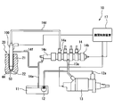
- the drawing 1 is a diagram illustrating an overall configuration of a fuel supply system to which a fuel injection device according to an embodiment of the present disclosure is applied; It is a longitudinal sectional view of the fuel injection device, It is the figure which expanded the control body of the fuel injection device, It is an enlarged view of the spacer and its vicinity, FIG. 5 is a plan view of a spacer and the like seen in the direction of arrow V in FIG. It is a figure which shows the modification of FIG.
- a fuel injection device 100 is used in the fuel supply system 10 illustrated in FIG.
- the fuel supply system 10 supplies fuel to a combustion chamber 22 of a diesel engine 20 that is an internal combustion engine by a fuel injection device 100.
- the fuel supply system 10 includes a feed pump 12, a high-pressure fuel pump 13, a common rail 14, an engine control device 17, a fuel injection device 100, and the like.
- the feed pump 12 is an electric pump housed in the fuel tank 11.
- the feed pump 12 applies a feed pressure higher than the vapor pressure of the fuel to the fuel such as light oil stored in the fuel tank 11.
- the feed pump 12 is connected to the high-pressure fuel pump 13 by a fuel pipe 12a.
- the feed pump 12 supplies the high-pressure fuel pump 13 with fuel in a liquid phase state given a predetermined feed pressure.
- the high-pressure fuel pump 13 is attached to the diesel engine 20 and is driven by the output shaft of the diesel engine.
- the high-pressure fuel pump 13 is connected to the common rail 14 by a fuel pipe 13a.
- the high-pressure fuel pump 13 further increases the pressure of the fuel supplied by the feed pump 12 to produce high-pressure fuel to be supplied to the common rail 14.
- the high-pressure fuel pump 13 has a solenoid valve that is electrically connected to the engine control device 17. The opening / closing of the solenoid valve is controlled by the engine control device 17, whereby the pressure of the fuel supplied from the high-pressure fuel pump 13 to the common rail 14 is adjusted to a predetermined pressure.
- the common rail 14 is a tubular member made of a metal material such as chromium molybdenum steel.
- the common rail 14 is formed with a plurality of branch portions 14a corresponding to the number of cylinders of the diesel engine. Each branch portion 14a is connected to one of the plurality of fuel injection devices 100 by a fuel pipe 14d.
- the common rail 14 temporarily stores the high-pressure fuel supplied from the high-pressure fuel pump 13 and distributes the high-pressure fuel to the plurality of fuel injection devices 100 while maintaining the pressure.
- the common rail 14 is provided with a common rail sensor 14b and a pressure regulator 14c.
- the common rail sensor 14 b is electrically connected to the engine control device 17, detects the pressure and temperature of the fuel, and outputs it to the engine control device 17.
- the pressure regulator 14 c is attached to the end of the common rail 14.
- the pressure regulator 14c keeps the fuel pressure in the common rail 14 constant, and depressurizes the excess fuel and discharges it to the low pressure side. Excess fuel discharged from the pressure regulator 14 c is returned to the fuel tank 11 through the fuel pipe 14 e connecting the common rail 14 and the fuel tank 11.
- the engine control device 17 includes a processor as an arithmetic circuit, a RAM, a microcomputer including a rewritable nonvolatile storage medium, and the like.
- the engine control device 17 is electrically connected to various sensors such as a rotation speed sensor that detects the rotation speed of the diesel engine 20 in addition to the common rail sensor 14b. Based on information from each of these sensors, the engine control device 17 sends a control signal for controlling the solenoid valve of the high pressure fuel pump 13 and the valve mechanism of each fuel injection device 100 to the high pressure fuel pump 13 and each fuel injection. Output to the device 100.
- the fuel injection device 100 directly injects fuel into the combustion chamber 22.
- the fuel injection device 100 is attached to the head member 21 in a state of being inserted into an insertion hole of the head member 21 that forms the combustion chamber 22 of the diesel engine 20.
- the fuel injection device 100 injects the high-pressure fuel supplied from the fuel pipe 14 d into the combustion chamber 22 through the injection hole 44.
- the injection pressure of the fuel injection device 100 is about 160 to 250 megapascals (MPa).
- the fuel injection device 100 includes a valve mechanism that controls injection of high-pressure fuel from the injection hole 44.
- the valve mechanism includes a pressure control valve 35 (see FIG. 2 and the like) that operates based on a control signal from the engine control device 17, and a main valve portion 50 that opens and closes the injection hole 44.
- the fuel injection device 100 uses part of the high-pressure fuel supplied from the fuel pipe 14d in order to open and close the injection hole 44. Such fuel is discharged to the fuel pipe 14f on the low pressure side and returned to the fuel tank 11 through the fuel
- the fuel injection device 100 includes a drive unit 30, a control body 40, a nozzle needle 60, and a floating plate 70 as shown in FIG.
- the drive unit 30 is accommodated in the control body 40.
- the drive unit 30 is connected to the control valve face member 33.
- the control valve face member 33 forms a pressure control valve 35 together with the control seat portion 46a.
- a pulse-like control signal is supplied from the engine control device 17 to the drive unit 30.
- the drive unit 30 opens and closes the pressure control valve 35 by displacing the control valve face member 33 based on the control signal.
- the drive unit 30 seats the control valve face member 33 on the control seat unit 46a.
- the pressure control valve 35 is closed.
- the drive unit 30 separates the control valve face member 33 from the control seat unit 46a.
- the pressure control valve 35 is opened.
- the control body 40 forms a nozzle hole 44, an inflow passage 52, an outflow passage 54, a supply passage 55, and a pressure control chamber 53.
- the injection hole 44 is formed at the distal end in the insertion direction of the control body 40 inserted into the combustion chamber 22 (see FIG. 1).
- the tip is formed in a conical or hemispherical shape.
- a plurality of nozzle holes 44 are provided radially from the inside to the outside of the control body 40. High-pressure fuel is injected into the combustion chamber 22 through the injection hole 44. By passing through the nozzle hole 44, the high-pressure fuel is atomized and diffused to be easily mixed with air.
- the first passage end of the inflow passage 52 is connected to the vertical hole 48a.
- the second passage end of the inflow passage 52 is connected to the pressure control chamber 53.
- the inflow passage 52 allows high-pressure fuel supplied through the fuel pipe 14 d (see FIG. 1) and the vertical hole 48 a to flow into the pressure control chamber 53.
- the first passage end of the outflow passage 54 is connected to the pressure control valve 35.
- the second passage end of the outflow passage 54 is connected to the pressure control chamber 53.
- the outflow passage 54 causes the fuel in the pressure control chamber 53 to flow out to the fuel pipe 14f (see FIG. 1) by opening the pressure control valve 35.
- the supply passage 55 is branched from the inflow passage 52 inside the control body 40.
- the supply passage 55 is formed in a cylindrical hole shape across a plurality of members forming the control body 40.
- the supply passage 55 allows the fuel pipe 14d (see FIG. 1) and the injection hole 44 to communicate with each other.
- the supply passage 55 allows high-pressure fuel supplied through the fuel pipe 14 d to flow through the nozzle hole 44.
- the pressure control chamber 53 is located inside the control body 40 on the opposite side of the nozzle hole 44 with the nozzle needle 60 interposed therebetween.
- the pressure control chamber 53 varies the pressure by inflow of high-pressure fuel from the inflow passage 52 and outflow of fuel through the outflow passage 54. Using such fuel pressure, the pressure control chamber 53 controls the movement of the nozzle needle 60.
- the control body 40 includes a nozzle body 41, a cylinder 56, an orifice plate 46, a holder 48, a retaining nut 49, a spacer 80, and the like.
- the nozzle body 41, the spacer 80, the orifice plate 46, and the holder 48 are arranged in this order from the front end side in the direction of insertion into the head member 21 (see FIG. 1).
- the nozzle body 41 is a bottomed cylindrical member formed of a metal material such as chromium molybdenum steel.
- the nozzle body 41 is formed with a nozzle hole 44 and a part of the supply passage 55.
- the nozzle body 41 has a nozzle needle housing chamber 43 and a seat portion 45.
- the nozzle needle storage chamber 43 is a cylindrical hole whose outer peripheral side is partitioned by the peripheral wall 43a.
- the nozzle needle storage chamber 43 stores the nozzle needle 60.
- the nozzle needle storage chamber 43 is formed along the axial direction of the nozzle body 41.
- the nozzle needle housing chamber 43 is open on the end surface of the nozzle body 41 on the orifice plate 46 side.
- the nozzle needle housing chamber 43 forms a supply passage 55.
- the sheet portion 45 is formed in a conical shape by the inner peripheral wall of the nozzle body 41 facing the supply passage 55.
- the sheet portion 45 is located inside the tip portion and contacts the tip of the nozzle needle 60.
- the sheet portion 45 is machined by a long cutting tool inserted from the opening of the nozzle needle housing chamber 43.
- the cutting tool used for forming the sheet portion 45 is required to have high rigidity so that it does not substantially deform even if it receives a processing reaction force at the tip.
- the cylinder 56 is formed in a cylindrical shape from a metal material as shown in FIGS.
- the cylinder 56 defines the pressure control chamber 53 together with the orifice plate 46 and the nozzle needle 60.
- the cylinder 56 is disposed on the inner peripheral side of the spacer 80 so as to be coaxial with the spacer 80.
- the cylinder 56 is in contact with the orifice plate 46 at one end face in the axial direction.
- the cylinder 56 slides the nozzle needle 60 along the axial direction.
- the cylinder 56 is provided with a needle stopper 57 and a plate stopper 58.
- the needle stopper 57 regulates the displacement of the nozzle needle 60 in a direction close to the floating plate 70 and away from the seat portion 45.
- the plate stopper 58 restricts the displacement of the floating plate 70 in the direction close to the nozzle needle 60 and away from the orifice plate 46.
- the orifice plate 46 is formed in a disk shape from a metal material such as chromium molybdenum steel. In the orifice plate 46, an inflow passage 52 and an outflow passage 54 and a part of the supply passage 55 are formed.
- the orifice plate 46 has a control sheet portion 46 a and a contact wall surface portion 47.
- the control sheet portion 46a is formed on the top surface of the orifice plate 46 facing the holder 48 side.
- the control seat portion 46 a forms a pressure control valve 35 together with the control valve face member 33.
- the pressure control valve 35 switches between communication and blocking between the outflow passage 54 and the fuel pipe 14f (see FIG. 1).
- the contact wall surface portion 47 is formed on the bottom surface of the orifice plate 46 facing the nozzle needle 60 side.
- the contact wall surface portion 47 is a circular region surrounded by the cylinder 56 in the bottom surface of the orifice plate 46.
- the contact wall surface portion 47 defines the pressure control chamber 53.
- An opening 52 a of an inflow passage 52 through which high-pressure fuel flows into the pressure control chamber 53 and an opening 54 a of an outflow passage 54 through which fuel flows out from the pressure control chamber 53 are formed in the contact wall surface portion 47.
- the floating wall 70 that reciprocates in the axial direction in the pressure control chamber 53 abuts on the abutting wall surface portion 47.
- the holder 48 is a cylindrical member made of a metal material such as chrome molybdenum steel.
- the holder 48 is formed with vertical holes 48a and 48b along the axial direction and a socket portion 48c.
- the vertical hole 48 a connects the fuel pipe 14 d (see FIG. 1), the inflow passage 52, and the supply passage 55.
- the vertical hole 48 b accommodates the drive unit 30.
- the socket part 48c is formed so as to close the opening of the vertical hole 48b.
- a plug portion connected to the engine control device 17 is fitted into the socket portion 48c.
- a pulsed control signal is supplied from the engine control device 17 to the drive unit 30 through the plug unit connected to the socket unit 48c.
- the retaining nut 49 is a two-stage cylindrical member made of a metal material.
- the retaining nut 49 is screwed into the holder 48 while accommodating a part of the nozzle body 41, the spacer 80, and the orifice plate 46 (hereinafter referred to as "elements 41 to 46").
- the retaining nut 49 has a stepped portion 49a.
- the step portion 49a forms a radial step.
- the stepped portion 49 a presses the elements 41 to 46 toward the holder 48 by attaching the retaining nut 49 to the holder 48.
- the retaining nut 49 holds the elements 41 to 46 together with the holder 48.
- the spacer 80 is formed in a cylindrical shape by a metal material such as high carbon steel containing chromium.
- the spacer 80 is disposed between the nozzle body 41 and the orifice plate 46 so as to be coaxial with them.
- the spacer 80 has a cylindrical outer peripheral wall 80a.
- a recovery passage 81 and two annular grooves 82 and 83 are formed in the outer peripheral wall 80a.
- the outer peripheral wall 80 a is disposed so as to be coaxial with the cylinder 56 and surrounds the outer peripheral side of the cylinder 56.
- a supply passage 55 is formed between the outer peripheral wall 80 a and the nozzle body 41.
- the inner diameter of the outer peripheral wall 80 a is substantially the same as the inner diameter of the peripheral wall portion 43 a of the nozzle body 41.
- the wall thickness of the outer peripheral wall 80a is substantially the same as the wall thickness of the peripheral wall portion 43a.
- the recovery passage 81 is located on the outer peripheral side of the supply passage 55 by being formed in the outer peripheral wall 80a.
- the collection passage 81 is a cylindrical hole that extends along the axial direction of the spacer 80.
- the recovery passage 81 has both ends opened on the bottom surfaces of the annular grooves 82 and 83.
- the recovery passage 81 is a fuel passage that recovers leaked fuel that leaks from the supply passage 55 between the spacer 80 and the orifice plate 46.
- the annular grooves 82 and 83 are formed on both end surfaces of the outer peripheral wall 80a in the axial direction.
- the annular grooves 82 and 83 are recessed grooves in which each end face is recessed in a concave shape.
- the annular grooves 82 and 83 are formed in an annular shape concentric with the outer peripheral wall 80a.
- the annular grooves 82 and 83 have the same shape. Leaked fuel leaked from the supply passage 55 flows between the spacer 80 and the nozzle body 41 into the first annular groove 82 facing the nozzle body 41. The leaked fuel moves through the recovery passage 81 to the second annular groove 83 that faces the orifice plate 46. The leaked fuel is discharged to the fuel pipe 14 f (see FIG. 1) through the fuel passage formed in the orifice plate 46.
- the above spacers 80 are formed in a vertically symmetrical shape in the axial direction.
- the spacer 80 has a shape that is plane-symmetric with respect to a virtual cross section located at the center in the axial direction. With such a shape, the spacer 80 can be arranged in a posture in which the top surface and the bottom surface are interchanged.
- the annular grooves 82 and 83 are annular, the position of the collection passage 81 in the circumferential direction may not be defined. Therefore, the spacer 80 is disposed between the nozzle body 41 and the orifice plate 46 without defining the circumferential direction.
- the nozzle needle 60 is formed in a cylindrical shape as a whole by a metal material such as high-speed tool steel as shown in FIGS.
- the nozzle needle 60 reciprocates along the axial direction of the nozzle body 41 inside the nozzle body 41.
- the nozzle needle 60 is urged toward the seat portion 45 by a return spring 66 in which a metal wire is wound spirally.
- the nozzle needle 60 has a face portion 65 and a valve pressure receiving surface 61.
- the face portion 65 is formed at one end portion of the both ends of the nozzle needle 60 facing the sheet portion 45.
- the face portion 65 is formed in a conical shape whose outer diameter decreases toward the tip.
- the face portion 65 is separated from and seated on the seat portion 45 by the displacement of the nozzle needle 60.
- the face portion 65 forms a main valve portion 50 that opens and closes the nozzle hole 44 together with the seat portion 45.
- the valve pressure receiving surface 61 is formed by an end portion on the pressure control chamber 53 side among both axial end portions of the nozzle needle 60.
- the valve pressure receiving surface 61 divides the pressure control chamber 53 together with the orifice plate 46 and the cylinder 56.
- the nozzle needle 60 causes the face portion 65 to be separated from and seated on the seat portion 45 due to a change in fuel pressure received on the valve pressure receiving surface 61.
- the floating plate 70 is formed in a disk shape from a metal material as shown in FIGS. 2, 4, and 5.
- the floating plate 70 is disposed in the pressure control chamber 53.
- the floating plate 70 is reciprocated along the axial direction of the nozzle body 41.
- the floating plate 70 is pressed against the abutting wall surface portion 47 by the pressure of the fuel in the pressure control chamber 53 about to flow out from the outflow passage 54.
- the floating plate 70 thus sucked toward the outflow passage 54 closes the opening 52 a of the inflow passage 52. As a result, inflow of high-pressure fuel from the inflow passage 52 to the pressure control chamber 53 is prevented.
- a communicating hole 71 is formed in the floating plate 70.
- the communication hole 71 is provided at the center in the radial direction of the floating plate 70.
- the communication hole 71 passes through the floating plate 70 along the axial direction.
- the floating plate 70 can cause a predetermined flow rate of fuel to flow out from the pressure control chamber 53 to the outflow passage 54 through the communication hole 71 even when the opening 52 a of the inflow passage 52 is closed.
- the nozzle needle 60 moves in a direction away from the seat portion 45 without contacting the needle stopper 57.
- the outflow passage 54 and the fuel pipe 14f are shut off by closing the pressure control valve 35, the floating plate 70 is pushed by the fuel in the inflow passage 52, so that the contact wall surface Move away from the portion 47.
- the nozzle needle 60 quickly moves toward the seat portion 45 to close the nozzle hole 44.
- the nozzle needle 60 has a preset maximum stroke ST (see FIG. 4) in a direction away from the seat portion 45.
- the nozzle needle 60 moves beyond the maximum stroke ST due to some abnormality, the movement of the nozzle needle 60 is restricted by contact with the needle stopper 57. That is, the nozzle needle 60 starts the fuel injection from the nozzle hole 44 by moving below the predetermined maximum stroke ST without contacting the needle stopper 57 in a normal operation.
- the supply passage 55 on the outer periphery of the pressure control chamber 53 is formed by the spacer 80. Therefore, even if the pressure control chamber 53 and thus the cylinder 56 are expanded in the axial direction as the maximum stroke ST of the nozzle needle 60 is extended, the spacer 80 may be expanded in the axial direction. Therefore, the physique of the nozzle body 41 can be maintained.
- the fuel injection device 100 has a recovery passage 81 formed on the outer peripheral side of the supply passage 55. Therefore, even if leakage from the supply passage 55 occurs due to an unexpected abnormal high-pressure fuel load, such leakage fuel can be reliably recovered by the recovery passage 81. Therefore, even if the spacer 80 is added, fuel leakage to the outside can be surely prevented.
- the inner diameter and wall thickness of the outer peripheral wall 80a of the added spacer 80 are aligned with the inner diameter and wall thickness of the peripheral wall portion 43a of the nozzle body 41.
- the outer peripheral wall 80 a can obtain an optimum strength against the pressure of the fuel flowing through the supply passage 55. Further, the expansion of the outer diameter of the fuel injection device 100 can be prevented.
- the movement of the nozzle needle 60 is continued over a period in which the nozzle hole 44 is in the open state. Therefore, it is necessary to ensure the maximum stroke ST of the nozzle needle 60 for a long time. For this reason, the configuration in which the processing accuracy of the seat portion 45 is maintained and the maximum stroke ST is extended by the spacer 80 is particularly suitable for the fuel injection device 100 in which the movement of the nozzle needle 60 during normal operation is not restricted by the needle stopper 57. That's it.
- the floating plate 70 continues to block the opening 52a of the inflow passage 52 until the pressure control valve 35 is closed. Therefore, when the pressure control valve 35 is opened, the fuel flowing from the inflow passage 52 to the outflow passage 54 through the pressure control chamber 53 is reduced. In this way, it is possible to reduce the leaked fuel that is returned to the fuel tank 11 without being injected from the injection hole 44.
- the diesel engine 20 corresponds to an internal combustion engine
- the nozzle body 41 corresponds to a valve body
- the orifice plate 46 corresponds to an orifice member.
- the opening 52a corresponds to an inflow port
- the supply passage 55 corresponds to a fuel passage
- the cylinder 56 corresponds to a partition member.
- the needle stopper 57 corresponds to a restricting portion
- the nozzle needle 60 corresponds to a valve member
- the floating plate 70 corresponds to a pressing member.
- the spacer 80 corresponds to the outer peripheral member.
- the axial length of the spacer 80 is shorter than the outer diameter and is about the same as the cylinder 56.
- the shape of the spacer can be changed as appropriate.
- the length of the spacer 180 in the axial direction can be longer than the outer diameter, as in the control body 140 of the modification shown in FIG.
- the soot spacer 180 By adopting the soot spacer 180, the axial length of the nozzle body 141 can be further shortened.
- the nozzle body 141 corresponds to the valve body
- the spacer 180 corresponds to the outer peripheral member.
- the inner diameter and wall thickness of the spacer may be different from the nozzle body.
- the configuration corresponding to the recovery passage 81 and the annular grooves 82 and 83 can be omitted from the spacer.
- an annular ring groove such as the ring groove 83 may be formed on the end face of the orifice plate in contact with the spacer.
- an annular annular groove such as the annular groove 82 may be formed on the end surface of the nozzle body in contact with the spacer.
- one type is selected as the cylinder 56 from among a plurality of types of members having different axial lengths along the moving direction of the nozzle needle 60.
- the volume of the pressure control chamber 53 can be easily changed.
- the spacer 80 is selected from a plurality of types having different axial lengths, and one type corresponding to the cylinder 56 is selected. The axial length of the selected spacer 80 can be changed as appropriate in accordance with the axial length of the cylinder 56.
- the nozzle body that forms the sheet portion employs a material that is more workable than a spacer that is a simple cylindrical member.
- the effect of solving the contradiction of expansion of the stroke and maintenance of the processing accuracy of the seat portion is applied to a form in which the nozzle needle does not contact the needle stopper at the normal time, thereby reducing leakage fuel. And remarkably effective for achieving both an increase in the injection amount.
- the present disclosure can also be applied to a fuel injection device in which the nozzle needle contacts the needle stopper during normal operation.
- the present disclosure can be applied to a fuel injection device in which no floating plate is provided in the pressure control chamber.
- the needle stopper which stops an abnormal stroke like the said embodiment may be abbreviate
- the present disclosure is not limited to a diesel engine, and may be applied to a fuel injection device used for an internal combustion engine such as an Otto cycle engine.
- the fuel injected by the fuel injection device is not limited to light oil but may be dimethyl ether, liquefied petroleum gas, gasoline, or the like.
Landscapes
- Engineering & Computer Science (AREA)
- Chemical & Material Sciences (AREA)
- Combustion & Propulsion (AREA)
- Mechanical Engineering (AREA)
- General Engineering & Computer Science (AREA)
- Physics & Mathematics (AREA)
- Fluid Mechanics (AREA)
- Fuel-Injection Apparatus (AREA)
Abstract
燃料噴射装置は、内燃機関(20)の燃焼室(22)に供給される燃料を噴孔(44)から噴射する。燃料噴射装置は、噴孔に燃料を流通させる燃料通路(55)及び燃料通路に臨むシート部(45,145)が形成される弁本体(41,141)と、弁本体の内部において弁本体の軸方向に沿って移動し、シート部に対して離着座することで噴孔を開閉する弁部材(60)と、弁部材を挟んで噴孔の反対側に位置し、導入される燃料の圧力によって弁部材の移動を制御する圧力制御室(53)、を区画する区画部材(56)と、区画部材の外周側を囲み、燃料通路を弁本体と共に形成する外周部材(80,180)と、を備える。
Description
本出願は、2015年3月9日に出願された日本特許出願番号2015-46184号に基づくもので、ここにその記載内容を援用する。
本開示は、内燃機関の燃焼室に供給される燃料を噴射する燃料噴射装置に関するものである。
従来、例えば特許文献1に開示のように、ノズルボデー、ノズルニードル、及びシリンダを備えた燃料噴射装置が知られている。こうした燃料噴射装置では、シリンダによって区画された圧力制御室に導入される燃料の圧力により、ノズルボデーの内部にてノズルニードルが軸方向に移動する。これにより、ノズルニードルがノズルボデーに形成されたシート部に対し離着座することで、噴孔からの燃料の噴射が開始及び停止される。
さて近年では、燃料噴射装置によって噴射可能な燃料量を増やしたいという要望が強い。こうした噴射量の増加を実現するためには、ノズルニードルのストロークを延長させる必要がある。しかし、特許文献1のような燃料噴射装置では、ノズルニードルのストロークを延長することが難しかった。
その理由を詳しく説明すると、ノズルボデーには、シート部を形成する加工が必要となる。一般に、シート部の加工は、ノズルボデーに形成された燃料通路に工具を挿入することで行われる。ここで、上述の構成では、ノズルボデーがシリンダの外周側を囲んでいるため、ストロークの延長に伴って圧力制御室及びシリンダが軸方向に拡大されると、ノズルボデーも軸方向に拡大されてしまう。その結果、シート部の加工の難易度が増すため、加工精度を悪化するおそれがある。
本開示の目的は、シート部の加工精度を維持しつつ、ストロークの延長が可能な燃料噴射装置を提供することにある。
本開示の一態様による燃料噴射装置は、内燃機関の燃焼室に供給される燃料を噴孔から噴射する燃料噴射装置であって、噴孔に燃料を流通させる燃料通路及び燃料通路に臨むシート部が形成される弁本体と、弁本体の内部において弁本体の軸方向に沿って移動し、シート部に対して離着座することで噴孔を開閉する弁部材と、弁部材を挟んで噴孔の反対側に位置し、導入される燃料の圧力によって弁部材の移動を制御する圧力制御室、を区画する区画部材と、区画部材の外周側を囲み、燃料通路を弁本体と共に形成する外周部材と、を備えている。
この開示では、噴孔に燃料を流通させる燃料通路を弁本体と共に形成する外周部材が、圧力制御室を区画する区画部材の外周側を囲んでいる。故に、弁部材のストロークの延長に伴って圧力制御室及び区画部材が軸方向に拡大されても、外周部材の軸方向への拡大により、弁本体の体格は維持され得る。したがって、弁本体にシート部を形成する際の加工精度の悪化を抑えつつ、弁部材のストローク量を確保することが可能となる。
本開示についての上記目的およびその他の目的、特徴や利点は、添付の図面を参照しながら下記の詳細な記述により、より明確になる。その図面は、
本開示の一実施形態による燃料噴射装置が適用される燃料供給システムの全体構成を示す図であり、
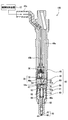
燃料噴射装置の縦断面図であり、
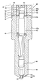
燃料噴射装置の制御ボデーを拡大した図であり、
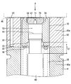
スペーサとその近傍を拡大した図であり、
図4の矢印Vの方向に見たスペーサ等の平面図であり、
図3の変形例を示す図である。
図1に示す燃料供給システム10には、本開示の一実施形態による燃料噴射装置100が用いられている。燃料供給システム10は、内燃機関であるディーゼル機関20の燃焼室22に、燃料噴射装置100によって燃料を供給する。燃料供給システム10は、フィードポンプ12、高圧燃料ポンプ13、コモンレール14、機関制御装置17、及び燃料噴射装置100等から構成されている。
フィードポンプ12は、燃料タンク11内に収容された電動式のポンプである。フィードポンプ12は、燃料タンク11内に貯留されている軽油等の燃料に、燃料の蒸気圧よりも高いフィード圧を与える。フィードポンプ12は、燃料配管12aによって高圧燃料ポンプ13と接続されている。フィードポンプ12は、所定のフィード圧を与えた液相状態の燃料を高圧燃料ポンプ13に供給する。
高圧燃料ポンプ13は、ディーゼル機関20に取り付けられており、ディーゼル機関の出力軸によって駆動される。高圧燃料ポンプ13は、燃料配管13aによってコモンレール14と接続されている。高圧燃料ポンプ13は、フィードポンプ12によって供給された燃料をさらに昇圧し、コモンレール14に供給する高圧燃料をつくり出す。高圧燃料ポンプ13は、機関制御装置17と電気的に接続された電磁弁を有している。電磁弁の開閉が機関制御装置17によって制御されることにより、高圧燃料ポンプ13からコモンレール14に供給される燃料の圧力は、所定の圧力に調節される。
コモンレール14は、クロムモリブデン鋼等の金属材料で構成される管状の部材である。コモンレール14には、ディーゼル機関の気筒数に応じた複数の分岐部14aが形成されている。各分岐部14aは、燃料配管14dによって、複数の燃料噴射装置100のうちのいずれかに接続されている。コモンレール14は、高圧燃料ポンプ13から供給される高圧燃料を一時的に蓄え、圧力を保持したまま複数の燃料噴射装置100に分配する。
コモンレール14には、コモンレールセンサ14b及び圧力レギュレータ14cが設けられている。コモンレールセンサ14bは、機関制御装置17に電気的に接続されており、燃料の圧力及び温度を検出して機関制御装置17に出力する。圧力レギュレータ14cは、コモンレール14の端部に取り付けられている。圧力レギュレータ14cは、コモンレール14内の燃料の圧力を一定に保持すると共に、余剰分の燃料を減圧して低圧側に排出する。圧力レギュレータ14cから排出された余剰燃料は、コモンレール14及び燃料タンク11間を接続している燃料配管14eを通じて、燃料タンク11に戻される。
機関制御装置17は、演算回路としてのプロセッサ、RAM、及び書き換え可能な不揮発性の記憶媒体を含むマイクロコンピュータ等によって構成されている。機関制御装置17は、コモンレールセンサ14bに加えて、ディーゼル機関20の回転速度を検出する回転速度センサ等、種々のセンサと電気的に接続されている。機関制御装置17は、これらの各センサからの情報に基づいて、高圧燃料ポンプ13の電磁弁及び各燃料噴射装置100の弁機構を制御するための制御信号を、高圧燃料ポンプ13及び各燃料噴射装置100に出力する。
燃料噴射装置100は、燃焼室22に直接的に燃料を噴射する。燃料噴射装置100は、ディーゼル機関20の燃焼室22を形成するヘッド部材21の挿入孔に挿入された状態で、ヘッド部材21に取り付けられている。燃料噴射装置100は、燃料配管14dから供給された高圧燃料を、噴孔44から燃焼室22に噴射する。燃料噴射装置100の噴射圧力は、160~250メガパスカル(MPa)程度である。燃料噴射装置100は、噴孔44からの高圧燃料の噴射を制御する弁機構を備えている。弁機構は、機関制御装置17からの制御信号に基づいて作動する圧力制御弁35(図2等参照)と、噴孔44を開閉する主弁部50と、を含んでいる。燃料噴射装置100は、噴孔44を開閉するために、燃料配管14dから供給される高圧燃料の一部を使用する。こうした燃料は、低圧側である燃料配管14fに排出され、燃料配管14eを通じて燃料タンク11に戻される。
燃料噴射装置100は、図2に示すように、駆動部30、制御ボデー40、ノズルニードル60、及びフローティングプレート70を備えている。
駆動部30は、制御ボデー40内に収容されている。駆動部30は、制御弁フェース部材33と接続されている。制御弁フェース部材33は、制御シート部46aと共に圧力制御弁35を形成している。駆動部30には、パルス状の制御信号が機関制御装置17から供給される。駆動部30は、制御信号に基づいて制御弁フェース部材33を変位させることにより、圧力制御弁35を開閉する。機関制御装置17からの電力供給が無い場合、駆動部30は、制御弁フェース部材33を制御シート部46aに着座させる。これにより、圧力制御弁35は閉弁状態となる。機関制御装置17からの電力供給が有る場合、駆動部30は、制御弁フェース部材33を制御シート部46aから離座させる。これにより、圧力制御弁35は開弁状態となる。
制御ボデー40は、図2及び図3に示すように、噴孔44、流入通路52、流出通路54、供給通路55、及び圧力制御室53を形成している。噴孔44は、燃焼室22(図1参照)へ挿入される制御ボデー40の挿入方向の先端部に形成されている。先端部は、円錐状又は半球状に形成されている。噴孔44は、制御ボデー40の内側から外側に向けて放射状に複数設けられている。噴孔44を通じて、高圧燃料が燃焼室22内に噴射される。噴孔44を通過することにより、高圧燃料は、微粒化及び拡散して空気と混合し易い状態となる。
流入通路52の第1通路端は、縦孔48aと接続されている。流入通路52の第2通路端は、圧力制御室53に繋がっている。流入通路52は、燃料配管14d(図1参照)及び縦孔48aを通じて供給される高圧燃料を、圧力制御室53に流入させる。流出通路54の第1通路端は、圧力制御弁35に繋がっている。流出通路54の第2通路端は、圧力制御室53に繋がっている。流出通路54は、圧力制御弁35の開弁により、圧力制御室53内の燃料を燃料配管14f(図1参照)に流出させる。
供給通路55は、制御ボデー40の内部において流入通路52から分岐している。供給通路55は、制御ボデー40を形成する複数の部材に跨って、円筒穴状に形成されている。供給通路55は、燃料配管14d(図1参照)と噴孔44とを連通させている。供給通路55は、燃料配管14dを通じて供給される高圧燃料を、噴孔44に流通させる。
圧力制御室53は、制御ボデー40の内部においてノズルニードル60を挟んで噴孔44の反対側に位置している。圧力制御室53は、流入通路52からの高圧燃料の流入と、流出通路54を通じた燃料の流出とによって圧力を変動させる。こうした燃料の圧力を用いて、圧力制御室53は、ノズルニードル60の移動を制御する。
制御ボデー40は、ノズルボデー41、シリンダ56、オリフィスプレート46、ホルダ48、リテーニングナット49、及びスペーサ80等によって構成されている。ノズルボデー41、スペーサ80、オリフィスプレート46、及びホルダ48は、ヘッド部材21(図1参照)への挿入方向の先端部側から、この順序で並んでいる。
ノズルボデー41は、クロムモリブデン鋼等の金属材料よって形成された有底円筒状の部材である。ノズルボデー41には、噴孔44と、供給通路55の一部とが形成されている。ノズルボデー41は、ノズルニードル収容室43及びシート部45を有している。
ノズルニードル収容室43は、周壁部43aによって外周側を区画された円筒穴である。ノズルニードル収容室43は、ノズルニードル60を収容している。ノズルニードル収容室43は、ノズルボデー41の軸方向に沿って形成されている。ノズルニードル収容室43は、ノズルボデー41のオリフィスプレート46側の端面に開口している。ノズルニードル収容室43は、供給通路55を形成している。
シート部45は、供給通路55に臨むノズルボデー41の内周壁によって円錐状に形成されている。シート部45は、先端部の内側に位置しており、ノズルニードル60の先端と接触する。シート部45は、ノズルニードル収容室43の開口から挿入される長尺形状の切削工具によって機械加工される。シート部45の形成に用いられる切削工具には、先端に加工反力を受けても実質的に変形しないような高い剛性が必要とされる。
シリンダ56は、図2~図4に示すように、金属材料によって円筒状に形成されている。シリンダ56は、オリフィスプレート46及びノズルニードル60と共に圧力制御室53を区画している。シリンダ56は、スペーサ80の内周側に、スペーサ80と同軸となるよう配置されている。シリンダ56は、軸方向の一方の端面をオリフィスプレート46に接触させている。シリンダ56は、ノズルニードル60を軸方向に沿って摺動させる。シリンダ56には、ニードルストッパ57及びプレートストッパ58が設けられている。ニードルストッパ57は、フローティングプレート70に近接する方向であって、シート部45から離れる方向へのノズルニードル60の変位を規制する。プレートストッパ58は、ノズルニードル60に近接する方向であって、オリフィスプレート46から離れる方向へのフローティングプレート70の変位を規制する。
オリフィスプレート46は、図2に示すように、クロムモリブデン鋼等の金属材料よって円盤状に形成されている。オリフィスプレート46には、流入通路52及び流出通路54と、供給通路55の一部とが形成されている。オリフィスプレート46は、制御シート部46a及び当接壁面部47を有している。
制御シート部46aは、ホルダ48側を向くオリフィスプレート46の頂面に形成されている。制御シート部46aは、制御弁フェース部材33と共に圧力制御弁35を形成している。圧力制御弁35は、流出通路54と燃料配管14f(図1参照)との間の連通及び遮断を切り換える。
当接壁面部47は、ノズルニードル60側を向くオリフィスプレート46の底面に形成されている。当接壁面部47は、オリフィスプレート46の底面のうちで、シリンダ56によって囲まれた円形状の領域である。当接壁面部47は、圧力制御室53を区画している。当接壁面部47には、圧力制御室53に高圧燃料を流入させる流入通路52の開口52aと、圧力制御室53から燃料を流出させる流出通路54の開口54aとが形成されている。当接壁面部47には、圧力制御室53内を軸方向に往復変位するフローティングプレート70が当接する。
ホルダ48は、クロムモリブデン鋼等の金属材料よりなる筒状の部材である。ホルダ48には、軸方向に沿う縦孔48a,48b、及びソケット部48cが形成されている。縦孔48aは、燃料配管14d(図1参照)と流入通路52及び供給通路55とを繋いでいる。縦孔48bは、駆動部30を収容している。ソケット部48cは、縦孔48bの開口を塞ぐように形成されている。ソケット部48cには、機関制御装置17と接続されたプラグ部が嵌合される。ソケット部48cに接続されたプラグ部を通じて、機関制御装置17から駆動部30にパルス状の制御信号が供給される。
リテーニングナット49は、金属材料よりなる二段円筒状の部材である。リテーニングナット49は、ノズルボデー41の一部、スペーサ80、オリフィスプレート46(以下、「要素41~46」と記載)を収容しつつ、ホルダ48に螺合されている。リテーニングナット49は、段差部49aを有している。段差部49aは、径方向の段差を形成している。段差部49aは、リテーニングナット49のホルダ48への取り付けにより、要素41~46をホルダ48へ向けて押し付ける。リテーニングナット49は、要素41~46を、ホルダ48と共に挟持している。
スペーサ80は、図3~図5に示すように、クロムを含有する高炭素鋼等の金属材料によって円筒状に形成されている。スペーサ80は、ノズルボデー41及びオリフィスプレート46との間に、これらと同軸となるように配置されている。スペーサ80は、円筒状の外周壁80aを有している。外周壁80aには、回収通路81と二つの環状溝82,83が形成されている。
外周壁80aは、シリンダ56と同軸となるよう配置され、シリンダ56の外周側を囲んでいる。外周壁80aとノズルボデー41との間には、供給通路55が形成されている。外周壁80aの内径は、ノズルボデー41の周壁部43aの内径と実質的に同一である。外周壁80aの壁厚は、周壁部43aの壁厚と実質的に同一である。
回収通路81は、外周壁80aに形成されることにより、供給通路55の外周側に位置している。回収通路81は、スペーサ80の軸方向に沿って延伸する円筒穴である。回収通路81は、各環状溝82,83の各底面に両端を開口させている。回収通路81は、スペーサ80とオリフィスプレート46との間に供給通路55から漏れ出るリーク燃料を回収する燃料通路である。
環状溝82,83は、外周壁80aの軸方向の両端面に形成されている。環状溝82,83は、各端面を凹状に窪ませた凹溝である。環状溝82,83は、外周壁80aと同心の円環状に形成されている。各環状溝82,83の形状は、互いに同一である。ノズルボデー41に臨む第1環状溝82には、スペーサ80とノズルボデー41との間に供給通路55から漏れ出たリーク燃料が流入する。リーク燃料は、回収通路81を通じて、オリフィスプレート46に臨む第2環状溝83へ移動する。そして、リーク燃料は、オリフィスプレート46に形成された燃料通路を通じて、燃料配管14f(図1参照)に排出される。
以上のスペーサ80は、軸方向において上下に対称な形状に形成されている。詳記すると、スペーサ80は、軸方向の中央に位置する仮想の横断面に対して面対称な形状である。こうした形状により、スペーサ80は、頂面と底面とを入れ替えた姿勢にて配置することが可能である。加えて、各環状溝82,83が円環状であるため、周方向における回収通路81の位置は、規定されなくてもよい。故にスペーサ80は、周方向の向きを規定されることなく、ノズルボデー41及びオリフィスプレート46との間に配置されている。
ノズルニードル60は、図3及び図4に示すように、高速度工具鋼等の金属材料によって全体として円柱状に形成されている。ノズルニードル60は、ノズルボデー41の内部において、ノズルボデー41の軸方向に沿って往復移動する。ノズルニードル60は、金属製の線材を螺旋状に巻設したリターンスプリング66により、シート部45に向けて付勢されている。ノズルニードル60は、フェース部65及び弁受圧面61を有している。
フェース部65は、ノズルニードル60の両端部のうちで、シート部45と対向する一方の端部に形成されている。フェース部65は、先端に向かうに従って外径の減少する円錐状に形成されている。フェース部65は、ノズルニードル60の変位により、シート部45に離着座する。フェース部65は、噴孔44を開閉する主弁部50をシート部45と共に形成している。
弁受圧面61は、ノズルニードル60の軸方向の両端部のうち、圧力制御室53側の端部によって形成されている。弁受圧面61は、オリフィスプレート46及びシリンダ56と共に圧力制御室53を区画している。弁受圧面61に受ける燃料圧力の変動により、ノズルニードル60は、フェース部65をシート部45へ離着座させる。
フローティングプレート70は、図2、図4、及び図5に示すように、金属材料によって円盤状に形成されている。フローティングプレート70は、圧力制御室53内に配置されている。フローティングプレート70は、ノズルボデー41の軸方向に沿って往復変位する。フローティングプレート70は、流出通路54から流出しようとする圧力制御室53内の燃料の圧力により、当接壁面部47に押し付けられる。こうして流出通路54に向けて吸引されたフローティングプレート70は、流入通路52の開口52aを閉じる。その結果、流入通路52から圧力制御室53への高圧燃料の流入が妨げられる。
フローティングプレート70には、連通孔71が形成されている。連通孔71は、フローティングプレート70の径方向の中心に設けられている。連通孔71は、軸方向に沿ってフローティングプレート70を貫通している。フローティングプレート70は、流入通路52の開口52aを閉じた状態下においても、所定の流量の燃料を、連通孔71を通じて圧力制御室53から流出通路54へと流出させることができる。
次に、燃料噴射装置100が噴孔44を開閉させる作動を説明する。まず、圧力制御弁35の開弁により、流出通路54が、燃料配管14f(図1参照)と連通状態となる。すると、圧力制御室53から流出する燃料によって流出通路54に吸引されたフローティングプレート70が、流入通路52の開口52aを閉じる。これにより、圧力制御室53への高圧燃料の導入が妨げられる一方で、連通孔71を通じた燃料の流出は継続される。その結果、圧力制御室53内の燃料圧力の下降がすみやかに生じ、ノズルニードル60は、圧力制御室53側に素早く移動して、噴孔44を開状態とする。
ノズルニードル60は、ニードルストッパ57に接触することなく、シート部45から離れる方向へ移動する。そして、圧力制御弁35の閉弁により、流出通路54と燃料配管14f(図1参照)とが遮断状態とされると、フローティングプレート70は、流入通路52の燃料に押されて、当接壁面部47から離れる方向へ移動する。以上により、圧力制御室53の圧力が回復することで、ノズルニードル60は、シート部45側に素早く移動して、噴孔44を閉状態とする。
以上の作動において、ノズルニードル60は、シート部45から離れる方向への最大ストロークST(図4参照)が予め設定されている。何らかの異常によって最大ストロークST以上移動した場合、ノズルニードル60は、ニードルストッパ57との接触によって移動を規制される。即ち、ノズルニードル60は、通常の作動では、ニードルストッパ57と接触することなく、所定の最大ストロークST以下の移動によって噴孔44からの燃料の噴射を開始させる。本実施形態では、こうした最大ストロークSTを、シート部45の加工精度を悪化させることなく、延長させることが可能である。
詳しく説明すると、本実施形態では、圧力制御室53の外周の供給通路55がスペーサ80によって形成されている。故に、ノズルニードル60の最大ストロークSTの延長に伴って圧力制御室53、ひいてはシリンダ56が軸方向に拡大されても、スペーサ80を軸方向へ拡大すればよい。そのため、ノズルボデー41の体格は維持され得る。
仮に、ノズルボデー41の体格が軸方向に延長されてしまうと、ノズルニードル収容室43の開口からシート部45までの距離が離れることとなる。その結果、シート部45の加工に用には、さらに長い形状の切削工具が必要となる。切削工具の剛性は、長くなるほど当然に低下する。故に、シート部45の加工精度の維持が著しく困難になってしまうのである。
対して、上述の如く、ノズルボデー41の体格が維持可能な本実施形態では、可能が困難になる事態は、回避され得る。したがって、ノズルボデー41にシート部45を形成する際の加工精度の悪化を抑えつつ、ノズルニードル60のストローク量を確保することが可能となる。
加えて本実施形態では、燃料の圧力が異常に上昇した場合でも、燃料噴射装置100外部への燃料漏れは、防がれ得る。詳しく説明すると、燃料噴射装置100には、供給通路55の外周側に回収通路81が形成されている。故に、仮に想定外の異常な高圧燃料の負荷によって供給通路55からの漏出が生じたとしても、こうしたリーク燃料は、回収通路81によって確実に回収され得る。したがって、スペーサ80を追加したとしても、外部への燃料漏れは、確実に防がれる。
また本実施形態のようなスペーサ80には、外周壁80aの両端面の平行度に、ばらつきが不可避的に生じる。こうした平行度のばらつきは、外周壁80aが軸方向に長くなるほど、ノズルボデー41の中心軸を、燃料噴射装置100の中心軸から大きくずれさせてしまう。そのため本実施形態のように、外周壁80aの軸方向の長さは、外周壁80aの外径よりも短く抑えられることが望ましい。こうしたスペーサ80の形状によれば、頂面と底面との間の平行度について管理幅を広く確保したうえで、ノズルニードル60の中心軸のずれを許容範囲内に抑えることが可能となる。
さらに本実施形態のように、追加されるスペーサ80の外周壁80aの内径及び壁厚は、ノズルボデー41の周壁部43aの内径及び壁厚と揃えられることが望ましい。こうした構成であれば、外周壁80aは、供給通路55を流通する燃料の圧力に対して最適な強度を獲得し得る。また、燃料噴射装置100の外径の拡大も防がれ得る。
加えて本実施形態では、噴孔44が開状態にある期間に亘って、ノズルニードル60の移動は継続される。故に、ノズルニードル60の最大ストロークSTを長く確保する必要が生じる。そのため、スペーサ80によってシート部45の加工精度の維持と最大ストロークSTの延長とを両立させる構成は、通常作動時のノズルニードル60の移動がニードルストッパ57によって規制されない燃料噴射装置100に、特に好適なのである。
そして、以上のようにノズルニードル60の移動が規制されない構成では、圧力制御弁35が閉じられるまで、フローティングプレート70は、流入通路52の開口52aを塞ぎ続ける。故に、圧力制御弁35の開弁時において、流入通路52から圧力制御室53を通じて流出通路54へと流通する燃料が低減される。こうして、噴孔44から噴射されることなく、燃料タンク11に戻されるリーク燃料の低減が可能となる。
尚、本実施形態において、ディーゼル機関20が内燃機関に相当し、ノズルボデー41が弁本体に相当し、オリフィスプレート46がオリフィス部材に相当する。また、開口52aが流入口に相当し、供給通路55が燃料通路に相当し、シリンダ56が区画部材に相当する。さらに、ニードルストッパ57が規制部に相当し、ノズルニードル60が弁部材に相当し、フローティングプレート70が押圧部材に相当する。そして、スペーサ80が外周部材に相当する。
(他の実施形態)
以上、本開示による一実施形態について説明したが、本開示は、上記実施形態に限定して解釈されるものではなく、本開示の要旨を逸脱しない範囲内において種々の実施形態及び組み合わせに適用することができる。
以上、本開示による一実施形態について説明したが、本開示は、上記実施形態に限定して解釈されるものではなく、本開示の要旨を逸脱しない範囲内において種々の実施形態及び組み合わせに適用することができる。
上記実施形態において、スペーサ80の軸方向長さは、外径よりも短く、シリンダ56と同程度とされていた。しかし、スペーサの形状は、適宜変更可能である。例えば図6に示す変形例の制御ボデー140のように、スペーサ180の軸方向の長さは、外径よりも長くすることが可能である。こうしたすスペーサ180の採用によれば、ノズルボデー141の軸方向の長さは、いっそう短縮され得る。その結果、ノズルニードル収容室143の開口からシート部145までの距離が縮まるため、シート部145の加工精度は、さらに確保され易くなる。尚、この変形例においては、ノズルボデー141が弁本体に相当し、スペーサ180が外周部材に相当する。
さらに、スペーサの内径及び壁厚は、ノズルボデーと異なっていてもよい。また、回収通路81及び環状溝82,83に相当する構成をスペーサから省略することが可能である。具体的には、環状溝83のような円環状の環状溝が、スペーサと接するオリフィスプレートの端面に形成されていてもよい。同様に、環状溝82のような円環状の環状溝が、スペーサと接するノズルボデーの端面に形成されていてもよい。
上記実施形態のような構成であれば、圧力制御室53の容積が互いに異なる燃料噴射装置を作り分けることが容易となる。詳記すると、燃料噴射装置100の製造時において、ノズルニードル60の移動方向に沿った軸方向長さが互いに異なる複数種類の部材の中から、一種類がシリンダ56として選択される。このように、圧力制御室53を区画するシリンダ56を選択式とすることにより、圧力制御室53の容積は、容易に変更可能となる。さらに、スペーサ80も、軸方向長さが互いに異なる複数種類の中から、シリンダ56に対応した一種類が選択される。選択されるスペーサ80の軸方向長さは、シリンダ56の軸方向長さに対応して、適宜変更可能である。以上の構成であれば、圧力制御室53及びシリンダ56が軸方向に拡大されたとしても、ノズルニードル60の軸方向への拡大は、防がれ得る。故に、シート部45の加工精度を悪化させることなく、複数種類のストローク量をそれぞれ確保することが可能となる。加えて、ノズルボデー41の種別の増加を抑えることも可能となる。
また、上記実施形態では、シート部を形成するノズルボデーには、単純な円筒部材であるスペーサよりも、加工性に優れた材料が採用されていた。しかし、ノズルボデーと同一の材料でスペーサを形成することが可能である。
上記実施形態にて示したように、ストロークの拡大とシート部の加工精度の維持という背反を解決する効果は、通常時にノズルニードルがニードルストッパに当接しない形態に適用されて、リーク燃料の低減と噴射量の増加とを両立させるために顕著に有効である。しかし、通常作動時にてノズルニードルがニードルストッパに当接する形態の燃料噴射装置にも、本開示は適用可能である。さらに、圧力制御室内にフローティングプレートを設けていない形態の燃料噴射装置にも、本開示は適用可能である。尚、上記実施形態のような異常なストロークを止めるニードルストッパは、シリンダから省略されていてもよい。
以上、ディーゼル機関に用いられる燃料噴射装置に、本開示を適用した例を説明した。しかし、本開示は、ディーゼル機関に限らず、オットーサイクル機関等の内燃機関に用いられる燃料噴射装置に適用されてもよい。加えて、燃料噴射装置によって噴射される燃料は、軽油に限らず、ジメチルエーテル、液化石油ガス、ガソリン等であってもよい。
本開示は、実施例に準拠して記述されたが、本開示は当該実施例や構造に限定されるものではないと理解される。本開示は、様々な変形例や均等範囲内の変形をも包含する。加えて、様々な組み合わせや形態、さらには、それらに一要素のみ、それ以上、あるいはそれ以下、を含む他の組み合わせや形態をも、本開示の範疇や思想範囲に入るものである。
Claims (9)
- 内燃機関(20)の燃焼室(22)に供給される燃料を噴孔(44)から噴射する燃料噴射装置であって、
前記噴孔に燃料を流通させる燃料通路(55)及び前記燃料通路に臨むシート部(45,145)が形成される弁本体(41,141)と、
前記弁本体の内部において前記弁本体の軸方向に沿って移動し、前記シート部に対して離着座することで前記噴孔を開閉する弁部材(60)と、
前記弁部材を挟んで前記噴孔の反対側に位置し、導入される燃料の圧力によって前記弁部材の移動を制御する圧力制御室(53)、を区画する区画部材(56)と、
前記区画部材の外周側を囲み、前記燃料通路を前記弁本体と共に形成する外周部材(80,180)と、を備える燃料噴射装置。 - 前記外周部材には、前記燃料通路の外周側に位置し、前記外周部材と前記弁本体との間に前記燃料通路から漏れ出る燃料を回収する回収通路(81)、が形成される請求項1に記載の燃料噴射装置。
- 前記外周部材は、前記燃料通路の外周側を囲む円筒状の外周壁(80a)を有し、
前記外周壁の軸方向の長さは、前記外周壁の外径よりも短い請求項1又は2に記載の燃料噴射装置。 - 前記弁本体は、前記弁部材を収容する円筒穴状の前記燃料通路を形成し、
前記外周壁の内径は、前記弁本体の内径と実質的に同一である請求項3に記載の燃料噴射装置。 - 前記外周壁の壁厚は、前記弁本体において前記燃料通路を囲む周壁部(43a)の壁厚と実質的に同一である請求項3又は4に記載の燃料噴射装置。
- 前記弁部材は、前記シート部から離れる方向への予め設定された最大ストローク以下の移動により、前記噴孔からの燃料の噴射を開始させ、
前記区画部材は、前記最大ストローク(ST)を超える前記弁部材の移動を規制する規制部(57)、を有する請求項1~5のいずれか一項に記載の燃料噴射装置。 - 前記外周部材を挟んで前記弁本体の反対側に位置し、前記圧力制御室に燃料を流入させる流入口(52a)を形成するオリフィス部材(46)と、
前記圧力制御室内に配置され、前記圧力制御室内の燃料の圧力によって前記オリフィス部材に押し付けられることで、前記流入口から前記圧力制御室への燃料の流入を妨げる押圧部材(70)と、をさらに備える請求項1~6のいずれか一項に記載の燃料噴射装置。 - 前記区画部材は、前記弁部材の移動方向に沿った長さが互いに異なる複数種類の中から選択された一つである請求項1~7のいずれか一項に記載の燃料噴射装置。
- 前記外周部材は、前記移動方向に沿った長さが互いに異なる複数種類の中から選択された一つであり、前記区画部材の長さに対応している請求項8に記載の燃料噴射装置。
Priority Applications (3)
| Application Number | Priority Date | Filing Date | Title |
|---|---|---|---|
| US15/523,974 US10151285B2 (en) | 2015-03-09 | 2016-02-16 | Fuel injection device |
| CN201680003519.2A CN107110083B (zh) | 2015-03-09 | 2016-02-16 | 燃料喷射装置 |
| DE112016001145.8T DE112016001145T5 (de) | 2015-03-09 | 2016-02-16 | Kraftstoffeinspritzvorrichtung |
Applications Claiming Priority (2)
| Application Number | Priority Date | Filing Date | Title |
|---|---|---|---|
| JP2015046184A JP6384366B2 (ja) | 2015-03-09 | 2015-03-09 | 燃料噴射装置 |
| JP2015-046184 | 2015-03-09 |
Publications (1)
| Publication Number | Publication Date |
|---|---|
| WO2016143264A1 true WO2016143264A1 (ja) | 2016-09-15 |
Family
ID=56880344
Family Applications (1)
| Application Number | Title | Priority Date | Filing Date |
|---|---|---|---|
| PCT/JP2016/000797 Ceased WO2016143264A1 (ja) | 2015-03-09 | 2016-02-16 | 燃料噴射装置 |
Country Status (5)
| Country | Link |
|---|---|
| US (1) | US10151285B2 (ja) |
| JP (1) | JP6384366B2 (ja) |
| CN (1) | CN107110083B (ja) |
| DE (1) | DE112016001145T5 (ja) |
| WO (1) | WO2016143264A1 (ja) |
Cited By (1)
| Publication number | Priority date | Publication date | Assignee | Title |
|---|---|---|---|---|
| CN108131230A (zh) * | 2017-12-26 | 2018-06-08 | 南岳电控(衡阳)工业技术股份有限公司 | 一种柴油机高压共轨重型机械喷油器 |
Families Citing this family (2)
| Publication number | Priority date | Publication date | Assignee | Title |
|---|---|---|---|---|
| DE102019104294A1 (de) * | 2018-03-15 | 2019-09-19 | Denso Corporation | Korrosionsbeständige Vorrichtung |
| JP7024567B2 (ja) * | 2018-04-06 | 2022-02-24 | 株式会社デンソー | 燃料噴射弁 |
Citations (5)
| Publication number | Priority date | Publication date | Assignee | Title |
|---|---|---|---|---|
| JP2002322960A (ja) * | 2001-04-27 | 2002-11-08 | Nippon Soken Inc | 燃料噴射弁 |
| JP2005526211A (ja) * | 2002-05-18 | 2005-09-02 | ローベルト ボツシユ ゲゼルシヤフト ミツト ベシユレンクテル ハフツング | 内燃機関用の燃料噴射弁 |
| JP2005531712A (ja) * | 2002-06-29 | 2005-10-20 | ローベルト ボツシユ ゲゼルシヤフト ミツト ベシユレンクテル ハフツング | 噴射終了時の迅速な減圧を伴う増圧式の燃料インジェクタ |
| JP2009515094A (ja) * | 2005-11-09 | 2009-04-09 | キャタピラー インコーポレイテッド | 可変圧力噴射用の多源燃料システム |
| JP2013510268A (ja) * | 2009-11-10 | 2013-03-21 | ローベルト ボッシュ ゲゼルシャフト ミット ベシュレンクテル ハフツング | 燃料噴射弁を製造する方法、及び、燃料噴射弁 |
Family Cites Families (10)
| Publication number | Priority date | Publication date | Assignee | Title |
|---|---|---|---|---|
| JPH0765550B2 (ja) * | 1988-10-21 | 1995-07-19 | いすゞ自動車株式会社 | 蓄圧式燃料噴射装置 |
| US5779149A (en) * | 1996-07-02 | 1998-07-14 | Siemens Automotive Corporation | Piezoelectric controlled common rail injector with hydraulic amplification of piezoelectric stroke |
| JP2002031016A (ja) * | 2000-07-21 | 2002-01-31 | Toyota Industries Corp | 燃料噴射器 |
| US7963464B2 (en) * | 2008-01-23 | 2011-06-21 | Caterpillar Inc. | Fuel injector and method of assembly therefor |
| DE102008002527A1 (de) * | 2008-06-19 | 2009-12-24 | Robert Bosch Gmbh | Kraftstoff-Injektor |
| CN101338716B (zh) * | 2008-09-02 | 2013-07-03 | 兰州泰瑞液压设备有限公司 | 新式高压共轨电控喷油器 |
| JP5625837B2 (ja) | 2010-03-31 | 2014-11-19 | 株式会社デンソー | 燃料噴射装置 |
| JP5375762B2 (ja) * | 2010-07-14 | 2013-12-25 | 株式会社デンソー | 燃料噴射装置 |
| JP5304861B2 (ja) | 2010-12-17 | 2013-10-02 | 株式会社デンソー | 燃料噴射装置 |
| JP6708366B2 (ja) | 2015-03-09 | 2020-06-10 | 株式会社デンソー | 燃料噴射装置及び燃料噴射装置の製造方法 |
-
2015
- 2015-03-09 JP JP2015046184A patent/JP6384366B2/ja active Active
-
2016
- 2016-02-16 WO PCT/JP2016/000797 patent/WO2016143264A1/ja not_active Ceased
- 2016-02-16 US US15/523,974 patent/US10151285B2/en active Active
- 2016-02-16 DE DE112016001145.8T patent/DE112016001145T5/de not_active Ceased
- 2016-02-16 CN CN201680003519.2A patent/CN107110083B/zh active Active
Patent Citations (5)
| Publication number | Priority date | Publication date | Assignee | Title |
|---|---|---|---|---|
| JP2002322960A (ja) * | 2001-04-27 | 2002-11-08 | Nippon Soken Inc | 燃料噴射弁 |
| JP2005526211A (ja) * | 2002-05-18 | 2005-09-02 | ローベルト ボツシユ ゲゼルシヤフト ミツト ベシユレンクテル ハフツング | 内燃機関用の燃料噴射弁 |
| JP2005531712A (ja) * | 2002-06-29 | 2005-10-20 | ローベルト ボツシユ ゲゼルシヤフト ミツト ベシユレンクテル ハフツング | 噴射終了時の迅速な減圧を伴う増圧式の燃料インジェクタ |
| JP2009515094A (ja) * | 2005-11-09 | 2009-04-09 | キャタピラー インコーポレイテッド | 可変圧力噴射用の多源燃料システム |
| JP2013510268A (ja) * | 2009-11-10 | 2013-03-21 | ローベルト ボッシュ ゲゼルシャフト ミット ベシュレンクテル ハフツング | 燃料噴射弁を製造する方法、及び、燃料噴射弁 |
Cited By (2)
| Publication number | Priority date | Publication date | Assignee | Title |
|---|---|---|---|---|
| CN108131230A (zh) * | 2017-12-26 | 2018-06-08 | 南岳电控(衡阳)工业技术股份有限公司 | 一种柴油机高压共轨重型机械喷油器 |
| CN108131230B (zh) * | 2017-12-26 | 2024-03-08 | 南岳电控(衡阳)工业技术股份有限公司 | 一种柴油机高压共轨重型机械喷油器 |
Also Published As
| Publication number | Publication date |
|---|---|
| DE112016001145T5 (de) | 2017-11-23 |
| US20170356409A1 (en) | 2017-12-14 |
| JP6384366B2 (ja) | 2018-09-05 |
| US10151285B2 (en) | 2018-12-11 |
| CN107110083B (zh) | 2019-05-07 |
| CN107110083A (zh) | 2017-08-29 |
| JP2016166561A (ja) | 2016-09-15 |
Similar Documents
| Publication | Publication Date | Title |
|---|---|---|
| US6729600B2 (en) | Valve for regulating fluids | |
| US7703708B2 (en) | Fuel injection valve | |
| US9127629B2 (en) | Fuel injection device | |
| US8544767B2 (en) | Fuel injection device | |
| EP3252301B1 (en) | Fuel injector for a dual fuel engine | |
| KR101917389B1 (ko) | 수동 용량 제한 밸브 | |
| CN102042143A (zh) | 减压阀 | |
| JP5327117B2 (ja) | 燃料噴射装置 | |
| JP2007192159A (ja) | コモンレール | |
| JP5732834B2 (ja) | 燃料噴射装置 | |
| JP6384366B2 (ja) | 燃料噴射装置 | |
| CN105658945A (zh) | 尤其是控制活塞/控制孔布置结构的活塞/流体管路布置结构 | |
| JP6708366B2 (ja) | 燃料噴射装置及び燃料噴射装置の製造方法 | |
| US20140352664A1 (en) | Flow limiting system | |
| JP5936764B2 (ja) | 流量制限器を備えたモジュール式のコモンレール燃料噴射装置のインジェクタ | |
| JP6939390B2 (ja) | 燃料噴射弁 | |
| JP6413847B2 (ja) | 燃料噴射装置 | |
| JP2008008281A (ja) | 燃料噴射弁 | |
| EP3023628B1 (en) | A fuel flow limiting valve for large internal combustion engines | |
| US9695790B2 (en) | Hydraulic system | |
| JP5434702B2 (ja) | 燃料噴射装置 | |
| JP5494453B2 (ja) | 燃料噴射装置 | |
| JP5353785B2 (ja) | 燃料噴射装置 | |
| JP2020143586A (ja) | 圧力調整装置 | |
| JP2016084774A (ja) | 燃料噴射弁 |
Legal Events
| Date | Code | Title | Description |
|---|---|---|---|
| 121 | Ep: the epo has been informed by wipo that ep was designated in this application |
Ref document number: 16761243 Country of ref document: EP Kind code of ref document: A1 |
|
| WWE | Wipo information: entry into national phase |
Ref document number: 15523974 Country of ref document: US |
|
| WWE | Wipo information: entry into national phase |
Ref document number: 112016001145 Country of ref document: DE |
|
| 122 | Ep: pct application non-entry in european phase |
Ref document number: 16761243 Country of ref document: EP Kind code of ref document: A1 |