WO2016143276A1 - Dispositif acoustique et procédé de correction - Google Patents
Dispositif acoustique et procédé de correction Download PDFInfo
- Publication number
- WO2016143276A1 WO2016143276A1 PCT/JP2016/000917 JP2016000917W WO2016143276A1 WO 2016143276 A1 WO2016143276 A1 WO 2016143276A1 JP 2016000917 W JP2016000917 W JP 2016000917W WO 2016143276 A1 WO2016143276 A1 WO 2016143276A1
- Authority
- WO
- WIPO (PCT)
- Prior art keywords
- sound
- unit
- sound output
- acoustic device
- test
- Prior art date
- Legal status (The legal status is an assumption and is not a legal conclusion. Google has not performed a legal analysis and makes no representation as to the accuracy of the status listed.)
- Ceased
Links
Images





Classifications
-
- H—ELECTRICITY
- H04—ELECTRIC COMMUNICATION TECHNIQUE
- H04S—STEREOPHONIC SYSTEMS
- H04S7/00—Indicating arrangements; Control arrangements, e.g. balance control
- H04S7/30—Control circuits for electronic adaptation of the sound field
- H04S7/301—Automatic calibration of stereophonic sound system, e.g. with test microphone
-
- G—PHYSICS
- G01—MEASURING; TESTING
- G01H—MEASUREMENT OF MECHANICAL VIBRATIONS OR ULTRASONIC, SONIC OR INFRASONIC WAVES
- G01H17/00—Measuring mechanical vibrations or ultrasonic, sonic or infrasonic waves, not provided for in the other groups of this subclass
-
- G—PHYSICS
- G10—MUSICAL INSTRUMENTS; ACOUSTICS
- G10K—SOUND-PRODUCING DEVICES; METHODS OR DEVICES FOR PROTECTING AGAINST, OR FOR DAMPING, NOISE OR OTHER ACOUSTIC WAVES IN GENERAL; ACOUSTICS NOT OTHERWISE PROVIDED FOR
- G10K15/00—Acoustics not otherwise provided for
-
- H—ELECTRICITY
- H04—ELECTRIC COMMUNICATION TECHNIQUE
- H04R—LOUDSPEAKERS, MICROPHONES, GRAMOPHONE PICK-UPS OR LIKE ACOUSTIC ELECTROMECHANICAL TRANSDUCERS; ELECTRIC HEARING AIDS; PUBLIC ADDRESS SYSTEMS
- H04R3/00—Circuits for transducers
- H04R3/04—Circuits for transducers for correcting frequency response
Definitions
- This disclosure relates to an acoustic device capable of correcting the frequency characteristics of output sound.
- Patent Document 1 discloses an automatic sound field correction apparatus.
- the automatic sound field correction apparatus includes a speaker, a microphone (hereinafter also referred to as “microphone”), and a control unit that operates a graphic equalizer based on an audio signal from an acoustic source and an output from the microphone. With this configuration, the user can perform sound field correction.
- the sound field that is, the frequency characteristic
- white noise is generally output from the speaker as a test sound.
- white noise may be uncomfortable, so the sound field correction device may give the user an unpleasant feeling during sound field correction (that is, during frequency characteristic correction).
- This disclosure provides an audio device that can reduce discomfort given to a user when correcting frequency characteristics using a test sound.
- the acoustic device includes an acoustic device and a control device.
- the control device includes a sound collection unit and a control signal transmission unit.
- the sound collection unit acquires sounds around the control device including the user's voice.
- the control signal transmission unit transmits a control signal for controlling the acoustic device to the acoustic device based on the user's voice acquired by the sound collection unit.
- the acoustic device includes a sound output unit and a signal processing unit.
- the signal processing unit causes the sound output unit to output each of the 12 scale sounds constituting one octave as a test sound to be acquired by the sound collection unit in order to correct the frequency characteristics of the sound output from the sound output unit. .
- the correction method in the present disclosure is a correction method that is executed by an audio device including an audio device having a sound output unit and a control device.
- the control device transmits to the acoustic device a sound collection unit that acquires sounds around the control device including the user's voice, and a control signal for controlling the acoustic device based on the user's voice acquired by the sound collection unit.
- a control signal transmission unit is a method for correcting the frequency characteristics of the sound output from the sound output section, and corrects the frequency characteristics of the sound output from the sound output section for each of the 12 scale sounds constituting one octave. And a step of outputting to the sound output unit as a test sound to be acquired by the sound collection unit.
- the acoustic device according to the present disclosure can reduce discomfort given to the user when correcting the frequency characteristics using the test sound.
- FIG. 1 is a diagram for explaining a problem when the acoustic device according to Embodiment 1 is installed indoors.
- FIG. 2 is a diagram schematically showing an outline of the operation of the audio device in the first embodiment.
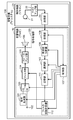
- FIG. 3 is a block diagram schematically illustrating an example of a functional configuration of the acoustic device according to the first embodiment.
- FIG. 4 is a flowchart illustrating an operation example of the frequency characteristic correction process executed by the acoustic device according to the first embodiment.
- FIG. 5 is a diagram for explaining each chord of Cdim7, C # dim7, and Ddim7.
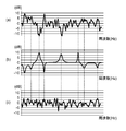
- FIG. 6 is a diagram conceptually illustrating frequency characteristic correction executed by the acoustic device according to the first embodiment.
- FIG. 1 is a diagram for explaining a problem when the acoustic device according to Embodiment 1 is installed indoors.
- FIG. 2 is a diagram schematically showing an outline of the operation of the audio device in the first embodiment.
- FIG. 7 is a diagram schematically illustrating frequency characteristics of an example (5 octaves) of a test sound generated by the acoustic device according to the third modification of the first embodiment.
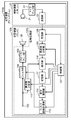
- FIG. 8 is a block diagram schematically illustrating an example of a functional configuration of the acoustic device according to the second embodiment.
- FIG. 1 is a diagram for explaining a problem when the acoustic device 10 according to Embodiment 1 is installed indoors.
- FIG. 2 is a diagram schematically showing an outline of the operation of the acoustic device 10 according to the first embodiment.
- the acoustic device 10 is a television receiver (hereinafter abbreviated as “TV” or “TV”), but the acoustic device 10 may be another device having an acoustic function. .
- the user 30 can output a sound output unit 106 of the acoustic device 10 (or a bass unit provided on the back of the acoustic device 10.
- the direct sound 201 from the sound output unit 106a) is received.
- the user 30 also reflects a primary reflected sound 202 (a sound reflected once by a wall surface or the like and heard by the user 30) and a secondary reflected sound 203 (a sound reflected twice by a wall surface or the like by the user). 30) and the like.
- part of the sound from the sound output unit 106 is transmitted through the indoor space 200 to the outside as the transmitted sound 204.
- part of the sound from the sound output unit 106 may be diffracted sound 205 (sound that is diffracted and received by the user 30). That is, the characteristic (frequency characteristic) of the sound that the user listens to varies depending on the environment in which the acoustic device 10 is installed, the installation position of the acoustic device 10, and the like.
- a dedicated microphone for monitoring
- the test is output from the acoustic device.
- a technique for collecting and monitoring sound with a microphone is used.
- the frequency characteristic of the sound output from the acoustic device is corrected based on the frequency characteristic of the test sound monitored by the microphone installed at the listening position of the user 30. It can be carried out. Therefore, the frequency characteristic of the sound that the user 30 listens at the listening position can be brought close to the desired frequency characteristic.
- white noise or TSP (Time Stretched Pulse) sound (so-called TSP signal) or the like is generally output from a speaker as a test sound.
- TSP signal Time Stretched Pulse
- these sounds may be felt as annoying noise sounds.
- the user 30 will listen to these test sounds when correcting the frequency characteristics of the sound, the user 30 may feel uncomfortable.
- a dedicated microphone is required for correcting the frequency characteristics of the sound.
- the inventors use the 12-scale sound (C, C #, D, D #, E, F, F #, G, G #) constituting one octave as the test sound.
- A, A #, and B) are output from the acoustic device 10.
- the acoustic device 10 can correct the frequency characteristic while reducing the discomfort given to the user 30.
- the inventors have a configuration in which the sound collection unit 21 used for voice recognition included in the control device 20 (the remote controller in the first embodiment) that controls the acoustic device 10 is used to acquire the test sound. I found it. Thereby, the acoustic device 10 can correct the frequency characteristics without using a dedicated microphone.
- acoustic device 100 including the acoustic device 10 and the control device 20 will be described.
- FIG. 3 is a block diagram schematically illustrating an example of a functional configuration of the audio device 100 according to the first embodiment.
- the acoustic device 10 is a television and the acoustic device 100 is a TV system.
- the acoustic device 10 and the acoustic device 100 may be other devices having an acoustic function.
- the audio device 100 (TV system) includes an audio device 10 (television) and a control device 20 (remote controller). First, the configuration of the audio device 10 will be described.
- the acoustic device 10 is a device that outputs sound that the user 30 listens to.
- the description regarding the general function as a television is abbreviate
- the acoustic device 10 includes a sound output unit 106 and a signal processing unit 120. More specifically, the acoustic device 10 includes a signal generation unit 101, a signal acquisition unit 102, a switching unit 103, a filter unit 104, a speaker amplifier unit 105, a sound output unit 106, a control unit 107, and a reception unit. Unit 108, frequency analysis unit 109, selection unit 110, storage unit 111, and filter coefficient calculation unit 112.
- the signal processing unit 120 includes a signal generation unit 101, a signal acquisition unit 102, a switching unit 103, a filter unit 104, a speaker amplifier unit 105, a control unit 107, a reception unit 108, a frequency analysis unit 109, a selection unit 110, a storage unit 111, And a filter coefficient calculation unit 112.
- the signal generator 101 generates a test signal based on the control from the controller 107.
- the test signal is a signal for outputting a test sound.
- the test sound is a plurality of types of chords each consisting of a part of a 12-scale sound.
- the test sound is, for example, three chords Cdim7, C # dim7, and Ddim7, but may be other chords.
- the signal generation unit 101 generates a test signal for outputting such a test sound.
- the signal generation unit 101 is realized by a circuit (signal generation circuit), for example, but may be realized by a processor.
- the test sound is, for example, an electronic sound generated by a combination (superposition) of sine waves.
- an actual musical instrument sound or a MIDI (Musical Instrument Digital Interface) sound source may be used as the test sound.
- the signal generation unit 101 may generate a test sound that has been fade-in processed or faded-out.
- the speaker amplifier unit 105 may perform a fade-in process or a fade-out process on the test signal generated by the signal generation unit 101.
- the signal acquisition unit 102 acquires an acoustic signal.
- the acoustic signal is a signal for outputting, for example, television sound.
- the switching unit 103 selectively switches which of the test signal generated by the signal generation unit 101 and the acoustic signal obtained through the signal acquisition unit 102 is output to the filter unit 104 based on the control of the control unit 107.
- the switching unit 103 is realized by a circuit (switching circuit), for example, but may be realized by a processor.
- the filter unit 104 performs a filtering process using the filter coefficient calculated by the filter coefficient calculation unit 112 on the acoustic signal output from the switching unit 103. That is, the filter unit 104 corrects the frequency characteristic of the sound output from the sound output unit 106 by the filter coefficient by the filter coefficient calculation unit 112.
- the filter unit 104 is realized by a circuit (filter circuit), for example, but may be realized by a processor.
- the speaker amplifier unit 105 amplifies the test signal or the acoustic signal subjected to the filter process and outputs the amplified signal to the sound output unit 106.
- the speaker amplifier unit 105 is realized by a circuit (speaker amplifier circuit), for example.
- the sound output unit 106 outputs a test sound corresponding to the amplified test signal output from the speaker amplifier unit 105. Further, the sound output unit 106 outputs a sound corresponding to the amplified acoustic signal output from the speaker amplifier unit 105.
- the sound output unit 106 is specifically a speaker.
- the reception unit 108 receives a signal transmitted from the transmission unit 23 of the control device 20. Then, when receiving the test sound acquisition result (signal indicating the acquisition result) from the transmission unit 23 of the control device 20, the reception unit 108 outputs the received acquisition result to the frequency analysis unit 109. In addition, when receiving a control signal for controlling the audio device 10 from the transmission unit 23 of the control device 20, the reception unit 108 outputs the received control signal to the control unit 107.
- the reception unit 108 receives a signal (the acquisition result and the control signal) transmitted from the transmission unit 23 of the control device 20 by wireless communication.
- wireless communication for wireless communication in this case, for example, wireless communication standards such as Bluetooth (registered trademark), Wi-Fi (registered trademark), Zigbee (registered trademark) may be used, or infrared communication or the like may be used. Also good.
- the receiving unit 108 may be realized by a wireless communication module (communication circuit), for example.
- the control unit 107 corrects the frequency characteristic of the sound output from the sound output unit 106 based on the received acquisition result.
- the control unit 107 controls the reception unit 108, the frequency analysis unit 109, the selection unit 110, the storage unit 111, the filter coefficient calculation unit 112, the signal generation unit 101, the switching unit 103, and the filter unit 104 to correct frequency characteristics. I do.
- control unit 107 analyzes the received control signal and performs various processes (channel change, volume change, etc.) according to the analysis result.
- the control signal may include a sound signal based on a sound uttered by the user 30 in order to perform a sound operation on the acoustic device 10. Therefore, an existing speech recognition technique may be used for the analysis performed by the control unit 107 at this time.
- the control unit 107 is realized by a circuit (control circuit), for example, but may be realized by a processor.
- the frequency analysis unit 109 Based on the control from the control unit 107, the frequency analysis unit 109 performs an FFT (Fast Fourier Transform) process on the test sound acquisition result received by the reception unit 108. As a result of the FFT processing, the test sound acquisition result is converted into a power value for each frequency.
- the frequency analysis unit 109 is realized by a circuit (frequency analysis circuit), for example, but may be realized by a processor.
- the selection unit 110 selects the main frequency included in the test sound output from the sound output unit 106 and the power value of the frequency from the acquisition results after the FFT processing, and selects the selected frequency and the power of the frequency.
- the value is stored in the storage unit 111.
- Cdim7 composed of single sounds of C (261.6 Hz), D # (311.1 Hz), F # (370.0 Hz), and A (440.0 Hz) is output from the sound output unit 106.
- the selection unit 110 selects these frequencies and the power value of the frequency included in the acquisition result after the FFT process, and stores the selection result in the storage unit 111.
- the selection unit 110 is realized by a circuit (selection circuit), for example, but may be realized by a processor.
- the storage unit 111 is a storage device that stores the frequency selected by the selection unit 110 and the power value of the frequency.
- the storage unit 111 also stores ideal frequency characteristics (predetermined frequency characteristics) in design.
- the storage unit 111 is realized by, for example, a semiconductor memory.
- the filter coefficient calculation unit 112 includes a power value stored in the storage unit 111 (power value of the main frequency of the test sound), a design frequency characteristic (ideal frequency characteristic) stored in the storage unit 111, Is read from the storage unit 111.
- the filter coefficient calculation unit 112 compares the read acquisition result (power value) with the designed frequency characteristic (ideal frequency characteristic) and compares the test sound acquisition result (power value) with the designed frequency characteristic. Calculate filter coefficients to approximate (ideal frequency characteristics).
- the filter coefficient includes a gain, a Q value, a center value (Fc) of a frequency at which gain is increased or decreased, and the like.
- the calculation result (filter coefficient) in the filter coefficient calculation unit 112 is output from the filter coefficient calculation unit 112 to the filter unit 104.
- the filter coefficient calculation unit 112 is realized by a circuit (filter coefficient calculation circuit), for example, but may be realized by a processor.
- the control device 20 is a device that the user 30 operates to control the audio device 10.
- the control device 20 is a television remote controller, for example, but may be another device such as a smartphone or a tablet terminal.
- the control device 20 includes a sound collection unit 21, a microphone amplifier unit 22, and a transmission unit 23.
- a description of a general function as a TV remote controller is omitted.
- the remote controller is abbreviated as “remote controller”.
- the sound collection unit 21 acquires sounds around the control device 20 including the voice of the user 30 and outputs a sound signal (raw sound data) corresponding to the acquired sounds.
- the sound collection unit 21 acquires the test sound output from the sound output unit 106 and outputs an acquisition result (sound signal).
- the sound collection unit 21 is a microphone.
- the microphone amplifier unit 22 amplifies the sound signal output from the sound collection unit 21 and outputs the amplified sound signal to the transmission unit 23.
- the microphone amplifier unit 22 is realized by a circuit (microphone amplifier circuit), for example.
- the transmission unit 23 is an example of a control signal transmission unit.
- the transmission unit 23 transmits a control signal for controlling the acoustic device 10 based on a user operation to the acoustic device 10.
- the user operation includes a voice operation by voice generated by the user 30 to operate the acoustic device 10 by voice.
- the control signal includes a signal based on the voice of the user 30 uttered by the user 30 for voice operation and acquired by the sound pickup unit 21. That is, the transmission unit 23 transmits the sound signal output from the sound collection unit 21 according to the voice of the user 30 and amplified by the microphone amplifier unit 22 to the reception unit 108 of the acoustic device 10 as a control signal. Send.
- the transmission unit 23 is also an example of an acquisition result transmission unit.
- the transmission unit 23 transmits a signal indicating the test sound acquisition result by the sound collection unit 21 to the acoustic device 10. More specifically, the transmission unit 23 is a sound signal output from the sound collection unit 21 according to the test sound (the test sound output from the sound output unit 106) and is amplified by the microphone amplifier unit 22. The signal is transmitted to the receiving unit 108 of the acoustic device 10 as a signal indicating the result of acquiring the test sound.
- the transmission unit 23 transmits a test sound acquisition result and a control signal by the sound collection unit 21 by wireless communication.
- wireless communication for wireless communication in this case, for example, wireless communication standards such as Bluetooth (registered trademark), Wi-Fi (registered trademark), Zigbee (registered trademark) may be used, or infrared communication or the like may be used. Also good.
- the transmission part 23 may be implement
- FIG. 4 is a flowchart showing an operation example of frequency characteristic correction processing executed by the acoustic device 100 according to the first embodiment.
- the sound output unit 106 outputs a test sound (step S11).
- control unit 107 causes the signal generation unit 101 to generate a test signal. Further, the control unit 107 switches the switching unit 103 so that the test signal from the signal generation unit 101 is input to the filter unit 104. As a result of this control, a test signal from the signal generation unit 101 is input to the speaker amplifier unit 105 through the filter unit 104.
- the filter unit 104 may pass the test signal without correction.
- the speaker amplifier unit 105 amplifies the test signal to a predetermined level, and outputs the amplified test signal to the sound output unit 106. As a result, a test sound is output from the sound output unit 106.
- the predetermined level is a level (size) at which the sound collection unit 21 of the control device 20 arranged at the listening position of the user 30 can appropriately acquire the test sound.
- the test sound is composed of three chords Cdim7, C # dim7, and Ddim7 (three kinds of reduced seven chords each having C, C #, and D as root sounds). ).
- the sound output unit 106 outputs these three chords in an arbitrary order.
- the three chords Cdim7, C # dim7, and Ddim7 are all chords composed of four single notes, and the four single notes have different pitches by one and a half tone.
- FIG. 5 is a diagram for explaining each chord of Cdim7, C # dim7, and Ddim7.
- Cdim7 is composed of four single sounds of C (261.6 Hz), D # (311.1 Hz), F # (370.0 Hz), and A (440.0 Hz). Consists of Also, as shown in FIG. 5B, C # dim7 is C # (277.2 Hz), E (329.6 Hz), G (392.0 Hz), and A # (466.2 Hz), It consists of four single notes. Further, as shown in FIG. 5C, Ddim7 has four values of D (293.7 Hz), F (349.2 Hz), G # (415.3 Hz), and B (493.9 Hz). Consists of single notes.
- the sound output unit 106 when the sound output unit 106 is configured to output each chord of Cdim7, C # dim7, and Ddim7, the sound output unit 106 outputs all of the 12 scales within one octave by outputting the chord three times.
- the sound can be output in a comprehensive manner. Therefore, the acoustic device 100 can reduce the uncomfortable feeling (or uncomfortable feeling) given to the user 30 as compared with the configuration in which the noise sound as in the related art is output as the test sound. Moreover, the acoustic device 100 can output the test sound efficiently in a relatively short time.
- the sound of 12 scales is not limited to the sound which belongs to the above-mentioned range of 261.6 Hz or more and 493.9 Hz or less.
- a sound of 12 scales belonging to a range of 523.3 Hz or more and 987.76 Hz or less one octave higher than this range may be output from the sound output unit 106, or 12 scales of an octave higher than this range may be output.
- Sound may be output from the sound output unit 106.
- the frequencies of the 12 scale sounds output from the sound output unit 106 may be appropriately selected according to the frequency range to be corrected.
- the timing at which the three chords are output from the sound output unit 106 is not particularly limited. For example, after the first chord is output from the sound output unit 106 and the power value of the frequency of the first chord is stored in the storage unit 111, the second chord is output from the sound output unit 106, The order may be such that after the power value of the frequency of the second chord is stored in the storage unit 111, the third chord is output from the sound output unit 106. Whether or not the power value of the frequency of the first (or second) chord is stored in the storage unit 111 is, for example, whether or not the control unit 107 stores a predetermined amount of data in the storage unit 111. This may be determined by detecting (buffer full detection).
- a silence period may be interposed between the first chord and the second chord (or between the second chord and the third chord).
- the selection unit 110 can detect the silence period and start storing the power value (buffer fetch) in the storage unit 111.
- the selection unit 110 may detect the level after completion of the fade-in and start storing the power value in the storage unit 111.
- the acoustic device 10 notifies the control device 20 in advance using wireless communication (from the acoustic device 10 to the control device 20 that the test sound will be output from now on). Notification may be performed), and the gain of the microphone amplifier unit 22 may be changed to a gain (preset gain) for acquiring the test sound by performing the prior notification.
- the sound collection unit 21 of the control device 20 acquires the test sound (step S12).
- the sound collection unit 21 outputs the acquisition result (sound signal) to the microphone amplifier unit 22.
- the acquisition result (sound signal) is amplified by the microphone amplifier unit 22.
- the transmission unit 23 of the control device 20 transmits the amplified acquisition result to the reception unit 108 of the audio device 10 (step S13).
- the acquisition result transmitted from the transmission unit 23 is received by the reception unit 108.
- the signal processing unit 120 of the acoustic device 10 corrects the frequency characteristics of the sound output from the sound output unit 106 based on the acquisition result received by the reception unit 108 (step S14).
- step S14 The correction performed in step S14 will be described with reference to FIG.
- FIG. 6 is a diagram conceptually illustrating the correction of the frequency characteristic performed by the acoustic device 100 according to the first embodiment.
- the horizontal axis represents the frequency
- the vertical axis represents the volume of the sound (relative volume with the reference volume being 0 (dB)).
- FIG. 6A is a diagram illustrating an example of frequency characteristics before correction at the listening position of the user 30.
- FIG. 6B is a diagram illustrating an example of frequency characteristics based on filter coefficients calculated by the filter coefficient calculation unit 112.
- FIG. 6C is a diagram illustrating an example of the corrected frequency characteristic at the listening position of the user 30.
- the ideal frequency characteristic is a flat frequency characteristic (a state in which there is no variation in sound volume for each frequency), in FIG. It is desirable to correct the portions that are present.
- the filter coefficient calculation unit 112 calculates a filter coefficient that gives a frequency characteristic as shown as an example in FIG. That is, the filter coefficient calculation unit 112 is configured so that the sound is reduced with respect to the frequency that protrudes upward from 0 (dB) in FIG. 6A (that is, the sound is relatively loud). ), The filter coefficient is calculated so that the sound becomes louder with respect to the frequency that protrudes downward from 0 (dB) (that is, the sound is relatively small).
- the filter part 104 performs the filter process which gives the frequency characteristic shown to (b) of FIG. 6 to the audio
- the frequency characteristic in the listening position of the user 30 is, for example, 6, the frequency characteristic before correction shown in FIG. 6A is corrected to the frequency characteristic shown in FIG. 6C, that is, a flatter frequency characteristic compared with the frequency characteristic before correction. .
- the acoustic device 10 can bring the corrected frequency characteristic at the listening position of the user 30 closer to an ideal frequency characteristic (for example, a flat frequency characteristic).
- an ideal frequency characteristic for example, a flat frequency characteristic
- the ideal frequency characteristic may be stored in the storage unit 111 in advance. Further, the acoustic device 10 may be configured such that an ideal frequency characteristic can be arbitrarily set by the user 30 operating the control device 20 or the like.
- the filter coefficient calculation unit 112 also sets a frequency characteristic set in advance as an ideal frequency characteristic, a frequency characteristic before correction at the listening position of the user 30, and a frequency characteristic correction start instruction from the user 30 (control device 20 The filter coefficient may be calculated according to the correction start instruction by the user 30 performed via
- the acoustic device includes the acoustic device and the control device.
- the control device includes a sound collection unit and a control signal transmission unit.
- the sound collection unit acquires sounds around the control device including the user's voice.
- the control signal transmission unit transmits a control signal for controlling the acoustic device to the acoustic device based on the user's voice acquired by the sound collection unit.
- the acoustic device includes a sound output unit and a signal processing unit.
- the signal processing unit causes the sound output unit to output each of the 12 scale sounds constituting one octave as a test sound to be acquired by the sound collection unit in order to correct the frequency characteristics of the sound output from the sound output unit. .
- the correction method in the present embodiment is a correction method executed by an audio device including an audio device having a sound output unit and a control device.
- the control device transmits to the acoustic device a sound collection unit that acquires sounds around the control device including the user's voice, and a control signal for controlling the acoustic device based on the user's voice acquired by the sound collection unit.
- This correction method is a method for correcting the frequency characteristics of the sound output from the sound output section, and corrects the frequency characteristics of the sound output from the sound output section for each of the 12 scale sounds constituting one octave. And a step of outputting to the sound output unit as a test sound to be acquired by the sound collection unit.
- the sound collection unit of the control device may acquire the test sound output from the sound output unit of the audio device.
- the control device may further include an acquisition result transmission unit that transmits an acquisition result of the test sound by the sound collection unit to the acoustic device.
- the signal processing unit of the audio device may receive the acquisition result transmitted by the acquisition result transmitting unit, and correct the frequency characteristics of the sound output from the sound output unit based on the received acquisition result.
- the acoustic device 100 is an example of an acoustic device.
- the audio device 10 is an example of an audio device.
- the control device 20 is an example of a control device.
- the sound collection unit 21 is an example of a sound collection unit.
- the transmission unit 23 is an example of a control signal transmission unit, and is also an example of an acquisition result transmission unit.
- the sound output unit 106 is an example of a sound output unit.
- the signal processing unit 120 is an example of a signal processing unit.
- the acoustic device 100 includes the acoustic device 10 and the control device 20.
- the control device 20 includes a sound collection unit 21 and a transmission unit 23.
- the sound collection unit 21 acquires sounds around the control device 20 including the voice of the user 30.
- the transmission unit 23 transmits a control signal for controlling the acoustic device 10 to the acoustic device 10 based on the voice of the user 30 acquired by the sound collection unit 21.
- the acoustic device 10 includes a sound output unit 106 and a signal processing unit 120.
- the signal processing unit 120 uses the sound output unit as a test sound to be acquired by the sound collection unit 21 in order to correct the frequency characteristics of the sound output from the sound output unit 106 for each of the 12 scale sounds constituting one octave. 106 to output.
- the sound collection unit 21 of the control device 20 acquires the test sound output from the sound output unit 106 of the audio device 10.
- the transmission unit 23 of the control device 20 transmits the acquisition result of the test sound by the sound collection unit 21 to the acoustic device 10.
- the signal processing unit 120 of the acoustic device 10 receives the acquisition result transmitted by the transmission unit 23 and corrects the frequency characteristics of the sound output from the sound output unit 106 based on the received acquisition result.
- the 12-scale sound output as the test sound may be output in such a manner that the user 30 can distinguish and recognize the sound of each scale.
- the test sound is not an exciting (unpleasant) sound compared to the white noise and the TSP sound.
- the discomfort given to the user 30 can be reduced.
- the acoustic device 100 can acquire information of at least 12 scales (12 spectra) (power value of the frequency of each sound of 12 scales), the frequency characteristic can be appropriately corrected. That is, the acoustic device 100 can correct the frequency characteristics while reducing discomfort given to the user 30.
- the acoustic device 100 since a sound having a specific frequency (for 12 scales) is used as a test sound, the amount of information stored for calculating the filter coefficient (the power for each frequency stored in the storage unit 111) The number of values) is smaller than when white noise is used as the test sound. That is, the acoustic device 100 can reduce storage resources (storage capacity necessary for calculating the filter coefficient, for example, storage capacity of the storage unit 111).
- information is equivalent to information (frequency of each sound of 12 scales). If the 12-scale sound is used as the test sound, the test sound volume is set to be lower than the case where white noise is used as the test sound. Can be small. In other words, when test sounds are output at the same volume, the S / N ratio is higher when a 12-scale sound is used as the test sound than when white noise is used as the test sound. Information (power value of the frequency of each sound of 12 scales) can be obtained.
- the signal processing unit included in the acoustic device may sequentially output each of a plurality of types of chords each consisting of a part of a 12-scale sound to the sound output unit as a test sound.
- Each of Cdim7, C # dim7, and Ddim7 is an example of a chord made up of a part of a 12-scale sound.
- the signal processing unit included in the audio device may sequentially output each of Cdim7, C # dim7, and Ddim7 to the sound output unit as a test sound.
- the signal processing unit 120 of the audio device 100 causes the sound output unit 106 to sequentially output Cdim7, C # dim7, and Ddim7 as test sounds.
- the sound output unit 106 when the sound output unit 106 outputs three types of chords Cdim7, C # dim7, and Ddim7, the sound output unit 106 outputs 12 chords within one octave only by outputting the chord three times. It can output all sounds of.
- the frequency characteristic is measured by sweeping the frequency (ie, gradually changing the frequency from low to high or from high to low)
- the frequency characteristics can be measured efficiently in a shorter time.
- a single note of the same scale may be output from the sound output unit 106 in duplicate.
- the signal processing unit 120 the power value of the frequency of the overlapping single sound may be normalized and used.
- a component for normalization (for example, a normalization circuit) may be provided between the selection unit 110 and the storage unit 111, for example.
- the signal processing unit 120 is either an average power value, a maximum value, a minimum value, or a median value of the frequency of the overlapping single sound. May be used as the power value of the frequency of the single tone.
- the signal generation unit 101 may adjust the phase of a single tone constituting the chord to lower the peak value of the sound waveform when viewed on the time axis. Thereby, the occurrence of overflow can be suppressed.
- the signal processing unit 120 may cause the sound output unit 106 to output a melody composed of a single sound (or composed of a single sound and a chord) instead of a chord as a test sound. That is, the signal processing unit 120 may cause the sound output unit 106 to sequentially output each of the 12 scale sounds as test sounds. Alternatively, the signal processing unit 120 may cause the sound output unit 106 to output each of the 12 scale sounds as test sounds in the order in which a predetermined melody is played. Also in this case, when a single note of the same scale is output in duplicate, the signal processing unit 120 may perform the above normalization or the like. Further, in the acoustic device 100, when a melody consisting of a single sound is used as a test sound, the output of the test sound from the sound output unit 106 may be continued until each of the 12 scale sounds is output.
- the frequency power values calculated by the frequency analysis unit 109 may be integrated (merged). For example, when the resolution per octave is reduced to 6, the signal processing unit 120 divides the power values of the frequencies of the 12 scales calculated by the frequency analysis unit 109 into 6 sets of 2 scales, The power values may be averaged for each set. And the signal processing part 120 may correct
- the signal generation unit 101 may generate a test sound in which each of the 12 scale sounds is vibrato (with a wide frequency). In this case, the selection of the frequency by the selection unit 110 may be omitted.
- the signal processing unit 120 may cause the sound output unit 106 to sequentially output Cdim7, C # dim7, and Ddim7 over a plurality of octaves as test sounds. For example, the signal processing unit 120 may cause the sound output unit 106 to sequentially output each of Cdim7, C # dim7, and Ddim7 over five octaves as a test sound.
- FIG. 7 is a diagram schematically illustrating frequency characteristics of an example of test sound (5 octaves) generated by the acoustic device 100 according to the third modification of the first embodiment.
- the horizontal axis represents frequency
- the vertical axis represents sound volume.
- FIG. 7 is a diagram showing the frequency characteristics of Cdim7 over 5 octaves.
- FIG. 7B is a diagram illustrating the frequency characteristics of C # dim7 over 5 octaves.
- (C) of FIG. 7 is a figure which shows the frequency characteristic of Ddim7 over 5 octaves.
- the acoustic device 100 outputs a chord over a plurality of octaves (for example, 5 octaves) as a test signal, thereby significantly reducing the output time of the test sound (1 / octave number, for example, 1 / octave 5).
- octaves for example, 5 octaves
- the present disclosure is not limited to this configuration.
- the control device 20 may calculate a filter coefficient and transmit the filter coefficient from the transmission unit 23 to the reception unit 108 of the audio device 10.
- the control device 20 includes components (for example, frequency analysis) having functions similar to those of the frequency analysis unit 109, the selection unit 110, the storage unit 111, and the filter coefficient calculation unit 112 included in the audio device 10.
- the control device 20 amplifies the sound signal output from the sound collection unit 21 by the microphone amplifier unit 22. Based on the amplified sound signal, the control device 20 calculates a filter coefficient using a frequency analysis unit, a selection unit, a storage unit, and a filter coefficient calculation unit included in the control device 20, and transmits the filter coefficient to the transmission unit 23. Output to.
- the filter coefficient is transmitted from the transmission unit 23 of the control device 20 to the reception unit 108 of the signal processing unit 120 and received by the reception unit 108. Then, the signal processing unit 120 sets the filter coefficient received by the receiving unit 108 in the filter unit 104.
- the amount of data transmitted from the control device 20 to the audio device 10 can be significantly reduced as compared with the configuration example shown in the first embodiment.
- test signal is generated by the signal generation unit 101 of the acoustic device 100
- the present disclosure is not limited to this configuration.
- an acoustic signal (a signal for outputting TV sound or the like) obtained through the signal acquisition unit 102 may be used as the test signal.
- television sound may be used as the test sound.
- an acoustic device 100a configured to use an acoustic signal obtained through the signal acquisition unit 102 as a test signal will be described.
- FIG. 8 is a block diagram schematically illustrating an example of a functional configuration of the acoustic device 100a according to the second embodiment.
- acoustic device 100a shown in the second embodiment components that operate substantially the same as the components included in the acoustic device 100 shown in the first embodiment are given the same reference numerals as the components, Description is omitted.
- description will be made centering on differences from the acoustic device 100 described in the first embodiment, and description of operations that are substantially the same as those of the acoustic device 100 described in the first embodiment may be omitted. .
- the audio device 100a (for example, a TV system) includes an audio device 10a (for example, a television) and a control device 20 (for example, a remote controller).
- the acoustic device 10a includes a sound output unit 106 and a signal processing unit 120a.
- the acoustic device 100a has substantially the same configuration as the acoustic device 100 shown in the first embodiment, and performs substantially the same operation.
- the acoustic device 10a included in the acoustic device 100a is different from the acoustic device 10 described in Embodiment 1 in that the acoustic device 10a does not include the signal generation unit 101 and the switching unit 103 but includes the frequency analysis unit 113 and the difference calculation unit 114. .
- the signal processing unit 120a of the acoustic device 10a includes a signal acquisition unit 102, a filter unit 104, a speaker amplifier unit 105, a control unit 107, a reception unit 108, a frequency analysis unit 109, a selection unit 110, a storage unit 111, and filter coefficient calculation.
- Unit 112, frequency analysis unit 113, and difference calculation unit 114 includes a signal acquisition unit 102, a filter unit 104, a speaker amplifier unit 105, a control unit 107, a reception unit 108, a frequency analysis unit 109, a selection unit 110, a storage unit 111, and filter coefficient calculation.
- Unit 112 frequency analysis unit 113, and difference calculation unit 114.
- the frequency analysis unit 113 performs an FFT process on the acoustic signal obtained through the signal acquisition unit 102 based on the control from the control unit 107. As a result, the acoustic signal after FFT processing (analysis result of the acoustic signal) is expressed by a power value for each frequency. Further, the frequency analysis unit 113 outputs the acoustic signal after the FFT processing (analysis result of the acoustic signal) to the selection unit 110.
- the frequency analysis unit 113 is realized by a circuit (frequency analysis circuit), for example, but may be realized by a processor.
- the selection unit 110 selects the frequency of each of the 12 scale sounds and the power value of the frequency from the analysis result of the acoustic signal, and stores the selected frequency and the power value of the frequency in the storage unit 111. To do.
- the sound by the acoustic signal analyzed by the frequency analysis unit 113 is output from the sound output unit 106 as television sound, for example.
- a sound for example, TV sound
- a sound obtained from the sound signal obtained through the signal acquisition unit 102 is used as the test sound. Used.
- Sound output from the sound output unit 106 (for example, television sound as a test sound) is acquired by the sound collection unit 21 of the control device 20. Then, the sound acquisition result by the sound collection unit 21 is transmitted from the transmission unit 23 of the control device 20 to the reception unit 108 of the acoustic device 10a and received by the reception unit 108 in the same manner as in the first embodiment.
- the analysis unit 109 performs FFT processing.
- the selection unit 110 selects each frequency of the 12th scale sound and the power value of the frequency from the acquisition results after the FFT processing, and stores the selected frequency and the power value of the frequency in the storage unit 111. To do.
- the difference calculation unit 114 refers to the storage unit 111 and is included in the power value included in the acoustic signal analysis result (analysis result by the frequency analysis unit 113) and the acquisition result (analysis result by the frequency analysis unit 109). The difference between the power values is compared with the power value for each frequency to calculate the difference between the power values, and the calculation result is output to the filter coefficient calculation unit 112.
- the difference calculation unit 114 is realized by a circuit (difference calculation circuit), for example, but may be realized by a processor.
- the filter coefficient calculation unit 112 calculates a filter coefficient such that the difference value calculated by the difference calculation unit 114 is equal to or less than a predetermined value (for example, ⁇ 1 dB).
- the filter unit 104 performs a filtering process using the filter coefficient calculated by the filter coefficient calculation unit 112 on the acoustic signal obtained through the signal acquisition unit 102.
- the filter unit 104 corrects the frequency characteristic of the acoustic signal obtained through the signal acquisition unit 102 with the filter coefficient by the filter coefficient calculation unit 112.
- the acoustic device 100a uses an acoustic signal (a signal for outputting television sound or the like) obtained through the signal acquisition unit 102 as a test signal. That is, the audio device 100a uses television sound as the test sound.
- the acoustic device 100a can correct the frequency characteristic in a natural manner without giving the user 30 a sense of incongruity.
- the frequency characteristic correction processing performed by the acoustic device 100a is continued until each sound of 12 scales is output from the sound output unit 106 by sound (for example, television sound) by an acoustic signal obtained through the signal acquisition unit 102. May be.
- Embodiments 1 and 2 have been described as examples of the technology disclosed in the present application. However, the technology in the present disclosure is not limited to this, and can also be applied to embodiments in which changes, replacements, additions, omissions, and the like are performed. Moreover, it is also possible to combine each component demonstrated in the said Embodiment 1, 2 and it can also be set as a new embodiment.
- Embodiments 1 and 2 have described examples in which the technology of the present disclosure is applied to a TV system.
- the technology in the present disclosure can be applied to, for example, an in-vehicle audio device or an in-vehicle navigation device having a hands-free (voice recognition) function.
- the technology in the present disclosure can also be applied to, for example, an audio device (mini component, AV (Audio Visual) center amplifier, etc.).
- the operation example in which the gain of the microphone amplifier unit 22 is adjusted when the sound output unit 106 outputs the test sound has been described.
- the gain of the speaker amplifier unit 105 is adjusted Good.
- each component may be configured by dedicated hardware, or realized by a software program configured to realize the function of each component being executed by a processor. May be. That is, each component may be realized by a program execution unit such as a CPU (Central Processing Unit) or a processor reading and executing a software program recorded on a recording medium such as a hard disk or a semiconductor memory.
- a program execution unit such as a CPU (Central Processing Unit) or a processor reading and executing a software program recorded on a recording medium such as a hard disk or a semiconductor memory.
- the comprehensive or specific aspect of the technology in the present disclosure may be realized by a system, a method, an integrated circuit, a computer program, or a computer-readable recording medium (for example, an optical disc or a semiconductor memory). Good. Further, the technology in the present disclosure may be realized by a system, a method, an integrated circuit, a computer program, or any combination of recording media. For example, the technology in the present disclosure may be realized as a frequency characteristic correction method executed by the acoustic device.
- the present disclosure is applicable to an audio device that corrects frequency characteristics. Specifically, the present disclosure is applicable to televisions, in-vehicle navigation devices, audio devices, and the like.
Landscapes
- Physics & Mathematics (AREA)
- Engineering & Computer Science (AREA)
- Acoustics & Sound (AREA)
- Signal Processing (AREA)
- Multimedia (AREA)
- General Physics & Mathematics (AREA)
- Circuit For Audible Band Transducer (AREA)
- Measurement Of Mechanical Vibrations Or Ultrasonic Waves (AREA)
Abstract
L'invention concerne un dispositif acoustique apte à réduire une gêne causée à un utilisateur relativement à la correction de propriétés de fréquence, en utilisant des sons de test. Le dispositif acoustique comporte une machine acoustique et une machine de commande. La machine de commande a une unité d'acquisition de son et une unité de transmission de signal de commande. L'unité d'acquisition de son acquiert des sons dans la périphérie de la machine de commande comprenant la voix de l'utilisateur. L'unité de transmission de signal de commande transmet, à la machine acoustique, un signal de commande pour commander la machine acoustique sur la base de la voix de l'utilisateur acquise par l'unité d'acquisition de son. La machine acoustique a une unité de sortie de son et une unité de traitement de signal. L'unité de traitement de signal amène l'unité de sortie de son à délivrer chaque son, dans une échelle à douze notes constituant une octave, sous la forme d'un son de test qui doit être acquis par l'unité d'acquisition de son, de façon à corriger les propriétés de fréquence de sons délivrés par l'unité de sortie de son.
Applications Claiming Priority (2)
| Application Number | Priority Date | Filing Date | Title |
|---|---|---|---|
| JP2015-050075 | 2015-03-12 | ||
| JP2015050075A JP2018072359A (ja) | 2015-03-12 | 2015-03-12 | 音響装置及び補正方法 |
Publications (1)
| Publication Number | Publication Date |
|---|---|
| WO2016143276A1 true WO2016143276A1 (fr) | 2016-09-15 |
Family
ID=56879452
Family Applications (1)
| Application Number | Title | Priority Date | Filing Date |
|---|---|---|---|
| PCT/JP2016/000917 Ceased WO2016143276A1 (fr) | 2015-03-12 | 2016-02-22 | Dispositif acoustique et procédé de correction |
Country Status (2)
| Country | Link |
|---|---|
| JP (1) | JP2018072359A (fr) |
| WO (1) | WO2016143276A1 (fr) |
Citations (10)
| Publication number | Priority date | Publication date | Assignee | Title |
|---|---|---|---|---|
| JPH0475498U (fr) * | 1990-11-14 | 1992-07-01 | ||
| JP2003195859A (ja) * | 2001-12-27 | 2003-07-09 | Yamaha Corp | 電子楽音発生装置および信号処理特性調整方法 |
| JP2005012784A (ja) * | 2003-05-26 | 2005-01-13 | Matsushita Electric Ind Co Ltd | 音場測定装置 |
| JP2005303967A (ja) * | 2004-03-17 | 2005-10-27 | Sony Corp | 測定装置、測定方法、プログラム |
| JP2007306275A (ja) * | 2006-05-11 | 2007-11-22 | Sharp Corp | 音響出力装置、テレビジョン受像機 |
| JP2010010823A (ja) * | 2008-06-24 | 2010-01-14 | Toshiba Corp | 音響特性補正方法及び装置 |
| JP2011123376A (ja) * | 2009-12-11 | 2011-06-23 | Canon Inc | 音響処理装置及び方法 |
| JP2012141449A (ja) * | 2010-12-28 | 2012-07-26 | Toshiba Corp | 音声処理装置、音声処理システム及び音声処理方法 |
| JP2013140349A (ja) * | 2011-12-30 | 2013-07-18 | Samsung Electronics Co Ltd | 電子装置及びその制御方法 |
| JP2014115446A (ja) * | 2012-12-10 | 2014-06-26 | Nippon Seiki Co Ltd | 音声認識リモコン |
-
2015
- 2015-03-12 JP JP2015050075A patent/JP2018072359A/ja active Pending
-
2016
- 2016-02-22 WO PCT/JP2016/000917 patent/WO2016143276A1/fr not_active Ceased
Patent Citations (10)
| Publication number | Priority date | Publication date | Assignee | Title |
|---|---|---|---|---|
| JPH0475498U (fr) * | 1990-11-14 | 1992-07-01 | ||
| JP2003195859A (ja) * | 2001-12-27 | 2003-07-09 | Yamaha Corp | 電子楽音発生装置および信号処理特性調整方法 |
| JP2005012784A (ja) * | 2003-05-26 | 2005-01-13 | Matsushita Electric Ind Co Ltd | 音場測定装置 |
| JP2005303967A (ja) * | 2004-03-17 | 2005-10-27 | Sony Corp | 測定装置、測定方法、プログラム |
| JP2007306275A (ja) * | 2006-05-11 | 2007-11-22 | Sharp Corp | 音響出力装置、テレビジョン受像機 |
| JP2010010823A (ja) * | 2008-06-24 | 2010-01-14 | Toshiba Corp | 音響特性補正方法及び装置 |
| JP2011123376A (ja) * | 2009-12-11 | 2011-06-23 | Canon Inc | 音響処理装置及び方法 |
| JP2012141449A (ja) * | 2010-12-28 | 2012-07-26 | Toshiba Corp | 音声処理装置、音声処理システム及び音声処理方法 |
| JP2013140349A (ja) * | 2011-12-30 | 2013-07-18 | Samsung Electronics Co Ltd | 電子装置及びその制御方法 |
| JP2014115446A (ja) * | 2012-12-10 | 2014-06-26 | Nippon Seiki Co Ltd | 音声認識リモコン |
Also Published As
| Publication number | Publication date |
|---|---|
| JP2018072359A (ja) | 2018-05-10 |
Similar Documents
| Publication | Publication Date | Title |
|---|---|---|
| JP2011123376A (ja) | 音響処理装置及び方法 | |
| WO2020125325A1 (fr) | Procédé d'élimination d'écho et dispositif | |
| JP7739348B2 (ja) | 音高に依存しない音色属性をメディア信号から抽出する方法、コンピュータ可読記憶媒体及び装置 | |
| CN114678038A (zh) | 音频噪声检测方法、计算机设备和计算机程序产品 | |
| US20070110129A1 (en) | Method for measuring frequency characteristic and rising edge of impulse response, and sound field correcting apparatus | |
| TWI662544B (zh) | 偵測環境噪音以改變播放語音頻率之方法及其聲音播放裝置 | |
| CN115066912B (zh) | 用于通过装置进行音频渲染的方法、装置和非暂时性计算机可读介质 | |
| WO2019050646A1 (fr) | Détection transitoire pour réduction de distorsion de haut-parleur | |
| CN113348508B (zh) | 电子设备、方法和计算机程序 | |
| WO2007007695A1 (fr) | Système audio | |
| US12621605B2 (en) | Audio playback device, audio playback method thereof and storage medium | |
| JP7427531B2 (ja) | 音響信号処理装置及び音響信号処理プログラム | |
| WO2017135350A1 (fr) | Support d'enregistrement, dispositif de traitement acoustique et procédé de traitement acoustique | |
| JP2012095254A (ja) | 音量調整装置、音量調整方法及び音量調整プログラム並びに音響機器 | |
| JP4275055B2 (ja) | 音質調整装置、放送受信機、プログラム、及び記録媒体 | |
| JP2018072359A (ja) | 音響装置及び補正方法 | |
| JP2008072600A (ja) | 音響信号処理装置、音響信号処理プログラム、音響信号処理方法 | |
| US20230396924A1 (en) | Analysis and optimization of an audio signal | |
| CN110570875A (zh) | 检测环境噪音以改变播放语音频率的方法及声音播放装置 | |
| JP4275054B2 (ja) | 音声信号判別装置、音質調整装置、放送受信機、プログラム、及び記録媒体 | |
| JP4737758B2 (ja) | オーディオ信号処理方法および再生装置 | |
| CN110648686B (zh) | 调整语音频率的方法及其声音播放装置 | |
| WO2023235371A1 (fr) | Analyse et optimisation d'un signal audio | |
| JP4305313B2 (ja) | オーディオ調整パラメータ決定方法およびオーディオ装置 | |
| CN120075673A (zh) | 音频播放方法、装置、存储介质、芯片及耳机 |
Legal Events
| Date | Code | Title | Description |
|---|---|---|---|
| 121 | Ep: the epo has been informed by wipo that ep was designated in this application |
Ref document number: 16761255 Country of ref document: EP Kind code of ref document: A1 |
|
| NENP | Non-entry into the national phase |
Ref country code: DE |
|
| NENP | Non-entry into the national phase |
Ref country code: JP |
|
| 122 | Ep: pct application non-entry in european phase |
Ref document number: 16761255 Country of ref document: EP Kind code of ref document: A1 |