WO2016143457A1 - Système autoexpansible de pose d'endoprothèse - Google Patents
Système autoexpansible de pose d'endoprothèse Download PDFInfo
- Publication number
- WO2016143457A1 WO2016143457A1 PCT/JP2016/054155 JP2016054155W WO2016143457A1 WO 2016143457 A1 WO2016143457 A1 WO 2016143457A1 JP 2016054155 W JP2016054155 W JP 2016054155W WO 2016143457 A1 WO2016143457 A1 WO 2016143457A1
- Authority
- WO
- WIPO (PCT)
- Prior art keywords
- end side
- self
- delivery system
- stent delivery
- distal end
- Prior art date
- Legal status (The legal status is an assumption and is not a legal conclusion. Google has not performed a legal analysis and makes no representation as to the accuracy of the status listed.)
- Ceased
Links
Images


Classifications
-
- A—HUMAN NECESSITIES
- A61—MEDICAL OR VETERINARY SCIENCE; HYGIENE
- A61F—FILTERS IMPLANTABLE INTO BLOOD VESSELS; PROSTHESES; DEVICES PROVIDING PATENCY TO, OR PREVENTING COLLAPSING OF, TUBULAR STRUCTURES OF THE BODY, e.g. STENTS; ORTHOPAEDIC, NURSING OR CONTRACEPTIVE DEVICES; FOMENTATION; TREATMENT OR PROTECTION OF EYES OR EARS; BANDAGES, DRESSINGS OR ABSORBENT PADS; FIRST-AID KITS
- A61F2/00—Filters implantable into blood vessels; Prostheses, i.e. artificial substitutes or replacements for parts of the body; Appliances for connecting them with the body; Devices providing patency to, or preventing collapsing of, tubular structures of the body, e.g. stents
- A61F2/95—Instruments specially adapted for placement or removal of stents or stent-grafts
- A61F2/962—Instruments specially adapted for placement or removal of stents or stent-grafts having an outer sleeve
- A61F2/966—Instruments specially adapted for placement or removal of stents or stent-grafts having an outer sleeve with relative longitudinal movement between outer sleeve and prosthesis, e.g. using a push rod
-
- A—HUMAN NECESSITIES
- A61—MEDICAL OR VETERINARY SCIENCE; HYGIENE
- A61F—FILTERS IMPLANTABLE INTO BLOOD VESSELS; PROSTHESES; DEVICES PROVIDING PATENCY TO, OR PREVENTING COLLAPSING OF, TUBULAR STRUCTURES OF THE BODY, e.g. STENTS; ORTHOPAEDIC, NURSING OR CONTRACEPTIVE DEVICES; FOMENTATION; TREATMENT OR PROTECTION OF EYES OR EARS; BANDAGES, DRESSINGS OR ABSORBENT PADS; FIRST-AID KITS
- A61F2/00—Filters implantable into blood vessels; Prostheses, i.e. artificial substitutes or replacements for parts of the body; Appliances for connecting them with the body; Devices providing patency to, or preventing collapsing of, tubular structures of the body, e.g. stents
- A61F2/82—Devices providing patency to, or preventing collapsing of, tubular structures of the body, e.g. stents
- A61F2/86—Stents in a form characterised by the wire-like elements; Stents in the form characterised by a net-like or mesh-like structure
- A61F2/90—Stents in a form characterised by the wire-like elements; Stents in the form characterised by a net-like or mesh-like structure characterised by a net-like or mesh-like structure
-
- A—HUMAN NECESSITIES
- A61—MEDICAL OR VETERINARY SCIENCE; HYGIENE
- A61F—FILTERS IMPLANTABLE INTO BLOOD VESSELS; PROSTHESES; DEVICES PROVIDING PATENCY TO, OR PREVENTING COLLAPSING OF, TUBULAR STRUCTURES OF THE BODY, e.g. STENTS; ORTHOPAEDIC, NURSING OR CONTRACEPTIVE DEVICES; FOMENTATION; TREATMENT OR PROTECTION OF EYES OR EARS; BANDAGES, DRESSINGS OR ABSORBENT PADS; FIRST-AID KITS
- A61F2/00—Filters implantable into blood vessels; Prostheses, i.e. artificial substitutes or replacements for parts of the body; Appliances for connecting them with the body; Devices providing patency to, or preventing collapsing of, tubular structures of the body, e.g. stents
- A61F2/95—Instruments specially adapted for placement or removal of stents or stent-grafts
- A61F2/9517—Instruments specially adapted for placement or removal of stents or stent-grafts handle assemblies therefor
-
- A—HUMAN NECESSITIES
- A61—MEDICAL OR VETERINARY SCIENCE; HYGIENE
- A61F—FILTERS IMPLANTABLE INTO BLOOD VESSELS; PROSTHESES; DEVICES PROVIDING PATENCY TO, OR PREVENTING COLLAPSING OF, TUBULAR STRUCTURES OF THE BODY, e.g. STENTS; ORTHOPAEDIC, NURSING OR CONTRACEPTIVE DEVICES; FOMENTATION; TREATMENT OR PROTECTION OF EYES OR EARS; BANDAGES, DRESSINGS OR ABSORBENT PADS; FIRST-AID KITS
- A61F2210/00—Particular material properties of prostheses classified in groups A61F2/00 - A61F2/26 or A61F2/82 or A61F9/00 or A61F11/00 or subgroups thereof
- A61F2210/0014—Particular material properties of prostheses classified in groups A61F2/00 - A61F2/26 or A61F2/82 or A61F9/00 or A61F11/00 or subgroups thereof using shape memory or superelastic materials, e.g. nitinol
Definitions
- the present invention relates to a self-expanding stent delivery system.
- Stents are generally used for dilatation treatment of lesion sites such as stenosis and occlusion occurring in living body lumens such as blood vessels, bile ducts, trachea, esophagus and urethra.
- stents There are two types of stents: one that is expanded by a balloon mounted with a stent (balloon expandable stent) and one that expands itself by removing a member that suppresses expansion from the outside (self-expandable stent).
- self-expanding stents are self-expanding when there is no restraint, expansion work like a balloon expandable stent is not necessary.
- Self-expanding stents are more flexible than stents that do not self-expand and can be applied to lesion sites that meander or bend, and are therefore widely used in the medical field.
- a self-expandable stent delivery system for transferring the self-expandable stent to the lesion site may be used.
- Patent Document 1 discloses that a self-expanding stent is housed on the distal end side of a catheter including an inner tube and an outer tube disposed around the inner tube, and is transferred to a living body lumen and fixed to the outer tube.
- the self-expanding stent delivery is deployed by pulling the pulled puller wire to the proximal end by hand operation, moving the outer tube to the proximal end, releasing the self-expanding stent from the catheter and expanding it, and placing it at the lesion site
- a system is disclosed.
- the operation of moving the pulling wire to the distal end side is forcibly restricted, so that the pulling wire cannot be sent out to the distal end side again.
- the pulling wire is pulled while the self-expanding stent is positioned near the placement position, and then the placement position (release position) is adjusted again.
- the pulling wire is returned to the distal end side, the self-expanding stent is re-stored in the outer tube, and the subsequent operation is continued. Such an operation is difficult to realize.
- the present invention has been made to solve the above-described problem, and allows the pulling wire to reversibly move to the distal end side and the proximal end side, thereby improving the operability.
- An object is to provide a stent delivery system.
- the self-expanding stent delivery system according to the present invention that achieves the above object is an inner tube formed with a guide wire lumen through which a guide wire is inserted, and is compressed radially inward when inserted into a living body lumen.
- a self-expanding stent that is arranged around the distal end side of the inner tube and expands outward when it is placed in a living body lumen and can be restored to its original shape before compression, and is disposed on the outer surface side of the inner tube
- the self-expandable stent can be accommodated in the lumen, and the self-expandable stent accommodated in the lumen can be released by moving proximally with respect to the inner tube.
- An outer tube An outer tube, a pulling wire capable of pulling the outer tube to the proximal end side, and an operation unit for operating forward / backward movement of the pulling wire.
- the operation unit includes a holding unit that holds the pulling wire in a state in which the pulling wire can be moved to the distal end side and the proximal end side, a restriction on movement of the pulling wire held by the holding unit to the distal end side, and a release of the restriction
- a switching unit capable of switching between.
- the pulling wire is pulled and moved to the proximal end side, but also after being once moved to the proximal end side, the pulling wire is again moved to the distal end side. Can be moved. Therefore, the operability can be further improved.
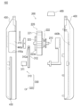
- FIG. 1 is an overall configuration diagram of a self-expanding stent delivery system according to a first embodiment.
- FIG. 2 is a cross-sectional view of the distal end portion of the self-expanding stent delivery system according to the first embodiment.
- FIG. 3 is a view for explaining the internal structure of the operation unit of the self-expanding stent delivery system according to the first embodiment.
- FIG. 4 is an exploded front view of the operation unit of the self-expanding stent delivery system according to the first embodiment.
- FIG. 5 is a diagram illustrating a state where the operation unit of the self-expanding stent delivery system according to the first embodiment is gripped.
- FIG. 1 is an overall configuration diagram of a self-expanding stent delivery system according to a first embodiment.
- FIG. 2 is a cross-sectional view of the distal end portion of the self-expanding stent delivery system according to the first embodiment.
- FIG. 3 is
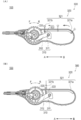
- FIG. 6 is a view for explaining an operation part of the self-expanding stent delivery system according to the first embodiment, and FIG. 6 (A) shows a state where the disengagement part is moved to the distal end side, FIG. 6B shows a state in which the engagement release portion applies a pressing force to the engagement portion.
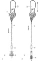
- 7A and 7B are diagrams showing a self-expanding stent delivery system according to a proportionality, in which FIG. 7A shows a state in which the pulling wire insertion tube is bent during pulling, and FIG. 7B shows a pulling wire. The self-expanding stent is released when the insertion tube is removed.
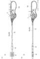
- FIG. 8 is a view showing the self-expanding stent delivery system according to the first embodiment, FIG.
- FIG. 8 (A) shows a state where the pulling wire insertion tube is bent at the time of towing
- FIG. 9 The state where the bending of the pulling wire insertion tube was eliminated by sending the pulling wire to the distal end side is shown.
- FIG. 9 is a view for explaining the operation part of the self-expanding stent delivery system according to the second embodiment
- FIG. 9 (A) shows a state where the disengagement part is moved to the distal end side
- FIG. 9B shows a state in which the engagement release portion applies a pressing force to the engagement portion.
- FIG. 10 is a view for explaining the operation part of the self-expanding stent delivery system according to the third embodiment
- FIG. 10 (A) shows a state where the disengagement part is moved to the distal end side
- FIG. 10B shows a state in which the engagement release portion applies a pressing force to the engagement portion.
- FIG. 11 is a view for explaining an operation unit of the self-expanding stent delivery system according to the fourth embodiment
- FIG. 11 (A) shows a state in which the lock unit is regulated
- FIG. ) Indicates a state in which the restriction by the lock portion is released.
- FIG. 1 is an overall configuration diagram of a self-expanding stent delivery system 10 (hereinafter referred to as “stent delivery system 10”) according to a first embodiment.
- FIG. 2 is a cross-sectional view of the distal end portion of the stent delivery system 10 according to the first embodiment.
- FIG. 3 is a view for explaining the internal structure of the operation unit 100 of the stent delivery system 10 according to the first embodiment.
- FIG. 4 is an exploded front view of the operation unit 100 of the stent delivery system 10 according to the first embodiment.
- FIG. 5 is a diagram illustrating a state where the operation unit 100 according to the first embodiment is gripped.
- FIG. 6 is a view for explaining the operation unit 100 according to the first embodiment.
- FIG. 6A shows a state in which the disengagement unit 320 is moved to the distal end side
- FIG. Indicates a state in which the engagement release unit 320 exerts a pressing force on the engagement unit 310.
- FIG. 7 is a view showing a self-expanding stent delivery system 10 ′ (hereinafter referred to as “stent delivery system 10 ′”) according to the proportionality.
- FIG. 7A shows a state where the pulling wire insertion tube 70 is pulled.
- FIG. 7B shows a state in which the self-expandable stent 30 (hereinafter referred to as “stent 30”) is released when the pulling wire insertion tube 70 is removed.
- FIG. 8 is a view showing the stent delivery system 10 according to the first embodiment.
- FIG. 8A shows a state in which the pulling wire insertion tube 70 is bent at the time of towing, and FIG. The state where the bending of the pulling wire insertion tube 70 is eliminated by feeding the wire to the distal end side
- the stent delivery system 10 includes an inner tube 20 through which a guide wire is inserted, a stent 30 disposed around the distal end side of the inner tube 20, and an outer surface of the inner tube 20.
- the outer tube 40 disposed on the side, the pulling wires 50a and 50b capable of pulling the outer tube 40 toward the proximal end, the distal end member 60 disposed on the leading edge, and the pulling wire through which the pulling wires 50a and 50b are inserted. It has the insertion tube 70 and the operation part 100 which operates the forward / backward movement of the pulling wires 50a and 50b.
- the side inserted into the body cavity is referred to as the distal end side (the direction of arrow A shown in the figure), and the side on which the operation unit 100 serving as the proximal side is provided is the proximal end side (arrow B shown in the figure).
- the proximal end side arrow B shown in the figure.
- the inner tube 20 is configured by a tubular body in which a guide wire lumen 20a penetrating from the distal end to the proximal end is formed.
- a guide wire (not shown) that guides the stent delivery system 10 to a lesion in a living body lumen is inserted into the guide wire lumen 20a.
- a tip member 60 is disposed at the forefront of the inner tube 20.
- the distal end member 60 is fixed to the distal end portion of the inner tube 20 by a stopper 22.
- the stopper 22 is embedded in the tip member 60 and prevents the tip member 60 from being detached.
- the stopper 22 is preferably formed of metal (for example, stainless steel).
- the distal end member 60 has a shape that gradually decreases in diameter toward the distal end, and is easily formed into a living body lumen.
- An opening 20 b is formed at the tip of the tip member 60.
- the tip member 60 may be constituted by a member separate from the inner tube 20 or may be constituted integrally by the same member as the inner tube 20.
- the base end side of the inner tube 20 is formed so as to be inclined obliquely toward the base end side, and is provided so as to be able to communicate with a guide wire outlet hole 43d of the outer tube 40 described later. . This facilitates guide wire guidance.
- the material for forming the inner tube 20 it is preferable to use a flexible material.
- a flexible material such as polyethylene and polypropylene, polyamides, polyamide elastomers, polyesters such as polyethylene terephthalate, polyester elastomers, fluorine-based polymers such as ETFE, PEEK, and polyimides can be used.
- a resin having thermoplasticity can be preferably used.
- a flexible material As the material for forming the tip member 60, it is preferable to use a flexible material.
- synthetic resin elastomers such as olefin elastomer, polyamide elastomer, styrene elastomer, polyurethane, urethane elastomer, fluororesin elastomer, synthetic rubber such as urethane rubber, silicone rubber, butadiene rubber, natural rubber such as latex rubber, etc. Rubbers are used.
- the stent 30 is a self-expanding stent. As shown by a one-dot chain line in FIG. 2, when inserted into the living body lumen, it is disposed in a stent accommodating portion 41 a described later in a state compressed inward in the radial direction around the long axis of the outer tube 40. When the outer tube 40 moves to the proximal end side, the stent 30 is exposed to the outside and released to the lesioned part in the living body lumen. This expands radially outward and restores the shape before compression.
- the stent 30 is formed in a substantially cylindrical shape with a mesh shape having a large number of openings.
- a superelastic alloy such as a Ni—Ti alloy can be suitably used.
- the pulling wires 50a and 50b are fixed to a first outer tube 41 and a second outer tube 42 provided in the outer tube 40 described later, respectively, and pull the outer tube 40 to the proximal end side.
- a material having relatively high rigidity For example, a metal such as Ni—Ti, brass, stainless steel, or aluminum, or a resin having relatively high rigidity, such as polyimide, vinyl chloride, or polycarbonate can be used.
- the pulling wire insertion tube 70 is formed in a tubular shape with a pulling wire lumen 70 a penetrating from the distal end to the proximal end.
- the pulling wires 50 a and 50 b are inserted through the pulling wire lumen 70 a and guided to the operation unit 100.
- the distal end portion of the pulling wire insertion tube 70 is disposed in the lumen of the outer tube 40 and is fixed to the proximal end portion of the inner tube 20.
- a proximal end portion of the pulling wire insertion tube 70 is fixed to the operation unit 100.
- the forming material of the pulling wire insertion tube 70 it is preferable to use a material having flexibility.
- a material having flexibility For example, polyolefins such as polyethylene and polypropylene, polyesters such as polyamide and polyethylene terephthalate, fluorine-based polymers such as ETFE, PEEK, and polyimide can be preferably used.
- the outer surface of the pulling wire insertion tube 70 may be coated with a resin having biocompatibility, particularly antithrombogenicity.
- the antithrombogenic material for example, polyhydroxyethyl methacrylate, a copolymer of hydroxyethyl methacrylate and styrene, or the like can be used.
- the outer tube 40 is disposed on the distal end side, and is disposed so as to be close to the first outer tube 41 that houses the stent 30 and the proximal end side of the first outer tube 41. And a third outer tube 43 disposed on the proximal end side of the second outer tube 42.
- the first outer tube 41 has a stent storage portion 41a that can be stored between the inner tube 20 and the stent 30 in a radially compressed state. As shown in FIG. 2, the outer surface of the inner tube 20 is in contact with the distal end side movement restricting portion 23 that abuts against the distal end side of the stent 30 and restricts the movement toward the distal end side, and the proximal end side of the stent 30. A proximal end movement restricting portion 24 that restricts movement toward the proximal end side is fixed.
- the distal end side and proximal end side movement restricting portions 23 and 24 are formed in an annular shape around the long axis of the outer tube 40.
- the stent housing portion 41 a is formed by a portion surrounded by the proximal end side movement restricting portion 24, the distal end side movement restricting portion 23, and the first outer tube 41.
- the first outer tube 41 is moved to the proximal side with respect to the inner tube 20.
- a frictional force acting on the stent 30 to move to the proximal end side with the movement of the first outer tube 41 acts.
- the movement of the stent 30 to the proximal end side is restricted by contacting the proximal end movement restricting portion 24.
- the distal end side movement restricting portion 23 has a tapered surface whose proximal end portion is reduced in diameter toward the proximal end side. For this reason, when the stent 30 is released, the distal-side movement restricting portion 23 does not become an obstacle, and the stent delivery system 10 can be easily recovered after the stent 30 is released.
- the first outer tube 41 is not fixed to the inner tube 20. For this reason, the first outer tube 41 is movable relative to the inner tube 20 in the major axis direction of the outer tube 40. Further, the first outer tube 41 has a fixing portion 41b to which end portions on the distal end side of the pulling wires 50a and 50b are fixed. The pulling wires 50a and 50b are fixed to the fixing portion 41b with an adhesive.
- an adhesive an epoxy resin, an ultraviolet curable resin, a cyanoacrylate resin, or the like can be suitably used.
- the outer surface of the first outer tube 41 is subjected to a treatment for exhibiting lubricity.
- a treatment for exhibiting lubricity examples include a method of coating or fixing a hydrophilic polymer such as polyhydroxyethyl methacrylate, polyhydroxyethyl acrylate, and polyvinylpyrrolidone.
- the above may be coated or fixed on the inner surface of the first outer tube 41 in order to improve the slidability of the stent 30.
- the first outer tube 41 may be formed of a combination of the two-layered polymers described above (for example, the outer surface is polyamide and the inner surface is PTFE).
- the material for forming the first outer tube 41 it is preferable to use a resin having flexibility, kink resistance, stretchability, and the like.
- a resin having flexibility, kink resistance, stretchability, and the like polyesters such as polyethylene, polypropylene, polyamide, and polyethylene terephthalate, fluorine polymers such as polyimide, PTFE, and ETFE, thermoplastic elastomers, and the like can be used.
- the first outer tube 41, the second outer tube 42, and the third outer tube 43 can be formed of the same material, but are not limited thereto, and are formed of different materials. May be.
- the second outer tube 42 is a ring-shaped member 42 c that fixes two distal end side tubular portions 42 a, reduced diameter portions 42 b, and pulling wires 50 a and 50 b, which are two tubular bodies having different outer diameters. And a main body portion 42d.
- the second outer tube 42 is movable to the proximal end side together with the first outer tube 41 by pulling the pulling wires 50a and 50b. Further, the second outer tube 42 is not fixed to the first outer tube 41.
- the diameter-reduced portion 42b for regulating the movement of the ring-shaped member 42c toward the distal end side is provided on the distal end side of the portion where the ring-shaped member 42c is disposed in the lumen of the second outer tube 42.
- the reduced diameter portion 42b restricts the movement of the ring-shaped member 42c toward the distal end side when the ring-shaped member 42c is abutted when the ring-shaped member 42c moves toward the distal end side.
- the ring-shaped member 42c Since the ring-shaped member 42c is arranged in a loosely fitted state with respect to the distal end side cylindrical portion 42a, the ring-shaped member 42c is configured to be rotatable in the circumferential direction of the outer tube 40 and movable in the major axis direction by the gap. ing.
- the pulling wires 50a and 50b are fixed to the ring-shaped member 42c with an adhesive.
- a material for forming the ring-shaped member 42c a material having relatively high rigidity is preferably used. For example, a metal, a resin, or the like can be used, and a metal can be particularly preferably used.
- the third outer tube 43 has a distal end side tube 43a having an inner diameter larger than the main body portion 42d of the second outer tube 42, and a proximal end fixed to the proximal end side of the distal end side tube 43a.
- Side tube 43b is
- the distal end side tube 43a is not fixed to the main body portion 42d, and is accommodated by sliding the main body portion 42d to the proximal end side.
- a second outer tube movement restricting portion 43c is provided on the proximal end side of the distal end side tube 43a. The second outer tube 42 can move to the proximal end side until it abuts on the second outer tube movement restricting portion 43c, but further movement toward the proximal end side is restricted.
- the distal tube 43a of the third outer tube 43 accommodates the main body portion 42d of the second outer tube 42.
- the present invention is not limited to this, and the inner diameter of the main body portion 42d is the distal tube.
- the main body 42d may be slid and accommodated in the distal end side tube 43a by a configuration larger than the outer diameter of 43a.
- the proximal end side tube 43b has a guide wire lead-out hole 43d that protrudes obliquely outward in the radial direction of the third outer tube 43 and opens.
- the guide wire lead-out hole 43 d is provided so as to be able to communicate with the guide wire lumen 20 a of the inner tube 20, and the guide wire can be led out of the outer tube 40.
- a puller wire insertion tube 70 is fixed in the lumen of the proximal tube 43b.
- the operation unit 100 is fixed to the proximal end of a pulling wire insertion tube 70 through which the pulling wires 50a and 50b are inserted.
- the operation unit 100 includes a holding unit 200 that holds the pulling wires 50 a and 50 b in a state in which the pulling wires 50 a and 50 b can move to the distal end side and the proximal end side, and the pulling wires 50 a and 50 b held by the holding unit 200.
- It has the switching part 300 which can switch the restriction
- the holding unit 200 is configured to be rotatable about the rotating shaft 210 supported at both ends by the housing unit 400 and the rotating shaft 210, and the pulling wire 50 a is accompanied with the rotation. , 50b, and a rotating member 220 that performs winding and feeding.
- the rotary shaft 210 is provided so as to be substantially orthogonal to the advancing / retreating direction of the pulling wires 50a, 50b.
- the rotating shaft 210 is not particularly limited, but may include a rolling bearing such as a ball bearing or a roller bearing, a sliding bearing including a working fluid using oil, air, or the like.
- a rolling bearing such as a ball bearing or a roller bearing
- a sliding bearing including a working fluid using oil, air, or the like.
- metals such as carbon alloy steel and stainless steel, resins, and the like can be used.
- the rotating member 220 rotates around the rotating shaft 210 and has a disk-shaped rotating roller 221 having an uneven shape on the outer surface around the circumference. Similarly, the rotating member 220 rotates around the rotating shaft 210 and pulls the wires 50a and 50b. A disk-shaped take-up shaft portion 222 that winds and feeds out, and a gear portion 223 capable of restricting the rotational operation of the rotating roller 221 and releasing the restriction.
- Rotating roller 221 has a portion that protrudes outward from housing portion 400.
- the side having the protruding portion of the rotating roller 221 is referred to as the upper side of the operation unit 100, and the opposite side is referred to as the lower side.
- the user moves the protruding portion clockwise in the direction of the arrow R (direction in which the pulling wires 50a and 50b are wound), or counterclockwise in the direction of the arrow F (by pulling the pulling wires 50a and 50b).
- the rotation roller 221 can be rotated around the rotation shaft 210 by performing the rotation operation.
- Rotating roller 221 has an uneven shape on the outer surface around the circumference. Since the surface of the surface that the user (operator) may come into contact with when operating the rotating roller 221 has a concavo-convex shape, it plays a role as an anti-slip function, thereby facilitating the rotation operation.
- the concavo-convex shape is formed by, for example, a plurality of protrusions arranged on the outer surface around the circumference of the traction wires 50a and 50b at substantially equal intervals along the forward / backward movement direction.
- the anti-slip function is not limited to the concavo-convex shape, and surface treatment such as knurling, embossing, and high friction material coating may be applied to the outer surface around the circumference of the rotating roller 221.
- the winding shaft portion 222 has a cylindrical shape, and the proximal end portions of the pulling wires 50a and 50b are held or fixed to the outer surface around the circumference of the winding shaft portion 222.
- the winding shaft portion 222 is formed integrally with the rotating roller 221 on one side surface of the rotating roller 221, and rotates around the rotating shaft 210 when the rotating roller 221 rotates.
- the proximal end portions of the pulling wires 50a and 50b gripped or fixed to the outer surface on the circumference are pulled, and the pulling wires 50a and 50b are It is wound around the outer surface of the winding shaft portion 222 and moves to the proximal end side.
- a repulsive force is applied to the side opposite to the pulling direction (base end side) (tip end side) as a reaction of the pulling force by pulling.
- the take-up shaft portion 222 rotates counterclockwise along the arrow F direction by this repulsive force, the pulling wires 50a and 50b rewind from the take-up shaft portion 222 and move to the tip side.
- the gear portion 223 has a disk shape, and is coaxially and integrally formed around the rotating shaft 210 on the side surface of the rotating roller 221 opposite to the side where the winding shaft portion 222 is provided.
- the outer diameter of the gear portion 223 is smaller than the outer diameter of the rotating roller 221, and the surface of the gear portion 223 on the winding shaft portion 222 side is formed integrally with the rotating roller 221.
- On the outer surface around the circumference of the gear portion 223, a plurality of meshing teeth 223a are formed at substantially equal intervals along the entire circumference along the advancing / retreating movement direction of the pulling wires 50a, 50b.
- the meshing teeth 223a have a shape inclined in the direction of arrow F with respect to the radial direction.
- the gear portion 223 rotates counterclockwise along the arrow F direction when engaging with the engagement portion 310 described later, the gear portion 223 does not move in the arrow R direction. It is configured to be disengaged and rotatable when it rotates clockwise along the axis.
- the rotating roller 221, the winding shaft portion 222, and the gear portion 223 are integrally formed.
- the present invention is not limited to this, and the rotating roller 221 rotates to follow and rotate. It may be constituted by another member that moves.
- a transmission method of the rotation of the rotating roller 221 for example, a gear type, a belt type, or the like can be used, but is not limited thereto.
- the switching unit 300 includes an engaging unit 310 that restricts the rotation of the rotating member 220 by engaging with the rotating member 220, and an engagement between the rotating member 220 and the engaging unit 310. And an engagement release unit 320 that releases the restriction by the switching unit 300 by releasing the connection.
- the engaging portion 310 includes a fixed shaft 311 fixed to the housing portion 400 and a reverse return preventing member 312 that rotates around the fixed shaft 311.
- the reverse return preventing member 312 is provided so as to face the meshing teeth 223a of the gear portion 223, and has a concave meshing portion 312a provided so that the meshing teeth 223a are inserted and engageable.
- the reverse prevention member 312 is formed of an elastically deformable material, and is deformed in a direction for separating the meshing portion 312a from the meshing tooth 223a of the gear portion 223 by an engagement releasing portion 320 described later, so that the engagement can be released. It is configured.
- the reverse prevention member 312 is formed of an elastically deformable material, it is not limited thereto, and may be formed to be elastically deformable by having an elastic member such as a spring.
- a spring may be provided on the fixed shaft 311 so that the reverse return preventing member 312 can be elastically rotated around the fixed shaft 311.
- the meshing portion 312a When the meshing portion 312a is engaged with one meshing tooth 223a of the gear portion 223, the meshing portion 312a has a concave shape inclined in the arrow F direction with respect to the radial direction of the gear portion 223. Therefore, as described above, the engagement is not disengaged even when the gear portion 223 is rotated in the direction of the arrow F, but the engagement is disengaged when the gear portion 223 is rotated in the clockwise direction along the direction of the arrow R. It can be rotated.
- the rotation of the rotating member 220 in the feed-out direction is restricted, but the rotation of the rotating member 220 in the winding direction of the pulling wires 50a and 50b is limited.
- the movement is not limited and is configured to be rotatable. The movement of the pulling wires 50a and 50b toward the distal end side can be suitably limited by the engagement between the rotating member 220 and the engaging portion 310.
- the disengagement part 320 can move toward and away from the slide part 321 provided in the housing part 400 so as to be able to advance and retreat along the advancing and retreating movement direction of the pulling wires 50a and 50b.
- a pressing member 322 that applies a pressing force in a direction to move the engaging portion 310 away from the rotating member 220 as the slide member 321 moves forward and backward.
- the slide member 321 has a rail-shaped guide member 321a and a movable member 321b that can slide and move on the guide member 321a.
- the guide member 321a extends from the upper base end portion of the housing portion 400 along the shape of the upper surface of the housing portion 400 in the advancing and retreating movement direction of the pulling wires 50a and 50b, and further extends downward to the vicinity of the upper side of the back prevention member 312.
- the movable member 321b is configured to be movable back and forth from the upper base end portion of the housing portion 400 to the vicinity of the upper side of the reverse return preventing member 312 along the forward and backward movement direction of the pulling wires 50a and 50b.
- the guide member 321a can be configured by a separate member from the accommodating portion 400, or may be integrally configured by the same member as the accommodating portion 400.
- the movable member 321b has a portion that protrudes outward from the housing portion 400.
- the pulling wires 50a and 50b can move in the advancing and retracting directions. Further, after moving to the distal end side along the guide member 321a and further moving to the vicinity of the upper side of the reverse return preventing member 312 in the downward direction, it can be returned to the proximal end side before the movement again.
- the pressing member 322 is provided at the end opposite to the protruding portion of the movable member 321b, and is configured to move closer to and press against the reversion preventing member 312 as the movable member 321b moves forward and backward.
- the reverse prevention member 312 By pressing the reverse prevention member 312, the reverse prevention member 312 can be deformed.
- the meshing tooth 223a of the rotating member 220 and the meshing part 312a of the engaging part 310 can be moved relatively apart to disengage the meshing tooth 223a from the meshing part 312a.
- the movable member 321b can be moved to the vicinity of the upper side of the reverse preventing member 312 along the guide member 321a, the distance between the portion that presses the movable member 321b and the reverse preventing member 312 is shortened. Therefore, it is possible to reduce the pressing force required for deforming the reverse prevention member 312.
- the pressing member 322 may include a spring-like member having flexibility for alleviating an impact when the reverse return preventing member 312 is pushed in. Further, since the reverse prevention member 312 can be elastically deformed, when the pressing force by the pressing member 322 is removed, the retraction preventing member 312 is engaged with the rotating member 220 again to limit the movement of the pulling wires 50a and 50b toward the tip side. Therefore, you may have a stopper (not shown) which maintains the state which the press member 322 pressed the reverse prevention member 312. FIG.
- the accommodating portion 400 has a shape in which the proximal end side and the central portion are bent and rounded, and accommodates the holding portion 200 and the switching portion 300.
- the accommodating part 400 includes a first opening part 410 opened on the upper surface, a finger hooking part 420 that can be hooked with fingers when operating the pulling wires 50a and 50b via the holding part 200, and an engagement releasing part 320 It has the 2nd opening part 430 which exposes a part, bearing part 440a, 440b, and the connection member 450.
- the first opening portion 410 is an opening provided on the upper surface of the housing portion 400 and exposes a part of the rotating roller 221 of the holding portion 200 to the outside of the housing portion 400. Since the rotation roller 221 can be operated from the outside of the housing part 400, the operation becomes easy.
- the opening edge portion 410a and the rotating roller 221 are configured to be separated from each other so as not to interfere with each other, and the housing portion 400 is configured not to interfere with the rotating operation even when the rotating roller 221 is rotated.
- the finger rest 420 is formed on the lower surface of the housing 400 and has a plurality of curved portions.
- the size of the curved portion is formed so as to follow the curved surface of the finger on the palm side of the human hand.
- the finger hooking portion 420 can be put on with fingers when the user (operator) holds the housing portion 400, and can stably hold the housing portion 400.
- the number of curved portions is preferably four or more so that all fingers other than the thumb can be hung, but is not limited thereto.
- the second opening 430 is formed at a position spaced from the extension line L (broken line in FIG. 3) connecting the first opening 410 and the finger-hooking part 420 to the base end side, and is one of the movable members 321b of the disengaging part 320.
- the part is exposed to the outside of the housing part 400. Since the movable member 321b can be operated from the outside of the accommodating part 400, operation becomes easy.
- the second opening 430 is formed with an opening from the upper base end portion of the housing portion 400 to the upper side of the reverse-preventing member 312 closer to the base end side than the first opening 410. Thereby, as shown in FIG.
- the protruding part of the movable member 321b of the disengaging part 320 can be arranged at the upper base end part of the accommodating part 400 which is a position where the hand does not touch during operation,
- the restriction on the rotation of the rotating member 220 by the switching unit 300 is not canceled by mistake during operation.
- the restriction can be released by moving the movable member 321b of the disengagement part 320 to the vicinity of the upper side of the reverse prevention member 312 and pressing the reverse prevention member 312. .
- the two bearing portions 440 a and 440 b accommodate one end on the gear portion 223 side of the rotating shaft 210 and the other end of the rotating shaft 210 on the winding shaft portion 222 side, respectively.
- the rotating member 220 is accommodated in the accommodating part 400 so that both ends can be supported.
- the connecting member 450 includes a connector 451 connected to the pulling wire insertion tube 70 and a seal member 452.
- the distal end portion of the connector 451 is fixed to the proximal end portion of the pulling wire insertion tube 70.
- the seal member 452 is connected to the proximal end portion of the connector 451.
- the engagement release portion 320 is arranged at the upper base end portion of the housing portion 400 before the restriction on the movement of the pulling wires 50 a and 50 b to the distal end side is released.
- the rotating member 220 rotates in the feeding direction (arrow F direction) of the rotating member 220. And the movement of the pulling wires 50a and 50b held by the holding unit 200 toward the distal end side is restricted.
- the movable member 321b of the disengagement part 320 is advanced from the upper base end part of the housing part 400 along the advancing and retreating direction of the pulling wires 50a and 50b. It is moved to the upper side of the reverse return preventing member 312 on the side.
- the guide member 321a is pushed downward, and the reverse return preventing member 312 is pushed downward. Due to the pressing force, the reverse return preventing member 312 is deformed downward, and the engagement is released by moving the engaging part 310 away from the gear part 223 of the rotating member 220.
- the rotating member 220 can rotate in the delivery direction (arrow F direction), so that the restriction on the movement of the pulling wires 50a and 50b to the distal end side is released and the rotating member 220 can move. Accordingly, the movement of the members relative to each other can be released by the operation of moving the members relatively apart from each other, so that the restriction of the movement of the pulling wires 50a and 50b toward the distal end side can be released. Moreover, the restriction
- the stent delivery system 10 'according to the comparative example includes the engagement portion 310 that restricts the movement of the pulling wires 50a and 50b toward the distal end side, but does not include the engagement release portion 320 that releases the restriction. .
- the traction wire insertion tube 70 that inserts the traction wires 50a and 50b closer to the proximal end than the outer tube 40 is bent by an amount corresponding to a reduction in the distance between the outer tube 40 and the operation unit 100 '.
- the outer tube 40 is suddenly released from the restraining force by the narrowed portion.
- a force in a direction in which the stent 30 is released to the distal end side of the outer tube 40 acts on the stent 30 as shown in FIG. 7B due to the restoring force to return the bending of the pulling wire insertion tube 70 to the original state.
- the stent 30 may be released at an unintended timing.
- the user is forced to remove the distal end portion of the stent delivery system 10 ′ while paying attention to prevent the release of the stent 30. Therefore, the procedure time is increased. There is a case to be.
- the stent delivery system 10 shown in FIG. 8 inserts the outer tube 40 in the radial direction in the stenosis portion when the distal end portion is inserted into the stenosis portion (lesion portion).
- the pulling wire insertion tube 70 on the proximal end side from the outer tube 40 may be bent due to a binding force that pushes the tube toward the outside.
- FIG. 8 (A) the stent delivery system 10 shown in FIG. 8 inserts the outer tube 40 in the radial direction in the stenosis portion when the distal end portion is inserted into the stenosis portion (lesion portion).
- the pulling wire insertion tube 70 on the proximal end side from the outer tube 40 may be bent due to a binding force that pushes the
- the bending state of the pulling wire insertion tube 70 can be eliminated by returning to the state before pulling. Since the tip side portion can be removed from this state, it can be easily removed and the operability is improved.
- the operation unit 100 of the stent delivery system 10 includes the holding unit 200 that holds the pulling wires 50a and 50b in a movable state toward the distal end side and the proximal end side, and the holding unit 200. And a switching unit 300 that can switch the restriction of the movement of the pulling wires 50a and 50b to the tip side and the release of the restriction.
- the pulling wires 50a and 50b are not only pulled and moved to the proximal end side, but also after being once moved to the proximal end side, the pulling wires 50a and 50b are moved to the distal end. Can be moved again to the side. Therefore, the operability can be further improved. Further, it is preferable that the stent 30 is released at an unintended timing even when a restraining force that presses the outer tube 40 radially inward is applied to a stenosis or the like existing in the living body lumen. Therefore, convenience during use is improved.
- the holding unit 200 is configured to be rotatable, and includes a rotating member 220 that winds and sends the pulling wires 50 a and 50 b along with the rotation, and the switching unit 300 engages with the rotating member 220.
- the engaging portion 310 that restricts the rotation of the rotating member 220 and the engagement releasing portion 320 that releases the restriction by the switching portion 300 by releasing the engagement between the rotating member 220 and the engaging portion 310 are provided. .
- the movement of the pulling wires 50a and 50b toward the distal end side can be suitably limited by the engagement between the rotating member 220 and the engaging portion 310. Further, when it is desired to release the restriction, it can be easily released by releasing the engagement.
- the engagement release unit 320 is configured to be able to release the engagement with the relative separation movement of the rotating member 220 and the engagement unit 310.
- the disengagement unit 320 can release the restriction of the movement of the pulling wires 50a and 50b toward the distal end side by an operation of moving the members relatively apart from each other. Because it can, it can be easily operated.
- the disengagement part 320 can move toward and away from the slide part 321 provided in the housing part 400 so as to be able to advance and retreat along the advancing and retreating movement direction of the pulling wires 50a and 50b. And a pressing force that moves toward and away from the engaging portion 310 as the slide member 321 advances and retreats, and applies a pressing force in a direction that separates the reversal prevention member 312 (engaging portion 310) from the rotating member 220. And a member 322.
- the restriction of the movement of the pulling wires 50a and 50b toward the distal end side can be released more quickly by an easy operation of pressing the reverse return preventing member 312.
- the slide member 321 includes a rail-shaped guide member 321a and a movable member 321b that can move by sliding on the guide member 321a, and a pressing member 322 is provided at an end of the movable member 321b. .
- the movable member 321b can be moved to the vicinity of the upper side of the reverse prevention member 312 along the guide member 321a.
- the distance to the member 312 is shortened. Therefore, it is possible to reduce the pressing force required for deforming the reverse prevention member 312.
- the storage unit 400 includes a first opening 410 that exposes a part of the holding unit 200 to the outside, and a finger-hanging unit that can be hooked with fingers when operating the pulling wires 50a and 50b via the holding unit 200. 420, and a second opening 430 that exposes a part of the disengagement part 320 at a position spaced from the extension line L connecting the first opening 410 and the finger hooking part 420 to the base end side.
- the disengagement unit 320 can be disposed at a position where the hand does not touch during operation, and the rotation member 220 is erroneously rotated by the switching unit 300 during operation. The restriction will not be lifted.
- FIG. 9 is a view for explaining an operation unit 100a of a self-expanding stent delivery system 10a (hereinafter referred to as “stent delivery system 10a”) according to the second embodiment.
- FIG. 9B shows a state in which the engagement release portion 520 is moved to the distal end side
- FIG. 9B shows a state in which the engagement release portion 520 exerts a pressing force on the engagement portion 310.
- the stent delivery system 10a according to the second embodiment will be described with reference to FIG.
- the stent delivery system 10a according to the second embodiment differs from the first embodiment only in the configuration of the disengagement unit 520 of the operation unit 100a, and the other configurations are the same as those in the first embodiment.
- description of the same configuration as that of the first embodiment will be omitted.
- the member which has the structure similar to 1st Embodiment it demonstrates using the same code
- the disengagement unit 520 includes a slide member 521 provided in the housing unit 400 so as to be movable forward and backward along the forward and backward movement directions of the pulling wires 50 a and 50 b. , Provided so as to be able to move toward and away from the engaging portion 310, and move toward the engaging portion 310 as the slide member 521 moves forward and backward to move the engaging portion 310 away from the rotating member 220. And a pressing member 522 for applying a pressing force.
- the slide member 521 has a rod-like portion that extends from the upper base end portion of the housing portion 400 to the upper side of the reverse return preventing member 312 along the forward / backward movement direction of the pulling wires 50 a and 50 b, and the base end portion is the pressing member 522. It is comprised so that it may contact
- the pressing member 522 is provided in the vicinity of the upper side of the reverse return preventing member 312. Due to the movement of the slide member 521 toward the distal end side, the upper side of the pressing member 522 comes into contact with the distal end side of the slide member 521.
- the front end side of the slide member 521 and the upper side of the pressing member 522 are formed to be slidable with each other, and the pressing member 522 is configured to be movable downward by this sliding movement. By pressing the slide member 521, the pressing member 522 moves closer to the reverse return preventing member 312 and presses it.
- the slide member 521 is disposed at a position on the proximal end side that does not come into contact with the pressing member 522 before the restriction of the movement of the pulling wires 50a and 50b to the distal end side is released.
- the reverse return preventing member 312 of the engaging portion 310 is engaged with the engaging portion 310 of the rotating member 220, the rotating member 220 rotates in the feeding direction (arrow F direction) of the rotating member 220. And the movement of the pulling wires 50a and 50b held by the holding unit 200 toward the distal end side is restricted.
- the portion protruding from the housing portion 400 of the slide member 521 is pushed into the tip side.
- the front end side of the slide member 521 and the upper side of the pressing member 522 come into contact with each other, the pressing member 522 moves downward, and the pressing member 522 presses the reverse return preventing member 312. Due to the pressing force, the reverse return preventing member 312 is deformed downward, and the engagement is released by moving the engaging part 310 away from the gear part 223 of the rotating member 220.
- the rotating member 220 can rotate in the delivery direction (arrow F direction), so that the restriction on the movement of the pulling wires 50a and 50b to the distal end side is released and the rotating member 220 can move.
- the operation unit 100a of the stent delivery system 10a includes the storage unit 400 that stores the holding unit 200 and the switching unit 500, as in the first embodiment.
- the disengagement portion 520 can move toward and away from the engagement portion 310 and the slide member 521 provided in the housing portion 400 so as to be able to advance and retract along the advancing and retreating movement direction of the pulling wires 50a and 50b.
- a pressing force that applies a pressing force in a direction to move the retraction preventing member 312 (engaging portion 310) away from the rotating member 220 by moving closer to the engaging portion 310 as the slide member 521 moves back and forth.
- Member 522 is provided to the storage unit 400 that stores the holding unit 200 and the switching unit 500, as in the first embodiment.
- the restriction on the movement of the pulling wires 50a and 50b to the distal end side can be released by a simple operation of pressing the reverse return preventing member 312. Since it can be easily released, the operability can be further improved.
- the distal end side of the slide member 521 and the upper side of the pressing member 522 are in contact with each other so as to be slidable, and the pressing member 522 is configured to be movable downward by this sliding movement.
- the restriction of the movement of the pulling wires 50a and 50b toward the distal end side can be released by one operation of pushing the slide member 521, so that the releasing operation can be performed in a short time. It can be carried out.
- FIG. 10 is a view for explaining an operation unit 100b of a self-expanding stent delivery system 10b (hereinafter referred to as “stent delivery system 10b”) according to the third embodiment.
- FIG. FIG. 10B shows a state in which the engagement release unit 620 is moved to the distal end side
- FIG. 10B shows a state in which the engagement release unit 620 exerts a pressing force on the engagement unit 310.
- the stent delivery system 10b according to the third embodiment will be described with reference to FIG.
- the stent delivery system 10b according to the third embodiment is different from the first embodiment only in the configuration of the holding unit 200, the disengagement unit 620, and the bearing unit of the operation unit 100b, and other configurations are the same as those of the first embodiment. is there.
- description of the same configuration as that of the first embodiment will be omitted.
- the member which has the same structure as 1st Embodiment it demonstrates using the same code
- the holding unit 200 is configured to have a rotating shaft 210 supported at both ends by the housing unit 400, and to be rotatable about the rotating shaft 210 and movable in the direction of the rotating shaft 210. And a rotating member 220 that winds and feeds the pulling wires 50a and 50b.
- the configuration of each component of the rotating member 220 is the same as that of the first embodiment.
- the rotating member 220 according to the third embodiment is different from the first embodiment in that it is configured to be movable in the direction of the rotating shaft 210.
- the moving direction in the direction of the rotating shaft 210 is not particularly limited, but in the present embodiment, the constituent members are configured to move integrally with the rotating roller 221 toward the winding shaft portion 222.
- the structure of the rotating shaft 210 is not particularly limited, and includes, for example, a first rotating shaft 210a disposed on the gear portion 223 side and a second rotating shaft 210b disposed on the winding shaft portion 222 side. It can be configured.
- the first rotating shaft 210a and the second rotating shaft 210b have a nesting structure that can slide with respect to each other.
- the rotating member 220 is integrally assembled on the outer periphery of the first rotating shaft 210a, and is configured to retreat in the axial direction as the first rotating shaft 210a moves in the axial direction. Yes.
- the second rotating shaft 210b slides and is accommodated in the first rotating shaft 210a as the first rotating shaft 210a moves in the axial direction. With the above configuration, the rotating shaft 210 can be expanded and contracted in the axial direction.
- the bearing portion that supports the rotating shaft 210 is provided with only the bearing portion 440b on the take-up shaft portion 222 side with respect to the rotating roller 221, and an insertion hole 460 through which the rotating shaft 210 is inserted is formed on the other side.
- the disengagement unit 620 disengages with the relative separation movement of the rotation member 220 and the engagement unit 310 in the direction of the rotation axis 210. It has a possible pressing member 622.
- the pressing member 622 is provided coaxially with the rotating shaft 210 of the rotating member 220.
- the pressing member 622 is fixed to one end portion of the rotating shaft 210 inserted through the insertion hole 460.
- the rotating shaft 210 is pushed into the housing part 400 from the side surface side where the pressing member 622 is provided. Thereby, the rotating shaft 210 contracts.
- the other end portion of the rotating shaft 210 is not moved in the axial direction by the bearing portion of the housing portion 400.
- the rotating member 220 is configured to be movable in the direction of the rotating shaft 210.
- the engagement portion 310 is arranged on the rotation surface of the gear portion 223 before the restriction of the movement of the pulling wires 50a and 50b to the tip side is released.
- the rotating member 220 rotates in the feeding direction (arrow F direction) of the rotating member 220. And the movement of the pulling wires 50a and 50b held by the holding unit 200 toward the distal end side is restricted.
- the pressing member 622 When it is desired to release the restriction, as shown in FIG. 10B, the pressing member 622 is pushed in from the side surface side where the pressing member 622 is provided to the other side surface side.
- the rotating shaft 210 contracts due to the pressing force of the pressing member 622. With this contraction, the rotating member 220 moves to the other side surface.
- the engagement is released by moving the gear portion 223 away from the engaging portion 310 of the rotating member 220 in the direction of the rotating shaft 210. In this state, the rotating member 220 can rotate in the delivery direction (arrow F direction), so that the restriction on the movement of the pulling wires 50a and 50b to the distal end side is released and the rotating member 220 can move.
- the disengagement part 620 of the stent delivery system 10b is used to move the gear part 223 of the rotation member 220 and the engagement part 310 away from each other in the direction of the rotation axis 210. Accordingly, the engagement can be released.
- the release since the rotation surface of the gear portion 223 and the operation region of the engaging portion 310 do not overlap, the release may be erroneously released due to elastic deformation or the like of the reverse prevention member 312. Absent. Therefore, the operability can be further improved.
- FIG. 11A is a view for explaining an operation unit 100c of a self-expanding stent delivery system 10c (hereinafter referred to as “stent delivery system 10c”) according to a fourth embodiment, and FIG. FIG. 11B shows a state in which the restriction by the lock unit 730 is released.
- stent delivery system 10c according to the fourth embodiment will be described with reference to FIG.
- the stent delivery system 10c according to the fourth embodiment is different from the first embodiment only in the configuration of the disengagement unit 720 and the lock unit 730, and other configurations are the same as those in the first embodiment. Hereinafter, description of the same configuration as that of the first embodiment will be omitted. In addition, about the member which has the structure similar to 1st Embodiment, it demonstrates using the same code
- the stent delivery system 10c further includes a lock unit 730 capable of switching between the restriction of the release operation that the switching unit 700 releases the restriction and the release of the restriction.
- the lock part 730 is provided on the upper side of the housing part 400 so as to be slidable.
- the lock portion 730 further includes a locking member 730 a that is locked to the pressing member 722.
- the disengagement part 720 has a pressing member 722 that can be disengaged with the relative separation movement of the rotation member 220 and the engagement part 310 in the direction of the rotation axis 210.
- the pressing member 722 is arranged on the upper side of the reverse return preventing member 312 before the restriction of the movement of the pulling wires 50a and 50b to the tip side is released.
- the lock portion 730 locks the pressing member 722 by the locking member 730 a
- the downward movement of the pressing member 722 pressing against the reverse return preventing member 312 is restricted.
- the reverse return preventing member 312 of the engaging portion 310 is engaged with the engaging portion 310 of the rotating member 220, the rotating member 220 rotates in the feeding direction (arrow F direction) of the rotating member 220. And the movement of the pulling wires 50a and 50b held by the holding unit 200 toward the distal end side is restricted.
- the locking member 730a is moved away from the pressing member 722 by moving the locking portion 730 to the proximal end side to release the locking to release the locking portion.
- the restriction by 730 is released.
- the pressing member 722 is pushed downward.
- the pressing member 722 moves downward, and the pressing member 722 presses the reverse return preventing member 312. Due to the pressing force, the reverse return preventing member 312 is deformed downward, and the engagement is released by moving the engaging part 310 away from the gear part 223 of the rotating member 220.
- the rotating member 220 can rotate in the delivery direction (arrow F direction), so that the restriction on the movement of the pulling wires 50a and 50b to the distal end side is released and the rotating member 220 can move. Accordingly, the release operation for releasing the restriction by the switching unit 700 cannot be performed unless the lock unit 730 is released. Therefore, regardless of the disposition of the disengagement unit 720 of the switching unit 700, the restriction on the rotation of the rotating member 220 by the switching unit 700 is not erroneously canceled during operation, so that the operability can be further improved. .
- the stent delivery system 10c further includes the lock unit 730 that can switch between the restriction of the release operation that the switching unit 700 releases the restriction and the release of the restriction.
- the stent delivery system 10c configured in this way, regardless of the disposition of the disengagement unit 720 of the switching unit 700, the restriction on the rotation of the rotating member 220 by the switching unit 700 is not canceled by mistake during operation. Therefore, the operability can be further improved.
- the stent delivery systems 10, 10a, 10b, and 10c have been described through the embodiments.
- the present invention is not limited to the configurations described in the embodiments, and may be appropriately changed based on the description of the claims. It is possible.
- the rotating member 220 rotates clockwise along the arrow R direction
- the pulling wires 50a and 50b are wound and rotated counterclockwise along the arrow F direction
- the pulling wires 50a and 50b are sent out.
- the present invention is not limited to this.
- the pulling wires 50a and 50b are rotated in the direction of arrow F
- the pulling wires 50a and 50b are wound up and rotated in the clockwise direction along the arrow R.
- the wires 50a and 50b may be sent out.
- the holding part 200 has a gear part 223, and the movement of the pulling wires 50a and 50b to the distal end side is restricted by the engagement of the gear part 223 and the engaging part 310, but this is limited to this. It is not a thing.
- the take-up shaft portion 222 may have a meshing tooth 223a and engage with the engaging portion 310.
- the pressing member 322 is configured to be able to return to the state before being pressed after being pressed once against the engaging portion 310. It is not limited to this, The structure which cannot cancel
- rock part 730 demonstrated as 4th Embodiment is not limited to the said embodiment,
- the pressing member 322 presses the reverse return preventing member 312 downward to release the engagement, but the pressing direction is limited to this. It may press from any direction.
- the outer tube 40 includes the first outer tube 41, the second outer tube 42, and the third outer tube 43.
- the outer tube 40 is not limited to this.
- Stent delivery system self-expanding stent delivery system
- 20 inner pipe 30 stent (self-expanding stent), 40 outer pipe, 50a, 50b puller wire, 60 tip member, 70 puller wire insertion tube, 100, 100 ′, 100a, 100b, 100c operation unit, 200 holder, 210 rotation axis, 220 rotating member, 221 rotating roller, 222 winding shaft, 223 gear part, 223a meshing teeth, 300, 500, 600, 700 switching unit, 310 engaging portion, 311 fixed shaft, 312 an anti-reverse member, 312a meshing part, 320, 520, 620, 720 disengagement part, 321, 521 slide member, 321a guide member, 321b movable member, 322, 522, 622, 722 pressing member, 730 lock part, 400 containment section, 410 first opening, 420 finger rest, 430 second opening, L Extension line.
Landscapes
- Health & Medical Sciences (AREA)
- Engineering & Computer Science (AREA)
- Biomedical Technology (AREA)
- Cardiology (AREA)
- Oral & Maxillofacial Surgery (AREA)
- Transplantation (AREA)
- Heart & Thoracic Surgery (AREA)
- Vascular Medicine (AREA)
- Life Sciences & Earth Sciences (AREA)
- Animal Behavior & Ethology (AREA)
- General Health & Medical Sciences (AREA)
- Public Health (AREA)
- Veterinary Medicine (AREA)
- Media Introduction/Drainage Providing Device (AREA)
Abstract
Le problème de l'invention concerne un système autoexpensible de pose d'endoprothèse conçu de telle sorte que des fils de traction peuvent être déplacés vers le côté d'extrémité distale et le côté d'extrémité proximale, ce qui permet d'améliorer davantage la facilité de fonctionnement du système autoexpansible de pose d'endoprothèse. Selon la solution de l'invention, une section de fonctionnement 100 présente : une section de maintien 200 permettant de tenir des fils de traction 50a, 50b de telle sorte que les fils de traction 50a, 50b peuvent être déplacés vers le côté d'extrémité distale et le côté d'extrémité proximale ; et une section de commutation 300 pouvant commuter entre un état dans lequel le mouvement des fils de traction 50a, 50b tenus par la section de maintien vers le côté d'extrémité distale est limité et un état dans lequel la limitation est supprimée.
Priority Applications (4)
| Application Number | Priority Date | Filing Date | Title |
|---|---|---|---|
| EP16761429.6A EP3269337A4 (fr) | 2015-03-11 | 2016-02-12 | Système autoexpansible de pose d'endoprothèse |
| JP2017504935A JP6612847B2 (ja) | 2015-03-11 | 2016-02-12 | 自己拡張型ステントデリバリーシステム |
| CN201680014355.3A CN107427379A (zh) | 2015-03-11 | 2016-02-12 | 自扩张型支架输送系统 |
| US15/698,943 US20170367862A1 (en) | 2015-03-11 | 2017-09-08 | Self-expandable stent delivery system |
Applications Claiming Priority (2)
| Application Number | Priority Date | Filing Date | Title |
|---|---|---|---|
| JP2015048759 | 2015-03-11 | ||
| JP2015-048759 | 2015-03-11 |
Related Child Applications (1)
| Application Number | Title | Priority Date | Filing Date |
|---|---|---|---|
| US15/698,943 Continuation US20170367862A1 (en) | 2015-03-11 | 2017-09-08 | Self-expandable stent delivery system |
Publications (1)
| Publication Number | Publication Date |
|---|---|
| WO2016143457A1 true WO2016143457A1 (fr) | 2016-09-15 |
Family
ID=56879447
Family Applications (1)
| Application Number | Title | Priority Date | Filing Date |
|---|---|---|---|
| PCT/JP2016/054155 Ceased WO2016143457A1 (fr) | 2015-03-11 | 2016-02-12 | Système autoexpansible de pose d'endoprothèse |
Country Status (5)
| Country | Link |
|---|---|
| US (1) | US20170367862A1 (fr) |
| EP (1) | EP3269337A4 (fr) |
| JP (1) | JP6612847B2 (fr) |
| CN (1) | CN107427379A (fr) |
| WO (1) | WO2016143457A1 (fr) |
Cited By (4)
| Publication number | Priority date | Publication date | Assignee | Title |
|---|---|---|---|---|
| KR20190091479A (ko) * | 2016-12-30 | 2019-08-06 | 세븐 썬즈 리미티드 알.엔. 515985570 (더 "컴퍼니") | 관상 동맥 내에서 관상 동맥 스텐트를 안전하게 포지셔닝하기 위한 디바이스 및 방법 |
| JP2021525556A (ja) * | 2018-05-30 | 2021-09-27 | ヴェスパー メディカル、 インコーポレイテッドVesper Medical, Inc. | 回転ハンドル・ステント・デリバリー・システムおよび方法 |
| CN114786629A (zh) * | 2019-11-19 | 2022-07-22 | 真复灵公司 | 用于植入物在前列腺尿道中的准确展开和成像的系统、装置和方法 |
| JP2023527147A (ja) * | 2020-05-21 | 2023-06-27 | ヴェスパー メディカル、 インコーポレイテッド | サムホイール作動式デバイス用ホイールロック |
Families Citing this family (5)
| Publication number | Priority date | Publication date | Assignee | Title |
|---|---|---|---|---|
| CN116138833B (zh) * | 2017-12-26 | 2025-11-14 | 株式会社戈德曼 | 止血器具 |
| CN211934438U (zh) * | 2019-12-27 | 2020-11-17 | 先健科技(深圳)有限公司 | 输送器和管腔器械输送系统 |
| CN115135285B (zh) * | 2020-02-20 | 2025-08-15 | 奥林巴斯株式会社 | 支架输送系统以及内窥镜系统 |
| US20230233349A1 (en) * | 2022-01-21 | 2023-07-27 | Covidien Lp | Apparatuses for stent delivery and positioning for transluminal application |
| CN117717447B (zh) * | 2023-12-28 | 2025-01-07 | 广东博迈医疗科技股份有限公司 | 用于输送自膨胀式支架的输送装置 |
Citations (2)
| Publication number | Priority date | Publication date | Assignee | Title |
|---|---|---|---|---|
| JP2008543366A (ja) * | 2005-06-08 | 2008-12-04 | エクステント,インク. | 介入装置を操作及び制御するデバイス及び方法 |
| WO2010093017A1 (fr) * | 2009-02-16 | 2010-08-19 | テルモ株式会社 | Système d'apport d'endoprothèse |
Family Cites Families (2)
| Publication number | Priority date | Publication date | Assignee | Title |
|---|---|---|---|---|
| US5944727A (en) * | 1998-09-02 | 1999-08-31 | Datascope Investment Corp. | Stent/graft catheter handle |
| US7824443B2 (en) * | 2003-12-23 | 2010-11-02 | Sadra Medical, Inc. | Medical implant delivery and deployment tool |
-
2016
- 2016-02-12 WO PCT/JP2016/054155 patent/WO2016143457A1/fr not_active Ceased
- 2016-02-12 CN CN201680014355.3A patent/CN107427379A/zh active Pending
- 2016-02-12 JP JP2017504935A patent/JP6612847B2/ja active Active
- 2016-02-12 EP EP16761429.6A patent/EP3269337A4/fr not_active Withdrawn
-
2017
- 2017-09-08 US US15/698,943 patent/US20170367862A1/en not_active Abandoned
Patent Citations (2)
| Publication number | Priority date | Publication date | Assignee | Title |
|---|---|---|---|---|
| JP2008543366A (ja) * | 2005-06-08 | 2008-12-04 | エクステント,インク. | 介入装置を操作及び制御するデバイス及び方法 |
| WO2010093017A1 (fr) * | 2009-02-16 | 2010-08-19 | テルモ株式会社 | Système d'apport d'endoprothèse |
Non-Patent Citations (1)
| Title |
|---|
| See also references of EP3269337A4 * |
Cited By (11)
| Publication number | Priority date | Publication date | Assignee | Title |
|---|---|---|---|---|
| KR20190091479A (ko) * | 2016-12-30 | 2019-08-06 | 세븐 썬즈 리미티드 알.엔. 515985570 (더 "컴퍼니") | 관상 동맥 내에서 관상 동맥 스텐트를 안전하게 포지셔닝하기 위한 디바이스 및 방법 |
| JP2020511283A (ja) * | 2016-12-30 | 2020-04-16 | セブン ソンズ リミティド | 冠状動脈内に冠動脈ステントを安全に位置決めするための装置及び方法 |
| KR102268348B1 (ko) | 2016-12-30 | 2021-06-23 | 세븐 썬즈 리미티드 알.엔. 515985570 (더 "컴퍼니") | 관상 동맥 내에서 관상 동맥 스텐트를 안전하게 포지셔닝하기 위한 디바이스 및 방법 |
| JP2021525556A (ja) * | 2018-05-30 | 2021-09-27 | ヴェスパー メディカル、 インコーポレイテッドVesper Medical, Inc. | 回転ハンドル・ステント・デリバリー・システムおよび方法 |
| JP7625862B2 (ja) | 2018-05-30 | 2025-02-04 | ヴェスパー メディカル、 インコーポレイテッド | 回転ハンドル・ステント・デリバリー・システムおよび方法 |
| CN114786629A (zh) * | 2019-11-19 | 2022-07-22 | 真复灵公司 | 用于植入物在前列腺尿道中的准确展开和成像的系统、装置和方法 |
| EP4061292A4 (fr) * | 2019-11-19 | 2023-12-27 | Zenflow, Inc. | Systèmes, dispositifs et procédés pour le déploiement précis et l'imagerie d'un implant dans l'urètre prostatique |
| US11890213B2 (en) | 2019-11-19 | 2024-02-06 | Zenflow, Inc. | Systems, devices, and methods for the accurate deployment and imaging of an implant in the prostatic urethra |
| AU2020387396B2 (en) * | 2019-11-19 | 2025-10-30 | Zenflow, Inc. | Systems, devices, and methods for the accurate deployment and imaging of an implant in the prostatic urethra |
| JP2023527147A (ja) * | 2020-05-21 | 2023-06-27 | ヴェスパー メディカル、 インコーポレイテッド | サムホイール作動式デバイス用ホイールロック |
| JP7831311B2 (ja) | 2020-05-21 | 2026-03-17 | ヴェスパー メディカル、 インコーポレイテッド | サムホイール作動式デバイス用ホイールロック |
Also Published As
| Publication number | Publication date |
|---|---|
| JP6612847B2 (ja) | 2019-11-27 |
| EP3269337A1 (fr) | 2018-01-17 |
| CN107427379A (zh) | 2017-12-01 |
| US20170367862A1 (en) | 2017-12-28 |
| EP3269337A4 (fr) | 2018-11-07 |
| JPWO2016143457A1 (ja) | 2017-12-21 |
Similar Documents
| Publication | Publication Date | Title |
|---|---|---|
| JP6612847B2 (ja) | 自己拡張型ステントデリバリーシステム | |
| US8366760B2 (en) | Stent delivery system | |
| JP5425110B2 (ja) | ステントデリバリーシステム | |
| JP4928764B2 (ja) | 生体器官拡張器具 | |
| US8419784B2 (en) | Stent delivery device | |
| JP5767114B2 (ja) | ステントデリバリーシステム | |
| US20130035636A1 (en) | Delivery and Deployment Catheter for an Implantable Medical Device | |
| US20090105798A1 (en) | Handle for stepwise deployment | |
| JP2019528823A (ja) | 血管プロテーゼを受容し、その展開を補助するための柔軟部材 | |
| JP6438005B2 (ja) | ステントデリバリーシステムおよびステントデリバリー方法 | |
| WO2013125107A1 (fr) | Dispositif de pose d'endoprothèse couverte | |
| JP2018507056A (ja) | 人工血管展開装置及び使用方法 | |
| JP2022081485A (ja) | ステント送達システム | |
| JP2018158007A (ja) | ステントデリバリーシステム | |
| JP5946296B2 (ja) | 生体器官拡張器具 | |
| JP7074431B2 (ja) | 治療方法及び医療器具セット | |
| JP2008086465A (ja) | 生体器官拡張器具 | |
| JP4890065B2 (ja) | 生体器官拡張器具 | |
| JP2016159048A (ja) | 自己拡張型ステントデリバリーシステム | |
| WO2019181821A1 (fr) | Dispositif à demeure et outil de traitement cylindrique | |
| JP2025504152A (ja) | ステント送達ハンドルアセンブリ | |
| JP2021132860A (ja) | 医療用留置具搬送装置 | |
| CN116807700B (zh) | 一种手柄、输送装置及医用系统 | |
| JP5094980B2 (ja) | 生体器官拡張器具 | |
| JP2022097688A (ja) | 医療器具および医療器具セット |
Legal Events
| Date | Code | Title | Description |
|---|---|---|---|
| 121 | Ep: the epo has been informed by wipo that ep was designated in this application |
Ref document number: 16761429 Country of ref document: EP Kind code of ref document: A1 |
|
| ENP | Entry into the national phase |
Ref document number: 2017504935 Country of ref document: JP Kind code of ref document: A |
|
| REEP | Request for entry into the european phase |
Ref document number: 2016761429 Country of ref document: EP |
|
| NENP | Non-entry into the national phase |
Ref country code: DE |