WO2016143670A1 - Système de commande pour engin de chantier, procédé de commande et engin de chantier - Google Patents
Système de commande pour engin de chantier, procédé de commande et engin de chantier Download PDFInfo
- Publication number
- WO2016143670A1 WO2016143670A1 PCT/JP2016/056635 JP2016056635W WO2016143670A1 WO 2016143670 A1 WO2016143670 A1 WO 2016143670A1 JP 2016056635 W JP2016056635 W JP 2016056635W WO 2016143670 A1 WO2016143670 A1 WO 2016143670A1
- Authority
- WO
- WIPO (PCT)
- Prior art keywords
- acceleration
- vehicle
- equal
- work vehicle
- threshold
- Prior art date
- Legal status (The legal status is an assumption and is not a legal conclusion. Google has not performed a legal analysis and makes no representation as to the accuracy of the status listed.)
- Ceased
Links
Images




Classifications
-
- E—FIXED CONSTRUCTIONS
- E02—HYDRAULIC ENGINEERING; FOUNDATIONS; SOIL SHIFTING
- E02F—DREDGING; SOIL-SHIFTING
- E02F9/00—Component parts of dredgers or soil-shifting machines, not restricted to one of the kinds covered by groups E02F3/00 - E02F7/00
- E02F9/20—Drives; Control devices
- E02F9/2058—Electric or electro-mechanical or mechanical control devices of vehicle sub-units
- E02F9/2062—Control of propulsion units
- E02F9/2066—Control of propulsion units of the type combustion engines
-
- B—PERFORMING OPERATIONS; TRANSPORTING
- B60—VEHICLES IN GENERAL
- B60K—ARRANGEMENT OR MOUNTING OF PROPULSION UNITS OR OF TRANSMISSIONS IN VEHICLES; ARRANGEMENT OR MOUNTING OF PLURAL DIVERSE PRIME-MOVERS IN VEHICLES; AUXILIARY DRIVES FOR VEHICLES; INSTRUMENTATION OR DASHBOARDS FOR VEHICLES; ARRANGEMENTS IN CONNECTION WITH COOLING, AIR INTAKE, GAS EXHAUST OR FUEL SUPPLY OF PROPULSION UNITS IN VEHICLES
- B60K31/00—Vehicle fittings, acting on a single sub-unit only, for automatically controlling vehicle speed, i.e. preventing speed from exceeding an arbitrarily established velocity or maintaining speed at a particular velocity, as selected by the vehicle operator
-
- B—PERFORMING OPERATIONS; TRANSPORTING
- B60—VEHICLES IN GENERAL
- B60W—CONJOINT CONTROL OF VEHICLE SUB-UNITS OF DIFFERENT TYPE OR DIFFERENT FUNCTION; CONTROL SYSTEMS SPECIALLY ADAPTED FOR HYBRID VEHICLES; ROAD VEHICLE DRIVE CONTROL SYSTEMS FOR PURPOSES NOT RELATED TO THE CONTROL OF A PARTICULAR SUB-UNIT
- B60W30/00—Purposes of road vehicle drive control systems not related to the control of a particular sub-unit, e.g. of systems using conjoint control of vehicle sub-units
- B60W30/14—Adaptive cruise control
- B60W30/143—Speed control
-
- F—MECHANICAL ENGINEERING; LIGHTING; HEATING; WEAPONS; BLASTING
- F02—COMBUSTION ENGINES; HOT-GAS OR COMBUSTION-PRODUCT ENGINE PLANTS
- F02D—CONTROLLING COMBUSTION ENGINES
- F02D29/00—Controlling engines, such controlling being peculiar to the devices driven thereby, the devices being other than parts or accessories essential to engine operation, e.g. controlling of engines by signals external thereto
- F02D29/02—Controlling engines, such controlling being peculiar to the devices driven thereby, the devices being other than parts or accessories essential to engine operation, e.g. controlling of engines by signals external thereto peculiar to engines driving vehicles; peculiar to engines driving variable pitch propellers
-
- F—MECHANICAL ENGINEERING; LIGHTING; HEATING; WEAPONS; BLASTING
- F02—COMBUSTION ENGINES; HOT-GAS OR COMBUSTION-PRODUCT ENGINE PLANTS
- F02D—CONTROLLING COMBUSTION ENGINES
- F02D29/00—Controlling engines, such controlling being peculiar to the devices driven thereby, the devices being other than parts or accessories essential to engine operation, e.g. controlling of engines by signals external thereto
- F02D29/04—Controlling engines, such controlling being peculiar to the devices driven thereby, the devices being other than parts or accessories essential to engine operation, e.g. controlling of engines by signals external thereto peculiar to engines driving pumps
-
- F—MECHANICAL ENGINEERING; LIGHTING; HEATING; WEAPONS; BLASTING
- F02—COMBUSTION ENGINES; HOT-GAS OR COMBUSTION-PRODUCT ENGINE PLANTS
- F02D—CONTROLLING COMBUSTION ENGINES
- F02D41/00—Electrical control of supply of combustible mixture or its constituents
- F02D41/02—Circuit arrangements for generating control signals
- F02D41/021—Introducing corrections for particular conditions exterior to the engine
-
- F—MECHANICAL ENGINEERING; LIGHTING; HEATING; WEAPONS; BLASTING
- F02—COMBUSTION ENGINES; HOT-GAS OR COMBUSTION-PRODUCT ENGINE PLANTS
- F02D—CONTROLLING COMBUSTION ENGINES
- F02D41/00—Electrical control of supply of combustible mixture or its constituents
- F02D41/02—Circuit arrangements for generating control signals
- F02D41/04—Introducing corrections for particular operating conditions
- F02D41/045—Detection of accelerating or decelerating state
-
- F—MECHANICAL ENGINEERING; LIGHTING; HEATING; WEAPONS; BLASTING
- F02—COMBUSTION ENGINES; HOT-GAS OR COMBUSTION-PRODUCT ENGINE PLANTS
- F02D—CONTROLLING COMBUSTION ENGINES
- F02D41/00—Electrical control of supply of combustible mixture or its constituents
- F02D41/02—Circuit arrangements for generating control signals
- F02D41/04—Introducing corrections for particular operating conditions
- F02D41/10—Introducing corrections for particular operating conditions for acceleration
- F02D41/107—Introducing corrections for particular operating conditions for acceleration and deceleration
-
- B—PERFORMING OPERATIONS; TRANSPORTING
- B60—VEHICLES IN GENERAL
- B60W—CONJOINT CONTROL OF VEHICLE SUB-UNITS OF DIFFERENT TYPE OR DIFFERENT FUNCTION; CONTROL SYSTEMS SPECIALLY ADAPTED FOR HYBRID VEHICLES; ROAD VEHICLE DRIVE CONTROL SYSTEMS FOR PURPOSES NOT RELATED TO THE CONTROL OF A PARTICULAR SUB-UNIT
- B60W2520/00—Input parameters relating to overall vehicle dynamics
- B60W2520/10—Longitudinal speed
- B60W2520/105—Longitudinal acceleration
-
- B—PERFORMING OPERATIONS; TRANSPORTING
- B60—VEHICLES IN GENERAL
- B60W—CONJOINT CONTROL OF VEHICLE SUB-UNITS OF DIFFERENT TYPE OR DIFFERENT FUNCTION; CONTROL SYSTEMS SPECIALLY ADAPTED FOR HYBRID VEHICLES; ROAD VEHICLE DRIVE CONTROL SYSTEMS FOR PURPOSES NOT RELATED TO THE CONTROL OF A PARTICULAR SUB-UNIT
- B60W2520/00—Input parameters relating to overall vehicle dynamics
- B60W2520/12—Lateral speed
- B60W2520/125—Lateral acceleration
-
- B—PERFORMING OPERATIONS; TRANSPORTING
- B60—VEHICLES IN GENERAL
- B60W—CONJOINT CONTROL OF VEHICLE SUB-UNITS OF DIFFERENT TYPE OR DIFFERENT FUNCTION; CONTROL SYSTEMS SPECIALLY ADAPTED FOR HYBRID VEHICLES; ROAD VEHICLE DRIVE CONTROL SYSTEMS FOR PURPOSES NOT RELATED TO THE CONTROL OF A PARTICULAR SUB-UNIT
- B60W2540/00—Input parameters relating to occupants
- B60W2540/18—Steering angle
-
- B—PERFORMING OPERATIONS; TRANSPORTING
- B62—LAND VEHICLES FOR TRAVELLING OTHERWISE THAN ON RAILS
- B62D—MOTOR VEHICLES; TRAILERS
- B62D11/00—Steering non-deflectable wheels; Steering endless tracks or the like
-
- E—FIXED CONSTRUCTIONS
- E02—HYDRAULIC ENGINEERING; FOUNDATIONS; SOIL SHIFTING
- E02F—DREDGING; SOIL-SHIFTING
- E02F3/00—Dredgers; Soil-shifting machines
- E02F3/04—Dredgers; Soil-shifting machines mechanically-driven
- E02F3/76—Graders, bulldozers, or the like with scraper plates or ploughshare-like elements; Levelling scarifying devices
- E02F3/7604—Combinations of scraper blades with soil loosening tools working independently of scraper blades
-
- E—FIXED CONSTRUCTIONS
- E02—HYDRAULIC ENGINEERING; FOUNDATIONS; SOIL SHIFTING
- E02F—DREDGING; SOIL-SHIFTING
- E02F3/00—Dredgers; Soil-shifting machines
- E02F3/04—Dredgers; Soil-shifting machines mechanically-driven
- E02F3/76—Graders, bulldozers, or the like with scraper plates or ploughshare-like elements; Levelling scarifying devices
- E02F3/80—Component parts
- E02F3/84—Drives or control devices therefor, e.g. hydraulic drive systems
- E02F3/841—Devices for controlling and guiding the whole machine, e.g. by feeler elements and reference lines placed exteriorly of the machine
-
- E—FIXED CONSTRUCTIONS
- E02—HYDRAULIC ENGINEERING; FOUNDATIONS; SOIL SHIFTING
- E02F—DREDGING; SOIL-SHIFTING
- E02F9/00—Component parts of dredgers or soil-shifting machines, not restricted to one of the kinds covered by groups E02F3/00 - E02F7/00
- E02F9/20—Drives; Control devices
- E02F9/2025—Particular purposes of control systems not otherwise provided for
- E02F9/205—Remotely operated machines, e.g. unmanned vehicles
-
- F—MECHANICAL ENGINEERING; LIGHTING; HEATING; WEAPONS; BLASTING
- F02—COMBUSTION ENGINES; HOT-GAS OR COMBUSTION-PRODUCT ENGINE PLANTS
- F02D—CONTROLLING COMBUSTION ENGINES
- F02D2200/00—Input parameters for engine control
- F02D2200/50—Input parameters for engine control said parameters being related to the vehicle or its components
- F02D2200/501—Vehicle speed
-
- F—MECHANICAL ENGINEERING; LIGHTING; HEATING; WEAPONS; BLASTING
- F02—COMBUSTION ENGINES; HOT-GAS OR COMBUSTION-PRODUCT ENGINE PLANTS
- F02D—CONTROLLING COMBUSTION ENGINES
- F02D2200/00—Input parameters for engine control
- F02D2200/70—Input parameters for engine control said parameters being related to the vehicle exterior
- F02D2200/702—Road conditions
Definitions
- the present invention relates to a work vehicle control system, a control method, and a work vehicle.
- the work vehicle includes an operation member for adjusting the vehicle speed, and the operator manually adjusts the vehicle speed by operating the operation member.
- the bulldozer of Patent Document 1 includes a decel pedal.
- the bulldozer also has a throttle dial, and the engine speed is set by the throttle dial.
- the bulldozer usually travels at a set engine rotation speed at a constant speed, and the operator decelerates the vehicle by operating a decel pedal.
- the vehicle may be run at a low speed.
- a small vibration is applied to the vehicle even if the vehicle travels at high speed. Even in such a case, if the vehicle continues to travel at a low speed, there is a problem that the working efficiency is lowered.
- An object of the present invention is to suppress a decrease in work efficiency by appropriately adjusting a vehicle speed according to a road surface state, and to prevent an excessively large vibration from being continuously applied to the vehicle.
- the work vehicle control system includes an acceleration detection device and a controller.
- the acceleration detection device detects the acceleration of the vehicle.
- the controller determines whether or not the acceleration is greater than a first threshold value, and reduces the vehicle speed when the acceleration is continuously equal to or greater than the first threshold value for a predetermined first determination time.
- the vehicle speed is reduced when the acceleration is continuously greater than or equal to the first threshold for a predetermined first determination time.
- the acceleration is increased by largely changing the posture of the vehicle. Therefore, a large acceleration indicates that the road surface is uneven. Therefore, by reducing the vehicle speed when the acceleration is equal to or higher than the first threshold, it is possible to reduce vehicle vibration due to road surface unevenness. Thereby, it can suppress that an excessively large vibration continues being added to a vehicle. Further, since the vehicle speed is automatically reduced based on the acceleration, it is not always necessary to run the vehicle at a low speed in order to suppress vibration. Therefore, it is possible to suppress a decrease in work efficiency.
- the controller may determine whether or not the acceleration is equal to or lower than the second threshold value, and may increase the vehicle speed when the acceleration is continuously equal to or lower than the second threshold value for a predetermined second determination time.
- the vehicle speed can be increased when the unevenness of the road surface is small and the vibration of the vehicle is small. Thereby, working efficiency can be improved.
- Acceleration may include acceleration in the vertical direction of the vehicle.
- the state of the road surface can be accurately detected from the vertical vibration of the vehicle.
- Acceleration may include acceleration in the left-right direction of the vehicle.
- the state of the road surface can be accurately detected from the vibration in the left-right direction of the vehicle.
- Acceleration may include acceleration in the longitudinal direction of the vehicle. In this case, it is possible to accurately detect the road surface state from vibrations in the longitudinal direction of the vehicle.
- the controller may determine whether or not an acceleration obtained by combining at least two of the vertical acceleration, the horizontal acceleration, and the longitudinal acceleration of the vehicle is equal to or greater than a first threshold value. In this case, the magnitude of the load received by the vehicle due to vibration can be detected with high accuracy.
- the work vehicle control system may further include a turning operation member for operating turning of the vehicle.
- the controller does not need to change the vehicle speed even if the acceleration is determined to be equal to or greater than the first threshold value.
- the controller may perform low-pass filter processing on the acceleration. In this case, the calculation load on the controller can be reduced.
- the controller may perform high-pass filtering on the acceleration.
- the acceleration of the vehicle caused by the road surface unevenness can be detected with high accuracy.
- the controller may perform a moving average process on the acceleration.
- the acceleration of the vehicle caused by the road surface unevenness can be detected with high accuracy.
- the work vehicle control method includes first to fourth steps.
- a detection signal indicating acceleration in a plurality of directions of the vehicle is received.
- at least two of the accelerations in a plurality of directions are combined to calculate a combined acceleration.
- it is determined whether or not the combined acceleration is greater than or equal to the first threshold value.
- a command signal for reducing the vehicle speed is output.
- the vehicle speed is reduced when the acceleration is equal to or greater than the first threshold value.
- the acceleration is increased by largely changing the posture of the vehicle. Therefore, a large acceleration indicates that the road surface is uneven. Therefore, by reducing the vehicle speed when the acceleration is equal to or higher than the first threshold, it is possible to reduce vehicle vibration due to road surface unevenness. Thereby, it can suppress that an excessively large vibration continues being added to a vehicle. Further, since the vehicle speed is automatically reduced based on the acceleration, it is not always necessary to run the vehicle at a low speed in order to suppress vibration. Therefore, it is possible to suppress a decrease in work efficiency.
- the work vehicle control method includes first to fifth steps.
- a detection signal indicating the acceleration of the vehicle is received.
- a command signal for reducing the vehicle speed is output.
- a command signal for increasing the vehicle speed is output.
- the vehicle speed is reduced when the acceleration is equal to or greater than the first threshold value.
- the acceleration is increased by largely changing the posture of the vehicle. Therefore, a large acceleration indicates that the road surface is uneven. Therefore, by reducing the vehicle speed when the acceleration is equal to or higher than the first threshold, it is possible to reduce vehicle vibration due to road surface unevenness. Thereby, it can suppress that an excessively large vibration continues being added to a vehicle. Further, since the vehicle speed is automatically reduced based on the acceleration, it is not always necessary to run the vehicle at a low speed in order to suppress vibration. Therefore, it is possible to suppress a decrease in work efficiency.
- a work vehicle includes an acceleration detection device and a controller.
- the acceleration detection device detects the acceleration of the vehicle.
- the controller reduces the vehicle speed when the acceleration is continuously greater than or equal to the first threshold for a predetermined determination time.
- the vehicle speed is reduced when the acceleration is continuously equal to or higher than the first threshold for a predetermined determination time.
- the acceleration is increased by largely changing the posture of the vehicle. Therefore, a large acceleration indicates that the road surface is uneven. Therefore, by reducing the vehicle speed when the acceleration is equal to or higher than the first threshold, it is possible to reduce vehicle vibration due to road surface unevenness. Thereby, it can suppress that an excessively large vibration continues being added to a vehicle. Further, since the vehicle speed is automatically reduced based on the acceleration, it is not always necessary to run the vehicle at a low speed in order to suppress vibration. Therefore, it is possible to suppress a decrease in work efficiency.
- the present invention by appropriately adjusting the vehicle speed in accordance with the road surface state, it is possible to suppress a decrease in work efficiency and to prevent excessively large vibrations from being continuously applied to the vehicle.
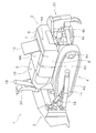
- FIG. 1 is a perspective view of a work vehicle according to an embodiment. It is a side view of a work vehicle. It is a top view of a work vehicle. It is a block diagram which shows the structure of a work vehicle. It is a block diagram which shows the structure of the control system of a work vehicle. It is a flowchart which shows the process of vehicle speed automatic adjustment control. It is a timing chart which shows the change of the acceleration and engine rotation speed in vehicle speed automatic adjustment control. It is a flowchart which shows the process of the vehicle speed automatic adjustment control which concerns on a modification. It is a perspective view of the work vehicle which concerns on a modification.
- FIG. 1 is a perspective view of a work vehicle 1 according to the embodiment.
- FIG. 2 is a side view of the work vehicle 1.
- FIG. 3 is a plan view of the work vehicle 1.
- the work vehicle 1 is a bulldozer.
- the work vehicle 1 is a vehicle that does not include a cab. As will be described later, the work vehicle 1 can be remotely operated.
- the work vehicle 1 includes a vehicle main body 2 and a work implement 3.
- the vehicle body 2 includes a traveling device 4 and an engine room 5.
- the traveling device 4 is a device for causing the work vehicle 1 to travel.
- the traveling device 4 includes crawler belts 4a and 4b and drive wheels 4c and 4d.
- the crawler belt 4 a is provided on the left side of the vehicle body 2.
- the crawler belt 4 b is provided on the right side portion of the vehicle main body 2.
- a part of the crawler belt 4a is wound around the drive wheel 4c.
- a part of the crawler belt 4b is wound around the drive wheel 4d.
- the work vehicle 1 travels when the crawler belts 4a and 4b are driven by the rotation of the drive wheels 4c and 4d.
- the front means the direction where the working machine 3 is arrange
- left and right shall mean the right and left direction in the state which faced the above-mentioned front.
- the engine room 5 is arranged on the front part of the vehicle body 2.
- An engine 11 (see FIG. 4) is disposed in the engine chamber 5.
- the vehicle main body 2 has a rear housing portion 6, a right housing portion 7, and a left housing portion 8.
- the engine room 5, the rear housing part 6, the right housing part 7, and the left housing part 8 are arranged so as to surround the maintenance area MA.
- the engine room 5 is disposed in front of the maintenance area MA.
- the rear housing portion 6 is disposed behind the maintenance area MA.
- the right accommodating portion 7 is disposed on the right side of the maintenance area MA.
- the left accommodating portion 8 is disposed on the left side of the maintenance area MA.
- the rear container 6 is a fuel tank.
- a fuel tank may be accommodated in the rear accommodating portion 6.
- a cooling device such as a radiator is disposed in the right accommodating portion 7.
- the left accommodating portion 8 is a hydraulic oil tank.
- a hydraulic oil tank may be accommodated in the left accommodating portion 8.
- the thing accommodated in each accommodating part 6-8 is not restricted to these things, You may change.
- the lid member 10 is disposed above the maintenance area MA.
- the lid member 10 is disposed so that the maintenance area MA can be opened and closed.
- 1 illustrates a state where the lid member 10 is opened
- FIGS. 2 and 3 illustrate a state where the lid member 10 is closed.
- the engine room 5 and the right housing part 7 are provided with doors (not shown) for opening and closing the engine room 5 and the right housing part 7 facing the maintenance area MA.
- the operator can access the engine room 5 and the inside of the right housing part 7 from the maintenance area MA by opening the doors of the engine room 5 and the right housing part 7.
- the work machine 3 is disposed in front of the vehicle body 2.
- the work machine 3 is disposed in front of the engine room 5.
- the work machine 3 is a blade.
- the work machine 3 is supported by the left arm 14 and the right arm 15.
- the left arm 14 is attached to the left side of the vehicle body 2.
- the right arm 15 is attached to the right side of the vehicle body 2.
- the work machine 3 is provided with a left tilt cylinder 16, a right tilt cylinder 17, and a lift cylinder 18.
- the left tilt cylinder 16 is attached to the left side of the vehicle body 2.
- the right tilt cylinder 17 is attached to the left side of the vehicle body 2.
- the left tilt cylinder 16 and the right tilt cylinder 17 are driven by hydraulic oil from the hydraulic pump 12.
- the left tilt cylinder 16 and the right tilt cylinder 17 operate the working machine 3 to the left and right.
- the lift cylinder 18 is attached to the center of the vehicle body 2 in the vehicle width direction.
- the lift cylinder 18 is attached to the vehicle main body 2 while being inclined in the front-rear direction of the vehicle main body 2.
- only one lift cylinder 18 is provided.
- the lift cylinder 18 is disposed in front of the engine compartment 5.
- the lift cylinder 18 is disposed behind the work machine 3.
- the lift cylinder 18 is driven by hydraulic oil from the hydraulic pump 12.
- the lift cylinder 18 moves the work machine 3 up and down.
- a horn 33 is attached to the front of the vehicle body 2.
- the horn 33 is disposed in front of the engine compartment 5.
- the horn 33 extends to a position above the work machine 3.
- the horn 33 extends to a position above the engine chamber 5.
- Work vehicle 1 includes a ripper device 31.
- the ripper device 31 is disposed behind the vehicle body 2.
- the ripper device 31 is attached to the vehicle body 2.
- the ripper device 31 may be omitted.
- FIG. 4 is a block diagram showing the configuration of the work vehicle 1.
- the work vehicle 1 includes an engine 11, a hydraulic pump 12, and a pump capacity control device 19.
- the engine 11 is provided with a fuel supply device 34 and an engine rotation speed sensor 35.
- the fuel supply device 34 controls the amount of fuel supplied to the engine 11.
- the engine rotation speed is controlled by controlling the amount of fuel supplied to the engine 11 by the fuel supply device 34.
- the engine rotation speed sensor 35 detects the rotation speed of the engine.
- the hydraulic pump 12 is driven by the engine 11 to discharge hydraulic oil.
- the hydraulic pump 12 is a variable displacement pump, and the pump displacement control device 19 controls the discharge displacement of the hydraulic pump 12.
- the work vehicle 1 has a work implement control valve 20 and a hydraulic actuator 21.
- the hydraulic actuator 21 is driven by the hydraulic oil discharged from the hydraulic pump 12.
- the hydraulic actuator 21 includes the lift cylinder 18 and the left and right tilt cylinders 16 and 17 described above.
- the work machine control valve 20 controls supply and discharge of hydraulic oil to the hydraulic actuator 21.
- the work vehicle 1 has a PTO (Power take-off) 36, a power transmission device 13, and a clutch control valve 22.
- the PTO 36 distributes the driving force of the engine 11 to the hydraulic pump 12 and the power transmission device 13.
- the power transmission device 13 includes, for example, a transmission and a torque converter.
- the power transmission device 13 transmits the driving force from the engine 11 to the drive wheels 4 c and 4 d via the final reduction gear 37.
- the clutch control valve 22 controls switching of a shift clutch, a forward / reverse clutch, a steering clutch, and the like included in the power transmission device 13.
- the work vehicle 1 has an imaging device 23.
- the imaging device 23 acquires an image around the work vehicle 1.
- the imaging device 23 outputs a detection signal indicating the acquired image.
- the imaging device 23 has a plurality of cameras 41-45 shown in FIGS. As shown in FIG. 2, the plurality of cameras 41 and 45 are attached to the horn 33. As shown in FIG. 3, the plurality of cameras 42-44 are attached to the left side, right side, and rear part of the vehicle body 2, respectively.
- the work vehicle 1 has an acceleration detection device 38.
- the acceleration detection device 38 detects the acceleration of the work vehicle 1.
- the acceleration detection device 38 is a multi-axis acceleration detection device that detects accelerations in a plurality of different directions. Specifically, the acceleration detection device 38 detects the vertical acceleration, the horizontal acceleration, and the longitudinal acceleration of the work vehicle 1.
- the acceleration detection device 38 is a three-axis acceleration sensor or an IMU (Inertial Measurement Unit).
- the acceleration detection device 38 is arranged at the center of gravity of the work vehicle 1 or a place close to the center of gravity.
- the acceleration detection device 38 detects the acceleration of the vehicle in three different directions described above in real time and outputs a detection signal thereof.
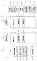
- FIG. 5 is a block diagram showing the configuration of the control system for the work vehicle 1.
- the control system of the work vehicle 1 has a remote control system 26.
- the remote control system 26 is disposed, for example, at a base at a location away from the work site where the work vehicle 1 is working. Alternatively, the remote control system 26 may be portable and located at a work site.
- the remote control system 26 includes a communication device 27 and a remote controller 28.
- the work vehicle 1 includes a vehicle controller 24 and a communication device 25.
- the communication device 25 of the work vehicle 1 is connected to an antenna 39 (see FIG. 1) mounted on the vehicle body 2.
- the communication device 25 of the work vehicle 1 communicates with the communication device 27 of the remote control system 26 by radio.
- the vehicle controller 24 includes a calculation device 41 such as a CPU and a storage device 42.
- the storage device 42 is configured by, for example, a memory such as a RAM or a ROM, or a storage device such as a hard disk.
- the vehicle controller 24 is programmed to control the work vehicle 1 based on a command signal from the remote control system 26.
- the vehicle controller 24 receives detection signals such as the engine rotation speed detected by the engine rotation speed sensor 35, the image captured by the imaging device 23, and the acceleration detected by the acceleration detection device 38.
- the vehicle controller 24 transmits the received detection signal to the communication device 27 of the remote control system 26 via the communication device 25.
- the remote controller 28 receives a detection signal from the vehicle controller 24 via the communication device 27.
- the remote controller 28 has a calculation device 43 such as a CPU and a storage device 44.
- the storage device 44 is configured by a memory such as a RAM or a ROM, or a storage device such as a hard disk.
- the remote control system 26 includes a remote control device 29 and a display device 30.
- the display device 30 is configured by a display such as a CRT, LCD, or OELD, for example.
- the display device 30 is not limited to these displays, and may be other types of displays.
- the remote controller 28 is programmed to generate a display image showing the periphery of the work vehicle 1 based on the detection signal indicating the image acquired by the imaging device 23 and display the display image on the display device 30.
- the operator can operate the work vehicle 1 at a place away from the work vehicle 1 by operating the remote control device 29 while viewing the display image.
- the remote control device 29 includes a throttle operation member 45, a turning operation member 46, a deceleration operation member 47, and a work implement operation member 48.
- the throttle operation member 45 is an operation member for setting the engine speed. The operator can set the engine speed to a desired value by operating the throttle operation member 45.
- the turning operation member 46 is an operation member for turning the work vehicle 1 left and right.
- the operator can turn the work vehicle 1 left and right by operating the turning operation member 46.
- the deceleration operation member 47 is an operation member for adjusting the vehicle speed of the work vehicle 1.
- the operator can reduce the vehicle speed of the work vehicle 1 by operating the deceleration operation member 47.
- the work machine operation member 48 is an operation member for operating the work machine 3. The operator can perform operations such as a tilt operation of the work machine 3 by operating the work machine operation member 48.
- the remote controller 28 transmits a command signal indicating the operation content by the remote control device 29 to the communication device 25 of the work vehicle 1 via the communication device 27.
- the vehicle controller 24 receives a command signal from the remote controller 28 via the communication device 25.
- the vehicle controller 24 outputs a command signal to the fuel supply device 34, the pump capacity control device 19, the clutch control valve 22, and the work implement control valve 20 of the work vehicle 1 based on the command signal from the remote controller 28.
- the control system for the work vehicle 1 executes vehicle speed automatic adjustment control that appropriately controls the vehicle speed according to the acceleration value detected by the acceleration detection device 38.
- vehicle speed automatic adjustment control will be described.
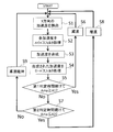
- FIG. 6 is a flowchart showing a process of automatic vehicle speed adjustment control.
- step S1 when the work vehicle 1 starts traveling, acceleration in three directions is detected in step S1.
- the remote controller 28 receives detection signals indicating the vertical acceleration, the horizontal acceleration, and the longitudinal acceleration of the work vehicle 1 detected by the acceleration detection device 38.
- step S2 the remote controller 28 performs high-pass filter processing on the accelerations in the vertical, horizontal, and longitudinal directions. Thereby, the gravity acceleration component contained in each acceleration is removed.
- step S3 the remote controller 28 synthesizes accelerations in the vertical, horizontal, and longitudinal directions.
- acceleration is synthesized by the following equation.
- Ama is the synthesized acceleration.
- Ax is the acceleration in the lateral direction of the vehicle
- Ay is the acceleration in the longitudinal direction of the vehicle
- Az is the acceleration in the vertical direction of the vehicle.
- step S4 the remote controller 28 performs low-pass filter processing on the synthesized acceleration Ama. Since the low-pass filter process smoothes the waveform of the synthesized acceleration Ama, the calculation load on the remote controller 28 can be reduced.
- step S5 the remote controller 28 determines whether or not the synthesized acceleration Ama after the low-pass filter processing is equal to or greater than the first threshold value A1.
- the first threshold A1 is stored in the storage device 42.
- the comparison between the acceleration Ama and the first threshold value A1 is continuously performed for a predetermined first determination time (for example, 1 second).
- step S6 the remote controller 28 reduces the vehicle speed. Specifically, the remote controller 28 outputs a command signal for reducing the engine speed. The vehicle controller 24 outputs a command signal to the fuel supply device 34 based on the command signal from the remote controller 28. Thereby, the engine speed is reduced.
- step S5 when the acceleration Ama is larger than the first threshold value A1, the process proceeds to step S7.
- the process proceeds to step S7 also when the state where the acceleration Ama is equal to or greater than the first threshold A1 is not continuous during the first determination time.
- the remote controller 28 determines whether or not the acceleration Ama is equal to or less than the second threshold value A2.
- the second threshold A2 is a value smaller than the first threshold A1.
- the second threshold A2 is calculated by multiplying the first threshold A1 by a constant r (r ⁇ 1).
- the second threshold value A2 may be a value stored in the storage device 42 instead of being calculated.
- the comparison between the acceleration Ama and the second threshold value A2 is continuously performed during a predetermined second determination time.
- the second determination time may be the same time as the first determination time.
- the second determination time may be a time different from the first determination time.
- step S8 the remote controller 28 increases the vehicle speed. Specifically, the remote controller 28 outputs a command signal for increasing the engine speed. The vehicle controller 24 outputs a command signal to the fuel supply device 34 based on the command signal from the remote controller 28. Thereby, the engine rotation speed is increased.
- step S7 when the acceleration Ama is larger than the second threshold A2, the process proceeds to step S9.
- step S9 the process proceeds to step S9 even when the state where the acceleration Ama is equal to or less than the second threshold value A2 is not continuous during the second determination time.
- step S9 the vehicle speed is maintained at the current speed. That is, when the vehicle speed is smaller than the first threshold A1 and larger than the second threshold A2, the vehicle speed is maintained at the current speed.
- the predetermined change stop time and the change of the vehicle speed are not performed from the time when the change of the vehicle speed is completed, that is, the change of the engine rotation speed is completed.
- the vehicle speed may not be changed by stopping the determination based on the acceleration during the change stop time.
- the change in the vehicle speed may be prohibited by prohibiting the change in the vehicle speed even if the determination based on the acceleration is performed.
- the above vehicle speed automatic adjustment control is executed both when the work vehicle 1 moves forward and when it moves backward.
- the vehicle speed automatic adjustment control is executed when the work vehicle 1 travels for movement without performing work by the work machine 3.
- the vehicle speed automatic adjustment control is canceled. Specifically, when either the decel operation member 47 or the turning operation member 46 is operated at the base, the vehicle controller 24 cancels the vehicle speed automatic control based on the acceleration determination during the operation.
- FIG. 7 is a timing chart showing changes in acceleration and engine rotation speed in vehicle speed automatic adjustment control.
- the acceleration shown in FIG. 7 is a synthesized acceleration after the low-pass filter processing described above.
- the engine 11 is started.
- the engine speed is set to the maximum speed Nmax by the throttle operation member 45.
- the automatic vehicle speed adjustment control is not started from time T0 to T2, and the automatic vehicle speed adjustment control is started from time T2. Accordingly, during the period from time T2 to T3, the remote controller 28 determines acceleration. From time T2 to T3, the acceleration is equal to or less than the second threshold A2. However, since the engine rotational speed is set to the maximum rotational speed Nmax, no speed increase is performed from time T2 to T3.
- the remote controller 28 outputs a command signal so that the engine speed decreases over time T5 to T6. Specifically, the remote controller 28 reduces the engine speed to a value N1 that is a predetermined amount dN lower than the current value Nmax. Thereby, the vehicle speed is reduced.
- the engine rotation speed is not changed during the period from the time T6 when the reduction of the engine rotation speed is completed to the time T9 (change stop time). Therefore, during the period from time T6 to time T9, the engine speed is maintained at N1 even if the acceleration is equal to or higher than the first threshold value A1 continuously during the first determination time.
- the remote controller 28 After the change stop time has elapsed, the acceleration is continuously greater than or equal to the first threshold value A1 from time T9 to T10 (first determination time). Therefore, over a period from time T10 to T11, the remote controller 28 reduces the engine rotation speed to a value N2 that is reduced by a predetermined amount dN from the current value N1. Thereby, the vehicle speed is further reduced.
- the engine rotation speed is not changed during the period from the time T11 to the time T14 when the reduction of the engine rotation speed is completed (change stop time). Therefore, during the period from time T11 to time T14, the engine speed is maintained at N2 even if the acceleration continuously falls below the second threshold A2 during the second determination time.
- the remote controller 28 increases the engine speed to a value N1 that is increased by a predetermined amount dN from the current value N2 over a period of time T15 to T16. As a result, the vehicle speed increases.
- the engine rotation speed is not changed during the period from the time T16 when the reduction of the engine rotation speed is completed to the time T19 (change stop time). Then, after the change stop time has elapsed, the acceleration is continuously equal to or less than the second threshold value A2 from time T19 to T20 (second determination time). Therefore, the remote controller 28 increases the engine speed to a value Nmax that is increased by a predetermined amount dN from the current value N1 over a period of time T20 to T21. This further increases the vehicle speed.
- the engine rotation speed is not changed during the period from the time T21 when the reduction of the engine rotation speed is completed to the time T24 (change stop time). Then, after the change stop time has elapsed, during the period from time T24 to time T25, the acceleration is smaller than the first threshold A1 and larger than the second threshold A2. Alternatively, the state where the acceleration is equal to or higher than the first threshold A1 is not continuous during the first determination time. Therefore, the engine speed is maintained at the current value Nmax from time T24 to time T25.
- the remote controller 28 reduces the engine speed to a value N1 that is reduced by a predetermined amount dN from the current value Nmax over time T26 to T27. Thereby, the vehicle speed is reduced.
- the engine rotation speed is not changed during the period from the time T27 when the reduction of the engine rotation speed is completed to the time T30 (change stop time). Then, after the change stop time has elapsed, during the period from time T30 to time T32, the acceleration is smaller than the first threshold A1 and larger than the second threshold A2. Alternatively, the state in which the acceleration is equal to or less than the second threshold A2 is not continuous during the second determination time. Therefore, the engine speed is maintained at the current value N1 from time T30 to time T32.
- the vehicle speed is adjusted according to the acceleration value by the vehicle speed automatic adjustment control.
- the vehicle speed automatic adjustment control when the work vehicle 1 is traveling, if the road surface is uneven, the vehicle posture changes, resulting in acceleration in the vehicle. The value of this acceleration changes according to the degree of unevenness on the road surface. For this reason, the degree of unevenness on the road surface can be detected from the acceleration value. Therefore, according to the vehicle speed automatic adjustment control described above, the vehicle speed can be appropriately controlled according to the degree of unevenness of the road surface by adjusting the vehicle speed according to the acceleration value.
- the vehicle speed is reduced when the acceleration is continuously greater than or equal to the first threshold value A1 during the first determination time.
- the vehicle speed is automatically reduced, and it is possible to suppress unnecessary shocks to the vehicle.
- the vehicle speed is increased. Therefore, when the work vehicle 1 travels on terrain with a small undulation, work efficiency can be improved by preventing meaningless low-speed travel.
- a bulldozer is illustrated as the work vehicle 1, but other types of vehicles such as a dump truck, a wheel loader, and a hydraulic excavator may be used.
- FIG. 8 is a flowchart showing processing of automatic vehicle speed adjustment control according to a modification. As shown in FIG. 8, the high-pass filter process in step S2 described above may be omitted. Alternatively, the low-pass filter process in step S4 described above may be omitted.
- a moving average process may be performed on the synthesized acceleration.
- the moving average process is to take an average of a plurality of data in order to remove fluctuation noise of time series data.
- the remote controller 28 records the synthesized acceleration value in the storage device 44 in time series.
- the remote controller 28 performs a moving average process on the synthesized acceleration value in real time using the recorded acceleration value.
- step S14 it is determined whether the moving average processed acceleration is continuously equal to or higher than the first threshold A1 during the first determination time.
- step S16 it is determined whether the acceleration subjected to the moving average process is continuously equal to or less than the second threshold A2 during the second determination time.
- steps S11, S12, S15, S17, and S18 are the same as steps S1, S3, S6, S8, and S9 of the above-described embodiment.
- the vertical acceleration, the horizontal acceleration, and the front-rear acceleration of the work vehicle 1 are combined, but only one of them may be used for the determination. Alternatively, an acceleration obtained by combining two of these may be used for the determination.
- the acceleration used for the determination preferably includes at least the vertical acceleration of the work vehicle 1.
- the vehicle speed automatic adjustment control is temporarily released when the decel operation is performed.
- the adjustment control since the acceleration caused by the deceleration operation has a slight effect on the determination in steps S5 and S7, the adjustment control does not have to be released. The influence is slight because the time when the acceleration due to the deceleration operation occurs is shorter than the first and second determination times for comparing the magnitude of the acceleration Ama and the thresholds A1 and A2.
- the adjustment control since the acceleration accompanying the deceleration operation is a high frequency, the adjustment control may be continued by removing the acceleration by a low-pass filter process.
- the remote controller 28 is controlled to reduce the vehicle speed when the combined acceleration Ama is equal to or higher than the first threshold A1 for the first determination time. However, the vehicle speed may be reduced when the combined acceleration Ama is greater than the first threshold value A1. Similarly, in the above embodiment, the remote controller 28 performs control to increase the vehicle speed when the resultant acceleration Ama is continuously equal to or lower than the second threshold value A2 during the second determination time. However, the vehicle speed may be increased when the combined acceleration Ama is smaller than the second threshold value A2.
- the structure of the work vehicle 1 is not limited to that of the above embodiment, and may be changed.
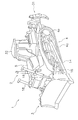
- the work vehicle 1 may be a vehicle including a driver seat 32 as shown in FIG.
- the work vehicle 1 is not limited to a vehicle that can be remotely operated, and may be a vehicle that can be operated at the driver's seat 32.
- the present invention by appropriately adjusting the vehicle speed in accordance with the road surface state, it is possible to suppress a decrease in work efficiency and to prevent excessively large vibrations from being continuously applied to the vehicle.
Landscapes
- Engineering & Computer Science (AREA)
- General Engineering & Computer Science (AREA)
- Mechanical Engineering (AREA)
- Chemical & Material Sciences (AREA)
- Combustion & Propulsion (AREA)
- Mining & Mineral Resources (AREA)
- Civil Engineering (AREA)
- Structural Engineering (AREA)
- Transportation (AREA)
- Automation & Control Theory (AREA)
- Operation Control Of Excavators (AREA)
- Control Of Vehicle Engines Or Engines For Specific Uses (AREA)
Abstract
Priority Applications (3)
| Application Number | Priority Date | Filing Date | Title |
|---|---|---|---|
| US15/540,292 US11255074B2 (en) | 2015-03-10 | 2016-03-03 | Control system for work vehicle, control method, and work vehicle |
| AU2016230236A AU2016230236B2 (en) | 2015-03-10 | 2016-03-03 | Control system for work vehicle, control method, and work vehicle |
| JP2017505285A JPWO2016143670A1 (ja) | 2015-03-10 | 2016-03-03 | 作業車両の制御システム、制御方法、および作業車両 |
Applications Claiming Priority (2)
| Application Number | Priority Date | Filing Date | Title |
|---|---|---|---|
| US201562130867P | 2015-03-10 | 2015-03-10 | |
| US62/130867 | 2015-03-10 |
Publications (1)
| Publication Number | Publication Date |
|---|---|
| WO2016143670A1 true WO2016143670A1 (fr) | 2016-09-15 |
Family
ID=56880130
Family Applications (1)
| Application Number | Title | Priority Date | Filing Date |
|---|---|---|---|
| PCT/JP2016/056635 Ceased WO2016143670A1 (fr) | 2015-03-10 | 2016-03-03 | Système de commande pour engin de chantier, procédé de commande et engin de chantier |
Country Status (4)
| Country | Link |
|---|---|
| US (1) | US11255074B2 (fr) |
| JP (1) | JPWO2016143670A1 (fr) |
| AU (1) | AU2016230236B2 (fr) |
| WO (1) | WO2016143670A1 (fr) |
Cited By (3)
| Publication number | Priority date | Publication date | Assignee | Title |
|---|---|---|---|---|
| CN108005798A (zh) * | 2017-11-07 | 2018-05-08 | 湖北三江航天万峰科技发展有限公司 | 一种基于dsp处理器的柴油机远程控制装置 |
| WO2019189935A1 (fr) * | 2018-03-31 | 2019-10-03 | 住友建機株式会社 | Pelle |
| WO2025070110A1 (fr) * | 2023-09-27 | 2025-04-03 | 株式会社小松製作所 | Machine de travail et procédé de commande de machine de travail |
Families Citing this family (7)
| Publication number | Priority date | Publication date | Assignee | Title |
|---|---|---|---|---|
| JP7051045B2 (ja) * | 2017-11-08 | 2022-04-11 | オムロン株式会社 | 移動式マニピュレータ、移動式マニピュレータの制御方法及びプログラム |
| US11587366B1 (en) | 2018-11-20 | 2023-02-21 | State Farm Mutual Automobile Insurance Company | Systems and methods for selecting locations to validate automated vehicle data transmission |
| US12259724B2 (en) | 2019-08-27 | 2025-03-25 | Crown Equipment Corporation | Adaptive acceleration for materials handling vehicle |
| US11511743B2 (en) * | 2019-12-17 | 2022-11-29 | Cnh Industrial Canada, Ltd. | System and method for controlling the speed of a work vehicle towing an implement |
| US11919761B2 (en) | 2020-03-18 | 2024-03-05 | Crown Equipment Corporation | Based on detected start of picking operation, resetting stored data related to monitored drive parameter |
| AU2021376026A1 (en) | 2020-11-03 | 2023-06-22 | Crown Equipment Corporation | Adaptive acceleration for materials handling vehicle |
| US20240084553A1 (en) * | 2022-09-14 | 2024-03-14 | Caterpillar Inc. | System and method for communicating machine impacts to remote operator workstation |
Citations (1)
| Publication number | Priority date | Publication date | Assignee | Title |
|---|---|---|---|---|
| JP2002521272A (ja) * | 1998-07-29 | 2002-07-16 | コンティネンタル・テーベス・アクチエンゲゼルシヤフト・ウント・コンパニー・オッフェネ・ハンデルスゲゼルシヤフト | 車両走行路の悪路区間の検出および速度制御のための方法と装置 |
Family Cites Families (7)
| Publication number | Priority date | Publication date | Assignee | Title |
|---|---|---|---|---|
| JP3269421B2 (ja) * | 1997-04-04 | 2002-03-25 | 三菱自動車工業株式会社 | 車両の自動減速制御装置 |
| JP3986939B2 (ja) * | 2002-10-25 | 2007-10-03 | 本田技研工業株式会社 | 車両用ブレーキ装置 |
| US7739019B2 (en) * | 2004-12-20 | 2010-06-15 | Gm Global Technology Operations, Inc. | Rough road detection |
| US8544966B2 (en) * | 2008-01-17 | 2013-10-01 | Advics Co., Ltd. | Brake controller for vehicle and brake control method for vehicle |
| JP5586568B2 (ja) | 2011-11-15 | 2014-09-10 | 株式会社小松製作所 | 建設機械の情報表示装置、建設機械の情報表示方法及び建設機械の情報表示用コンピュータプログラム |
| US9248837B2 (en) * | 2014-03-11 | 2016-02-02 | Tata Consultancy Services Limited | Method and system for controlling a speed of a vehicle |
| KR101628830B1 (ko) * | 2014-11-14 | 2016-06-09 | 현대모비스 주식회사 | 차량 승객 보호 장치 및 방법 |
-
2016
- 2016-03-03 WO PCT/JP2016/056635 patent/WO2016143670A1/fr not_active Ceased
- 2016-03-03 JP JP2017505285A patent/JPWO2016143670A1/ja active Pending
- 2016-03-03 US US15/540,292 patent/US11255074B2/en active Active
- 2016-03-03 AU AU2016230236A patent/AU2016230236B2/en active Active
Patent Citations (1)
| Publication number | Priority date | Publication date | Assignee | Title |
|---|---|---|---|---|
| JP2002521272A (ja) * | 1998-07-29 | 2002-07-16 | コンティネンタル・テーベス・アクチエンゲゼルシヤフト・ウント・コンパニー・オッフェネ・ハンデルスゲゼルシヤフト | 車両走行路の悪路区間の検出および速度制御のための方法と装置 |
Cited By (8)
| Publication number | Priority date | Publication date | Assignee | Title |
|---|---|---|---|---|
| CN108005798A (zh) * | 2017-11-07 | 2018-05-08 | 湖北三江航天万峰科技发展有限公司 | 一种基于dsp处理器的柴油机远程控制装置 |
| CN108005798B (zh) * | 2017-11-07 | 2020-06-02 | 湖北三江航天万峰科技发展有限公司 | 一种基于dsp处理器的柴油机远程控制装置 |
| WO2019189935A1 (fr) * | 2018-03-31 | 2019-10-03 | 住友建機株式会社 | Pelle |
| CN112368449A (zh) * | 2018-03-31 | 2021-02-12 | 住友建机株式会社 | 挖土机 |
| JPWO2019189935A1 (ja) * | 2018-03-31 | 2021-03-25 | 住友建機株式会社 | ショベル |
| JP7307051B2 (ja) | 2018-03-31 | 2023-07-11 | 住友建機株式会社 | ショベル |
| US12018461B2 (en) | 2018-03-31 | 2024-06-25 | Sumitomo Construction Machinery Co., Ltd. | Shovel |
| WO2025070110A1 (fr) * | 2023-09-27 | 2025-04-03 | 株式会社小松製作所 | Machine de travail et procédé de commande de machine de travail |
Also Published As
| Publication number | Publication date |
|---|---|
| JPWO2016143670A1 (ja) | 2017-12-21 |
| AU2016230236B2 (en) | 2019-07-25 |
| AU2016230236A1 (en) | 2017-07-20 |
| US20180002894A1 (en) | 2018-01-04 |
| US11255074B2 (en) | 2022-02-22 |
Similar Documents
| Publication | Publication Date | Title |
|---|---|---|
| JPWO2016143670A1 (ja) | 作業車両の制御システム、制御方法、および作業車両 | |
| JP7474102B2 (ja) | ショベル及びその制御方法 | |
| JP5285805B1 (ja) | ブレード制御装置、作業機械及びブレード制御方法 | |
| CN104302843B (zh) | 机器的防振颤控制系统 | |
| JP5285815B1 (ja) | ブレード制御システム、建設機械及びブレード制御方法 | |
| JP7245723B2 (ja) | トラックの荷台重心位置制御装置 | |
| JP7514077B2 (ja) | ショベル | |
| CA3033191C (fr) | Systeme de commande pour engin de chantier, procede de commande et engin de chantier | |
| JP6266809B1 (ja) | 作業車両および作業車両の管理システム | |
| JP2018001901A (ja) | 走行支援装置 | |
| JP6736597B2 (ja) | ホイールローダ | |
| JP2015190159A (ja) | ショベル及びその制御方法 | |
| JP5513818B2 (ja) | 産業用車両 | |
| CN105164343B (zh) | 确定有效载荷装载事件在牵引机器中何时发生的方法 | |
| JP2018071255A (ja) | 作業車両の制御システム、制御方法、及び作業車両 | |
| CN105074157B (zh) | 作业车辆 | |
| US20160236606A1 (en) | Method for controlling hoisting of an articulated machine | |
| JP7340379B2 (ja) | ホイール式の作業車両 | |
| WO2016092868A1 (fr) | Engin de chantier | |
| CN108501650A (zh) | 用于机动车辆的动态可调车身座架 | |
| JP2009023595A (ja) | 運搬車両のサスペンション装置 | |
| WO2024190473A1 (fr) | Engin de chantier et procédé de commande pour engin de chantier |
Legal Events
| Date | Code | Title | Description |
|---|---|---|---|
| 121 | Ep: the epo has been informed by wipo that ep was designated in this application |
Ref document number: 16761640 Country of ref document: EP Kind code of ref document: A1 |
|
| ENP | Entry into the national phase |
Ref document number: 2017505285 Country of ref document: JP Kind code of ref document: A |
|
| WWE | Wipo information: entry into national phase |
Ref document number: 15540292 Country of ref document: US |
|
| ENP | Entry into the national phase |
Ref document number: 2016230236 Country of ref document: AU Date of ref document: 20160303 Kind code of ref document: A |
|
| NENP | Non-entry into the national phase |
Ref country code: DE |
|
| 122 | Ep: pct application non-entry in european phase |
Ref document number: 16761640 Country of ref document: EP Kind code of ref document: A1 |