WO2016143893A1 - Stent en résine synthétique - Google Patents
Stent en résine synthétique Download PDFInfo
- Publication number
- WO2016143893A1 WO2016143893A1 PCT/JP2016/057773 JP2016057773W WO2016143893A1 WO 2016143893 A1 WO2016143893 A1 WO 2016143893A1 JP 2016057773 W JP2016057773 W JP 2016057773W WO 2016143893 A1 WO2016143893 A1 WO 2016143893A1
- Authority
- WO
- WIPO (PCT)
- Prior art keywords
- stent
- biodegradable
- fibers
- diameter
- synthetic resin
- Prior art date
- Legal status (The legal status is an assumption and is not a legal conclusion. Google has not performed a legal analysis and makes no representation as to the accuracy of the status listed.)
- Ceased
Links
Images


Classifications
-
- A—HUMAN NECESSITIES
- A61—MEDICAL OR VETERINARY SCIENCE; HYGIENE
- A61F—FILTERS IMPLANTABLE INTO BLOOD VESSELS; PROSTHESES; DEVICES PROVIDING PATENCY TO, OR PREVENTING COLLAPSING OF, TUBULAR STRUCTURES OF THE BODY, e.g. STENTS; ORTHOPAEDIC, NURSING OR CONTRACEPTIVE DEVICES; FOMENTATION; TREATMENT OR PROTECTION OF EYES OR EARS; BANDAGES, DRESSINGS OR ABSORBENT PADS; FIRST-AID KITS
- A61F2/00—Filters implantable into blood vessels; Prostheses, i.e. artificial substitutes or replacements for parts of the body; Appliances for connecting them with the body; Devices providing patency to, or preventing collapsing of, tubular structures of the body, e.g. stents
- A61F2/82—Devices providing patency to, or preventing collapsing of, tubular structures of the body, e.g. stents
- A61F2/86—Stents in a form characterised by the wire-like elements; Stents in the form characterised by a net-like or mesh-like structure
- A61F2/90—Stents in a form characterised by the wire-like elements; Stents in the form characterised by a net-like or mesh-like structure characterised by a net-like or mesh-like structure
Definitions
- the present invention relates to a synthetic resin stent such as a biodegradable stent.
- a treatment for expanding the stenotic part by placing a stent in the stenotic part has been performed.
- stents for example, metal or synthetic resin stents are known (see, for example, Patent Documents 1 to 3).
- a metal stent requires a surgical operation when being extracted from the body, a great burden is placed on the patient. Therefore, the use of a metal stent is limited when it is used for a case such as a malignant tumor in which semi-permanent placement or surgery is planned. From such a background, a biodegradable stent as a synthetic resin stent has been proposed as a stent to be used for cases where a metal stent cannot be used.
- the biodegradable stent is formed into a cylindrical shape by weaving biodegradable fibers, and is decomposed over time in blood vessels and gastrointestinal tracts, so that removal of the stent from the body is unnecessary.
- Biodegradable stents are expected to reduce the burden on patients by using them particularly for benign stenotic diseases.
- the stent is placed in the stenosis portion by making the stenosis portion approach the stenosis portion in a reduced diameter state and then expanding the diameter in the stenosis portion.
- the restoring force to the expanded state is weakened due to, for example, creases in the fibers at the end of the stent.
- an object of the present invention is to provide a synthetic resin stent that is unlikely to have a low restoring force from a reduced diameter state to an expanded diameter state.
- the present invention relates to a stent body that is braided into a cylindrical shape by fibers made of synthetic resin and is deformable from a reduced diameter state to an expanded diameter state, and a plurality of the fibers at the end of the stent body.
- An extension portion extending toward the axially outer side of the main body, a bent portion formed by bending a plurality of the fibers on the proximal end side of the extension portion, and a distal end side of the extension portion
- a loop portion formed by connecting two end portions of the fibers, and the two fibers connected in the loop portion are extended from the end portion of the stent body to the extension portion.
- the present invention relates to a synthetic resin stent that intersects at any point.
- the length L of the extending portion and the diameter R of the stent body in the expanded state satisfy the relationship of 0.2R ⁇ L ⁇ 2R.
- the diameter of the synthetic resin stent in the loop portion is preferably larger than the diameter of the synthetic resin stent in the main stent body.
- the synthetic resin stent further includes an extension portion reinforcing member that reinforces the extension portion.
- FIG. 1 is a perspective view showing a biodegradable stent according to a first embodiment of the present invention. It is an expanded view of the edge part in the state which expanded the diameter of the biodegradable stent which concerns on the said embodiment. It is an expanded view of the edge part in the state expanded after reducing the diameter of the biodegradable stent which concerns on the said embodiment. It is an expanded view of the edge part in the state which expanded the diameter of the conventional biodegradable stent. It is an expanded view of the edge part in the state expanded after reducing the diameter of the conventional biodegradable stent. It is a figure which shows an example of the extension part of the biodegradable stent which concerns on 2nd Embodiment of this invention.
- FIG. 1 is a perspective view showing a biodegradable stent 1 as a synthetic resin stent according to this embodiment.
- FIG. 2A is a developed view of the end of the biodegradable stent 1 in an expanded state.
- the synthetic resin stent of the present embodiment is a biodegradable stent 1 composed of biodegradable fibers. As shown in FIG. 1, the stent body 2, the extended portion 3, the bent portion 4, and the loop portion. 5 is provided.
- the stent body 2 is braided into a cylindrical shape by the biodegradable fiber 20 and can be deformed between a reduced diameter state and an expanded diameter state. More specifically, the stent body 2 according to the present embodiment has a large number of rhomboid holes formed by meshing the biodegradable fibers 20 in a mesh shape, and formed by the biodegradable fibers 20 on the outer periphery and regularly arranged. Have.
- the number of biodegradable fibers forming the stent body 2 is 16 in the present embodiment, but is not particularly limited. The number of biodegradable fibers is preferably 16 to 24.
- the size of the stent body 2 is not particularly limited. For example, in the expanded state, the diameter is 5 to 40 mm and the length is 30 to 150 mm.
- the biodegradable fiber 20 is not particularly limited as long as it is a biodegradable fiber.
- the biodegradable fiber 20 is synthesized from monomers such as L-lactic acid, D-lactic acid, DL-lactic acid, ⁇ -caprolactone, ⁇ -butyrolactone, ⁇ -valerolactone, glycolic acid, trimethylene carbonate, and paradioxanone. Examples include homopolymers, copolymers, and blended polymers thereof. In particular, it is preferable to use fibers made of poly-L-lactic acid (PLLA), lactic acid-caprolactone copolymer (P (LA / CL)), or a blend polymer thereof.
- PLLA poly-L-lactic acid
- P LA / CL
- the biodegradable fiber 20 may be a monofilament yarn or a multifilament yarn. Moreover, the biodegradable fiber 20 may be twisted or not.
- the biodegradable fiber 20 is preferably a monofilament yarn from the viewpoint of strengthening the repulsive force against the pressure applied from the radially outer side of the stent body 2 in the narrowed portion in the living body.
- the diameter of the biodegradable fiber 20 is preferably 0.05 to 0.7 mm.
- the diameter of the biodegradable fiber 20 is less than 0.05 mm, the strength of the biodegradable stent 1 tends to decrease.
- the diameter of the biodegradable fiber 20 exceeds 0.7 mm, the diameter in the contracted state increases, so that the biodegradable stent 1 tends to be difficult to be accommodated in a thin tubular member such as a delivery system.
- the upper limit of the diameter of the biodegradable fiber 20 is more preferably 0.3 mm from the viewpoint of being housed in a delivery system having a small inner diameter.
- the lower limit of the diameter of the biodegradable fiber 20 is more preferably 0.2 mm from the viewpoint of maintaining high strength.
- the extended portion 3 is formed by extending a plurality of biodegradable fibers 20 toward the axially outer side of the stent body 2 at the end of the stent body 2.
- the extending portion 3 is formed by extending both ends of the biodegradable fiber 20 while being spaced apart from the shaft outward in the axial direction of the stent body 2.
- the number of loop portions 5 to be formed is not particularly limited, but depends on the number of biodegradable fibers 20 that form the stent body 2 and the extension portion 3. Specifically, in the biodegradable stent 1 according to the present embodiment, since the number of biodegradable fibers 20 forming the stent body 2 is 16, eight loop portions 5 are formed at both ends, respectively.
- the “plurality of biodegradable fibers 20” means that there are a plurality of biodegradable fibers extending in the axial direction of the stent body 2 while paying attention only to the extension portion 3.
- the number of biodegradable fibers forming the biodegradable stent 1 may be one or plural. That is, the “plurality of biodegradable fibers 20” constituting the extending portion 3 may be derived from a single biodegradable fiber or derived from a plurality of biodegradable fibers. It may be.
- the length L of the extension portion 3 and the diameter R of the stent body 2 in the expanded state satisfy the relationship of 0.2R ⁇ L ⁇ 2R.
- the length L of the extending portion 3 is defined as the length from the bending point in the bending portion 4 described later to the tip of the loop portion 5. Further, the length L and the diameter R preferably satisfy the relationship of 0.5R ⁇ L ⁇ 1.5R, and more preferably satisfy the relationship of 0.8R ⁇ L ⁇ 1.5R.
- the bent portion 4 is formed by bending the biodegradable fiber 20 on the proximal end side of the extending portion 3.
- the bent portion 4 is formed at a plurality of locations by bending a plurality (16) of biodegradable fibers 20 forming the stent body 2.
- the “plurality of biodegradable fibers 20” in the extending portion 3 are also bent by focusing only on the bent portions 4. This means that there are a plurality of biodegradable fibers.
- the “plurality of biodegradable fibers 20” that respectively form the plurality of bent portions 4 may be derived from a single biodegradable fiber, or may be derived from a plurality of biodegradable fibers. It may be.
- the loop portion 5 is formed by connecting the end portions of the two biodegradable fibers 20 on the distal end side of the extending portion. More specifically, in the biodegradable stent 1 according to this embodiment, eight loop portions 5 are formed at both ends.
- the loop portion 5 is configured by portions where the biodegradable fibers 20 are curved at both ends of the biodegradable stent 1.
- the “two biodegradable fibers 20” means two biodegradable fibers when only the extending portion 3 is focused, and these “two biodegradable fibers 20”. May be derived from a single biodegradable fiber.
- the diameter of the biodegradable stent 1 in the loop portion 5 is larger than the diameter of the biodegradable stent 1 in the stent body 2. That is, both end sides of the biodegradable stent 1 in the expanded state have a flare shape. Moreover, the two biodegradable fibers 20 connected in the loop part 5 cross in the extension part 3, as shown in FIG.1 and FIG.2A.
- FIG. 2B is a developed view of the end portion of the biodegradable stent 1 in a state where the diameter is expanded after being reduced.
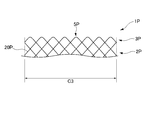
- FIG. 3A is a developed view of an end portion of a conventional biodegradable stent 1P in an expanded state.
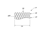
- FIG. 3B is a developed view of the end of the conventional biodegradable stent 1P in a state where the diameter is reduced after being reduced.
- the same configuration as that of the biodegradable stent 1 is denoted by the same reference numeral as that of the biodegradable stent 1, and the description thereof is omitted.
- the biodegradable stent 1P does not include a bent portion formed on the proximal end side of the extending portion 3P.
- the two biodegradable fibers 20P connected at the loop portion 5P do not intersect at the extending portion 3P.
- the biodegradable stent 1 is formed in an elongated cylindrical shape in the reduced diameter state than in the expanded diameter state.
- the biodegradable stent 1 is accommodated in the delivery system in a reduced state.
- the biodegradable stent 1 (stent main body 2) is arrange
- the biodegradable stent 1 is provided with the extending part 3 having a certain length, the diameter of the loop part 5 can be reduced without strongly bending the loop part 5, so that the loop part can be stored even in the delivery system. 5 is difficult to crease at the tip. Further, in the biodegradable stent 1, the two biodegradable fibers 20 connected at the loop portion 5 intersect at the extension portion 3, so that the end of the loop portion 5 is less likely to be folded.
- the biodegradable stent 1 has a circumferential length C1 of the stent body 2 before the crease and a circumferential length of the stent body 2 after the crease. There is almost no difference with C2.
- the conventional biodegradable stent 1P is also strongly folded by being reduced in diameter and housed in the delivery system, and a crease is formed at the tip of the loop portion 5P.
- the circumferential length of the stent body 2 is the length C4 after the end of the loop portion 5P is creased.
- the length C4 is significantly shorter than the circumferential length C3 of the stent body 2 before the end of the loop portion 5P is folded. Therefore, in the conventional biodegradable stent 1P, the restoring force from the reduced diameter state to the expanded diameter state is greatly reduced by forming a crease at the tip of the loop portion 5P.
- the manufacturing method of the biodegradable stent 1 is demonstrated.
- the manufacturing method of the biodegradable stent 1 which concerns on this embodiment is provided with a braiding process and a bending process.
- the biodegradable fiber 20 is braided into a shape having the stent body 2, the extension portion 3, and the loop portion 5 to obtain a cylindrical braided member.
- the base end side of the extended portion 3 of the braided member obtained in the braiding step is bent to form the bent portion 4, and two biodegradable fibers connected at the loop portion 5. 20 crosses. In this way, the biodegradable stent 1 is obtained.
- the biodegradable stent 1 is a stent body 2 braided into a cylindrical shape by the biodegradable fibers 20, and a plurality of biodegradable fibers 20 are formed at the end of the stent body 2.
- An extension part 3 extending toward the axially outer side of the stent body 2, a bent part 4 formed by bending a plurality of biodegradable fibers 20 on the proximal end side of the extension part 3;
- the two biodegradable fibers 20 connected in the loop part 5 were crossed in the extension part 3.
- the biodegradable stent 1 is provided with the extending part 3 having a certain length, the diameter of the loop part 5 can be reduced without strongly bending, so that the loop part can be stored even in the delivery system. 5 is difficult to crease at the tip.
- the two biodegradable fibers 20 connected at the loop portion 5 intersect at the extension portion 3, so that the end of the loop portion 5 is less likely to be folded. Further, even if the end of the loop portion 5 is creased, there is almost no change in the degree of bending of the biodegradable fiber 20 in the bent portion 4. A force is applied in the direction of increasing the length.
- the biodegradable stent 1 has almost no difference between the circumferential length C1 of the stent body 2 before the crease and the circumferential length C2 of the stent body 2 after the crease. .
- the length L of the extending portion 3 and the diameter R of the stent body 2 in the expanded state satisfy the relationship of 0.2R ⁇ L ⁇ 2R.
- L is less than 0.2R, it becomes easier to crease the tip of the loop portion 5.
- L is longer than 2R, the biodegradable fibers 20 are easily entangled with each other in the extending portion 3. Therefore, according to the present embodiment, it is possible to provide a biodegradable stent that has a higher restoring force from the reduced diameter state to the expanded diameter state and that is unlikely to be entangled with each other.
- the diameter of the loop portion 5 is larger than the diameter of the stent body 2 in the state where the diameter of the biodegradable stent 1 is expanded.
- the biodegradable stent of the second embodiment is different from that of the first embodiment in that it includes an extension portion reinforcing tube 6 as an extension portion reinforcing member.
- the same components are denoted by the same reference numerals, and the description thereof is omitted or simplified.
- the extension part reinforcement tube 6 is formed in the tube shape which has a hollow part with the resin member which has a softness
- the extension portion reinforcing tube 6 reinforces the extension portion 3 by inserting one biodegradable fiber 20 out of the biodegradable fibers 20 constituting the extension portion 3 into the hollow portion, and extending the extension portion 3. This prevents the protruding portion 3 from bending in the longitudinal direction and the extending portion 3 from spreading in the width direction.
- the extending portion reinforcing tube 6 is configured to have a size that allows the entire extending portion 3 to be accommodated in the hollow portion, and the entire extending portion 3 is inserted through the hollow portion. May be.
- the biodegradable stent was configured to include the extension portion reinforcing tube 6. Thereby, since the extension part 3 can prevent bending in a longitudinal direction, a biodegradable stent can be detained in a stenosis part more suitably.
- extension part 3 can be prevented from spreading in the width direction, the braided biodegradable stent can be prevented from being unraveled in the extension part.
- the biodegradable stent of the third embodiment is different from that of the second embodiment in that the extension portion reinforcing member is configured by a membrane member.
- the film-like member 7 as an extension part reinforcement member is made into the extension part 3 so that the two biodegradable fibers 20 which comprise the extension part 3 may be connected. Wrapped. Thereby, the elongate oval shape of the extension part 3 is suitably hold
- the biodegradable stent according to the fourth embodiment is different from the second embodiment in that the extending portion reinforcing member is formed of a string-like member.
- the string-like member 8 as an extension part reinforcement member is arrange
- the present invention is not limited to the above-described embodiments, and modifications, improvements, and the like within the scope that can achieve the object of the present invention are included in the present invention. included.
- the two biodegradable fiber 20 connected in the loop part 5 shall cross in the extension part 3, this invention is not limited to this.
- the two biodegradable fibers connected at the loop part may cross at any point from the end of the stent body to the extension part.
- the length of the biodegradable fiber 20 extended in the extension part 3 was made uniform, this invention is not limited to this.
- the length of the biodegradable fiber 20 extending in the extension part 3 is made random, that is, the position of the loop part 5 in the axial direction of the stent body 2 is made random. Can prevent the biodegradable fibers 20 from being entangled with each other.
- a part of the loop portion 5 may be formed in a hook shape, and the loop portion 5 may be hooked on the mesh of the stent body 2 in a state where the diameter of the stent body 2 is expanded. When the stent body 2 is expanded in diameter, the loop portion 5 formed in a hook shape on the mesh of the stent body 2 is hooked, so that the stent body 2 can be fixed in an expanded diameter.
- the biodegradable stent according to the present invention may be a self-expanding stent or a balloon expandable stent.
- the biodegradable stent may be a covered stent.
- the method of placing the biodegradable stent according to the present invention in a stenotic part in the body there is no limitation on the method of placing the biodegradable stent according to the present invention in a stenotic part in the body.
- the balloon may assist in expanding the diameter after approaching the stenosis.
- both end sides of the biodegradable stent in the expanded state are flared, but the present invention is not limited to this.
- the synthetic resin stent in the expanded state may be formed in a cylindrical shape whose both end sides in the longitudinal direction are larger in diameter than the central portion.
- the diameter of the synthetic resin stent in the expanded state may be the same in the longitudinal direction.
- the biodegradable stent 1 is configured by disposing the extending portions 3 at both ends of the stent body 2 in the longitudinal direction.
- the present invention is not limited thereto.
- the synthetic resin stent may be configured by arranging an extending portion only at one end portion in the longitudinal direction of the stent body.
- one extending portion reinforcing tube 6 is disposed in the extending portion 3, but the present invention is not limited to this. That is, each of the two biodegradable fibers may be inserted into the extending portion reinforcing tube, and the two extending portion reinforcing tubes may be disposed in the extending portion.
- the string-like member 8 was arrange
- the end connection part of the two fibers in the present invention is not particularly limited as long as it is a position where the extension part 3 can be formed.
- the method for connecting the ends of the two fibers is not particularly limited, and examples thereof include connection using an adhesive and connection via a connection member.
Landscapes
- Health & Medical Sciences (AREA)
- Engineering & Computer Science (AREA)
- Biomedical Technology (AREA)
- Cardiology (AREA)
- Oral & Maxillofacial Surgery (AREA)
- Transplantation (AREA)
- Heart & Thoracic Surgery (AREA)
- Vascular Medicine (AREA)
- Life Sciences & Earth Sciences (AREA)
- Animal Behavior & Ethology (AREA)
- General Health & Medical Sciences (AREA)
- Public Health (AREA)
- Veterinary Medicine (AREA)
- Media Introduction/Drainage Providing Device (AREA)
Abstract
L'objectif de la présente invention est de fournir un stent en résine synthétique avec lequel une force de rappel, d'un état diamétralement contracté à un état diamétralement dilaté, n'est pas susceptible de diminuer. Ce stent en résine synthétique est pourvu : d'un corps principal de stent 2 qui est tressé en une forme cylindrique à l'aide de fibres de résine synthétique 20, et qui peut se déformer, d'un état diamétralement contracté à un état diamétralement dilaté ; de parties d'extension 3 dans lesquelles une pluralité des fibres 20 s'étend au niveau des parties d'extrémité du corps principal de stent 2 vers la direction axiale à l'extérieur du corps principal de stent 2 ; de parties fléchies 4 dans lesquelles la pluralité de fibres 20 sont formées fléchies, au niveau des côtés d'extrémité de base des parties d'extension 3 ; ainsi que des parties de boucle 5 qui sont formées par réunion des parties d'extrémité de deux fibres 20 au niveau des côtés d'extrémité distale des parties d'extension 3. Les deux fibres 20 réunies par la partie de boucle 5 se croisent l'une l'autre au niveau d'un point quelconque entre la partie d'extrémité du corps principal de stent 2 et la partie d'extension 3.
Priority Applications (1)
| Application Number | Priority Date | Filing Date | Title |
|---|---|---|---|
| JP2017505419A JP6729552B2 (ja) | 2015-03-12 | 2016-03-11 | 合成樹脂ステント |
Applications Claiming Priority (2)
| Application Number | Priority Date | Filing Date | Title |
|---|---|---|---|
| JP2015-049514 | 2015-03-12 | ||
| JP2015049514 | 2015-03-12 |
Publications (1)
| Publication Number | Publication Date |
|---|---|
| WO2016143893A1 true WO2016143893A1 (fr) | 2016-09-15 |
Family
ID=56880032
Family Applications (1)
| Application Number | Title | Priority Date | Filing Date |
|---|---|---|---|
| PCT/JP2016/057773 Ceased WO2016143893A1 (fr) | 2015-03-12 | 2016-03-11 | Stent en résine synthétique |
Country Status (2)
| Country | Link |
|---|---|
| JP (1) | JP6729552B2 (fr) |
| WO (1) | WO2016143893A1 (fr) |
Cited By (1)
| Publication number | Priority date | Publication date | Assignee | Title |
|---|---|---|---|---|
| WO2025074529A1 (fr) * | 2023-10-04 | 2025-04-10 | 朝日インテック株式会社 | Stent |
Citations (4)
| Publication number | Priority date | Publication date | Assignee | Title |
|---|---|---|---|---|
| JP2007536996A (ja) * | 2004-05-14 | 2007-12-20 | ボストン サイエンティフィック リミテッド | ステント溶接プロファイルを減ずる方法、溶接プロファイルを減じたステント、および、閉鎖式ワイヤ構成 |
| JP2009000523A (ja) * | 2007-06-20 | 2009-01-08 | Lab Perouse | 管状プロテーゼおよび関連キット |
| US20130245745A1 (en) * | 2012-03-16 | 2013-09-19 | Microvention, Inc. | Stent and stent delivery device |
| US20140277573A1 (en) * | 2013-03-15 | 2014-09-18 | Merit Medical Systems, Inc. | Esophageal stent |
Family Cites Families (3)
| Publication number | Priority date | Publication date | Assignee | Title |
|---|---|---|---|---|
| JPH1066730A (ja) * | 1996-08-28 | 1998-03-10 | Sumitomo Bakelite Co Ltd | 管腔ステント及びその製造方法 |
| FR2847155B1 (fr) * | 2002-11-20 | 2005-08-05 | Younes Boudjemline | Procede de fabrication d'un implant medical a structure ajouree et implant obtenu par ce procede |
| DE102014115337A1 (de) * | 2014-10-21 | 2016-04-21 | Nasib Dlaikan-Campos | Stent zum Schienen einer Vene und System zum Setzen eines Stents |
-
2016
- 2016-03-11 WO PCT/JP2016/057773 patent/WO2016143893A1/fr not_active Ceased
- 2016-03-11 JP JP2017505419A patent/JP6729552B2/ja active Active
Patent Citations (4)
| Publication number | Priority date | Publication date | Assignee | Title |
|---|---|---|---|---|
| JP2007536996A (ja) * | 2004-05-14 | 2007-12-20 | ボストン サイエンティフィック リミテッド | ステント溶接プロファイルを減ずる方法、溶接プロファイルを減じたステント、および、閉鎖式ワイヤ構成 |
| JP2009000523A (ja) * | 2007-06-20 | 2009-01-08 | Lab Perouse | 管状プロテーゼおよび関連キット |
| US20130245745A1 (en) * | 2012-03-16 | 2013-09-19 | Microvention, Inc. | Stent and stent delivery device |
| US20140277573A1 (en) * | 2013-03-15 | 2014-09-18 | Merit Medical Systems, Inc. | Esophageal stent |
Cited By (1)
| Publication number | Priority date | Publication date | Assignee | Title |
|---|---|---|---|---|
| WO2025074529A1 (fr) * | 2023-10-04 | 2025-04-10 | 朝日インテック株式会社 | Stent |
Also Published As
| Publication number | Publication date |
|---|---|
| JPWO2016143893A1 (ja) | 2017-12-21 |
| JP6729552B2 (ja) | 2020-07-22 |
Similar Documents
| Publication | Publication Date | Title |
|---|---|---|
| JP6764960B2 (ja) | ステント及びカテーテル・ステント・システム | |
| US10092426B2 (en) | Non-foreshortening, axial tension constrainable stent | |
| JP5559063B2 (ja) | 1つ又はそれ以上のトリガワイヤと共に使用するためのステント設計 | |
| JP6806090B2 (ja) | 合成樹脂ステント | |
| EP3189816B1 (fr) | Endoprothèse en résine synthétique | |
| EP2777642B1 (fr) | Endoprothèse tressée avec bague d'expansion | |
| CN102858280A (zh) | 具有生物不可降解端部和用于增大的支架环绕强度的机构的生物可降解支架 | |
| EP3677227B1 (fr) | Stent et dispositif médical le comprenant | |
| JP6543948B2 (ja) | 生分解性ステント | |
| CN102843996A (zh) | 可径向扩张的支架 | |
| JP6729552B2 (ja) | 合成樹脂ステント | |
| EP3949915B1 (fr) | Endoprothèse en résine synthétique | |
| JP7039957B2 (ja) | ステント | |
| JP2017029387A (ja) | 生分解性ステント | |
| JP4920274B2 (ja) | 脈管用ステント | |
| JP2019063522A (ja) | ステント | |
| JP7451876B2 (ja) | ステント | |
| US20230233346A1 (en) | Stent with multiple knitting patterns | |
| JP6880976B2 (ja) | ステント | |
| WO2026070920A1 (fr) | Procédé de fabrication d'implant biomédical et implant biomédical | |
| JP2017169818A (ja) | ステントおよびステントデリバリーシステム | |
| JP2021078620A (ja) | ステント |
Legal Events
| Date | Code | Title | Description |
|---|---|---|---|
| 121 | Ep: the epo has been informed by wipo that ep was designated in this application |
Ref document number: 16761858 Country of ref document: EP Kind code of ref document: A1 |
|
| ENP | Entry into the national phase |
Ref document number: 2017505419 Country of ref document: JP Kind code of ref document: A |
|
| NENP | Non-entry into the national phase |
Ref country code: DE |
|
| 122 | Ep: pct application non-entry in european phase |
Ref document number: 16761858 Country of ref document: EP Kind code of ref document: A1 |