WO2016147236A1 - Dispositif d'éclairage - Google Patents
Dispositif d'éclairage Download PDFInfo
- Publication number
- WO2016147236A1 WO2016147236A1 PCT/JP2015/005978 JP2015005978W WO2016147236A1 WO 2016147236 A1 WO2016147236 A1 WO 2016147236A1 JP 2015005978 W JP2015005978 W JP 2015005978W WO 2016147236 A1 WO2016147236 A1 WO 2016147236A1
- Authority
- WO
- WIPO (PCT)
- Prior art keywords
- light
- image
- projection
- illumination
- illumination light
- Prior art date
- Legal status (The legal status is an assumption and is not a legal conclusion. Google has not performed a legal analysis and makes no representation as to the accuracy of the status listed.)
- Ceased
Links
Images


Classifications
-
- F—MECHANICAL ENGINEERING; LIGHTING; HEATING; WEAPONS; BLASTING
- F21—LIGHTING
- F21S—NON-PORTABLE LIGHTING DEVICES; SYSTEMS THEREOF; VEHICLE LIGHTING DEVICES SPECIALLY ADAPTED FOR VEHICLE EXTERIORS
- F21S2/00—Systems of lighting devices, not provided for in main groups F21S4/00 - F21S10/00 or F21S19/00, e.g. of modular construction
-
- G—PHYSICS
- G03—PHOTOGRAPHY; CINEMATOGRAPHY; ANALOGOUS TECHNIQUES USING WAVES OTHER THAN OPTICAL WAVES; ELECTROGRAPHY; HOLOGRAPHY
- G03B—APPARATUS OR ARRANGEMENTS FOR TAKING PHOTOGRAPHS OR FOR PROJECTING OR VIEWING THEM; APPARATUS OR ARRANGEMENTS EMPLOYING ANALOGOUS TECHNIQUES USING WAVES OTHER THAN OPTICAL WAVES; ACCESSORIES THEREFOR
- G03B21/00—Projectors or projection-type viewers; Accessories therefor
-
- G—PHYSICS
- G03—PHOTOGRAPHY; CINEMATOGRAPHY; ANALOGOUS TECHNIQUES USING WAVES OTHER THAN OPTICAL WAVES; ELECTROGRAPHY; HOLOGRAPHY
- G03B—APPARATUS OR ARRANGEMENTS FOR TAKING PHOTOGRAPHS OR FOR PROJECTING OR VIEWING THEM; APPARATUS OR ARRANGEMENTS EMPLOYING ANALOGOUS TECHNIQUES USING WAVES OTHER THAN OPTICAL WAVES; ACCESSORIES THEREFOR
- G03B21/00—Projectors or projection-type viewers; Accessories therefor
- G03B21/14—Details
-
- H—ELECTRICITY
- H04—ELECTRIC COMMUNICATION TECHNIQUE
- H04N—PICTORIAL COMMUNICATION, e.g. TELEVISION
- H04N5/00—Details of television systems
- H04N5/74—Projection arrangements for image reproduction, e.g. using eidophor
Definitions
- the present invention relates to a lighting device.
- LEDs Light Emitting Diode
- LD Laser Diode
- Patent Literature 1 discloses an illumination device having an illumination function and a video projection function.
- an illumination device having an illumination function and a video projection function
- the present invention has been made to solve such a problem, and an object of the present invention is to provide an illuminating device that can make a lattice pattern appearing in a projection region less noticeable when illuminating light is projected.
- an aspect of an illumination device includes an illumination light / image light generation unit that generates illumination light and image light to be projected onto a predetermined projection area, and illumination that projects the illumination light.
- a projection mode switching unit that switches between a light projection mode and a video light projection mode for projecting the video light; a lens through which the illumination light and the video light pass; and a predetermined projection region by adjusting a position of the lens
- a focus adjustment unit that adjusts the focus of the illumination light and the image light with respect to the lens, and the focus adjustment unit is configured to focus the illumination light on the predetermined projection region in the illumination light projection mode. Adjust the position.
- the present invention it is possible to make the lattice pattern appearing in the projection area less noticeable when the illumination light is projected.
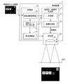
- FIG. 1 is a diagram for explaining an example of use of the illumination device according to the embodiment.
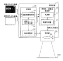
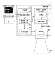
- FIG. 2 is a block diagram illustrating a configuration of the illumination device according to the embodiment.
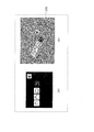
- FIG. 3A is a diagram illustrating an example of an input image for video input to the lighting device, and
- FIG. 3B is a diagram illustrating video light in a projection area based on the input image illustrated in FIG. It is a figure which shows a mode when projecting.
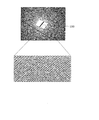
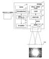
- FIG. 4A is a diagram illustrating an example of an input image for illumination input to the illumination device, and
- FIG. 4B is a diagram illustrating illumination light on a projection region based on the input image illustrated in FIG. It is a figure which shows a mode when projecting.
- FIG. 1 is a diagram for explaining an example of use of the illumination device according to the embodiment.
- FIG. 2 is a block diagram illustrating a configuration of the illumination device according to the embodiment.
- FIG. 3A is a diagram illustrating an example of an input image for video
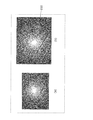
- FIG. 5 is a diagram illustrating a state when illumination light is projected by a conventional illumination device.
- FIG. 6 is a diagram for explaining the operation of the illumination apparatus according to the embodiment in the image light projection mode.
- FIG. 7 is a diagram for explaining the operation of the illumination apparatus according to the embodiment in the illumination light projection mode.
- FIG. 8 is a diagram for explaining another operation of the illumination device according to the embodiment in the illumination light projection mode.
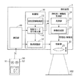
- FIG. 9 is a block diagram illustrating a configuration of a lighting device according to the first modification.
- FIG. 10 is a block diagram illustrating a configuration of a lighting device according to the second modification.
- FIG. 1 is a diagram for explaining an example of use of the illumination device according to the embodiment.
- FIG. 2 is a block diagram showing a configuration of the illumination device.
- the lighting device 1 is installed, for example, on the ceiling of a room such as a house or a store.
- the installation location of the lighting device 1 is not limited to the ceiling, but may be another part of the room such as a wall surface, or may be a structure installed in the room.
- the illuminating device 1 may be installed in places other than buildings, such as a moving body.
- the lighting device 1 selectively projects illumination light (lighting light) and video light (video light) onto a predetermined projection area 100. That is, the illumination device 1 has an illumination function that projects an illumination image as illumination light onto the projection region 100, and a video projection function that projects an image image as projection light onto the projection region 100.
- the predetermined projection area 100 means an area that has been decided in advance to project image light or illumination light from the illumination device 1 onto this area.
- the image may be either a still image or a moving image.
- One image (frame image) is composed of a plurality of picture elements arranged in a matrix. Each picture element corresponds to a pixel of a video element used in the lighting device 1.
- the picture element is a white picture element corresponding to a white pixel.
- the projection region 100 is, for example, a table, but is not limited to a table.
- the projection area 100 is not limited to a flat projection surface such as a table or a screen, but has a three-dimensional projection surface such as a sculpture or various shapes displayed on a display case such as a store.
- the product itself may be used.
- the illumination device 1 includes an illumination light / image light generation unit 10, a projection unit 20, and a control unit 30.
- the illumination light / image light generation unit 10 generates illumination light and image light for projection onto the projection region 100 and outputs the illumination light and image light to the projection unit 20. Specifically, the illumination light / video light generation unit 10 generates a projection image as illumination light and video light to be projected on the projection region 100 based on the input image acquired by the projection image acquisition unit 33.
- the frame image constituting the illumination light is an entire white image (white light)
- the frame image constituting the image light (video image) is composed of characters, figures, patterns, etc. The represented monochrome image or full-color image.
- the illumination light / image light generation unit 10 includes a light source unit 11 and an image forming unit 12.
- the light source unit 11 has a semiconductor light emitting element such as a semiconductor laser or an LED as a light source.
- the semiconductor light emitting element is driven by a driving current and emits light of a predetermined color (wavelength).
- the light source unit 11 When the illumination light and video light to be projected on the projection area 100 are full-color images, the light source unit 11 generates red light, green light, and blue light, and the illumination light and video light to be projected on the projection area 100 are monochrome images. In this case, the light source unit 11 generates white light.
- the light source of the light source unit 11 may be constituted only by a semiconductor laser, may be constituted by a combination of an excitation light source (semiconductor laser or the like) and a phosphor, or may be a white light source (semiconductor laser, Lamp) and a wavelength selection member (dichroic mirror or color filter).
- the light source unit 11 includes an arbitrary optical element such as a collimator lens that collimates the light emitted from the light source and a polarization conversion element that converts the light passing through the collimator lens. Also good.
- the image forming unit 12 forms an image to be projected on the projection region 100 from the light from the light source unit 11 and outputs the image to the projection unit 20. Specifically, the image forming unit 12 controls the light of the light source unit 11 based on the input image acquired by the projection image acquisition unit 33, and forms illumination light or video light as an image to be projected.
- the image forming unit 12 includes, for example, a video element such as a liquid crystal panel having a plurality of pixels that are partitioned by a grid-like black matrix and arranged in a matrix, and an optical element such as a lens, a mirror, and a prism.
- a video element such as a liquid crystal panel having a plurality of pixels that are partitioned by a grid-like black matrix and arranged in a matrix
- an optical element such as a lens, a mirror, and a prism.
- Each of the plurality of pixels in the video device is a red pixel, a green pixel, and a blue pixel when the image to be generated is a full color image.
- the image element is, for example, a DMD (digital mirror device).
- the DMD includes a plurality of minute mirrors associated with picture elements of the image light and illumination light.
- Each of the plurality of micromirrors is movable and basically corresponds to one picture element.
- the DMD switches whether to reflect the light from the light source unit 11 to the lens 21 by changing the angle of each micromirror. Specifically, the light from the light source unit 11 is selectively reflected toward the lens 21 by selectively rotating each micromirror. At this time, for example, when the illumination light is formed using all the picture elements, the micro mirror may be fully opened. Further, the tilt of each micromirror is controlled based on a control signal from the control unit 30.
- the image element is not limited to the reflection type image element such as DMD as long as the light distribution can be controlled, and a transmission type image element such as a liquid crystal panel may be used.
- a liquid crystal panel light modulation element
- an image (illumination light and image light) to be projected onto the projection region 100 is formed by modulating light from the light source unit 11 according to the input image.
- the liquid crystal panel may include a color filter for separating light from the light source unit 11 into red light, green light, and blue light for each pixel, a polarizing plate, and the like.
- the projection unit 20 projects the illumination light and video light generated by the illumination light / video light generation unit 10 onto the projection region 100.
- the projection unit 20 includes a lens 21 that is a projection lens.
- the illumination light and image light generated by the illumination light / image light generation unit 10 pass through the lens 21. That is, the illumination light and the image light generated by the illumination light / image light generation unit 10 are projected onto the projection region 100 by the lens 21.
- the lens 21 of the projection unit 20 may be one or plural.
- the projection unit 20 includes a convex lens as the lens 21, but may include a diaphragm, a plano-concave lens, and the like.
- the control unit 30 includes a projection mode switching unit 31, a focus adjustment unit 32, and a projection image acquisition unit 33.
- the projection mode switching unit 31 switches the projection mode of the lighting device 1. Specifically, the projection mode switching unit 31 projects an illumination light projection mode in which illumination light (projection image for illumination) is projected onto the projection area 100, and image light (projection image for video) onto the projection area 100. Selectively switch between image light projection modes.
- the illumination device 1 projects image light in the image light projection mode, and projects illumination light in the illumination light projection mode.
- the control unit 30 controls the illumination light / image light generation unit 10 so that the illumination light is output from the illumination light / image light generation unit 10.
- the control unit 30 controls the illumination light / image light generation unit 10 so that the image light is output from the illumination light / image light generation unit 10.
- the projection mode switching unit 31 switches between the illumination light projection mode and the image light projection mode based on the color change of the input image of illumination light or image light projected onto the projection region 100.
- the input image when the input image is an image for illumination, the input image does not contain information such as characters, figures, patterns, or the like, and even if it contains little information, the color change ( The differential value is considered to be small. Therefore, in the present embodiment, when the color change of the input image acquired by the projection image acquisition unit 33 is small, the control unit 30 identifies this input image as an image for illumination. Based on the identification result, the projection mode switching unit 31 switches to the illumination light projection mode so that the input image is projected as illumination light on the projection region 100.
- the control unit 30 identifies the input image as an image for video. Based on the identification result, the projection mode switching unit 31 switches to the video light projection mode so that the input image is projected as video light on the projection area 100.
- whether the color change (differential value) of the input image is large or small can be determined based on, for example, a predetermined threshold set in advance. Further, the color change (differential value) of the input image can be calculated from the change amount of the luminance signal, for example, by dividing the data signal of each pixel of the input image into the luminance signal (luminance value) and the color signal. As an example, if the change in the luminance signal in the input image is large, the input image can be identified as an image for video. If the change in the luminance signal in the input image is small, the input image is identified as an image for illumination. can do.
- the focus adjustment unit 32 adjusts the focus of the illumination light and the image light with respect to the projection region 100 by adjusting the position of the lens 21. For example, when changing the focus of illumination light and video light in the projection region 100, the focus adjustment unit 32 moves the lens 21 along the optical axis direction of the lens 21.
- the movement of the lens 21 can be realized, for example, by moving a member fixing the lens 21 with a motor or the like.
- the focus adjustment unit 32 adjusts the position of the lens 21 so that the illumination light is focused on the projection region 100 in the illumination light projection mode. That is, in the illumination light projection mode, the focus adjustment unit 32 moves the lens 21 so that the illumination light projected from the lens 21 is defocused (shifts the focus) in the projection region 100.
- the focus adjustment unit 32 adjusts the position of the lens 21 so that the image light is focused on the projection region 100 in the image light projection mode. That is, in the image light projection mode, the focus adjustment unit 32 moves the lens 21 so that the image light projected from the lens 21 is focused in the projection region 100. In this case, it is not necessary to focus completely (just focus), and it is sufficient that the projected video light (video image) is focused to such an extent that the user can visually recognize it without discomfort. That is, it is only necessary that the outline of characters, figures, etc. is projected to a certain degree without blurring the image light.
- the position of the lens 21 includes at least a first position that is a position in the illumination light projection mode and a second position that is a position in the image light projection mode.
- the focus adjustment unit 32 moves the lens 21 to the first position or the second position.
- the positions of the plurality of lenses 21 may be digitized and the numerical information may be projected onto the projection region 100 together with the illumination light.
- the projection image acquisition unit 33 acquires an image (projection image) to be projected onto the projection region 100 as an input image.
- the input image is an input image for illumination or an input image for video.
- the input image may be acquired from a recording medium such as an SD card that is detachably attached to the illumination device 1 or from an external device via a communication line such as an HDMI (registered trademark) cable connected to the illumination device 1. It may be acquired, or may be acquired from an external device using wireless communication such as Wi-Fi.
- illumination light or video light can be projected onto the projection area 100 based on an input image.
- the lighting device projects video light onto a table that is the projection region 100 as shown in FIG.
- the illumination device projects illumination light onto a table that is the projection region 100 as shown in FIG.
- the image light (image for video) is composed of a plurality of picture elements arranged in a matrix, so that the illumination light (image for illumination) is also composed of a plurality of picture elements arranged in a matrix. Will be composed.
- a user who works in an illumination environment with illumination light of the illumination device is concerned about the lattice pattern that appears in the projection area 100.
- a user who writes characters in a notebook is concerned about the lattice pattern that appears in the projection area 100. You will not be able to concentrate and work.
- a user who performs a visual task such as reading is concerned about the lattice pattern that appears in the projection region 100, and cannot perform a focused visual task. Also, the user may feel uncomfortable just by looking at the lattice pattern that should not exist in the notebook.
- this lattice pattern can be made inconspicuous by largely shifting the focus of the projection image with respect to the projection region 100. However, if the focus is always shifted, the image light is always blurred and projected when it is desired to project the image light, so that it is necessary to again adjust the focus of the image light to the projection region 100.
- the present invention has been made on the basis of such knowledge, and the inventors of the present invention control to intentionally blur the focus of the illumination light with respect to the projection region 100 when projecting the illumination light onto the projection region 100. It was found that the lattice pattern can be made inconspicuous. That is, it has been found that the focus of the projection image with respect to the projection region 100 is switched between when the image light is projected onto the projection region 100 and when the illumination light is projected.
- control is performed so that the image light is focused on the projection area 100.
- illumination light onto the projection area 100 is controlled.
- the focus is controlled to blur.
- FIG. 6 is a diagram for explaining the operation of the illumination device according to the embodiment in the image light projection mode
- FIG. 7 is a diagram for explaining the operation of the illumination device in the illumination light projection mode.
- the illumination device 1 performs control such that the image light is focused on the projection region 100 in the mode in which the image light is projected onto the projection region 100 (image light projection mode).
- the focus adjustment unit 32 adjusts the position of the lens 21 so that the image light is focused on the projection region 100. That is, the lens 21 is moved so that the image light projected from the lens 21 is focused in the projection region 100.
- the illumination device 1 performs control such that the focus of the illumination light on the projection region 100 is defocused in the mode in which the illumination light is projected onto the projection region 100 (illumination light projection mode).
- the focus adjustment unit 32 adjusts the position of the lens 21 so that the illumination light is focused on the projection region 100. That is, the lens 21 is moved so that the illumination light projected from the lens 21 is defocused in the projection region 100.
- FIG. 7 shows the case where the lens 21 is moved so that the illumination light projected from the lens 21 is under-focused in the projection region 100.
- the lens 21 may be moved so that the projected illumination light is overfocused in the projection region 100. That is, the lens 21 may be moved so that the focal point is in the far side of the projection area 100 (table).
- the focus of the illumination light with respect to the projection region 100 can be blurred. Further, in the under focus as shown in FIG. 7, when the user lifts the notebook or book, the projection region 100 moves to the front of the lighting device 1, and the illumination light approaches the just focus state, and the lattice pattern is changed. There is a possibility of being recognized. On the other hand, in overfocus as shown in FIG. 8, even when the user lifts a notebook or book and the projection area 100 moves to the front of the lighting device 1, the illumination light does not just focus. Therefore, when the focus of the illumination light on the projection region 100 is blurred in the illumination light projection mode, it is better to move the lens 21 so as to be overfocused.
- the position of the lens 21 is adjusted so that the focus of the illumination light on the projection region 100 is defocused. That is, in the image light projection mode, the position of the lens 21 is adjusted so that the image light is focused on the projection area 100, and in the illumination light projection mode, the position of the lens 21 is defocused so as to defocus the illumination light on the projection area 100. Is adjusted.
- the illumination light (illumination image) is composed of a plurality of matrix-like picture elements
- the lattice pattern between the picture elements appearing in the projection region 100 in the illumination light projection mode is conspicuous without taking time and effort. Can be difficult.
- the illumination light projection mode and the image light projection mode are switched based on the color change of the input image of the illumination light or the image light projected onto the projection area 100.
- an operation icon is projected onto the projection area 100 as video light (projected image for video).
- an icon touched by the user is recognized by an imaging camera or the like, and a function corresponding to the icon is realized. For example, using a captured image captured by an imaging camera, it is determined that the user has touched the icon when the user's finger (or its shadow) and the icon overlap, and a function corresponding to the icon is realized.
- the image light is not limited to those having a user interface function such as an icon or a keyboard, and may be a normal image such as a character, a figure, or a pattern, which is merely visual information.
- FIG. 9 is a block diagram illustrating a configuration of a lighting device according to the first modification.
- switching between the illumination light projection mode and the image light projection mode is performed by identifying whether the input image is an illumination image or a video image based on the color change of the input image.
- the input image is an image for illumination or an image for image by adding information (label) indicating that the input image is illumination light or video light in advance. And switching between the illumination light projection mode and the image light projection mode.
- the input image of illumination light includes first information (first identifier) indicating illumination light to be projected onto the projection region 100, and input of image light.
- the image has second information (second identifier) indicating that the image light is projected onto the projection area 100.
- additional information “A” is given in advance to the input image of illumination light as the first information.
- additional information “B” is given in advance to the input image of illumination light as second information.
- the first information and the second information can be added to the image as data in advance by, for example, dedicated software.
- the first information and the second information can be given to the image using editing software for recording an image on an SD card attached to the lighting device 2.
- the projection mode switching unit 31 switches between the illumination light projection mode and the video light projection mode based on the first information or the second information previously given to the input image.
- the control unit 30 detects that the first information is given to the input image acquired by the projection image acquisition unit 33, the control unit 30 identifies the input image as an image for illumination. . Based on the identification result, the projection mode switching unit 31 switches to the illumination light projection mode so that the input image is projected as illumination light on the projection region 100. In this case, the focus adjustment unit 32 adjusts the position of the lens 21 so that the illumination light is focused on the projection region 100.
- control unit 30 detects that the second information is added to the input image acquired by the projection image acquisition unit 33, the control unit 30 identifies the input image as a video image. Based on the identification result, the projection mode switching unit 31 switches to the video light projection mode so that the input image is projected as video light on the projection area 100. In this case, the focus adjustment unit 32 adjusts the position of the lens 21 so that the image light is focused on the projection region 100.
- the position of the lens 21 is adjusted so that the focus of the illumination light on the projection region 100 is defocused, as in the first embodiment.
- the lattice pattern between the picture elements appearing in the projection region 100 in the illumination light projection mode can be made inconspicuous.
- the illumination light projection mode and the image light projection mode are switched based on the first information or the second information previously given to the input image.
- FIG. 10 is a block diagram illustrating a configuration of a lighting device according to the second modification.
- the input image is identified as an illumination image or a video image and is automatically switched between the illumination light projection mode and the video light projection mode.
- switching between the illumination light projection mode and the image light projection mode is performed by receiving a switching signal from the user.
- the illuminating device 3 in the present modification further includes a communication unit 40 compared to the illuminating device 1 in the first embodiment.
- the communication unit 40 receives a switching signal for switching between the illumination light projection mode and the image light projection mode as a remote management signal from the remote controller 50 used by the user.
- the remote controller 50 is provided with a first button 51 for switching to the illumination light projection mode and a second button 52 for switching to the image light projection mode. The user presses the first button 51 or the second button 52 of the remote controller 50 when switching between the illumination light projection mode and the image light projection mode.
- the first signal for switching from the image light projection mode to the illumination light projection mode is transmitted from the remote controller 50 to the communication unit 40 of the illumination device 3 as a switching signal.
- the remote controller 50 transmits a second signal for switching from the illumination light projection mode to the video light projection mode to the communication unit 40 as a switching signal.
- the communication unit 40 outputs the received switching signal to the projection mode switching unit 31.
- the projection mode switching unit 31 switches between the illumination light projection mode and the image light projection mode in response to a switching signal (switching command) from the communication unit 40. That is, the projection mode switching unit 31 switches whether an image projected on the projection area 100 is illumination light or video light.
- the focus adjustment unit 32 adjusts the position of the lens 21 so that the focus of the illumination light on the projection area 100 is defocused.
- the focus adjustment unit 32 adjusts the position of the lens 21 so that the image light is focused on the projection area 100.
- the position of the lens 21 is adjusted so that the focus of the illumination light with respect to the projection region 100 is defocused, as in the first embodiment.
- the lattice pattern between the picture elements appearing in the projection region 100 in the illumination light projection mode can be made inconspicuous.
- the position of the lens 21 is adjusted by switching between the illumination light projection mode and the image light projection mode by the operation of the remote controller 50 by the user.
- the troublesomeness can be reduced compared with the case where the position of the lens 21 is manually adjusted. it can.
- the remote controller 50 may be configured so that the position (focus) of the lens 21 can be finely adjusted.
- the communication unit 40 may receive a signal for moving the position of the lens 21 via the remote controller 50 and transmit this signal to the focus adjustment unit 32.
- the focus adjustment unit 32 receives this signal and finely adjusts the position of the lens 21.
- the position of the lens 21 is configured to be automatically adjustable.
- the position of the lens 21 may be configured to be manually adjustable by the user. Good.
- the lens 21 is a projection lens in the projection unit 20, but is not limited to this, and can adjust the focus of illumination light and video light on the projection region 100. Any lens in the lighting device may be used. However, in order to adjust the focus with higher accuracy, the lens for adjusting the focus of the illumination light and the image light with respect to the projection region 100 is a rear stage side of the image forming unit 12 of the illumination light / image light generation unit 10. It should be a lens.
- each component in the control unit 30 may be a circuit. These circuits may constitute one circuit as a whole, or may be separate circuits. Each of these circuits may be a general-purpose circuit or a dedicated circuit.
- control unit 30 may be executed by a computer.
- a computer executes each of the above processes by executing a program using hardware resources such as a processor (CPU), a memory, and an input / output circuit.
- processor CPU
- memory such as a random access memory
- input / output circuit such as a field-programmable gate array (FPGA)
- each process is executed by the processor obtaining data to be processed from a memory or an input / output circuit or the like and calculating the data, or outputting the calculation result to the memory or the input / output circuit or the like.
Landscapes
- Engineering & Computer Science (AREA)
- Physics & Mathematics (AREA)
- General Physics & Mathematics (AREA)
- Multimedia (AREA)
- Signal Processing (AREA)
- General Engineering & Computer Science (AREA)
- Projection Apparatus (AREA)
- Transforming Electric Information Into Light Information (AREA)
- Arrangement Of Elements, Cooling, Sealing, Or The Like Of Lighting Devices (AREA)
- Non-Portable Lighting Devices Or Systems Thereof (AREA)
Abstract
La présente invention comprend : une unité de génération de lumière d'éclairage/lumière d'image vidéo (10) conçue pour générer une lumière d'éclairage et une lumière d'image vidéo devant être projetées sur une zone de projection prescrite; une unité de commutation de mode de projection (31) conçue pour commuter entre un mode de projection de lumière d'éclairage permettant de projeter une lumière d'éclairage et un mode de projection de lumière d'image vidéo permettant de projeter une lumière d'image vidéo; une lentille (21) à travers laquelle passent la lumière d'éclairage et la lumière d'image vidéo; et une unité d'ajustement de point focal (32) conçue pour ajuster la position de la lentille (21), ce qui ajuste le point focal de la lumière d'éclairage et de la lumière d'image vidéo par rapport à la zone de projection prescrite. Dans le mode de projection de lumière d'éclairage, l'unité d'ajustement de point focal (32) ajuste la position de la lentille (21) de telle sorte que le point focal de la lumière d'éclairage par rapport à la zone de projection prescrite est flou.
Priority Applications (1)
| Application Number | Priority Date | Filing Date | Title |
|---|---|---|---|
| JP2017505753A JPWO2016147236A1 (ja) | 2015-03-19 | 2015-12-02 | 照明装置 |
Applications Claiming Priority (2)
| Application Number | Priority Date | Filing Date | Title |
|---|---|---|---|
| JP2015056741 | 2015-03-19 | ||
| JP2015-056741 | 2015-03-19 |
Publications (1)
| Publication Number | Publication Date |
|---|---|
| WO2016147236A1 true WO2016147236A1 (fr) | 2016-09-22 |
Family
ID=56918426
Family Applications (1)
| Application Number | Title | Priority Date | Filing Date |
|---|---|---|---|
| PCT/JP2015/005978 Ceased WO2016147236A1 (fr) | 2015-03-19 | 2015-12-02 | Dispositif d'éclairage |
Country Status (2)
| Country | Link |
|---|---|
| JP (1) | JPWO2016147236A1 (fr) |
| WO (1) | WO2016147236A1 (fr) |
Cited By (2)
| Publication number | Priority date | Publication date | Assignee | Title |
|---|---|---|---|---|
| WO2020161846A1 (fr) * | 2019-02-07 | 2020-08-13 | 三菱電機株式会社 | Dispositif de projection |
| CN113660407A (zh) * | 2020-04-28 | 2021-11-16 | 合肥美亚光电技术股份有限公司 | 成像设备、成像设备的控制方法及存储介质 |
Citations (10)
| Publication number | Priority date | Publication date | Assignee | Title |
|---|---|---|---|---|
| JP2008109609A (ja) * | 2006-09-29 | 2008-05-08 | Seiko Epson Corp | プロジェクタ |
| JP2011249976A (ja) * | 2010-05-25 | 2011-12-08 | Sharp Corp | 表示装置 |
| JP2013076923A (ja) * | 2011-09-30 | 2013-04-25 | Casio Comput Co Ltd | 投影装置、投影制御方法及びプログラム |
| JP2013125166A (ja) * | 2011-12-15 | 2013-06-24 | Seiko Epson Corp | 照明装置 |
| JP2013152922A (ja) * | 2011-12-26 | 2013-08-08 | Seiko Epson Corp | 照明装置及び照明機能付き机 |
| JP2014021428A (ja) * | 2012-07-23 | 2014-02-03 | Seiko Epson Corp | プロジェクター、およびその制御方法 |
| JP2014078323A (ja) * | 2012-10-09 | 2014-05-01 | Seiko Epson Corp | 照明装置 |
| JP2014119701A (ja) * | 2012-12-19 | 2014-06-30 | Casio Comput Co Ltd | 投影装置、投影制御装置、投影制御方法及びプログラム |
| WO2014171134A1 (fr) * | 2013-04-18 | 2014-10-23 | パナソニック株式会社 | Appareil d'affichage vidéo du type à projection |
| JP2015022201A (ja) * | 2013-07-22 | 2015-02-02 | セイコーエプソン株式会社 | プロジェクター、および、プロジェクターの制御方法 |
Family Cites Families (2)
| Publication number | Priority date | Publication date | Assignee | Title |
|---|---|---|---|---|
| JP5083506B2 (ja) * | 2007-01-19 | 2012-11-28 | セイコーエプソン株式会社 | プロジェクタ、プログラムおよび情報記憶媒体 |
| JP2015141364A (ja) * | 2014-01-30 | 2015-08-03 | キヤノン株式会社 | 投影装置 |
-
2015
- 2015-12-02 JP JP2017505753A patent/JPWO2016147236A1/ja active Pending
- 2015-12-02 WO PCT/JP2015/005978 patent/WO2016147236A1/fr not_active Ceased
Patent Citations (10)
| Publication number | Priority date | Publication date | Assignee | Title |
|---|---|---|---|---|
| JP2008109609A (ja) * | 2006-09-29 | 2008-05-08 | Seiko Epson Corp | プロジェクタ |
| JP2011249976A (ja) * | 2010-05-25 | 2011-12-08 | Sharp Corp | 表示装置 |
| JP2013076923A (ja) * | 2011-09-30 | 2013-04-25 | Casio Comput Co Ltd | 投影装置、投影制御方法及びプログラム |
| JP2013125166A (ja) * | 2011-12-15 | 2013-06-24 | Seiko Epson Corp | 照明装置 |
| JP2013152922A (ja) * | 2011-12-26 | 2013-08-08 | Seiko Epson Corp | 照明装置及び照明機能付き机 |
| JP2014021428A (ja) * | 2012-07-23 | 2014-02-03 | Seiko Epson Corp | プロジェクター、およびその制御方法 |
| JP2014078323A (ja) * | 2012-10-09 | 2014-05-01 | Seiko Epson Corp | 照明装置 |
| JP2014119701A (ja) * | 2012-12-19 | 2014-06-30 | Casio Comput Co Ltd | 投影装置、投影制御装置、投影制御方法及びプログラム |
| WO2014171134A1 (fr) * | 2013-04-18 | 2014-10-23 | パナソニック株式会社 | Appareil d'affichage vidéo du type à projection |
| JP2015022201A (ja) * | 2013-07-22 | 2015-02-02 | セイコーエプソン株式会社 | プロジェクター、および、プロジェクターの制御方法 |
Cited By (5)
| Publication number | Priority date | Publication date | Assignee | Title |
|---|---|---|---|---|
| WO2020161846A1 (fr) * | 2019-02-07 | 2020-08-13 | 三菱電機株式会社 | Dispositif de projection |
| JPWO2020161846A1 (ja) * | 2019-02-07 | 2021-12-02 | 三菱電機株式会社 | 投影装置 |
| JP7191130B2 (ja) | 2019-02-07 | 2022-12-16 | 三菱電機株式会社 | 投影装置 |
| CN113660407A (zh) * | 2020-04-28 | 2021-11-16 | 合肥美亚光电技术股份有限公司 | 成像设备、成像设备的控制方法及存储介质 |
| CN113660407B (zh) * | 2020-04-28 | 2023-11-17 | 合肥美亚光电技术股份有限公司 | 成像设备、成像设备的控制方法及存储介质 |
Also Published As
| Publication number | Publication date |
|---|---|
| JPWO2016147236A1 (ja) | 2017-12-07 |
Similar Documents
| Publication | Publication Date | Title |
|---|---|---|
| US10341626B2 (en) | Image projection system, projector, and control method for image projection system | |
| US8794768B2 (en) | Projection display device and method of controlling the same | |
| US10638100B2 (en) | Projector, multi-projection system, and method for controlling projector | |
| US10701325B2 (en) | Multi-projection system, projector, and method for controlling projector | |
| US10055065B2 (en) | Display system, projector, and control method for display system | |
| US11282422B2 (en) | Display device, and method of controlling display device | |
| CN106371273B (zh) | 一种混合光源装置及其发光控制方法、投影系统 | |
| JP6836176B2 (ja) | 表示装置及び表示装置の制御方法 | |
| JPWO2016147236A1 (ja) | 照明装置 | |
| JP6931820B2 (ja) | 照明装置 | |
| US10602105B2 (en) | Projector and method for controlling projector | |
| JP7632501B2 (ja) | 画像表示方法、プロジェクター、及びプログラム | |
| JP2006330177A (ja) | 表示装置及びプロジェクタ | |
| US11189249B2 (en) | Operation method for head-mounted display device and head-mounted display device | |
| US11778150B2 (en) | Image supply device, display system, and method for direct display of second image | |
| JP2015220478A (ja) | プロジェクター | |
| JP2007059139A (ja) | 光源装置 | |
| JP2019078919A (ja) | プロジェクターおよびプロジェクターの制御方法 | |
| JP2008275930A (ja) | 投写型映像表示装置 | |
| JP6642032B2 (ja) | プロジェクター及びプロジェクターの制御方法 | |
| JP2016008999A (ja) | プロジェクター、およびプロジェクターの制御方法 | |
| JP7310535B2 (ja) | 表示装置の制御方法および制御装置 | |
| JP2020182049A (ja) | 音出力制御方法および表示システム | |
| JP2017152765A (ja) | プロジェクター及びプロジェクターの制御方法 | |
| JP2021189287A (ja) | 画像投射装置 |
Legal Events
| Date | Code | Title | Description |
|---|---|---|---|
| 121 | Ep: the epo has been informed by wipo that ep was designated in this application |
Ref document number: 15885334 Country of ref document: EP Kind code of ref document: A1 |
|
| ENP | Entry into the national phase |
Ref document number: 2017505753 Country of ref document: JP Kind code of ref document: A |
|
| NENP | Non-entry into the national phase |
Ref country code: DE |
|
| 122 | Ep: pct application non-entry in european phase |
Ref document number: 15885334 Country of ref document: EP Kind code of ref document: A1 |