WO2016147254A1 - Système de transport - Google Patents
Système de transport Download PDFInfo
- Publication number
- WO2016147254A1 WO2016147254A1 PCT/JP2015/057492 JP2015057492W WO2016147254A1 WO 2016147254 A1 WO2016147254 A1 WO 2016147254A1 JP 2015057492 W JP2015057492 W JP 2015057492W WO 2016147254 A1 WO2016147254 A1 WO 2016147254A1
- Authority
- WO
- WIPO (PCT)
- Prior art keywords
- zone
- data
- signal
- load
- value
- Prior art date
- Legal status (The legal status is an assumption and is not a legal conclusion. Google has not performed a legal analysis and makes no representation as to the accuracy of the status listed.)
- Ceased
Links
Images


Classifications
-
- B—PERFORMING OPERATIONS; TRANSPORTING
- B65—CONVEYING; PACKING; STORING; HANDLING THIN OR FILAMENTARY MATERIAL
- B65G—TRANSPORT OR STORAGE DEVICES, e.g. CONVEYORS FOR LOADING OR TIPPING, SHOP CONVEYOR SYSTEMS OR PNEUMATIC TUBE CONVEYORS
- B65G43/00—Control devices, e.g. for safety, warning or fault-correcting
- B65G43/02—Control devices, e.g. for safety, warning or fault-correcting detecting dangerous physical condition of load carriers, e.g. for interrupting the drive in the event of overheating
Definitions
- the present invention relates to a transport system for appropriately transporting articles in a wide indoor space such as a factory or a warehouse.
- Japanese Patent Application Laid-Open No. 2002-12315 discloses a roller conveyance device in which a large number of drive rollers are arranged in parallel across a conveyance path with a free roller interposed therebetween.
- a plurality of control units constituting the control device share the same control information, thereby improving the transmission efficiency between the control units.
- an object of the present invention is to provide a transport system that can easily check the operation state of the drive means of the transport path scattered in a wide space without requiring time and labor.
- the transport system includes a transport path divided into a plurality of zones arranged side by side in the transport direction, and detects the presence or absence of a transported object in each of the plurality of zones.
- Processing means are arranged.
- the arithmetic processing means acquires information on the presence sensor arranged in the upstream zone upstream of the own zone where the arithmetic processing means is arranged, and when a conveyance object enters the front zone Operate the driving means arranged in the own zone, when there is a load in the previous zone, and when there is no load in the own zone, the presence or absence of a drive system is determined by the comparison calculation, When there is a load in the own zone, it is determined whether there is an overweight by the comparison calculation.
- the abnormality of the drive system means, for example, a state in which a torque cross is generated inside the drive means due to wear of a mechanical part such as a bearing of the drive means or lubricating oil, a state in which the roller is idle, or a roller In this state, the belt on the belt slips with respect to the roller.
- the set value may be set based on the electric signal obtained by the detecting means.
- the slave station includes the arithmetic processing unit, and the set value is the data signal May be transmitted to each of the slave stations from a master station connected to the plurality of slave stations in a state where transmission / reception is possible.
- Each of the plurality of slave stations connected in a state capable of transmitting and receiving data signals is arranged in each of the plurality of zones, and the slave station includes the arithmetic processing unit and is arranged in the own zone.
- Information on the presence sensor may be output as the data signal, and information on the presence sensor arranged in the previous zone may be acquired via the data signal.
- the comparison is performed between the calculated value obtained based on the value of the electrical signal that changes in accordance with the output torque of the driving means of the transport path and the predetermined set value, and is provided side by side in the transport direction.
- it is determined whether there is an abnormality. Therefore, by using the determination result in each zone, it is possible to easily confirm the operation state of the driving means of the conveyance paths scattered in a wide space without requiring time and labor.
- abnormalities in the drive system can be determined by separating the judgment when there is a load in the previous zone and no load in the own zone and when there is a load in the own zone. And the presence or absence of overweight can be distinguished and determined. That is, the operation state of the driving means of the conveyance paths scattered in a wide space can be confirmed easily and in detail without requiring time and labor.
- the set value used for the comparison calculation is set in the calculation processing unit based on the electric signal obtained by the detection unit, the specification of the driving unit, the connection state between the roller and the driving unit, or the roller It is possible to set accurately for each zone according to the contact state of the belt.
- each of a plurality of slave stations connected in a state capable of transmitting and receiving data signals is arranged in each of the plurality of zones, and these slave stations are provided with arithmetic processing means, they are used for comparison calculation.
- the set value can be transmitted to each of the slave stations from the master station connected to the plurality of slave stations in a state where data signals can be transmitted and received.
- the setting value is transmitted from the master station to each of the slave stations, reducing the time and effort required for setting work compared to setting the setting value for each zone. can do.
- each of a plurality of slave stations connected in a state in which data signals can be transmitted and received is arranged in each of the plurality of zones, and the slave stations are provided with arithmetic processing means, It is possible to output the information on the stock sensors arranged in the data zone as data signals, and obtain the information on the stock sensors arranged in the previous zone via the data signals. That is, it is possible to omit the wiring for acquiring the information of the in-stock sensors arranged in the other zones, and to simplify the system configuration.
- this transport system forms a transport path with a plurality of rollers 7 arranged side by side, and transports articles by rotating the rollers 7 in the same direction.
- the conveyance path is controlled by being divided into a plurality of zones.
- a motor 5 that drives the roller 7 and a load sensor 6 that detects the presence or absence of an article (conveyed object) that is a conveyance object are provided.
- the motor 5 in a specific zone may be displayed as Mn (n is a zone number) using a zone number.
- the stock sensor 6 for a particular zone may display SLn using the zone number.
- a slave station 4 is also arranged.
- the motor 5 and the stock sensor 6 are connected to the slave stations 4 arranged in each zone in each zone.
- Each slave station 4 is connected to the common data signal lines DP and DN provided separately from the common power supply lines P and N for supplying the driving power of the motor 5, and is detected by the in-stock sensor 6 of the local station.
- Information on the presence / absence of a conveyed product is output to the common data signal lines DP and DN.
- previous zone located upstream of the zone
- local zone located upstream of the zone
- the conveyed product enters the n-1th zone which is the previous zone, and the in-stock sensor SLn-1 in the n-1th zone removes the conveyed product.
- the slave station 4 starts the motor Mn in its own zone. In this way, by moving the roller 7 of the own zone (nth zone) when the conveyed product enters the previous zone (n-1th zone), the conveyed product can be smoothly transferred from the previous zone to the own zone. It can be transported.
- the timing at which the slave station 4 starts the motor Mn in its own zone may be determined according to the transport speed and the dimensions of the transported object.
- the adjacent zone on the upstream side is set as the previous zone, but a zone separated by a plurality of zones on the upstream side may be set as the previous zone.
- the motor torque td increases rapidly upon activation, and then reaches a stable state (horizontal state after time A2 in FIG. 6) when a predetermined conveyance speed is reached, and this state is continued. .
- the torque value in this stable state becomes a constant value when operating normally in the state where there is no conveyed product.
- This transport system determines the presence or absence of an abnormality in the drive system by comparing the torque value in a stable state (hereinafter referred to as “no-load stable state”) when there is no transported object with a value that should be taken during normal operation. .
- the torque value in the stable state when there is a transport load varies depending on the size of the transport load.
- a torque value in a stable state when the transport load is present (hereinafter referred to as “load stable state”) is set to a torque value when a normal load is applied, with a tolerance of a predetermined ratio j%.
- a master station 2 Also connected to the common data signal lines DP and DN is a master station 2 that exchanges data with the slave station 4 and controls the system.
- the master station 2 includes a control unit 1, an output data unit 21, a management data unit 22, a timing generation unit 23, a master station output unit 24, a master station input unit 25, and an input data unit 26.
- the control signal which is connected to the common data signal lines DP and DN, is superimposed on the common data signal lines DP and DN, and is superimposed on the common data signal lines DP and DN from the slave station 4.
- Monitor data is extracted from the monitor signal, and arithmetic processing for control is performed.
- the control unit 1 includes a management judgment unit 11 having an arithmetic processing function and an input / output unit 12.
- the management determination unit 11 receives data from the management data unit 22 and the input data unit 26 via the input / output unit 12 and performs necessary arithmetic processing based on a program stored therein.
- the output data unit 21 delivers the data received from the control unit 1 to the master station output unit 24 as serial data.
- the management data unit 22 includes storage means 29 having a nonvolatile function for storing the IDX table. Then, based on the data received from the control unit 1 and the IDX table, the data necessary for specifying the slave station is transferred to the master station output unit 24 as serial data.
- the IDX table is a list of address data for designating the slave station 4 that causes the slave station 4 to output information on the slave station 4 side that cannot be obtained as monitoring data to the data signal lines DP and DN.
- the head address number which is the address data of the slave station 4 is used as the address data.
- the IDX table is created while the master station 2 confirms the head address based on the response from each slave station 4 when the system is activated, and is stored in the storage means 29.
- the timing generation unit 23 includes an oscillation circuit (OSC) 31 and a timing generation unit 32.
- the timing generation unit 32 generates a timing clock of the system based on the oscillation circuit (OSC) 31, and generates a master station output unit 24, Delivered to the station input unit 25.
- OSC oscillation circuit
- the master station output unit 24 includes control data generation means 33 and a line driver 34. Based on the data received from the output data section 21 and the timing clock received from the timing generation section 23, the control data generation means 33 transmits a series of pulse signals to the common data signal lines DP and DN via the line driver 34. Superimpose the signal.
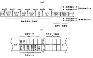
- the transmission procedure is one frame cycle following the control / monitoring data area and the management data area between the start signal ST of the transmission signal and the next start signal ST.
- the start signal ST is longer than the time width of the transmission data signal and has a potential level higher than the threshold value Vst (18 V in this embodiment) of the transmission clock signal.
- the transmission data signal has a potential level area higher than the transmission clock signal threshold Vst (corresponding to the transmission clock signal, +24 V in this embodiment) and a potential level area lower than the transmission clock signal threshold Vst. Consists of.
- the potential level area higher than the threshold Vst of the transmission clock signal is the latter half of one cycle, and the potential level area lower than the threshold Vst of the transmission clock signal is the first half of one cycle. There is no limitation, and the order may be reversed.
- the pulse width of the potential level area lower than the threshold value Vst represents the data of the control signal.
- the pulse width of the potential level area lower than the threshold value Vst constitutes a control data area as control data, and the control data area corresponds to the upper stage of the control / monitoring data area in FIG. .
- the pulse width (3/4) t0 of the transmission clock signal represents the logical data “0”, and the pulse width (1/4) t0 is the logical data “0”. 1 ".
- the length is not limited and may be determined appropriately.
- the data of the monitoring signal is represented by whether the current superimposed on the potential level area lower than the threshold value Vst is larger or smaller than a predetermined value.
- the current value superimposed in the potential level area lower than the threshold value Vst constitutes a monitoring data area as monitoring data, and the monitoring data area is the control / monitoring data area in FIGS. 4 (a) and 4 (b). It corresponds to the lower row.
- a current signal smaller than 10 mA represents logical data “0”, and a current signal larger than 10 mA represents logical data “1”.
- each of the slave stations 4 generates an internal circuit power supply from a transmission clock signal.
- the power supply of the motor 5 arranged in each zone is obtained from the common power supply lines P and N different from the common data signal lines DP and DN.
- control data for each slave station 4 is composed of operation permission data (RE) of the motor 5 and download data (DL) as shown in FIG. 4 (b).
- RE operation permission data
- DL download data
- the size (number of bits) of each data is not considered.
- the operation permission data (RE) is transmitted when the operation of the motor 5 is permitted to the slave station 4 arranged in the zone on the route for conveying the article.
- Download data is output when the no-load normal torque value MS0 and the allowable maximum torque value stored in the initial set value storage means 52 of the slave station input / output unit 40 described later are set on the master station 2 side. Is done.
- the monitoring data for each slave station 4 includes the presence / absence data (SLn) corresponding to the presence detection signal of the presence sensor 6 and an abnormality indicating that the zone operation is abnormal. It consists of data (abnormal 1, abnormal 2, abnormal 3, abnormal 4) and normal data (normal) indicating that the drive system is operating normally.
- a management data area is provided as shown in FIGS. 4 (a) and 4 (b).
- the upper part is an area where data is output from the master station 2 (hereinafter referred to as a management control data area), and the lower part is data is input to the master station 2.
- An area (hereinafter referred to as a management monitoring data area) is shown.
- the first management control data ISTo for instructing the slave station 4 to request information and the second management control data IDXo for specifying the slave station address are superimposed from the master station 2. Is done. Further, the first management monitoring data STi and the second management monitoring data IDXi corresponding to the first management control data ISTo from the slave station 4 specified by the second management control data IDXo are superimposed on the management monitoring data area.
- the master station input unit 25 includes monitoring signal detection means 35 and monitoring data extraction means 36.
- the monitoring signal detection means 35 detects the monitoring signal superimposed on the common data signal lines DP and DN from the slave station 4.
- the monitoring signal data (SLn data, abnormality 1 data, abnormality 2 data, abnormality 3 data, abnormality 4 data, and normal data) has a current superimposed on a potential level lower than the threshold value Vst greater than 10 mA.
- the monitor signal is received from each of the slave stations 4 after the start signal ST is transmitted. Then, the monitoring signal detected by the monitoring signal detection unit 35 is delivered to the monitoring data extraction unit 36.
- the monitoring data extraction unit 36 extracts monitoring data (SLn data, abnormality 1 data, abnormality 2 data, abnormality 3 data, abnormality 4 data, normal data) and management monitoring data in synchronization with the timing from the timing generation unit 32. Then, it is sent to the input data unit 26 as serial input data.
- monitoring data Sn data, abnormality 1 data, abnormality 2 data, abnormality 3 data, abnormality 4 data, normal data
- management monitoring data in synchronization with the timing from the timing generation unit 32. Then, it is sent to the input data unit 26 as serial input data.
- IDX table creation process when a response from the slave station 4 is extracted for the address designated by the master station 2, the response is delivered to the management data unit 22. Receiving this, the management data unit 22 stores the head address at that time in the storage unit 29 as data of the IDX table, as described above.
- the input data unit 26 converts the serial input data received from the monitoring data extracting means 36 into parallel data, and sends it to the input / output unit 12 of the control unit 1 as monitoring data and management monitoring data.
- the slave station 4 includes a slave station input / output unit 40, a slave station line receiver 53, a slave station line driver 54, motor drive means 55, torque detection means 60, and an initial setting switch SWn.
- the motor driving means 55 receives power from the DC power supply 8 provided outside the slave station 4 via the common power supply lines P and N, and outputs an output signal from the operation means 47 of the slave station input / output unit 40 described later. Based on the above, the motor 5 is driven or stopped.
- the torque detection means 60 includes a small resistance r inserted in series between the input terminals of the common power supply lines P and N and the motor driving means 55, and a small resistance when the motor current I flows through the small resistance r.
- the current torque value of the motor 5 is obtained from the analog DC voltage signal generated at both ends of r.
- the small resistance r may be any as long as it does not affect the operation of the motor 5, and a clamp-type current sensor may be used instead of the small resistance r.
- the analog DC voltage signal generated at both ends of the small resistor r is amplified by the amplifier 61 and converted into a digital signal by the A / D converter 62. Then, the current / torque conversion means 63 converts the value of the digital signal Id input from the A / D conversion means 62 into a torque data value according to the I / T conversion coefficient K.
- the torque data value (current torque value) obtained by the current / torque conversion means 63 is delivered to the comparison means 49 and the initial set value storage means 52 of the slave station input / output unit 40 described later.
- the slave station input / output unit 40 includes a transmission receiving means 41, an address extracting means 42, a local address setting means 43, a local zone control data extracting means 44, a previous zone monitoring data extracting means 45, a monitoring data. It has a transmission means 46, an operation means 47, a stable time detection means 48, a comparison means 49, an input means 50, an initial set value instruction means 51, and an initial set value storage means 52.
- the slave station 4 of this embodiment includes an MCU that is a microcomputer control unit as an internal circuit, and this MCU functions as the slave station input / output unit 40.
- the transmission reception means 41 receives the transmission signal transmitted to the common data signal lines DP and DN via the slave station line receiver 53 and delivers it to the address extraction means 42.
- the address extracting means 42 counts transmission signal pulses starting from a start signal ST indicating the start of the transmission data signal. Then, at the timing when the count value coincides with the own station address data set by the own station address setting means 43, the transmission reception signal is delivered to the own zone control data extracting means 44 and the monitoring data transmitting means 46 is made effective. .
- the address extraction means 42 also delivers the transmission reception signal to the previous zone monitoring data extraction means 45 at a timing that matches the address data of the slave station 4 arranged in the previous zone, which is obtained based on the local station address data.
- the monitoring data transmission means 46 When the monitoring data transmission means 46 is validated by the address extraction means 42, the presence / absence data (SLn), abnormality 1 data, abnormality 2 data, abnormality 3 data, abnormality 4 data delivered from the input means 50, Alternatively, normal data is output as a monitoring signal to the common data signal lines DP and DN via the slave station line driver 54. The monitoring signal is superimposed on the monitoring data area of the transmission procedure.
- the own zone control data extraction means 44 extracts control data from the transmission reception signal delivered from the address extraction means 42. If the extracted control data permits the operation of the motor 5 in the own zone, an ON signal is output to the operating means 47.
- the previous zone monitoring data extracting unit 45 extracts monitoring data related to detection of the stock sensor 6 in the previous zone from the transmission reception signal delivered from the address extracting unit 42.
- the extracted monitoring data is data indicating the presence of a transported object
- an ON signal is output to the operating means 47 and the stable time detecting means 48.
- the operation zone 47 When the operation means 47 receives the ON signal from the previous zone monitoring data extraction means 45 or the detection signal indicating that there is a transported object from the stock sensor 6 via the input means 50, the operation zone 47 has its own zone control data. When an ON signal is received from the extraction means 44, a drive instruction is output to the motor drive means 55.
- the stable time detecting means 48 measures the elapsed time from the timing of receiving the ON signal from the previous zone monitoring data extracting means 45, and after the preset stable time ton has elapsed, the first valid signal is compared with the comparing means. 49.
- the stable time detecting means 48 also measures the elapsed time from the timing when the detection signal indicating that there is a conveyed object is received from the in-stock sensor 6 via the input means 50, and the preset stable time ton is After elapses, the second valid signal is output to the comparison means 49.
- the comparison means 49 receives the first valid signal from the stable time detection means 48. Then, the comparison is performed between the data (current torque value) delivered from the current / torque conversion means 63 and the no-load normal torque value MS0 delivered from the initial set value storage means 52.
- the current torque value is a value in the allowable torque range including the no-load normal torque value MS0 (a range obtained by adding or subtracting a predetermined percentage k% tolerance to the no-load normal torque value MS0) (m0 shown in FIG. 6).
- the data indicating normality is delivered to the input means 50.
- the timer TM1 (first valid signal) in the stable time detecting means 48 is turned “ON”, the stock detection signal is “no stock”, and the current torque value. Is determined to be “normal” with the AND condition being m0 included in the allowable torque range.
- abnormal data 1 abnormal data 1 indicating that the device life of the motor 5 is approaching is delivered to the input means 50.
- the timer TM1 (first effective signal) in the stable time detecting means 48 is “ON”, the presence detection signal of the own zone is “no arrival”, and An “abnormal 1” determination is made based on an AND condition that the current torque value is m0h, which is larger than the no-load allowable maximum torque value.
- abnormal data 2 indicating idling of the roller 7 or slip of the belt is handed over to the input means 50.
- the timer TM1 (first effective signal) in the stable time detecting means 48 is “ON”, the presence detection signal of the own zone is “no arrival”, and An “abnormal 2” determination is made on the basis of an AND condition that the current torque value is m0l smaller than the no-load allowable minimum torque value.
- the current torque value in the no-load stable state is smaller than the maximum allowable torque value at no load (the normal torque value at no load plus a predetermined percentage k% tolerance) (in the case of m0l shown in FIG. 6). ) Means that the roller 7 is idling or the belt is slipping.
- the comparison means 49 further indicates that the presence detection signal received from the arrival sensor 6 via the input means 50 indicates that there is a transported object (there is presence of goods), and then the stabilization time detection means 48 to the second time.
- the data (current torque value) delivered from the current / torque conversion means 63 is compared with the allowable maximum torque value delivered from the initial set value storage means 52.
- abnormal data 3 abnormal data 3 indicating that the load weight is excessive (overweight). To hand over.
- the timer TM2 (second effective signal) in the stable time detecting means 48 is “ON”, the presence detection signal of the own zone is “present presence”, and An “abnormality 3” determination is made on the basis of an AND condition that the current torque value is n0h which is larger than the allowable maximum torque value NS0 + j%.
- the input unit 50 delivers the normal data, abnormal data 1, abnormal data 2, and abnormal data 3 delivered from the comparison unit 49 to the monitoring data transmission unit 46. Further, the presence / absence data (SLn) is delivered to the monitoring data transmission means 46 based on the contents of the presence detection signal input from the presence sensor 6. Further, when receiving an abnormality detection signal output from the thermo protector 9 when the motor 5 is in a high temperature state, the abnormality data 4 is delivered to the monitoring data transmission means 46.
- the data delivered to the monitoring data transmitting means 46 is superimposed on the monitoring data area of the transmission procedure as a monitoring signal as described above.
- the abnormality detection signal output from the thermo protector 9 is also input to the motor driving means 55. Upon receiving the abnormality detection signal, the motor driving means 55 causes the motor 5 to stop urgently.
- the initial setting switch SWn is used when the comparison means 49 sets a normal torque value used for comparison determination processing. Since it is clear that the drive system is normal before the start of use of the system, after replacement of the motor 5, or after replacement of the belt, the torque value at that time is a normal torque value. Therefore, when the current torque value when it is clear that the current torque value becomes the normal torque value is set as the normal torque value, the initial setting switch SWn is set to “ON”.
- the initial setting value instruction means 51 When the initial setting switch SWn is set to “ON”, the initial setting value instruction means 51 outputs an ON signal to the initial setting value storage means 52.
- the initial set value storage means 52 When the stock detection signal received from the stock sensor 6 via the input means 50 is the initial set value storage means 52 indicating that there is no transported object (no stock), the initial set value storage means 52 When the ON signal is received, the current torque value delivered from the torque detection means 60 is stored as a normal torque value MS0 at no load.
- an ON signal from the initial setting value instruction means 51 is received.
- a value obtained by adding a tolerance of a predetermined ratio j% to the current torque value delivered from the torque detection means 60 is stored as an allowable maximum torque value WS0 + j%.
- the timing when the initial setting switch SWn is set to “ON” is when an article having a standard weight is placed on the conveyance path of the own zone. The user decides that the item is a standard weight.
- the initial set value storage means 52 When the ON signal is not received from the initial set value instruction means 51, that is, the initial set value storage means 52 during normal operation is a case where the stock detection signal indicates that there is no conveyed product (no stock).
- the normal torque value MS0 at no load is transferred to the comparison means 49 when the load detection signal indicates that a load is present (the load is present).
- the initial setting of the no-load normal torque value MS0 and the allowable maximum torque value WS0 + j% may be performed via the master station 2.
- the no-load normal torque value MS0 and the allowable maximum torque value WS0 + j% As described above, the download data is transmitted using the control data area.
- the slave station input / output unit 40 extracts its own zone DL data indicated by an imaginary line in FIG. Means 56 shall be provided.
- the own zone DL data extracting unit 56 receives and transmits from the address extracting unit 42 in the same manner as the own zone control data extracting unit 44 at the same timing as the own zone control data extracting unit 44 receives the transmission reception signal from the address extracting unit 42. Receive a signal.
- the no-load normal torque value MS0 and the allowable maximum torque value WS0 + j% are extracted from the transmission reception signal and delivered to the initial set value storage means 52 by a predetermined procedure.
- the no-load normal torque value MS0 and the allowable maximum torque value WS0 + j% delivered from the own zone DL data extraction means 56 to the initial setting value storage means 52 are the same as those set via the initial setting switch SWn.
- the set value storage means 52 delivers the comparison value to the comparison means 49.
- the setting by the initial setting switch SWn and the download from the master station 2 may be used together.
- initial setting is performed via the initial setting switch SWn in an arbitrary zone, and the normal torque value MS0 at no load and the allowable maximum torque value WS0 + j% set there are uploaded via the master station 2. Then, the uploaded data is stored in the storage unit of the control unit 1 and transmitted to each of the slave stations 4 in the same zone of the specification via the master station 2.
- the master station 2 When there are many zones of the same specification with the same configuration of the motor 5 and the roller 7, it is possible to reduce labor and time required for the setting work, compared to the case where setting values are set for all the zones. .
- the normal torque value MS0 at no load and the allowable maximum torque value WS0 + j% set via the initial setting switch SWn are uploaded via the master station 2 each time, and these individual data are controlled.
- the data may be stored in the storage unit of the unit 1, and these data may be collectively transmitted to each of the slave stations 4 via the master station 2 when the system is activated.
- the master station 2 and the plurality of slave stations 4 are connected by the common data signal lines DP and DN.
- the connection method is not limited as long as data signals can be transmitted and received.
- wireless connection may be used.
Landscapes
- Control Of Conveyors (AREA)
Abstract
L'invention concerne un système de transport avec un trajet de transport divisé en une pluralité de zones disposées de manière à être côte à côte dans la direction de transport. Chaque zone est équipée des éléments suivants : un moyen d'entraînement pour le trajet de transport ; un capteur de stock qui détecte la présence d'un objet transporté ; un moyen de détection permettant d'obtenir un signal électrique qui change en fonction du couple de sortie du moyen d'entraînement ; et un moyen de traitement de calcul permettant d'effectuer un calcul de comparaison entre une valeur de consigne prédéterminée et une valeur calculée obtenue en fonction de la valeur du signal électrique. Le moyen de traitement de calcul acquiert des informations auprès du capteur de stock situé dans la zone précédente du côté amont de la zone donnée dans lequel ledit moyen de traitement de calcul est situé. Lorsqu'un objet devant être transporté entre dans la zone précédente, le moyen d'entraînement situé dans la zone donnée est mis en fonctionnement. Lorsqu'il y a du stock dans la zone précédente mais pas dans la zone donnée, le calcul de comparaison est utilisé pour déterminer la présence d'une anomalie dans le système d'entraînement. Lorsqu'il y a du stock dans la zone précédente et dans la zone donnée, le calcul de comparaison est utilisé pour déterminer la présence d'un excès de poids.
Priority Applications (2)
| Application Number | Priority Date | Filing Date | Title |
|---|---|---|---|
| PCT/JP2015/057492 WO2016147254A1 (fr) | 2015-03-13 | 2015-03-13 | Système de transport |
| JP2017505769A JP6211230B2 (ja) | 2015-03-13 | 2015-03-13 | 搬送システム |
Applications Claiming Priority (1)
| Application Number | Priority Date | Filing Date | Title |
|---|---|---|---|
| PCT/JP2015/057492 WO2016147254A1 (fr) | 2015-03-13 | 2015-03-13 | Système de transport |
Publications (1)
| Publication Number | Publication Date |
|---|---|
| WO2016147254A1 true WO2016147254A1 (fr) | 2016-09-22 |
Family
ID=56918711
Family Applications (1)
| Application Number | Title | Priority Date | Filing Date |
|---|---|---|---|
| PCT/JP2015/057492 Ceased WO2016147254A1 (fr) | 2015-03-13 | 2015-03-13 | Système de transport |
Country Status (2)
| Country | Link |
|---|---|
| JP (1) | JP6211230B2 (fr) |
| WO (1) | WO2016147254A1 (fr) |
Cited By (3)
| Publication number | Priority date | Publication date | Assignee | Title |
|---|---|---|---|---|
| WO2020203476A1 (fr) * | 2019-04-05 | 2020-10-08 | 伊東電機株式会社 | Système transporteur, dispositif de diagnostic d'anomalie, programme de diagnostic d'anomalie et support d'enregistrement lisible par ordinateur sur lequel un programme de diagnostic d'anomalie a été enregistré |
| EP3812861A1 (fr) * | 2019-10-25 | 2021-04-28 | Itoh Denki Co., Ltd. | Système de convoyeur |
| JP2021121562A (ja) * | 2020-01-31 | 2021-08-26 | 三菱パワー株式会社 | 供給システムの制御装置、これを備える供給システム、及びその制御方法並びに制御プログラム |
Citations (3)
| Publication number | Priority date | Publication date | Assignee | Title |
|---|---|---|---|---|
| JP2003292140A (ja) * | 2002-03-29 | 2003-10-15 | Okura Yusoki Co Ltd | コンベヤ装置 |
| JP2009286597A (ja) * | 2008-05-30 | 2009-12-10 | Ito Denki Kk | コンベア装置 |
| JP2013199359A (ja) * | 2012-03-26 | 2013-10-03 | Ito Denki Kk | コンベア装置、並びに、ゾーンコントローラ |
Family Cites Families (1)
| Publication number | Priority date | Publication date | Assignee | Title |
|---|---|---|---|---|
| US8887897B2 (en) * | 2010-08-31 | 2014-11-18 | Itoh Denki Co., Ltd. | Fault diagnosis method for roller conveyor, roller conveyor, and controller for conveyor |
-
2015
- 2015-03-13 WO PCT/JP2015/057492 patent/WO2016147254A1/fr not_active Ceased
- 2015-03-13 JP JP2017505769A patent/JP6211230B2/ja active Active
Patent Citations (3)
| Publication number | Priority date | Publication date | Assignee | Title |
|---|---|---|---|---|
| JP2003292140A (ja) * | 2002-03-29 | 2003-10-15 | Okura Yusoki Co Ltd | コンベヤ装置 |
| JP2009286597A (ja) * | 2008-05-30 | 2009-12-10 | Ito Denki Kk | コンベア装置 |
| JP2013199359A (ja) * | 2012-03-26 | 2013-10-03 | Ito Denki Kk | コンベア装置、並びに、ゾーンコントローラ |
Cited By (4)
| Publication number | Priority date | Publication date | Assignee | Title |
|---|---|---|---|---|
| WO2020203476A1 (fr) * | 2019-04-05 | 2020-10-08 | 伊東電機株式会社 | Système transporteur, dispositif de diagnostic d'anomalie, programme de diagnostic d'anomalie et support d'enregistrement lisible par ordinateur sur lequel un programme de diagnostic d'anomalie a été enregistré |
| EP3812861A1 (fr) * | 2019-10-25 | 2021-04-28 | Itoh Denki Co., Ltd. | Système de convoyeur |
| JP2021121562A (ja) * | 2020-01-31 | 2021-08-26 | 三菱パワー株式会社 | 供給システムの制御装置、これを備える供給システム、及びその制御方法並びに制御プログラム |
| JP7504604B2 (ja) | 2020-01-31 | 2024-06-24 | 三菱重工業株式会社 | 供給システムの制御装置、これを備える供給システム、及びその制御方法並びに制御プログラム |
Also Published As
| Publication number | Publication date |
|---|---|
| JPWO2016147254A1 (ja) | 2017-11-30 |
| JP6211230B2 (ja) | 2017-10-11 |
Similar Documents
| Publication | Publication Date | Title |
|---|---|---|
| CN105189318B (zh) | 辊式输送装置、控制器和机械装置的异常检测方法 | |
| US8887897B2 (en) | Fault diagnosis method for roller conveyor, roller conveyor, and controller for conveyor | |
| US9446907B2 (en) | Zone controller and conveyor device | |
| JP6211230B2 (ja) | 搬送システム | |
| JP4979658B2 (ja) | 搬送制御システム及び搬送制御方法 | |
| JPWO2003002436A1 (ja) | ゾーンコントローラ | |
| US11420825B2 (en) | Method for monitoring the state of a conveyor system, and control unit, motorized roller, and conveyor system for carrying out the method | |
| JP2013199359A (ja) | コンベア装置、並びに、ゾーンコントローラ | |
| WO2017037774A1 (fr) | Système de transport | |
| JP2019189386A (ja) | 制御装置及びコンベヤ | |
| WO2014147705A1 (fr) | Système de transmission de signal de contrôle/supervision | |
| JP2018177441A (ja) | ローラコンベア装置 | |
| TWI608321B (zh) | 控制裝置 | |
| KR20110016785A (ko) | 컨베이어 장치 및 그에 따른 컨베이어 시스템 | |
| JP6943064B2 (ja) | 制御装置、制御システム、方法及びプログラム | |
| JP5456999B2 (ja) | ベルト支持ローラモニタリングシステム | |
| JP5120994B1 (ja) | 伝送クロック信号異常検出方式、およびその方式に使用する子局ターミナル | |
| JP5388941B2 (ja) | 制御・監視信号伝送システムにおける始動制御方式 | |
| CN105984796A (zh) | 乘客输送装置 | |
| JP5882810B2 (ja) | 搬送装置、並びに、物品保管装置 | |
| JP2002240926A (ja) | ローラーコンベア及びローラーコンベアの制御方法 | |
| CN120523122A (zh) | 驱动控制器、输送系统及输送控制方法 | |
| JP2005306591A (ja) | 搬送システム | |
| JP6655768B2 (ja) | 制御・監視信号伝送システム | |
| NL1042791B1 (en) | Control device for conveying system |
Legal Events
| Date | Code | Title | Description |
|---|---|---|---|
| 121 | Ep: the epo has been informed by wipo that ep was designated in this application |
Ref document number: 15885352 Country of ref document: EP Kind code of ref document: A1 |
|
| ENP | Entry into the national phase |
Ref document number: 2017505769 Country of ref document: JP Kind code of ref document: A |
|
| NENP | Non-entry into the national phase |
Ref country code: DE |
|
| 122 | Ep: pct application non-entry in european phase |
Ref document number: 15885352 Country of ref document: EP Kind code of ref document: A1 |