WO2016147281A1 - Système de stockage réparti et procédé de commande pour système de stockage réparti - Google Patents
Système de stockage réparti et procédé de commande pour système de stockage réparti Download PDFInfo
- Publication number
- WO2016147281A1 WO2016147281A1 PCT/JP2015/057615 JP2015057615W WO2016147281A1 WO 2016147281 A1 WO2016147281 A1 WO 2016147281A1 JP 2015057615 W JP2015057615 W JP 2015057615W WO 2016147281 A1 WO2016147281 A1 WO 2016147281A1
- Authority
- WO
- WIPO (PCT)
- Prior art keywords
- node
- virtual
- data
- deduplication
- logical
- Prior art date
- Legal status (The legal status is an assumption and is not a legal conclusion. Google has not performed a legal analysis and makes no representation as to the accuracy of the status listed.)
- Ceased
Links
Images








Classifications
-
- G—PHYSICS
- G06—COMPUTING OR CALCULATING; COUNTING
- G06F—ELECTRIC DIGITAL DATA PROCESSING
- G06F3/00—Input arrangements for transferring data to be processed into a form capable of being handled by the computer; Output arrangements for transferring data from processing unit to output unit, e.g. interface arrangements
- G06F3/06—Digital input from, or digital output to, record carriers, e.g. RAID, emulated record carriers or networked record carriers
- G06F3/0601—Interfaces specially adapted for storage systems
- G06F3/0628—Interfaces specially adapted for storage systems making use of a particular technique
- G06F3/0638—Organizing or formatting or addressing of data
- G06F3/064—Management of blocks
- G06F3/0641—De-duplication techniques
-
- G—PHYSICS
- G06—COMPUTING OR CALCULATING; COUNTING
- G06F—ELECTRIC DIGITAL DATA PROCESSING
- G06F12/00—Accessing, addressing or allocating within memory systems or architectures
- G06F12/02—Addressing or allocation; Relocation
- G06F12/08—Addressing or allocation; Relocation in hierarchically structured memory systems, e.g. virtual memory systems
- G06F12/10—Address translation
-
- G—PHYSICS
- G06—COMPUTING OR CALCULATING; COUNTING
- G06F—ELECTRIC DIGITAL DATA PROCESSING
- G06F3/00—Input arrangements for transferring data to be processed into a form capable of being handled by the computer; Output arrangements for transferring data from processing unit to output unit, e.g. interface arrangements
- G06F3/06—Digital input from, or digital output to, record carriers, e.g. RAID, emulated record carriers or networked record carriers
-
- G—PHYSICS
- G06—COMPUTING OR CALCULATING; COUNTING
- G06F—ELECTRIC DIGITAL DATA PROCESSING
- G06F3/00—Input arrangements for transferring data to be processed into a form capable of being handled by the computer; Output arrangements for transferring data from processing unit to output unit, e.g. interface arrangements
- G06F3/06—Digital input from, or digital output to, record carriers, e.g. RAID, emulated record carriers or networked record carriers
- G06F3/0601—Interfaces specially adapted for storage systems
- G06F3/0602—Interfaces specially adapted for storage systems specifically adapted to achieve a particular effect
- G06F3/0608—Saving storage space on storage systems
-
- G—PHYSICS
- G06—COMPUTING OR CALCULATING; COUNTING
- G06F—ELECTRIC DIGITAL DATA PROCESSING
- G06F3/00—Input arrangements for transferring data to be processed into a form capable of being handled by the computer; Output arrangements for transferring data from processing unit to output unit, e.g. interface arrangements
- G06F3/06—Digital input from, or digital output to, record carriers, e.g. RAID, emulated record carriers or networked record carriers
- G06F3/0601—Interfaces specially adapted for storage systems
- G06F3/0602—Interfaces specially adapted for storage systems specifically adapted to achieve a particular effect
- G06F3/061—Improving I/O performance
-
- G—PHYSICS
- G06—COMPUTING OR CALCULATING; COUNTING
- G06F—ELECTRIC DIGITAL DATA PROCESSING
- G06F3/00—Input arrangements for transferring data to be processed into a form capable of being handled by the computer; Output arrangements for transferring data from processing unit to output unit, e.g. interface arrangements
- G06F3/06—Digital input from, or digital output to, record carriers, e.g. RAID, emulated record carriers or networked record carriers
- G06F3/0601—Interfaces specially adapted for storage systems
- G06F3/0628—Interfaces specially adapted for storage systems making use of a particular technique
- G06F3/0662—Virtualisation aspects
- G06F3/0665—Virtualisation aspects at area level, e.g. provisioning of virtual or logical volumes
-
- G—PHYSICS
- G06—COMPUTING OR CALCULATING; COUNTING
- G06F—ELECTRIC DIGITAL DATA PROCESSING
- G06F3/00—Input arrangements for transferring data to be processed into a form capable of being handled by the computer; Output arrangements for transferring data from processing unit to output unit, e.g. interface arrangements
- G06F3/06—Digital input from, or digital output to, record carriers, e.g. RAID, emulated record carriers or networked record carriers
- G06F3/0601—Interfaces specially adapted for storage systems
- G06F3/0668—Interfaces specially adapted for storage systems adopting a particular infrastructure
- G06F3/067—Distributed or networked storage systems, e.g. storage area networks [SAN], network attached storage [NAS]
-
- G—PHYSICS
- G06—COMPUTING OR CALCULATING; COUNTING
- G06F—ELECTRIC DIGITAL DATA PROCESSING
- G06F2212/00—Indexing scheme relating to accessing, addressing or allocation within memory systems or architectures
- G06F2212/10—Providing a specific technical effect
- G06F2212/1041—Resource optimization
- G06F2212/1044—Space efficiency improvement
-
- G—PHYSICS
- G06—COMPUTING OR CALCULATING; COUNTING
- G06F—ELECTRIC DIGITAL DATA PROCESSING
- G06F2212/00—Indexing scheme relating to accessing, addressing or allocation within memory systems or architectures
- G06F2212/15—Use in a specific computing environment
- G06F2212/152—Virtualized environment, e.g. logically partitioned system
-
- G—PHYSICS
- G06—COMPUTING OR CALCULATING; COUNTING
- G06F—ELECTRIC DIGITAL DATA PROCESSING
- G06F2212/00—Indexing scheme relating to accessing, addressing or allocation within memory systems or architectures
- G06F2212/15—Use in a specific computing environment
- G06F2212/154—Networked environment
Definitions
- the present invention relates to a distributed storage system.
- Patent Document 1 when each distributed server configuring a distributed network receives a read request for data stored in another distributed server from a client, the distributed server acquires data from the other server and responds to the client.
- the deduplication management apparatus manages a database of unique IDs that identify data such as hash values in the data stored in each distributed server.
- the deduplication management apparatus searches the database, and when there are a number of data associated with the same unique ID equal to or greater than the threshold, selects a distributed server from which data is to be deleted, and selects the duplicate data stored in the selected distributed server. Deduplication is performed by deleting.
- the distributed storage system has a plurality of nodes which are connected to each other and each controls storage of data in a logical storage area configured from a storage medium.
- the plurality of nodes provide a virtual storage area across the logical storage area controlled by each of the host devices, and a plurality of virtual partial areas obtained by dividing the virtual storage area and a plurality of partial logical storage areas obtained by dividing the logical storage area
- the allocation is managed, and the data written in the virtual storage area is distributed by a plurality of nodes and stored in the logical storage area.
- the first node out of the plurality of nodes has the same data as the first data written in the first virtual partial area managed by the first node out of the plurality of virtual partial areas.
- the inter-node deduplication is executed to change the assignment of one of the virtual partial areas to the other logical partial area.
- the first node is a virtual partial area divided from the virtual storage area.
- Cross-node deduplication is performed across the second virtual partial area managed by the first node.
- An outline of a method for determining whether or not to perform deduplication across nodes is shown.
- An example of a system configuration of a distributed storage system is shown. Indicates information for controlling the distributed storage system.
- the structural example of a virtual volume management table is shown.
- the structural example of a pool volume management table is shown.
- the structural example of a drive management table is shown.
- the structural example of a page mapping table is shown.
- the structural example of a page load frequency table is shown.
- the structural example of a virtual chunk load frequency table is shown.
- the structural example of a logical chunk load frequency table is shown.
- the structural example of a Fingerprint Table (FPT) is shown.
- the structural example of a FPT update log is shown.
- the structural example of a deduplication effect management table is shown.
- the structural example of a deduplication log structured mapping table is shown.
- region control table is shown.
- 2 shows a flowchart of read processing of a distributed storage system.
- 6 shows a flowchart of synchronous write processing.
- the flowchart of a back end write process is shown.
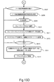
- the flowchart of a deduplication process is shown.
- the flowchart of a node deduplication process is shown.
- the flowchart of a node crossing deduplication process is shown.
- the continuation of the flowchart of the cross-node deduplication processing is shown.
- the flowchart of a node crossing deduplication cancellation process is shown.
- This embodiment discloses a distributed storage system that can realize deduplication.
- the distributed storage system is configured by connecting a plurality of computer nodes each including a storage device via a network.
- the distributed storage system realizes a virtual storage system that realizes a storage pool (also simply called a pool) by storage devices of a plurality of computer nodes.
- the distributed storage system provides a virtual volume to the host.
- the distributed storage system allocates a logical storage area from a pool (storage pool) to a virtual storage area (storage area provided by a virtual volume) that has been write-accessed.
- One pool is composed of one or a plurality of logical volumes. This logical volume is also called a pool volume.
- the entity of the pool volume is a storage area of the disk drive.
- a storage area of a disk drive of another computer node can be allocated to the pool volume.
- the distributed storage system can deduplicate data stored in the computer node.
- deduplication when there is some data and data containing the same contents as that data (duplicate data), by replacing one data with pointer information that points to the other data, and deleting that one data Therefore, it is possible to save a storage area necessary for storing the data.
- Deduplication can be executed within one computer node, or can be executed across a plurality of computer nodes. The former is called node deduplication, and the latter is called cross-node deduplication.
- the data the substance of the data (called the data) according to the pointer information.
- the data When the data is stored in the computer node that has received the read request, the data is read from the computer node.
- the first computer node if the data is stored in a computer node (referred to as the second computer node) that is different from the computer node that received the read request (referred to as the first computer node), the first computer node It is necessary to transfer the read request to the second computer node and transfer the data from the second computer node to the first computer node via the network. In this way, read processing that requires data communication from the second computer node to the first computer node in order to read the deduplicated data is referred to as read across redundant data nodes.
- the unit of deduplication is a chunk.
- a virtual chunk is a partial storage area obtained by dividing a virtual volume at a fixed length.
- a logical chunk is a partial storage area obtained by dividing a pool volume at a fixed length. The size of the virtual chunk and the logical chunk is equal, and the size of the virtual chunk and the logical chunk is equal to the page size or smaller than the page size.
- mapping between virtual chunks and logical chunks mapping managed by a deduplication mapping table 234 described later
- Node deduplication and cross-node deduplication are realized by updating this mapping.
- a virtual page is a partial storage area obtained by dividing a virtual volume at a fixed length, and any one computer node 101 is associated with the virtual page (however, in the initial state, any computer node is associated with the virtual page. 101 is also not associated).
- the computer node 101 associated with the virtual page has the highest IO frequency to the virtual page according to the IO frequency (also called I / O frequency or access frequency) to the virtual page for each computer node 101.
- the computer node 101 may be changed. In that case, the data (user data) in the virtual page is moved to the computer node 101 of the change destination.
- the mapping between the virtual chunk and the logical chunk described above may need to be updated in accordance with the movement.
- the storage device includes one storage drive such as one HDD or SSD, a RAID device including a plurality of storage drives, and a plurality of RAID devices.
- a stripe or stripe data is a unit that is a source of generation of a redundant code for data protection.
- the stripe is sometimes referred to as user data in order to differentiate it from the redundant code.
- the stripe is stored in a storage device in the computer node and is used in generating redundant codes in other computer nodes.
- a stripe is composed of one or a plurality of logical chunks, and data is made redundant in units of stripes.
- the page size is an integer multiple (1 or more) of the chunk size
- the stripe size is an integer multiple (1 or more) of the page size
- the stripe size is an integral multiple (1 or more) of the chunk size
- the page size is an integer multiple (1 or more) of the stripe size.
- FIG. 1 shows an outline of a method for determining execution of node crossing deduplication according to an example of the present embodiment.
- the computer nodes 101P and 101Q are connected by a network.
- Computer nodes 101R and 101S are also connected by a network.
- the computer node is also simply referred to as a node.
- FIG. 1 is a conceptual diagram illustrating the first determination method.
- the IO load related to the performance of the node such as “network load due to reading across overlapping data nodes”, “average response time”, and “average throughput” for the virtual storage area provided by the virtual volume Based on this information, it is determined whether or not to deduplicate the data stored in the virtual storage area.
- the virtual volume is managed by dividing it into data units such as virtual chunks, which are fixed-length storage areas.
- a data unit may or may not contain duplicate data.
- the IO frequency is recorded for each data unit.
- the graph (a) in FIG. 1 shows a conceptual diagram of the result of summing up the IO frequencies of data units of all computer nodes. Data units are sorted in ascending order with respect to IO frequency. In the first determination method, a data unit on the left side of the data unit threshold P is selected as a candidate for node-overdeduplication. Data units are selected in ascending order with respect to IO frequency. In the cross-node deduplication, duplicate data included in the selected data unit is deduplicated.
- the cross-node deduplication cancellation is performed on the duplicate data included in the data unit on the right side of the data unit threshold P with respect to the duplicate data to which cross-node deduplication is applied.
- the node-to-node deduplication cancellation the node-to-node deduplication is canceled, that is, the state before the node-to-node deduplication is performed on the duplicated data is restored.
- the data unit threshold P is estimated on the basis of information on the IO frequency and response time for each data unit, such as “network load due to reads across duplicate data nodes”, “average response time”, and “average throughput”. It is determined by an index representing the IO load of the node and several threshold values.
- the data unit threshold value P can be set to the minimum value of the data unit threshold values P1, P2, and P3 described below.
- the graph (b) in FIG. 1 is a conceptual diagram of the predicted value (Y1) of the network load due to deduplication node crossing reads.
- the horizontal axis of the graph (b) is the same as that of the graph (a).
- the vertical axis of the graph (b) indicates the predicted value of the network load associated with the redundant data node crossing read that occurs when the node crossing deduplication is executed for the data unit on the left side of X, where X is a certain value on the horizontal axis. .
- a data unit threshold value P1 P1 in FIG.
- the predicted value Y1 is compared with the threshold T1, and in some cases, the inter-node deduplication is not performed for the data unit on the right side of the data unit threshold P1, thereby increasing the network load caused by the execution of the inter-node deduplication. Can be suppressed.
- the graph (c) in FIG. 1 is a conceptual diagram of the predicted value (Y2) of the average response time (average IO response time) of the distributed storage system.
- the horizontal axis of the graph (c) is the same as that of the graph (a).
- the vertical axis of the graph (c) indicates a predicted value of the average response time of the distributed storage system when the node-wide deduplication is executed for the data unit on the left side of X, where X is a certain value on the horizontal axis.
- a data unit threshold value P2 P2 in FIG.
- threshold value T2 threshold value T2 in FIG. 1.
- the predicted value Y2 of the average response time is compared with the threshold value T2, and in some cases, the node-based deduplication is not performed for the data unit on the right side of the data unit threshold P2, and this occurs due to the execution of the node-based deduplication. Longer average response time can be suppressed.
- the graph (d) in FIG. 1 is a conceptual diagram of the predicted value (Y3) of the average throughput of the distributed storage system.
- the horizontal axis of the graph (d) is the same as that of the graph (a).
- the vertical axis of the graph (d) indicates a predicted value of the average throughput of the distributed storage system in the case where cross-node deduplication is executed for the data unit on the left side of X, where X is a certain value on the horizontal axis.
- the data unit threshold value P3 P3 in FIG.
- threshold value T3 threshold value T3 in FIG. 1.
- the average throughput predicted value Y3 is compared with the threshold T3, and in some cases, the node-by-node deduplication is not performed on the data unit on the right side of the data unit threshold P3. Can be suppressed.
- the IO load predicted based on the IO frequency and response time for each data unit (“network load due to reads across duplicate data nodes”, “average response time”, and Based on “average throughput”) and several thresholds, it is possible to determine whether or not to perform deduplication across nodes.
- cross-node deduplication is performed on duplicate data included in a data unit having a small impact on the IO load, and for duplicate data contained in a data unit having a large impact on the IO load.
- Cross-node deduplication is not executed, and distributed storage systems can be controlled so that deduplication cancellation across nodes is executed for duplicate data contained in data units that have a large impact on IO load It becomes.
- FIG. 1 is a conceptual diagram for explaining the second determination method. “Determination method for execution of deduplication across nodes (2)” in FIG.
- the second determination method it is determined whether or not data stored in the virtual storage area is to be deduplicated based on the relative data amount reduction effect of deduplication across nodes.
- the computer nodes 101R and 101S store nine pieces of duplicate data d for each data unit (99A to 99H and 99I to 99Q).
- Duplicate data d (99A to 99G) and duplicate data d (99I to 99P) have already been deduplicated by node deduplication.
- One of the duplicate data d (99H, 99Q) can be deduplicated by deduplication across nodes.
- r is defined as “the number of reductions due to node deduplication”.
- Judgment formula r ⁇ “threshold of judgment formula”
- the amount of data is reduced by a factor of (r + 2) by executing de-duplication across nodes, compared to the case where de-duplication is not performed at all.
- the smaller the value of r in the determination formula the greater the data amount reduction effect of node-to-node deduplication that is about to be executed.
- the possibility of occurrence of duplicated data node crossing reads is reduced, so that there is a high possibility that performance degradation due to node-overlapping deduplication to be executed is reduced.
- the threshold value of the “judgment formula threshold value” is 10
- the value of r is 16.
- the determination result of the expression is False (false).
- it is determined not to execute node-to-node deduplication of duplicate data d (99H, 99Q).
- the second determination method it is possible to select only duplicate data related to cross-node deduplication that has a relatively large data amount reduction effect and little performance degradation as node deduplication candidates.
- the computer node uses one or both of the determination methods (1) and (2) for executing the cross-over node deduplication described above when executing the cross-over node de-duplication. be able to.
- FIG. 2 shows a system configuration example of a distributed storage system.
- the node 101 has, for example, a general server computer configuration.
- the hardware configuration of the node 101 is not particularly limited.
- the node 101 is connected to another node 101 via the network 103 through the port 106.
- the network 103 is configured by, for example, InfiniBand or Ethernet (registered trademark).
- a plurality of nodes 101 form a domain 102.
- the domain 102 may correspond to, for example, a geographical region, or may correspond to the topology of the virtual or physical network 103.
- the network 104 connects a plurality of domains 102. In the following, it is assumed that a domain is associated with a geographically distant site.
- the internal configuration of the node 101 is connected to a port 106, a processor package 111, and a disk drive (hereinafter also referred to as a drive) 113 via an internal network 112.
- the processor package 111 includes a memory 118 and a processor 119.
- the node 101 does not include the disk drive 113. Instead, an external external storage device may be connected to the node 101 and data may be stored therein.
- the memory 118 stores control information necessary for the processor 119 to process read and write commands and execute a storage function, and also stores storage cache data.
- the memory 118 stores a program executed by the processor 119, for example.
- the memory 118 may be a volatile DRAM (Dynamic Random Access Memory) or a non-volatile SCM (Storage Class Memory).
- the drive 113 is, for example, a hard disk drive having an interface such as FC (Fibre Channel), SAS (Serial Attached SCSI), SATA (Serial Advanced Technology Attachment), or an SSD (Solid State) configuration.
- FC Fibre Channel
- SAS Serial Attached SCSI
- SATA Serial Advanced Technology Attachment
- SSD Solid State
- An SCM such as NAND, PRAM (Phase Change Random Access Memory), ReRAM (Resistance Random Access Memory), or a volatile memory may be used.
- the storage device may be made nonvolatile by a battery.
- Each drive group constitutes a RAID.
- Drives, RAIDs, and their collections are storage devices.
- FIG. 3 shows information for controlling the distributed storage system.
- the memory 118 stores various programs including a storage program that implements a storage function, an OS, and an interface program.
- the memory 118 may further store an application program that executes a job.
- the virtual provisioning information 202 includes a page mapping table 215 and a page load frequency table 216.
- the configuration information 203 includes a virtual volume management table 218, a pool volume management table 219, and a drive management table 220.
- the chunk load information 224 is information related to the I / O frequency of the chunk, and includes a virtual chunk load frequency table 225 and a logical chunk load frequency table 226.
- the deduplication management information 229 is information related to the deduplication process, and includes the Fingerprint Table (FPT) 231, the FPT update log 239, the deduplication effect management table 232, the deduplication log structured mapping table 233, and the pool.
- a volume area control table 236 is included.
- a copy of all or part of the information described above may be stored in the drive 113 synchronously or asynchronously.
- the node 101 may hold the above information for each pool, for example.
- One pool is composed of one or a plurality of logical volumes. This logical volume is also called a pool volume.
- the entity of the pool volume is a storage area of the drive 113.
- a storage area of a drive of another node 101 can be allocated to the pool volume.
- each table indicating information held by the node 101
- blank cells are cells from which data is omitted.
- “0x” indicates a hexadecimal number.
- the drive number is unique within the node, and the node number is unique within the system.
- the site number is unique within the system. Note that the node number may be unique within the site.
- FIG. 4A to 4C show configuration examples of tables indicating information included in the configuration information 203.
- FIG. 4A to 4C show management information of different storage resource types.
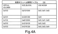
- FIG. 4A shows a configuration example of the virtual volume management table 218.
- the virtual volume management table 218 indicates virtual volume information.
- the virtual volume management table 218 indicates information on a virtual volume provided by the node 101 that holds the information 218.
- the node 101 receives access to the virtual volume to be provided.
- the virtual volume management table 218 may hold information on virtual volumes that are not provided by the own node in case of failure.
- one computer node 101 holding the information 218 may provide one virtual volume independently, or a plurality of computer nodes 101 holding the information 218 may provide one virtual volume. Good.
- the virtual volume management table 218 includes an identifier (virtual volume number) for uniquely identifying each virtual volume in the system, a size (capacity) of each virtual volume, and a node number of a node (referred to as an owner node) that provides each virtual volume. Contains a list.
- the size of the virtual volume indicates not the total amount of allocated logical chunks but the virtual capacity (maximum capacity) of the virtual volume.
- FIG. 4B shows a configuration example of the pool volume management table 219.
- the pool volume management table 219 indicates pool volume information.
- the pool volume management table 219 shows information on pool volumes provided by the node 101 that holds the information 219.
- the pool volume management table 219 includes information on an identifier (pool volume number) that uniquely identifies each pool volume in the system, a size (capacity) of each pool volume, and a node number of a node that provides each pool volume.
- FIG. 4C shows a configuration example of the drive management table 220.
- the drive management table 220 indicates a drive assigned to each pool volume.
- the drive management table 220 indicates information of the local drive 113 included in the node 101 that holds the information 220.
- the drive management table 220 includes, for each pool volume, a set of an identifier (pool volume number) that uniquely identifies each pool volume in the system, a drive type (such as an SSD or NL-SAS drive), and a striped drive number. (A set of drive numbers constituting a RAID) and information on the size (capacity) of the drive. When striping is not performed, only one drive is allocated to the pool volume. Note that different areas of one drive can be assigned to different pool volumes.
- FIG. 5A to 5B show information included in the virtual provisioning information 202.
- FIG. FIG. 5A shows a configuration example of the page mapping table 215.
- the page mapping table 215 holds the correspondence between the virtual page of the virtual volume and the computer node 101.
- the page mapping table 215 holds virtual volume information provided by the node 101 that holds the information 215.
- the virtual page is associated with any one computer node 101 (one of the owner nodes of the virtual volume). That is, it can be paraphrased that a virtual page is assigned to any one computer node 101 (owner node).
- the assignment of the computer node 101 to the virtual page is performed when the first write request is made to the virtual page. It is also possible to allow a computer node 101 other than the computer node 101 to which the virtual page is assigned to access the virtual page.
- an operation for associating a virtual page with a computer node may be expressed as “assign a computer node to a virtual page” or “assign a virtual page to a computer node”.
- the page mapping table 215 holds the virtual volume number, the first LBA (Logical Block Address) and address range of the virtual page of the virtual volume, and the node number of the computer node 101 assigned to the virtual page. When the computer node 101 is not assigned to the virtual page, an invalid value is recorded in the node number column of the page mapping table 215.
- LBA Logical Block Address
- FIG. 5B shows a configuration example of the page load frequency table 216.
- the page load frequency table 216 holds a history of I / O frequency (access frequency) for each virtual page and a history of “frequency of read across duplicate data nodes” for each virtual page. Specifically, the virtual volume number, the head LBA and address range of the virtual page of the virtual volume, the access frequency for the area, the “frequency of reading across overlapping data nodes” for the area, and the I / O for the area Of response time.
- the page load frequency table 216 holds virtual volume information provided by the node 101 that holds the table 216. In addition, the page load frequency table 216 holds information on accesses received by the node holding the table 216 from the own node and other nodes.
- the access frequency and response time information may be acquired and managed for each access source node, or may be acquired and managed separately for read access and write access.
- the node 101 may acquire and manage access frequency and response time information by separating sequential and random access, or may acquire and manage access frequency and response time information in a plurality of measurement cycles. .
- the frequency of reads across duplicate data nodes indicates information on the frequency of reads across duplicate data nodes for a virtual page.
- the “frequency of reads across duplicate data nodes” may be acquired and managed for each access source node.
- the duplication data node crossing read is a read from another node with respect to the logical chunk assigned to the virtual page, which is caused by executing the cross node deduplication.
- FIG. 6A to 6B show information included in the chunk load information 224.
- FIG. 6A to 6B show information included in the chunk load information 224.
- FIG. 6A shows a configuration example of the virtual chunk load frequency table 225.
- the virtual chunk load frequency table 225 holds a history of I / O frequency (access frequency) for each virtual chunk and a history of “frequency of read across overlapping data nodes” for each virtual chunk. Specifically, the virtual volume number and head LBA and address range of the virtual chunk of the virtual volume, the access frequency for the area, the “frequency of reads across duplicate data nodes” for the area, and the I / O of the area Holds the response time.
- the virtual chunk load frequency table 225 is the same as the page load frequency table 216 except for the difference that it retains information related to virtual chunks rather than virtual pages, and thus the description thereof is omitted.
- FIG. 6B shows a configuration example of the logical chunk load frequency table 226.
- the logical chunk load frequency table 226 holds a history of I / O frequency (access frequency) for each logical chunk.
- the logical chunk load frequency table 226 is the same table as the virtual chunk load frequency table 225 except that the logical chunk load frequency table 226 is not related to the virtual chunk but information related to the logical chunk.
- FIG. 7A to 7C, 8 and 9 show information included in the deduplication management information 229.
- FIG. 7A to 7C, 8 and 9 show information included in the deduplication management information 229.
- FIG. 7A shows a configuration example of the Fingerprint Table (FPT) 231.
- the FPT 231 is a table used in the deduplication process in FIG. 13A and is an index for efficiently searching for duplicate data.
- the FPT 231 stores a hash value (Fingerprint, FP) of virtual chunk data calculated for each virtual chunk.
- the hash value can be calculated using a well-known hash function such as CRC, SHA1, or MD5.
- the FPT 231 holds (1) FP, (2) virtual volume number, (3) LBA of the virtual volume, and (4) address range. (2) to (4) are information for uniquely identifying the virtual chunk within the system.
- the FPT 231 is also divided into a plurality of partial tables, and each partial table is configured to be held by a plurality of computer nodes 101 included in the distributed storage system. In preparation for the occurrence of a failure, a computer node 101 different from the computer node 101 holding the partial table may hold a copy of the partial table.
- a method of dividing the FPT 231 into a plurality of partial tables for example, (1) When the number of computer nodes 101 holding partial tables is N, an entry including a certain FP value is an FP value% N (% is a remainder).
- the computer node 101 determined based on the value calculated by the operator) calculates the method for realizing the division of the FPT 231 and (2) a computer node 101 having a predetermined range of FP values. In other words, the computer node 101 holds only the entry including the FP value associated with itself, thereby realizing a method of realizing the division of the FPT 231.
- the FPT 231 may be divided according to certain rules other than these methods.
- the FPT 231 may be configured such that one computer node 101 included in the distributed storage system holds information on all virtual chunks in the distributed storage system. In preparation for the occurrence of a failure, another computer node 101 may hold a copy of the FPT 231.
- FIG. 7B shows a configuration example of the FPT update log 239.
- an update operation to the FPT 231 is recorded.
- the update operation to the FPT 231 is registration or deletion of an entry (row) of the FPT 231.
- the FPT update log 239 holds (1) FP, (2) virtual volume number, (3) virtual volume LBA, (4) address range, and (5) operation.
- (2) to (4) are information for uniquely identifying the virtual chunk within the system.
- the operation column (5) is information for designating an update operation to the FPT 231 and stores either a value of “registration” or “deletion”.
- deduplication is broadly divided into node deduplication and node crossing deduplication.
- Cross-node deduplication is either site deduplication that is deduplication across computer nodes 101 in the same site, or geo deduplication that is deduplication across computer nodes 101 in different sites. That is, the deduplication type is any one of (1) node deduplication, (2) site deduplication, and (3) geo deduplication.
- FIG. 7C shows a configuration example of the deduplication effect management table 232.
- the deduplication effect management table 232 is a table for managing how many logical chunks having a certain FP are deduplicated by node deduplication, site deduplication, and geo deduplication in the distributed storage system.
- One of the computer nodes 101 manages this table.
- Other computer nodes 101 may hold a copy of this table.
- the deduplication effect management table 232 holds (1) node number, (2) FP, (3) node deduplication reduction number, (4) site deduplication reduction number, and (5) geo deduplication reduction number.
- (3) (4) and (5) are the virtual chunks included in the virtual page specified from the node number of (1) by the page mapping table 215. This is information indicating how many deduplications have been made by deduplication and geo deduplication.
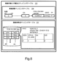
- FIG. 8 shows a configuration example of the deduplication log structured mapping table 233.
- the arrow represents a pointer.
- the deduplication log structured mapping table 233 includes a deduplication mapping table 234 and a deduplication reverse mapping table 235.
- the deduplication mapping table 234 manages the mapping between the virtual chunks in the virtual volume and the logical chunks in the pool volume.
- the computer node 101 can know the storage address (logical address) of the logical chunk mapped to the virtual chunk from the address (LBA) of the virtual volume corresponding to the virtual chunk.
- the deduplication mapping table 234 associates the storage address (LBA) of user data in the virtual volume with the storage address (logical address) of user data in the pool volume.
- the deduplication mapping table 234 manages the mapping between virtual addresses and logical addresses.
- the virtual address is information for uniquely identifying the virtual chunk within the system
- the logical address is information for uniquely identifying the logical chunk within the system. In some cases, no logical chunk is mapped to the virtual chunk.
- the storage address of the virtual volume related to the virtual chunk is specified by the virtual volume number and address (LBA).
- the storage address of the pool volume related to the logical chunk is specified by the pool volume number, the logical address (LBA), and the data length (LEN).
- the deduplication mapping table 234 also records information related to the state related to the virtual chunk.
- the information includes information (“YES” or “NO”) indicating whether or not the virtual chunk has been updated since the execution of the deduplication process in FIG. 13A.
- the initial value of the information is “YES”.
- the FP value calculated when the deduplication process of FIG. 13A is executed is recorded.
- the initial value of “FP” in the deduplication mapping table 234 is an invalid value.
- the site number may be included in the storage address of the pool volume related to the logical chunk. In this case, when the deduplication mapping table 234 is updated, the site number is also set. In the following explanation, there is a case where the site number setting is not clearly shown.
- the distributed storage system of this example stores the data written in the virtual volume in the pool volume using the log structuring method.
- a log structuring method when used, when the computer node 101 updates the data of the virtual chunk with new data, the computer node 101 does not update the data of the corresponding logical chunk with new data. Is added to a new logical chunk. Unnecessary data (logical chunks) are deleted appropriately.
- the de-duplication reverse mapping table 235 is an inverse conversion table of the table 234 described above. That is, the deduplication reverse mapping table 235 is referred to for conversion from the pool volume address to the virtual volume address.
- the de-duplication reverse mapping table 235 includes a table 251 indicating the addresses of virtual volumes corresponding to the respective address areas 250 (corresponding to logical chunks) for storing data in the pool volume 1303.
- a plurality of virtual chunks may be associated with one logical chunk.
- Each of the tables 251 includes the number of indexes (number of references), update date / time, and reference (virtual volume number, LBA, size of corresponding virtual volume).
- the computer node 101 updates the deduplication log structured mapping table 233 in synchronization with the writing of data to the pool volume.
- FIG. 9 shows a configuration example of the pool volume area control table 236.
- an arrow represents a pointer.
- the pool volume area control table 236 includes an effective list 237A, an invalid list 237B, a free list 237C, and a pool volume area amount table 238.
- the pool volume area control table 236 manages the pool volume area in the computer node 101. In the lists 237A to 237C, the area of each pool volume is managed in units of logical chunks indicated by the pool volume number and the LBA in the pool volume.
- the valid list 237A is a list of valid areas.
- the valid area is an area of a logical chunk that stores the latest user data.
- the effective area is an area of the logical chunk allocated to the virtual chunk.
- the blocks LBA0, 4 and 5 each store valid data.
- the invalid list 237B is a list of invalid areas.
- the invalid area is a logical chunk area for storing old user data. In other words, the invalid area is an area of a logical chunk that is not assigned to a virtual chunk.
- the blocks of LBA 1, 3, and 7 store invalid data, respectively.
- the free list 237C is a list of unused areas.
- the unused area is a logical chunk area in which format data (data composed only of bit value 0) is stored, and is created by formatting an invalid area. In other words, the unused area is a logical chunk area into which data can be written immediately.
- the pool volume area amount table 238 manages the target usage amount, actual usage amount, and effective area amount (effective amount) of the pool volume area in the computer node 101.
- the computer node 101 updates the pool volume area control table 236 synchronously or asynchronously with the host I / O.
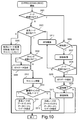
- FIG. 10 shows a flowchart of read processing of the distributed storage system.
- the processor 119 determines whether or not the computer node 101 has not been assigned to an access destination virtual page (hereinafter also simply referred to as a virtual page) with respect to the specified address (also referred to as the specified address) of the received read instruction. It judges with reference to 215 (S501).
- the designated address is designated by, for example, a virtual volume number and LBA.
- LBA is represented by the start LBA and the block length.
- the processor 119 determines whether exclusion is necessary (S506).
- the processor 119 refers to the virtual volume management table 218, determines that exclusion is not necessary when the owner node of the virtual volume is only the own node, and otherwise determines that exclusion is necessary.
- the processor 119 obtains exclusion (S507), and then determines again whether the computer node 101 is unallocated to a virtual page (S508). This is because a node may be assigned to the virtual page between S501 and S508 (that is, during the processing of S506 or S507).
- the processor 119 specifies a representative node uniquely determined from the read address using a hash function, requests arbitration from the representative node, and the representative node performs arbitration.
- the processor 119 releases the exclusion (S512), and proceeds to step S502.
- the processor 119 returns zero data (S509), and determines whether exclusion is necessary as in the determination in step S506 (S510). If exclusion is necessary (S510: Y), since the exclusion has already been acquired in S507, the processor 119 releases the exclusion (S511).
- the processor 119 determines whether the own node is assigned to the virtual page or whether another node is assigned to the virtual page. Specifically, the processor 119 refers to the page mapping table 215, identifies the node assigned to the virtual page, and determines whether the identified node is a local node or another node.
- step S501 When the computer node 101 has been assigned to the virtual page in step S501 (S501: N) and the own node has been assigned to the virtual page (S502: Y), the processor 119 refers to the deduplication mapping table 234. Then, it is determined whether a logical chunk has not been assigned to the virtual chunk (referred to as the virtual chunk) corresponding to the designated address (S503). In step S503, when the logical chunk is not allocated (S503: Y), the processor 119 returns zero data (S504). In step S503, when the logical chunk has been allocated (S503: N), the processor 119 secures its own cache area (S512).
- the cache data management information includes a dirty queue, a clean queue, and a free queue.
- the dirty queue is a list for managing dirty data in the memory.
- the dirty data is either user data for which redundant data has not been generated, user data for which redundant data has been generated but not reflected on the drive 113, or redundant data not yet reflected on the drive.
- the clean queue is a list for managing clean data in the memory.
- the clean data is either user data already reflected in the drive or redundant data already reflected in the drive.
- the free queue is a list for managing free areas on the memory.
- the free area is an unused cache area.
- the processor 119 In securing the cache area, the processor 119 refers to the cache information 204 and identifies the cache area associated with the target logical address. If there is no corresponding cache area, the processor 119 secures a new area from the free queue. When the free queue is empty, the processor 119 secures a new area from the clean queue. When the clean queue is empty, the processor 119 destages the area in the dirty queue and changes it to a free area.
- the processor 119 refers to the deduplication mapping table 234 and the pool volume management table 219 to determine whether a logical chunk corresponding to the virtual chunk (the logical chunk) exists in the pool volume of the own node. (S513). Specifically, the processor 119 first identifies the pool volume in which the logical chunk corresponding to the virtual chunk is stored with reference to the deduplication mapping table 234, and then identified with reference to the pool volume management table 219. The node to which the pool volume is provided is identified, and if the identified node is the own node, it is determined that the determination result in S513 is positive, otherwise the determination result in S513 is negative. judge.
- the processor 119 reads the data of the logical chunk from the pool volume of the local node, and the read data is a cache area secured in S512. And the data stored in the cache area is returned to the host (S514).
- the data of the logical chunk is in the pool volume of the other system node, so read data is transmitted and received between the own system node and the other system node. After that, the data of the logical chunk is returned to the host (S515). Specifically, the following processing is performed. That is, (1) the processor 119 of the own system node transmits a read request for data of the logical chunk to the other system node, and (2) the processor 119 of the other system node that has received the read request receives the pool volume of the other system node. The data of the logical chunk is read from the node, and the read data is transmitted to the own node.
- the processor 119 of the own node receives the transmitted data and stores it in the cache area secured in S512. Store and return the data stored in the cache area to the host.
- the history information is updated accordingly. Specifically, the “frequency of reading across duplicate data nodes” in the page load frequency table 216 and the “frequency of reading across duplicate data nodes” in the virtual chunk load frequency table 225 are updated.
- the processor 119 transfers a read command to the other system node (S505).
- the processor 119 does not cache read data in its own system. That is, if the virtual page allocation destination is another node, the processor 119 does not cache the read data in the local memory 118 (read-through), and the other node 101 caches the read data.
- the other node executes the process of FIG. 10 and returns data to the host via the own node.
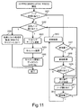
- FIG. 11 shows a flowchart of the synchronous write process. This process is executed when a write command is issued from a host (for example, an application program). This process stores the write data in the own pool volume.
- a host for example, an application program
- the processor 119 of the node 101 that has received the write command determines whether or not the computer node 101 is not assigned to an access destination virtual page (hereinafter simply referred to as a virtual page) (S601). Specifically, the processor 119 refers to the page mapping table 215 and searches for the node number of the corresponding computer node 101 from the designated address (virtual volume number and LBA) of the write instruction. The processor 119 determines whether the virtual page is unallocated to the computer node 101 by determining whether the corresponding node number is an invalid value.
- a plurality of applications are activated, and at least one node in the system operates each application.
- a data read request is often issued to a node that has received a data write command. Therefore, in this application, when a node receives a write request, the node preferentially stores the write request data in the storage area of the node. As a result, the probability of being able to read from the node in response to a read request increases, and it becomes possible to respond to the read request at high speed.
- the system throughput may be improved by distributing the data to a large number of nodes.
- the allocation destination storage area may be changed using a technique such as round robin according to the performance of the network 103 or the performance of the drive 113 connected to the node 101.
- the above allocation policy is not only based on an index of performance, but when a flash is used as the drive 113, an index such as a lifetime may be used to improve cost effectiveness.
- the processor 119 executes processing for assigning the computer node 101 to a virtual page.
- the processor 119 first determines whether or not it is necessary to exclusively update the page mapping table 215 (S607).
- the reason for acquiring the exclusion is to prevent a plurality of different computer nodes 101 from being assigned to the virtual page when the other node 101 assigns the computer node 101 to the virtual page at the same time.
- the processor 119 refers to the virtual volume management table 218 and determines that exclusion is necessary when the owner node includes a node other than the own node. When the owner node is only the own node, exclusion is not necessary. judge. When it is determined that exclusion is necessary (S607: Y), the processor 119 acquires exclusion (S608).
- the method for acquiring exclusion is the same as the method shown in the read processing described with reference to FIG.
- the processor 119 determines again whether or not the computer node 101 is not assigned to a virtual page (S609). This is because, after determining whether or not the computer node 101 has been assigned to the virtual page in step S601, it is possible that the exclusion has been acquired by another node before the exclusion is acquired in step S608.
- the processor 119 determines the computer node 101 to which a virtual page is assigned (S610). The processor 119 first checks whether there is a free area in its own pool volume.
- the target usage amount and the actual usage amount in the pool volume area control table 236 are referred to and it is determined whether the actual usage amount is smaller than the target usage amount.
- the processor 119 allocates the virtual page to the own node.
- the processor 119 locally mounts the pool volume of another system (another node) and allocates a page to the area.
- the processor 119 allocates the node to the virtual page (S611). Specifically, the processor 119 updates the correspondence relationship in the page mapping table 215.
- the processor 119 determines whether or not exclusion is necessary (S612). This determination is the same as in step S607. When exclusion is necessary (S612: Y), the processor 119 releases the acquired exclusion (S617). If exclusion is not necessary (S612: N), the processor 119 proceeds to step S602.
- the processor 119 determines whether or not the own node is allocated to the virtual page corresponding to the write instruction with reference to the page mapping table 215 (step 602).
- the processor 119 transfers the write command to the other node 101 (S606).
- the other node 101 executes the write process according to this flowchart.
- the processor 119 does not cache write data in its own system.
- the processor 119 updates the deduplication log structured mapping table 233 (S603).
- the write data is stored in a log structured format in the pool volume (the corresponding cache area).
- the processor 119 acquires the first unused logical chunk from the unused list 237C, and stores the acquired logical chunk in the valid list 237A. Then, the allocation destination of the access destination virtual chunk in the deduplication mapping table 234 is changed to the acquired unused logical chunk.
- the deduplication reverse mapping table 235 stores the association between the access destination virtual chunk and the acquired unused logical chunk, and deletes the association between the access destination virtual chunk and the allocation destination logical chunk. Further, the processor 119 refers to the de-duplication reverse mapping table 235, and when the logical chunk associated with the access destination virtual page is allocated to another virtual page, the processor 119 continues to the valid list 237A. Store. If the logical chunk associated with the access destination virtual page is not assigned to another virtual page, the logical chunk is moved from the valid list 237A to the invalid list 237B.
- the processor 119 determines the address (LBA etc.) in the virtual volume and the logical address in the pool volume.
- the correspondence relationship is recorded in the deduplication mapping table 234.
- the computer node 101 updates the virtual chunk data with new data
- the computer node 101 does not overwrite the corresponding logical chunk data with the new data, and overwrites the new data.
- the processor 119 records the correspondence relationship between the logical address in the pool volume and the address (LBA or the like) in the virtual volume in the deduplication reverse mapping table 235. Further, the processor 119 appropriately updates the pool volume area control table 236 in response to the update of the deduplication log structured mapping table 233.
- the processor 119 secures a cache in its own cache area 181 (S604).
- the method is the same as the method described with reference to FIG.
- the processor 119 writes the write data to the cache area secured in S604 (S605).
- the distributed storage system generates a redundant code between a plurality of computer nodes 101 using a known technique such as Erasure Coding and stores the generated redundant code in the computer node 101. It can also be configured as follows. In this case, in the synchronous write process, it is necessary to transmit one or both of (1) a part or all of the write data and (2) a redundant code generated from the write data to the other system node. Thereby, even if a failure occurs in the computer node 101, the user data can be recovered.
- FIG. 12 shows a flowchart of the back-end write process. This process is executed asynchronously with the host I / O when there is host dirty data on the cache 181, that is, write data for which no redundant code has been generated. In this process, a redundant code corresponding to the write data is generated, and then the write data and the generated redundant code are written to the drive (113).
- the size of the write data is equal to the size of the stripe.
- the host dirty data is managed in a dirty queue.
- the processor 119 selects write data for which no redundant code has been generated (S801). The selected write data is called the write data. Next, the processor 119 generates a redundant code corresponding to the write data (S802). Next, the processor 119 writes the write data and the generated redundant code to the drive (113) (S803). Next, the processor 119 determines whether there is write data for which no redundant code has been generated (S804). If the determination result is affirmative (S804: Y), the processor 119 proceeds to S801, and if the determination result is negative (S804: N), the process ends.
- FIG. 13A shows a flowchart of deduplication processing.
- target data for deduplication such as node deduplication, site deduplication, and geo deduplication is determined, and each deduplication is performed on the target data.
- target data for deduplication cancellation such as node deduplication cancellation, site deduplication cancellation, and geo deduplication cancellation is determined, and each deduplication cancellation is performed on the target data.
- This process is started asynchronously with the host I / O. For example, it may be activated at a timing designated by the user, or may be activated at a predetermined timing. As the timing, a timing at which the user gives an instruction to start processing, a timing for every fixed period, a timing at which the amount of new write data exceeds a predetermined amount, or the like can be used. This process is also executed by cooperation of a plurality of computer nodes 101.
- the processor 119 of the computer node 101 having a predetermined node number determines a master node (S9001).
- the master node is a computer node 101 that controls processing in the deduplication processing of FIG. 13A in which a plurality of computer nodes 101 cooperate.
- the master node is any one of the computer nodes 101 in the distributed storage system.
- the computer nodes 101 other than the master node in the distributed storage system are slave nodes.
- the slave node operates in response to an instruction from the master node.
- the master node also has a role as a slave node.
- the FPT 231 is updated. Specifically, the entry (row) corresponding to the updated area of the virtual volume is registered in the FPT 231 and the entry (row) corresponding to the old FP is deleted from the FPT 231.
- the master node processor 119 instructs one of the slave nodes to create the FPT update log 239 (S9002).
- the processor 119 (referred to as the processor) of the slave node (referred to as the relevant node) that has received the instruction specifies the update area of the virtual volume (S9003). Specifically, the following processes (1) and (2) are performed. (1) The processor refers to the page mapping table 215 and identifies an entry whose node number column in the page mapping table 215 is the node. It indicates that the data of the virtual volume area corresponding to the entry is allocated to the node. (2) The processor performs the following processes (2-1) to (2-2) for each identified entry.
- the processor refers to the “status” of the virtual chunk in the deduplication mapping table 234 corresponding to the entry, and has the virtual chunk been updated since the previous execution of the deduplication process in FIG. 13A? (Referred to as determination A). (2-2) If the determination result of determination A is affirmative (YES), the virtual volume area corresponding to the entry is specified as an update area. Through the processes of (2-1) and (2-2), the processor identifies update areas (updated virtual chunks) of one or more virtual volumes.
- the processor creates the FPT update log 239 based on the information on the specified update area of the virtual volume (S9004). Specifically, the following processes (1) and (2) are performed for each of the update areas of the virtual volume identified in S9003. One of the update areas to be processed is called the virtual chunk.
- the processor reads the data of the virtual chunk, calculates the FP of the read data, and calculates the calculated FP together with the address (virtual volume number, LBA, address range) of the virtual chunk and the “operation”. Stored in the FPT update log 239 in the node.
- the value of “operation” is “registration”.
- the address is “information for identifying a virtual chunk”.
- the processor reads the value of “FP” in the deduplication mapping table 234 corresponding to the virtual chunk, and uses the read FP as the address of the virtual chunk (virtual volume number, LBA, address range) and “ Stored in the FPT update log 239 in the node together with “operation”
- the value of “operation” is “delete”.
- the address is “information for identifying a virtual chunk”.
- the combination of “FP” and “information for identifying virtual chunk” stored in the FPT update log 239 of the node in (1) above is an entry to be registered in the FPT 231 of the distributed storage system.
- the pair of “FP” and “information for identifying virtual chunk” stored in the FPT update log 239 of the node in (2) is an entry to be deleted from the FPT 231 of the distributed storage system.
- the processor 119 of the master node determines whether an instruction to create the FPT update log 239 has been executed for all slave nodes (S9005). If the determination result is affirmative (S9005: Y), the process proceeds to S9006. If the determination result is negative (S9005: N), the process proceeds to S9002, and an instruction to the next slave node is executed.
- processing of S9003 to S9004 is executed by a plurality of different computer nodes 101, and may be executed in parallel. In that case, the master node needs to wait until the processing of S9003 to S9004 is completed in all the slave nodes.
- the master node processor 119 instructs one of the slave nodes (the slave node) to transmit the FPT update log (S9006).
- the computer node 101 transmits / receives the FPT update log (S9007). Specifically, the following processes (1) to (3) are performed.
- the slave node receiving the instruction from the master node divides the FPT update log 239 stored in the slave node.
- a specific method is the same as the “method of dividing FPT 231 into a plurality of partial tables” in the description of the configuration example of FPT 231 in FIG.
- a storage destination node of the divided FPT update log (referred to as a partial FPT update log) (corresponding to the arrangement node of the divided FPT 231 in the description of FIG. 7A) is called a responsible node.
- FP value% N in the description of FIG.
- the partial FPT update log may be referred to as a partial FPT update log 239.
- the slave node transmits each partial FPT update log 239 created in (1) to the corresponding responsible node.
- Each responsible node receives the partial FPT update log 239 transmitted in (2).
- the processes (2) and (3) are executed by the processor 119 of each computer node 101 in accordance with instructions from the master node.
- the responsible node that has received the partial FPT update log 239 updates the FPT 231 based on the received partial FPT update log 239 (referred to as the partial FPT update log 239) (S9008). Specifically, the following processes (1) to (3) are performed.
- the responsible node corresponds to each row in which the value of “operation” (“operation” in FIG. 7B) is “deleted” among the entries included in the partial FPT update log 239 (referred to as the FPT update log entry).
- the following processing is executed. That is, from the row of the FPT 231 in the node in charge, the row where the FP value of the FPT 231 is equal to the FP value of the FPT update log entry is deleted.
- the responsible node has, in the entries included in the partial FPT update log 239, each row whose value of “operation” (“operation” in FIG. 7B) is “registered” (referred to as the relevant FPT update log entry).
- operation in FIG. 7B
- the relevant FPT update log entry a new line created based on the contents of the FPT update log entry is added to the FPT 231 in the node in charge.
- FP virtual volume number
- LBA virtual volume number
- address range in the new row are respectively equal to “FP”, “virtual volume number”, “LBA”, and “address range” in the FPT update log entry.
- the master node determines whether an instruction to send the FPT update log 239 has been executed for all slave nodes (S9009). If the determination result is affirmative (S9009: Y), the process proceeds to S9010. If the determination result is negative (S9009: N), the process proceeds to S9006, and an instruction to the next slave node is executed.
- processing of S9007 to S9008 is executed by a plurality of different computer nodes 101, and may be executed in parallel. In that case, the master node needs to wait until the processing of S9007 to S9008 is completed in all the slave nodes.
- the master node executes node deduplication processing of FIG. 13B described later on each computer node 101 (S9010).
- the master node executes a node crossing deduplication process of FIG. 13C described later (S9011).
- the master node executes a node crossing deduplication cancellation process of FIG. 13E described later (S9012).
- the performance degradation due to deduplication can be suppressed by first executing node deduplication without increasing communication between computer nodes 101 at the time of IO processing due to execution of deduplication, and then executing deduplication across nodes.
- FIG. 13B shows a flowchart of node deduplication processing. This process is started by the master node. In this process, node deduplication is performed on duplicate data in each computer node 101.
- the processor 119 of the master node selects one of the slave nodes (S9101).
- the processor 119 of the master node instructs the slave node selected in the previous step to execute node deduplication (S9102).
- the processor 119 (referred to as the processor) of the slave node (the slave node) that has received an instruction to execute node deduplication from the master node, performs node duplication (not shown) based on the information of the FPT 231 in each computer node 101.
- the exclusion candidate list 240 is created (S9103). Specifically, the following processes (1) to (5) are executed.
- the processor Since the FPT 231 is distributed and held in a plurality of computer nodes 101, the processor stores the node deduplication candidate list related to the slave node in each other computer node 101 (referred to as the node). A part of 240 is instructed.
- the processor 119 of the node creates a node deduplication list related to the slave node. Specifically, the processor 119 of the node has the node number of the page mapping table 215 corresponding to the address (virtual volume number, LBA, address range) of the row of the FPT 231 in the node. Extract the line that matches the node number of the slave node. A table composed of the extracted rows is a part of the node deduplication candidate list 240 related to the slave node.
- the processor 119 of the node transmits a part of the node deduplication candidate list 240 created in (2) to the slave node.
- the processor creates a part of the node deduplication candidate list 240 related to the slave node by the same processing as in (2) above.
- the processor creates a node deduplication candidate list 240 by concatenating a part of the node deduplication candidate list 240 created in steps (1) to (4) above. Note that the data structures of the FPT 231 and the node deduplication candidate list 240 are the same.
- the processor selects one pair of node deduplication candidates (S9104). Specifically, one pair of rows having the same “FP” value is selected from the rows of the node deduplication candidate list 240.
- the processor prepares duplication candidate data (S9105). Specifically, for each row included in the pair selected in S9104, the processor reads the duplicate candidate data pair from the virtual volume area corresponding to each row to the cache 181.
- the processor executes binary comparison of the duplication candidate data, and determines whether the contents of the duplication candidate data pair completely match (S9106). Specifically, the pair of duplication candidate data read to the cache 181 in S9105 is compared with Byte-by-Byte to determine whether the contents of the duplication candidate data pair completely match.
- the processor selects any one of duplicate data (corresponding to two rows in the node deduplication candidate list 240) corresponding to the pair selected in S9104 as deletion target data (S9108).
- the processor updates the address mapping corresponding to the data selected as the data to be deleted in the previous step (S9109). Specifically, the following processes (1) to (4) are executed.
- mapping specified in (1) above is updated so that the mapping destination is the address of the pool volume specified in (2) above.
- deduplication reverse mapping table 235 is updated in order to add reverse mapping that maps from the pool volume address specified in (2) to the virtual volume address in (1).
- the processor determines whether or not the processing for all pairs of node deduplication candidates has been completed, and if the determination result is affirmative (S9110: Y), the process proceeds to S9111, otherwise (S9110: N), the process proceeds to S9104, and the process for the next pair of node deduplication candidates is executed.
- the master node determines whether or not the processing related to all the slave nodes has been completed. If the determination result is affirmative (S9111: Y), the node deduplication processing ends, and if not (S9111: N), the process proceeds to S9101, and the next slave node is selected.
- FIG. 13C and FIG. 13D are flowcharts of the cross-node deduplication processing. This process is executed by the master node and the slave node. In this processing, node-to-node deduplication (site deduplication, geo deduplication) is executed on duplicate data stored in different computer nodes 101 in the distributed storage system.
- the information used for determining whether or not to perform deduplication across nodes includes at least one of variables Y1, Y2, and Y3.
- the variables Y1, Y2, and Y3 are respectively “predicted value of network load due to duplicate data node crossing read caused by cross node deduplication”, “predicted value of average response time of distributed storage system”, and “distributed type”. The predicted value of the average throughput of the storage system.
- the master node may refer to various tables stored in the master node and may refer to or update various tables stored in other than the master node.
- the master node does not need to communicate with the other computer node 101, but in the latter case, the master node needs to request the other computer node 101 to refer to or update the table.
- the processor 119 of the master node refers to (or updates) the XX table”.
- the processor 119 of the master node sets the value of the variable Y1 to 0 (S9201).
- the processor 119 of the master node sorts the data units in ascending order based on the IO frequency (S9202). Specifically, a copy of the virtual chunk load frequency table 225 is created, and the copied table is sorted in ascending order based on the IO frequency.
- the processor 119 of the master node selects one data unit in ascending order regarding the IO frequency (S9203). Specifically, one row is selected in ascending order regarding the IO frequency from the table sorted in S9202. The selected data unit is called the data unit.
- the processor 119 of the master node selects one virtual chunk included in the data unit (S9204). Since the “data unit” is now “virtual chunk”, the virtual chunk to be selected is the virtual chunk itself corresponding to the row selected in S9203. The virtual chunk selected in S9204 is referred to as the first virtual chunk.
- the processor 119 of the master node determines whether there is a virtual chunk having the same FP value as the FP value of the first virtual chunk (S9205). Specifically, the following processes (1) to (3) are executed.
- the processor 119 of the master node specifies the FP value of the data of the first virtual chunk by referring to the FP of the deduplication mapping table 234 corresponding to the first virtual chunk.
- the identified FP value is referred to as the FP value.
- the master node processor 119 refers to the FPT 231 in the node in charge of the FP value (referred to as the node in charge), and has an entry having the FP value (however, an entry corresponding to the first virtual chunk) Are different entries).
- the node number corresponding to the node in charge uses the same method as that used in the description of FIG. 7A, such as a method of determining based on a calculation formula such as “FP value% N”.
- the processor 119 of the master node selects one virtual chunk (referred to as the second virtual chunk) in which data having the same FP value as that of the first virtual chunk data is stored (S9206). Specifically, the following processes (1) to (2) are executed.
- the master node processor 119 refers to the FPT 231 in the node in charge of the FP value (referred to as the node in charge), and has an entry having the FP value (however, an entry corresponding to the first virtual chunk) Identify different entries). (2) Select one entry from the specified entries. The virtual chunk corresponding to the selected entry is the second virtual chunk.
- the processor 119 of the master node determines whether or not deduplication across nodes can be performed between the first virtual chunk and the second virtual chunk (S9207). Specifically, the following processes (1) to (3) are executed.
- the master node processor 119 identifies the pool volume corresponding to the first virtual chunk with reference to the deduplication mapping table 234, and then identified with reference to the pool volume management table 219.
- the computer node 101 corresponding to the pool volume is specified.
- the processor 119 of the master node performs the same processing as (1) above on the second virtual chunk, and specifies the computer node 101 corresponding to the pool volume corresponding to the second virtual chunk. .
- the deduplication effect management table 232 is a table for managing how many logical chunks having a certain FP are deduplicated by node deduplication, site deduplication, and geo deduplication in the distributed storage system. .
- the information of reverse mapping in the deduplication reverse mapping table 235 is used.
- the reverse mapping of the deduplication reverse mapping table 235 one or more virtual chunks are associated with one logical chunk (corresponding to the data 250 in FIG. 8) (provided that the logical chunk is a valid logical chunk). .
- reverse mapping related to valid logical chunks is classified into one of the following two types. That is, there are two types: (1) main reverse mapping and (2) sub reverse mapping.
- the main reverse mapping in (1) is a reverse mapping that is always associated with a valid logical chunk, and is a reverse mapping that does not contribute to data reduction by deduplication (node deduplication, site deduplication, geo deduplication). is there.
- the sub-inverse mapping (2) is an inverse mapping that is associated with zero or more valid logical chunks, and is an inverse mapping that contributes to reducing the amount of data by deduplication (same as above).
- the main reverse mapping is a reverse mapping created when a logical chunk is allocated to a virtual chunk by writing data, and the sub reverse mapping is created when a plurality of virtual chunks are associated with one logical chunk by deduplication. Inverse mapping. However, it is not always necessary to select the reverse mapping created at the writing opportunity as the main reverse mapping. If multiple reverse mappings are associated with a valid logical chunk, any one reverse mapping of the multiple reverse mappings can be selected as the main reverse mapping.
- the sub-inverse mapping in (2) above is further reclassified into one of three types. That is, there are three types: (2-1) node sub reverse mapping, (2-2) site sub reverse mapping, and (2-3) geo sub reverse mapping. (2-1), (2-2), and (2-3) are sub-inverse mappings related to node deduplication, site deduplication, and geo deduplication, respectively.
- a computer node 101 corresponding to a certain logical chunk (referred to as the logical chunk) (a computer corresponding to the logical chunk by referring to the pool volume management table 219 based on the pool volume number corresponding to the logical chunk)
- the node 101 can be specified) is called a first node, and the page mapping table 215 is set based on a computer node 101 (a virtual volume number corresponding to the virtual chunk) corresponding to a certain virtual chunk (called the virtual chunk).
- the computer node 101 corresponding to the virtual chunk can be identified by referring to the second node). It is assumed that a certain sub-inverse mapping (referred to as the sub-inverse mapping) associates the logical chunk with the virtual chunk.
- the sub reverse mapping is a node sub reverse mapping.
- the sub-inverse mapping is site sub-inverse mapping.
- the sub-inverse mapping is a geo-sub-inverse mapping.
- the row (referred to as the row) of the deduplication effect management table 232 can be set by the following method. That is, when the computer node 101 related to the row is called the node and the FP related to the row is called the row FP, the “node deduplication reduction number” and “site deduplication reduction” in the deduplication effect management table 232 "Number” and “geo deduplication reduction number” are the total number of node sub reverse mappings and total number of site sub reverse mappings associated with logical chunks having the same value FP as the row FP in the node, respectively. , Equal to the total number of geosub-inverse mappings.
- step S9208 the processor 119 of the master node determines a node crossing deduplication execution determination formula. This step corresponds to the determination method described in the “determination method (2) for execution of deduplication across nodes” in FIG. Specifically, the following processes (1) to (2) are executed.
- the processor 119 of the master node updates the row (the row) of the deduplication effect management table 232 corresponding to the FP value. Specifically, the master node processor 119 determines the total number of node sub reverse mappings, the total number of site sub reverse mappings, and the total number of geo sub reverse mappings associated with the logical chunk corresponding to the FP in the distributed storage system, respectively. Set to “node deduplication reduction number”, “site deduplication reduction number”, and “geo deduplication reduction number” in the row. The processor 119 of the master node needs to request other computer nodes 101 to refer to and update the table as appropriate.
- Cross-node deduplication execution determination formula r ⁇ “threshold for cross-node deduplication execution determination formula”
- the “threshold for the node crossing deduplication execution determination formula” is a predetermined value, and the information is stored in the memory 118 (not shown).
- step S9209 if the determination result in S9208 is positive, the processor 119 of the master node proceeds to S9210, and if the determination result in S9208 is negative, the process proceeds to S9216.
- steps S9210 to S9215 node crossing deduplication (site deduplication or geo deduplication) may be executed.
- the processor 119 of the master node selects one computer node 101 as a slave node (S9210).
- the selected computer node 101 is called the slave node. If the slave node is a computer node 101 in which a logical chunk corresponding to the first virtual chunk or the second virtual chunk is stored, the data transfer amount in S9211 can be reduced.
- the processor 119 of the master node transfers the data in the first logical chunk to the slave node in the computer node 101 in which the logical chunk corresponding to the first virtual chunk (referred to as the first logical chunk) is stored. Instructs to transmit, and transmits the data in the second logical chunk to the slave node to the computer node 101 in which the logical chunk corresponding to the second virtual chunk (referred to as the second logical chunk) is stored.
- the computer node 101 receiving the instruction transmits data according to the instruction (S9211).
- the slave node executes binary compare and transmits the result to the master node (S9212). Specifically, the slave node compares the data in the first logical chunk with the data in the second logical chunk by byte-by-byte, and determines whether the contents of the data completely match. . The slave node transmits the determination result (“match” or “mismatch”) to the master node.
- the processor 119 of the master node determines data related to a data unit with a lower IO frequency as data to be deleted (S9214). Specifically, the processor of the master node specifies the IO frequency of the first virtual chunk and the second virtual chunk based on the virtual chunk load frequency table 225, and selects a logical chunk corresponding to a virtual chunk with a lower IO frequency. Determine the data to be deleted.
- the IO frequency of the virtual page corresponding to the first virtual chunk and the virtual page corresponding to the second virtual chunk is specified based on the page load frequency table 216, and the virtual page corresponding to the smaller IO frequency is supported.
- a logical chunk may be determined as data to be deleted.
- the processor 119 of the master node updates the address mapping corresponding to the data determined as the deletion target data in S9214 (S9215).
- a specific method is the same as that of S9109.
- the processor 119 of the master node sets an invalid value in the “frequency of reading across duplicate data nodes” in the virtual chunk load frequency table 225 regarding the virtual chunk corresponding to the data to be deleted.
- the processor 119 of the master node determines whether there is an unprocessed second virtual chunk (S9216). If the determination result is affirmative (S9216: Y), the process proceeds to S9217, and the determination result is negative. If so (S9216: N), the process proceeds to S9206.
- the processor 119 of the master node determines whether there is an unprocessed first virtual chunk (S9217). If the determination result is affirmative (S9217: Y), the process proceeds to S9218, and the determination result is negative. If so (S9217: N), the process proceeds to S9204.
- the processor 119 of the master node updates the values of Y1, Y2, and Y3 (S9218). Specifically, the following processes (1) to (3) are executed.
- “ ⁇ ” is “predicted value of IO frequency of read across redundant data nodes related to the data unit selected in S9203”.
- the “frequency of reading across duplicate data nodes” in the virtual chunk load frequency table 225 for the data unit selected in S9203 can be used.
- the value of “ ⁇ ” is the I / O related to the read managed by the virtual chunk load frequency table 225.
- a frequency (access frequency) value can be used.
- the I / O frequency is the I / O frequency related to the data unit selected in S9203.
- the value of “ ⁇ ” is an approximate value of the frequency of reads across overlapping data nodes.
- the master node processor 119 calculates Y2 by the following calculation formula and sets the calculated value to Y2.
- “I” indicates the row number of the table (called the table) sorted in S9202.
- “N” is a number indicating which row in the table the data unit corresponds to.
- “M” is a number indicating the total number of rows in the table.
- R i is the response time (average response time) of the data unit.
- W i is a weight for the response time of the data unit (note that if the denominator of the W i calculation formula is 0, the value of W i is 0).
- L i is the IO frequency of the data unit. The value of R i and L i is specified by the virtual chunk load frequency table 225.
- Cases (a) to (c) will be described.
- the computer node 101 (computer node 101 specified by the page mapping table 215) corresponding to the data unit (here, virtual chunk) is called the first node, and corresponds to the row number “i” of the table.
- a computer node 101 (computer node 101 specified by the pool volume management table 219) corresponding to a logical chunk corresponding to a data unit (here, a virtual chunk) is referred to as a second node.
- Case (a) is a case where the first node and the second node are the same.
- Case (b) is a case where the first node and the second node are different, but the second node and the second node are in the same site.
- Case (c) is a case where the first node and the second node are in different sites.
- Ra may be a preset value, or an average value of response times in each IO process (IO process for accessing data in the computer node 101) may be used.
- R b may be a preset value, or may use an average value of response times in each IO process (an IO process that accesses data across different computer nodes 101 in the site).
- R c may be a preset value, or may use an average value of response times in each IO process (an IO process that accesses data across computer nodes 101 in different sites).
- the master node processor 119 calculates Y3 according to the following calculation formula, and sets the calculated value to Y3.
- the symbols in the following calculation formula are the same as those in the calculation formula (2).
- the value of Y3 may be different from the actual “average throughput of the distributed storage system”.
- the value of Y3 may be calculated based on a calculation formula other than the following calculation formula. For the calculation of Y3, the IO load value of each virtual chunk, the following S value, the above Ri value, the above Ra value, the above R b value, the above R c value, Any or a combination may be used.
- the processor 119 of the master node may determine any one or a combination of the two inequalities “Y1> T1”, “Y2> T2”, and “Y3 ⁇ T3” (“unprocessed” It is necessary to determine whether or not there is no data unit.)
- the load on the IO load (network load due to duplication of data nodes across reads", “average response time”, or “average throughput”) It is possible to suppress the influence within a certain range.
- the master node processor 119 stores the data unit last selected in S9203 as a data unit threshold (corresponding to P in FIG. 1).
- FIG. 13E shows a flowchart of the cross-node deduplication cancellation process. This process cancels the deduplication across nodes for virtual chunks that are determined not to be deduplicated across nodes.
- the processor 119 of the master node selects one data unit after the data unit threshold in ascending order. Specifically, the processor 119 of the master node selects one row after the row corresponding to the data unit threshold stored in S9220 in ascending order with respect to the IO frequency among the rows of the table sorted in S9202. The selected data unit is called the data unit.
- the processor 119 of the master node selects one virtual chunk included in the data unit. Since the “data unit” is now “virtual chunk”, the virtual chunk to be selected is the virtual chunk itself corresponding to the row selected in S9301. The virtual chunk selected in S9302 is referred to as the third virtual chunk.
- the processor 119 of the master node determines whether the third virtual chunk has been de-duplicated across nodes.
- the processor 119 of the master node assigns the computer node 101 corresponding to the third virtual chunk (the computer node 101 corresponding to the third virtual chunk specified by the page mapping table 215) to the node A. As specified.
- the processor 119 of the master node identifies the computer node 101 storing the logical chunk (referred to as the logical chunk) corresponding to the virtual chunk as the node B. Specifically, the processor 119 of the master node first identifies the pool volume corresponding to the virtual chunk using the deduplication mapping table 234, and then corresponds to the pool volume identified using the pool volume management table 219.
- the computer node 101 is specified, and the specified computer node 101 is specified as a node B.
- the processor 119 of the master node is a computer node 101 in which the node A and the node B are different, and the number of deduplication inverse mappings associated with the logical chunk is 2 or more (corresponding to the logical chunk) Whether or not the number of indexes in the de-duplication reverse mapping table 235 is 2 or more). If the determination result is affirmative (S9303: Y), the process proceeds to S9304. If not (S9303: N), the process proceeds to S9304.
- the master node processor 119 reads the data of the third virtual chunk.
- the master node processor 119 writes the data read in S9304 to the third virtual chunk.
- the specific processing of writing is the same as the processing of FIG.
- step S9304 and step S9305 node-overlap deduplication for the third virtual chunk is released.
- the steps of S9304 and S9305 may be executed in the computer node 101 (computer node 101 specified by the page mapping table 215) corresponding to the third virtual chunk instead of the master node.
- the processor 119 of the master node determines whether there is an unprocessed third virtual chunk. If there is no unprocessed third virtual chunk (S9306: Y), the process proceeds to S9307; otherwise (S9306: N), the process proceeds to S9302.
- the master node processor 119 determines whether there is an unprocessed data unit. If there is no unprocessed data unit (S9307: Y), the cross-node deduplication cancellation process is terminated, and if not (S9307: N), the process proceeds to S9301.
- cross-node deduplication elimination By cross-node deduplication elimination, cross-node deduplication cancellation can be applied to a data unit with a high IO load. Thereby, IO performance of a data unit with high IO frequency can be improved.
- FIGS. 13A to 13E virtual pages are used as data units instead of virtual chunks.
- the page load frequency table 216 is used in place of the virtual chunk load frequency table 225 in S9202 of FIG. 13C. While performing deduplication in units of virtual chunks, managing the load frequency in units of virtual pages larger in size than the virtual chunks eliminates the need for management information in units of virtual chunks such as the virtual chunk load frequency table 225. Information can be reduced.
- the value of “ ⁇ ” used to update “Y1” in S9218 is the “duplicate data node straddle read” in the page load frequency table 216 for the data unit selected in S9203.
- the frequency is used.
- the IO frequency (access frequency) related to reading in the page load frequency table 216 may be used as the value of “ ⁇ ”. Since the value of “ ⁇ ” in the present modified embodiment is an approximate value of the actual value of “ ⁇ ”, the value of Y1 calculated based on the value of “ ⁇ ” in the present modified embodiment is the actual Y1. It is an approximate value of.
- the advantages of using the page load frequency table 216 are as described above.
- the deduplication technology of the present disclosure makes it possible to execute deduplication across nodes while suppressing performance degradation, and can achieve both a high data amount reduction effect and high performance. In addition, it is possible to avoid the occurrence of a bottleneck due to the network. Specifically, by executing the cross-node deduplication processing after the node deduplication processing is executed, deduplication can be performed in the order of small influence on performance, and performance degradation due to deduplication processing can be reduced. By sorting the data units in order of IO frequency and performing deduplication across nodes so that the impact on performance falls within a predetermined range in ascending order, it is possible to cross the nodes preferentially for data units that have little impact on IO load.
- Deduplication is performed, so that both high data volume reduction and high performance can be achieved.
- the number of inverse mappings of the mapping destinations of the data units to be determined for the node-to-node deduplication is equal to or less than a predetermined threshold, a high data amount reduction effect and high performance can be achieved by executing the node-to-node deduplication.
- this invention is not limited to the above-mentioned Example, Various modifications are included.
- the above-described embodiments have been described in detail for easy understanding of the present invention, and are not necessarily limited to those having all the configurations described.
- a part of the configuration of one embodiment can be replaced with the configuration of another embodiment, and the configuration of another embodiment can be added to the configuration of one embodiment.
- each of the above-described configurations, functions, processing units, and the like may be realized by hardware by designing a part or all of them with, for example, an integrated circuit.
- Each of the above-described configurations, functions, and the like may be realized by software by interpreting and executing a program that realizes each function by the processor.
- Information such as programs, tables, and files for realizing each function can be stored in a recording device such as a memory, a hard disk, or an SSD, or a recording medium such as an IC card or an SD card.
- control lines and information lines indicate what is considered necessary for the explanation, and not all control lines and information lines on the product are necessarily shown. In practice, it may be considered that almost all the components are connected to each other.
Landscapes
- Engineering & Computer Science (AREA)
- Theoretical Computer Science (AREA)
- Physics & Mathematics (AREA)
- General Engineering & Computer Science (AREA)
- General Physics & Mathematics (AREA)
- Human Computer Interaction (AREA)
- Information Retrieval, Db Structures And Fs Structures Therefor (AREA)
Abstract
Dans un système de stockage réparti comprenant une pluralité de nœuds conformément à l'invention, un premier nœud de la pluralité de nœuds détermine si les premières données, qui sont écrites dans une première zone partielle virtuelle gérée par le premier nœud parmi une pluralité de zones partielles virtuelles, sont identiques à des données dans des zones partielles virtuelles gérées par d'autres nœuds de la pluralité de nœuds, et si une zone partielle virtuelle gérée par un quelconque autre nœud stocke des données écrites identiques aux premières données, le premier nœud procède à une déduplication inter-nœuds. Soit la première zone partielle virtuelle est réaffectée à la zone partielle logique à laquelle est actuellement affectée la zone partielle virtuelle qui stocke les données identiques, soit la zone partielle virtuelle qui stocke les données identiques est réaffectée à la zone partielle logique à laquelle est actuellement affectée la première zone partielle virtuelle. Si la charge E/S du premier nœud chute en dessous d'une première valeur seuil au terme de la déduplication inter-nœuds dans la première zone partielle virtuelle, le premier nœud procède à une déduplication inter-nœuds dans une seconde zone partielle virtuelle gérée par le premier nœud parmi la pluralité de zones partielles virtuelles qui sont obtenues en divisant une zone de stockage virtuelle.
Priority Applications (3)
| Application Number | Priority Date | Filing Date | Title |
|---|---|---|---|
| US15/553,174 US10346075B2 (en) | 2015-03-16 | 2015-03-16 | Distributed storage system and control method for distributed storage system |
| PCT/JP2015/057615 WO2016147281A1 (fr) | 2015-03-16 | 2015-03-16 | Système de stockage réparti et procédé de commande pour système de stockage réparti |
| CN201580074636.3A CN107209714B (zh) | 2015-03-16 | 2015-03-16 | 分布式存储系统及分布式存储系统的控制方法 |
Applications Claiming Priority (1)
| Application Number | Priority Date | Filing Date | Title |
|---|---|---|---|
| PCT/JP2015/057615 WO2016147281A1 (fr) | 2015-03-16 | 2015-03-16 | Système de stockage réparti et procédé de commande pour système de stockage réparti |
Publications (1)
| Publication Number | Publication Date |
|---|---|
| WO2016147281A1 true WO2016147281A1 (fr) | 2016-09-22 |
Family
ID=56918474
Family Applications (1)
| Application Number | Title | Priority Date | Filing Date |
|---|---|---|---|
| PCT/JP2015/057615 Ceased WO2016147281A1 (fr) | 2015-03-16 | 2015-03-16 | Système de stockage réparti et procédé de commande pour système de stockage réparti |
Country Status (3)
| Country | Link |
|---|---|
| US (1) | US10346075B2 (fr) |
| CN (1) | CN107209714B (fr) |
| WO (1) | WO2016147281A1 (fr) |
Cited By (3)
| Publication number | Priority date | Publication date | Assignee | Title |
|---|---|---|---|---|
| JP2020086477A (ja) * | 2018-11-15 | 2020-06-04 | 株式会社日立製作所 | 大規模ストレージシステム及び大規模ストレージシステムにおけるデータ配置方法 |
| CN111527476A (zh) * | 2017-12-21 | 2020-08-11 | 思科技术公司 | 针对数据密集型工作负载进行跨云资源放置的系统和方法 |
| US10884642B2 (en) | 2019-03-27 | 2021-01-05 | Silicon Motion, Inc. | Method and apparatus for performing data-accessing management in a storage server |
Families Citing this family (16)
| Publication number | Priority date | Publication date | Assignee | Title |
|---|---|---|---|---|
| CN107294799B (zh) * | 2016-03-31 | 2020-09-01 | 阿里巴巴集团控股有限公司 | 一种分布式系统中节点的处理方法和装置 |
| US10977215B2 (en) * | 2017-08-08 | 2021-04-13 | International Business Machines Corporation | System and method for storage optimization in a de-duplication system |
| CN108268219B (zh) * | 2018-02-01 | 2021-02-09 | 杭州宏杉科技股份有限公司 | 一种处理io请求的方法及装置 |
| US10642689B2 (en) * | 2018-07-09 | 2020-05-05 | Cisco Technology, Inc. | System and method for inline erasure coding for a distributed log structured storage system |
| CN109614403B (zh) * | 2018-10-24 | 2020-03-06 | 北京三快在线科技有限公司 | 集群服务节点的数据一致性校验方法及装置 |
| KR102737418B1 (ko) * | 2018-12-13 | 2024-12-04 | 에스케이하이닉스 주식회사 | 데이터 처리 시스템 및 그것의 동작방법 |
| TWI695322B (zh) * | 2019-01-18 | 2020-06-01 | 旺宏電子股份有限公司 | 記憶體及記憶體操作方法 |
| JP6857673B2 (ja) * | 2019-02-14 | 2021-04-14 | 株式会社日立製作所 | マルチストレージノードシステム、マルチストレージノードシステムの容量管理方法 |
| CN110414361A (zh) * | 2019-07-02 | 2019-11-05 | 青岛海洋科学与技术国家实验室发展中心 | 分布式机器视觉数据采集分析方法和系统 |
| CN110427347A (zh) * | 2019-07-08 | 2019-11-08 | 新华三技术有限公司成都分公司 | 重复数据删除的方法、装置、存储节点及存储介质 |
| CN114816251A (zh) | 2019-07-26 | 2022-07-29 | 华为技术有限公司 | 数据处理方法、装置及计算机存储可读存储介质 |
| CN110515916B (zh) * | 2019-07-26 | 2022-12-23 | 济南浪潮数据技术有限公司 | 一种主从分布式文件处理方法、主节点、从节点及系统 |
| CN110704232B (zh) * | 2019-10-10 | 2023-03-14 | 广东工业大学 | 一种分布式系统中失效节点的修复方法、装置和设备 |
| US11636041B2 (en) * | 2020-10-12 | 2023-04-25 | Seagate Technology Llc | Object storage data storage systems and methods |
| CN114265551B (zh) * | 2021-12-02 | 2023-10-20 | 阿里巴巴(中国)有限公司 | 存储集群中的数据处理方法、存储集群、存储节点及设备 |
| US20240256166A1 (en) * | 2023-01-26 | 2024-08-01 | Dell Products L.P. | Offloading data compression during restores to a data processing unit in a deduplication backup system |
Citations (3)
| Publication number | Priority date | Publication date | Assignee | Title |
|---|---|---|---|---|
| JP2010277289A (ja) * | 2009-05-28 | 2010-12-09 | Fujitsu Ltd | 管理プログラム、管理装置および管理方法 |
| WO2013038510A1 (fr) * | 2011-09-13 | 2013-03-21 | 株式会社日立製作所 | Système de gestion et procédé de gestion pour système de stockage qui effectue une commande sur la base de performances requises attribuées à des volumes virtuels |
| JP2015503174A (ja) * | 2012-12-12 | 2015-01-29 | 華為技術有限公司Huawei Technologies Co.,Ltd. | クラスタシステムデータ処理方法及び装置 |
Family Cites Families (9)
| Publication number | Priority date | Publication date | Assignee | Title |
|---|---|---|---|---|
| US8775373B1 (en) * | 2008-05-21 | 2014-07-08 | Translattice, Inc. | Deleting content in a distributed computing environment |
| US8572137B2 (en) | 2009-09-08 | 2013-10-29 | International Business Machines Corporation | Data de-duplication in a distributed network |
| US8898120B1 (en) * | 2011-10-09 | 2014-11-25 | Symantec Corporation | Systems and methods for distributed data deduplication |
| US9678801B2 (en) * | 2012-08-09 | 2017-06-13 | International Business Machines Corporation | Service management modes of operation in distributed node service management |
| CN103678158B (zh) * | 2013-12-26 | 2016-11-02 | 中国科学院信息工程研究所 | 一种数据布局优化方法及系统 |
| US20150213049A1 (en) * | 2014-01-30 | 2015-07-30 | Netapp, Inc. | Asynchronous backend global deduplication |
| US9678976B2 (en) * | 2014-07-21 | 2017-06-13 | Red Hat, Inc. | Distributed deduplication using locality sensitive hashing |
| US10037337B1 (en) * | 2015-09-14 | 2018-07-31 | Cohesity, Inc. | Global deduplication |
| US10372674B2 (en) * | 2015-10-16 | 2019-08-06 | International Business Machines Corporation | File management in a storage system |
-
2015
- 2015-03-16 WO PCT/JP2015/057615 patent/WO2016147281A1/fr not_active Ceased
- 2015-03-16 CN CN201580074636.3A patent/CN107209714B/zh active Active
- 2015-03-16 US US15/553,174 patent/US10346075B2/en active Active
Patent Citations (3)
| Publication number | Priority date | Publication date | Assignee | Title |
|---|---|---|---|---|
| JP2010277289A (ja) * | 2009-05-28 | 2010-12-09 | Fujitsu Ltd | 管理プログラム、管理装置および管理方法 |
| WO2013038510A1 (fr) * | 2011-09-13 | 2013-03-21 | 株式会社日立製作所 | Système de gestion et procédé de gestion pour système de stockage qui effectue une commande sur la base de performances requises attribuées à des volumes virtuels |
| JP2015503174A (ja) * | 2012-12-12 | 2015-01-29 | 華為技術有限公司Huawei Technologies Co.,Ltd. | クラスタシステムデータ処理方法及び装置 |
Cited By (6)
| Publication number | Priority date | Publication date | Assignee | Title |
|---|---|---|---|---|
| CN111527476A (zh) * | 2017-12-21 | 2020-08-11 | 思科技术公司 | 针对数据密集型工作负载进行跨云资源放置的系统和方法 |
| CN111527476B (zh) * | 2017-12-21 | 2024-02-27 | 思科技术公司 | 针对数据密集型工作负载进行跨云资源放置的系统和方法 |
| JP2020086477A (ja) * | 2018-11-15 | 2020-06-04 | 株式会社日立製作所 | 大規模ストレージシステム及び大規模ストレージシステムにおけるデータ配置方法 |
| US10884642B2 (en) | 2019-03-27 | 2021-01-05 | Silicon Motion, Inc. | Method and apparatus for performing data-accessing management in a storage server |
| TWI728634B (zh) * | 2019-03-27 | 2021-05-21 | 慧榮科技股份有限公司 | 在儲存伺服器中進行資料存取管理的方法與裝置 |
| US11256435B2 (en) | 2019-03-27 | 2022-02-22 | Silicon Motion, Inc. | Method and apparatus for performing data-accessing management in a storage server |
Also Published As
| Publication number | Publication date |
|---|---|
| CN107209714A (zh) | 2017-09-26 |
| CN107209714B (zh) | 2020-12-18 |
| US10346075B2 (en) | 2019-07-09 |
| US20180074746A1 (en) | 2018-03-15 |
Similar Documents
| Publication | Publication Date | Title |
|---|---|---|
| US10346075B2 (en) | Distributed storage system and control method for distributed storage system | |
| JP7595711B2 (ja) | 分散型ストレージシステム | |
| US12067256B2 (en) | Storage space optimization in a system with varying data redundancy schemes | |
| CN113867647B (zh) | 虚拟存储系统及其控制方法 | |
| JP7315130B2 (ja) | システムガベージコレクションの方法およびソリッドステートディスクにおけるガベージコレクションの方法 | |
| US8650381B2 (en) | Storage system using real data storage area dynamic allocation method | |
| JP6600698B2 (ja) | 計算機システム | |
| CN108604165B (zh) | 存储装置 | |
| JP6513888B2 (ja) | データ量削減機能を有する計算機システム、及び、記憶制御方法 | |
| JP2023001471A (ja) | ストレージシステム、計算機システム及び制御方法 | |
| JP2022061706A (ja) | 計算機システム及び負荷分散方法 | |
| WO2015145617A1 (fr) | Système de stockage et procédé de commande de mémoire | |
| JP7313458B2 (ja) | ストレージシステム、ストレージノード及びデータ記憶方法 | |
| WO2019026221A1 (fr) | Système de stockage et procédé de commande de stockage | |
| JP7435735B2 (ja) | 分散処理システム、分散処理システムの制御方法、及び、分散処理システムの制御装置 | |
| WO2018055686A1 (fr) | Système de traitement d'informations | |
| JP7140807B2 (ja) | 仮想ストレージシステム | |
| JP2026052418A (ja) | ストレージシステムおよび分散重複排除方法 |
Legal Events
| Date | Code | Title | Description |
|---|---|---|---|
| 121 | Ep: the epo has been informed by wipo that ep was designated in this application |
Ref document number: 15885379 Country of ref document: EP Kind code of ref document: A1 |
|
| WWE | Wipo information: entry into national phase |
Ref document number: 15553174 Country of ref document: US |
|
| NENP | Non-entry into the national phase |
Ref country code: DE |
|
| 122 | Ep: pct application non-entry in european phase |
Ref document number: 15885379 Country of ref document: EP Kind code of ref document: A1 |
|
| NENP | Non-entry into the national phase |
Ref country code: JP |