WO2016147580A1 - Projecteur - Google Patents
Projecteur Download PDFInfo
- Publication number
- WO2016147580A1 WO2016147580A1 PCT/JP2016/001089 JP2016001089W WO2016147580A1 WO 2016147580 A1 WO2016147580 A1 WO 2016147580A1 JP 2016001089 W JP2016001089 W JP 2016001089W WO 2016147580 A1 WO2016147580 A1 WO 2016147580A1
- Authority
- WO
- WIPO (PCT)
- Prior art keywords
- light
- prism
- color
- incident
- separation layer
- Prior art date
- Legal status (The legal status is an assumption and is not a legal conclusion. Google has not performed a legal analysis and makes no representation as to the accuracy of the status listed.)
- Ceased
Links
Images


Classifications
-
- G—PHYSICS
- G02—OPTICS
- G02B—OPTICAL ELEMENTS, SYSTEMS OR APPARATUS
- G02B13/00—Optical objectives specially designed for the purposes specified below
- G02B13/04—Reversed telephoto objectives
-
- G—PHYSICS
- G02—OPTICS
- G02F—OPTICAL DEVICES OR ARRANGEMENTS FOR THE CONTROL OF LIGHT BY MODIFICATION OF THE OPTICAL PROPERTIES OF THE MEDIA OF THE ELEMENTS INVOLVED THEREIN; NON-LINEAR OPTICS; FREQUENCY-CHANGING OF LIGHT; OPTICAL LOGIC ELEMENTS; OPTICAL ANALOGUE/DIGITAL CONVERTERS
- G02F1/00—Devices or arrangements for the control of the intensity, colour, phase, polarisation or direction of light arriving from an independent light source, e.g. switching, gating or modulating; Non-linear optics
- G02F1/01—Devices or arrangements for the control of the intensity, colour, phase, polarisation or direction of light arriving from an independent light source, e.g. switching, gating or modulating; Non-linear optics for the control of the intensity, phase, polarisation or colour
- G02F1/13—Devices or arrangements for the control of the intensity, colour, phase, polarisation or direction of light arriving from an independent light source, e.g. switching, gating or modulating; Non-linear optics for the control of the intensity, phase, polarisation or colour based on liquid crystals, e.g. single liquid crystal display cells
-
- G—PHYSICS
- G03—PHOTOGRAPHY; CINEMATOGRAPHY; ANALOGOUS TECHNIQUES USING WAVES OTHER THAN OPTICAL WAVES; ELECTROGRAPHY; HOLOGRAPHY
- G03B—APPARATUS OR ARRANGEMENTS FOR TAKING PHOTOGRAPHS OR FOR PROJECTING OR VIEWING THEM; APPARATUS OR ARRANGEMENTS EMPLOYING ANALOGOUS TECHNIQUES USING WAVES OTHER THAN OPTICAL WAVES; ACCESSORIES THEREFOR
- G03B21/00—Projectors or projection-type viewers; Accessories therefor
- G03B21/14—Details
-
- G—PHYSICS
- G03—PHOTOGRAPHY; CINEMATOGRAPHY; ANALOGOUS TECHNIQUES USING WAVES OTHER THAN OPTICAL WAVES; ELECTROGRAPHY; HOLOGRAPHY
- G03B—APPARATUS OR ARRANGEMENTS FOR TAKING PHOTOGRAPHS OR FOR PROJECTING OR VIEWING THEM; APPARATUS OR ARRANGEMENTS EMPLOYING ANALOGOUS TECHNIQUES USING WAVES OTHER THAN OPTICAL WAVES; ACCESSORIES THEREFOR
- G03B21/00—Projectors or projection-type viewers; Accessories therefor
Definitions
- the present invention relates to a projector.
- a light source a color separation device that separates a plurality of color lights from the light emitted from the light source, a plurality of light modulation devices that respectively modulate the plurality of separated color lights, and a color that combines the plurality of modulated color lights
- a projector including a combining device and a projection optical device that projects the combined light.
- a projector projection device in which the color separation device and the color synthesis device are configured by one prism assembly (for example, see Patent Document 1).
- the projection lens is generally composed of a plurality of lenses, and the reflection type liquid crystal light valve is arranged at the back focus position of the most light-incident side lens among the plurality of lenses.
- a PBS is disposed in addition to the prism assembly between the projection lens and the reflective liquid crystal light valve. For this reason, the distance (back focus) between the lens closest to the light incident side and the reflective liquid crystal light valve is increased.
- the dimension in alignment with the central axis of a projection lens will become large, and there exists a problem that a projection lens and by extension a projector will become large.
- the present invention aims to solve at least a part of the above problems, and an object of the present invention is to provide a projector that can be miniaturized.
- a projector is provided in accordance with each of a lighting device that emits first polarized light and a plurality of colored lights included in the emitted light emitted by the lighting device, and the plurality of colored lights are provided.
- a plurality of light modulation devices that respectively modulate the light modulation device, the illumination device, and the plurality of light modulation devices are arranged to separate the plurality of color lights from the emitted light incident inside through an incident / exit surface.
- a color separation / synthesis device that emits combined light, which is incident on each of the plurality of light modulation devices, and combines the plurality of color lights that are modulated and incident by the plurality of light modulation devices, through the input / output surface;
- a polarization separation device that is disposed between an illumination device and the color separation / synthesis device, transmits one of the first polarization and the second polarization orthogonal to the first polarization, and reflects the other;
- a projection optical device that projects the combined light, and the projection optical device includes a plurality of lenses, and at least one of the plurality of lenses includes the illumination device and the color separation / synthesis device. It is arrange
- An example of the color separation / synthesis device is a dichroic prism.
- Examples of the polarization separation device include a plate type PBS and a prism type PBS.
- examples of the projection optical device include a lens that passes through the combined light synthesized by the color separation / synthesis device, in addition to a plurality of lenses constituting the projection optical device.
- at least one lens among the plurality of lenses constituting the projection optical device in the lens design is disposed between the illumination device and the color separation / synthesis device.
- the at least one lens becomes the most light incident side lens in the projection optical device, and the light modulation device can be arranged at the back focus position of the at least one lens. For this reason, since the distance between the at least one lens and the light modulation device can be shortened as compared with the configuration described in Patent Document 1, the dimension along the central axis of the projection optical device can be reduced. Therefore, the projector can be reduced in size.
- the lens disposed between the illumination device and the color separation / synthesis device includes a lens that collimates light incident from the illumination device.
- the light that has passed through the polarization separation device passes through the lens that collimates the light incident from the illumination device included in the lens disposed between the illumination device and the color separation / synthesis device.
- the light incident on the color separation / synthesis device can be collimated. Accordingly, it is possible to suppress the spread of the light incident on the incident / exit surface, and the light can be reliably incident on the light modulation device, so that the light utilization efficiency can be increased.
- the light emitted from the incident / exit surface can be collected and incident on another lens constituting the projection optical apparatus.
- the illumination device includes a light source device and a polarization conversion element that aligns the emitted light emitted from the light source device with the first polarized light.
- the first polarized light can be reliably incident on the polarization beam splitting device, so that the light use efficiency can be increased.
- the color separation / synthesis apparatus is preferably a dichroic prism including a plurality of prisms and a color separation layer.
- the plurality of color lights incident on the dichroic prism are reliably separated by the plurality of prisms and the color separation layer, and the separated color lights are incident on the light modulation devices corresponding to the respective color lights. be able to. Further, since each color light can be separated and combined by one dichroic prism, the projector can be miniaturized.
- the three light modulation devices provided in accordance with each of the three color lights included in the emitted light are provided, and the dichroic prism is connected to a corresponding light modulation device among the three light modulation devices.
- the first prism that has the incident / exit surface, and the second prism that faces the first prism Positioned between the first prism, the second prism, and the third prism that face each other, the first prism that has the incident / exit surface, and the second prism that faces the first prism, Among the three color lights included in the outgoing light incident on the first color light, the first color separation layer that separates the first color light, the second color light, and the third color light, the second prism, and the second color light The second color light is reflected between the second color light and the third color light which are located between the third prisms facing the prism and are incident on the second prism via the first color separation layer.
- the first A second color separation layer that transmits colored light a gap is provided between the first color separation layer and the second prism, and the first prism and the first color separation layer There is no gap between the second color separation layer and the second color separation layer, and between the second color separation layer and the third prism.
- the incident angles of the two color lights are different from the incident angles of the second color light and the third color light with respect to the second color separation layer, and the incident angles of the three color lights to the first color separation layer are It is preferable that the incident angle of the second color light and the third color light to the second color separation layer is larger.
- the light reflected by the first color separation layer is totally reflected by the top entry exit surface of the first prism and guided to the corresponding light modulation device.
- the light reflected by the second color separation layer is totally reflected inside the second prism at the surface of the second prism where a gap is formed between the first color separation layer and the second color separation layer.
- the light guided to the corresponding light modulation device and transmitted through the second color separation layer passes through the third prism and is guided to the corresponding light modulation device. For this reason, a gap formed between the first color separation layer and the second prism, which is difficult to control, is necessary.
- each of the first color separation layer and the second color separation layer is compared with a case where a dichroic prism in which each color separation layer and each prism are combined with no gap is adopted.
- the incident angle can be reduced. Therefore, the color separation characteristics of each color separation layer can be improved.
- the three light modulation devices provided in accordance with each of the three color lights included in the emitted light are provided, and the dichroic prism is connected to a corresponding light modulation device among the three light modulation devices.
- the first prism that has the incident / exit surface, and the second prism that faces the first prism Positioned between the first prism, the second prism, and the third prism that face each other, the first prism that has the incident / exit surface, and the second prism that faces the first prism, Among the three color lights included in the outgoing light incident on the first color light, the first color separation layer that separates the first color light, the second color light, and the third color light, the second prism, and the second color light The second color light is reflected between the second color light and the third color light which are located between the third prisms facing the prism and are incident on the second prism via the first color separation layer.
- the incident angles of the second color light and the third color light to the second color separation layer are different from each other, and the incident angles of the three color lights to the first color separation layer are the second color separation layer. It is preferable that the incident angle of the second color light and the third color light is smaller than the incident angle.
- the light reflected by the first color separation layer is totally reflected by the upper writing exit surface of the first prism and guided to the corresponding light modulation device in the same manner as described above. Further, the light reflected by the second color separation layer passes through the second prism and is guided to the corresponding light modulation device, and the light transmitted through the second color separation layer is the same as described above. The light passes through the third prism and is guided to the corresponding light modulation device. In such a dichroic prism, it is not necessary to provide the gap.
- the polarization separation device transmits the first polarized light and reflects the second polarized light included in the combined light toward a projection optical device.
- the polarization beam splitting device is configured by a plate-type PBS
- aberration may occur when modulated light passes through the tilted plate.
- the second polarized light modulated by the light modulation device reflects the plate of the polarization separation device, so that the first polarization is transmitted through the polarization separation device.
- the occurrence of the aberration can be suppressed.
- FIG. 1 is a schematic diagram showing an outline of a projector according to an embodiment of the invention.
- FIG. 4 is a diagram showing a back focus position of the projection optical apparatus in the projector according to the embodiment.
- FIG. 1 is a schematic diagram showing an outline of a projector 1 according to the present embodiment.
- the projector 1 is a display device that modulates a light beam emitted from a light source provided therein to form an image according to image information, and enlarges and projects the image on a projection surface such as a screen.
- the projector 1 includes an exterior housing 2 that constitutes an exterior.
- An optical unit 3 is disposed inside the exterior housing 2.
- a cooling device that cools the components of the projector 1
- a power supply device that supplies power to the components of the projector 1, and the operation of the projector 1 are controlled.
- a control device and the like are provided.
- the optical unit 3 has a function of forming and projecting an image according to image information input from the control device.
- the optical unit 3 includes an illumination device 31, a relay device 32, a dichroic prism 34, a light modulation device 35 (35R, 35G, 35B), and a projection optical device 36.
- the illumination device 31 includes a light source device 31 ⁇ / b> A and a uniform illumination device 31 ⁇ / b> B, and emits uniform illumination light having a uniform polarization direction to the relay device 32.
- the illumination light corresponds to the first polarized light of the present invention.
- the light source device 31 ⁇ / b> A includes a solid light source device 311, a condensing optical system 312, a rotating fluorescent plate 313, and a motor 314.
- the solid-state light source device 311 is a laser light source that emits blue laser light (emission intensity peak: about 445 nm) as excitation light.
- the solid light source device 311 may be composed of one laser light source, or may be composed of many laser light sources.
- the condensing optical system 312 includes a first lens 3121 and a second lens 3122.
- the condensing optical system 312 is disposed in the optical path from the solid-state light source device 311 to the rotating fluorescent plate 313, and makes the blue light incident on a phosphor layer 3132 (described later) of the rotating fluorescent plate 313 in a substantially condensed state.
- the first lens 3121 and the second lens 3122 are convex lenses.
- a phosphor layer 3132 that converts the wavelength of incident light is formed on a disc 3131 that can be rotated by a motor 314 along the circumferential direction of the disc 3131.
- the rotating fluorescent plate 313 emits red light and green light toward the side opposite to the side on which blue light is incident.
- the disc 3131 is made of a material that transmits blue light.
- quartz glass, crystal, sapphire, optical glass, and transparent resin can be used as the material of the disk 3131.
- Blue light emitted from the solid state light source device 311 enters the phosphor layer 3132 from the disk 3131 side.
- a dichroic film 3133 that transmits blue light and reflects red light and green light is provided between the phosphor layer 3132 and the disk 3131.
- the phosphor layer 3132 is excited by blue light having a wavelength of about 445 nm.
- the phosphor layer 3132 converts part of the blue light from the solid-state light source device 311 into light including red light and green light, and passes the remaining part of the blue light without conversion.
- the phosphor layer 3132 is, for example, a layer containing (Y, Gd) 3 (Al, Ga) 5 O 12 : Ce that is a YAG phosphor.
- a light source device 31 ⁇ / b> A some of the blue light emitted from the solid-state light source device 311 passes through the phosphor layer 3132, and other light is red and green light by the phosphor layer 3132. Is converted into a wavelength.
- the phosphor layer 3132 scatters the wavelength-converted red light and green light, but the dichroic film 3133 prevents the light from proceeding to the solid light source device 311 side.
- These red light and green light are incident on the uniform illumination device 31B together with the blue light.
- the red light, green light, and blue light correspond to the first color light, the second color light, and the third color light of the present invention, respectively.
- the uniform illumination device 31B equalizes the intensity distribution (illuminance distribution) in a plane orthogonal to the central axis of the light incident from the light source device 31A, and includes a collimating lens 315, a first lens array 316, and a second lens. An array 317, a polarization conversion element 318, and a superimposing lens 319 are included.
- the collimating lens 315 is formed of a convex lens, and makes the light from the light source device 31A substantially parallel.
- the first lens array 316 includes a plurality of first small lenses 3161 that divide the light from the collimating lens 315 into a plurality of partial light beams.
- the plurality of first small lenses 3161 are arranged in a matrix in a plane orthogonal to the illumination optical axis Ax (designed optical axis and the central axis of light emitted from the light source device 31A).
- the second lens array 317 includes a plurality of second small lenses 3171 corresponding to the plurality of first small lenses 3161.
- the second lens array 317 together with the superimposing lens 319, forms an image of each first small lens 3161 of the first lens array 316 in the vicinity of the image forming area of each of the light modulation devices 35R, 35G, and 35B.
- the plurality of second small lenses 3171 are arranged in a matrix in a plane orthogonal to the illumination optical axis Ax.
- the polarization conversion element 318 has a function of aligning the polarization directions of the partial light beams divided by the first lens array 316. Specifically, the polarization conversion element 318 transmits one of the linearly polarized components included in the light from the rotating fluorescent plate 313 as it is and reflects the other linearly polarized component in a direction perpendicular to the illumination optical axis Ax. A polarization separation layer that reflects the other linearly polarized light component reflected by the polarization separation layer in a direction parallel to the illumination optical axis Ax, and another linearly polarized light component reflected by the reflective layer. And a phase difference plate for converting into components. In the present embodiment, the polarization conversion element 318 is configured to emit p-polarized light, but may be configured to emit s-polarized light.
- the relay device 32 has a function of guiding the emitted light emitted from the illumination device 31 to the dichroic prism 34.
- the relay device 32 includes a total reflection mirror 321 and a polarization separation device 322.
- the total reflection mirror 321 reflects the light incident from the illumination device 31 toward the polarization separation device 322.
- the polarization separation device 322 is a so-called plate-type polarization beam splitter (PBS), which allows one of p-polarized light and s-polarized light to pass therethrough and reflects the other polarized light.
- PBS plate-type polarization beam splitter
- the polarization separation device 322 transmits p-polarized light (first polarized light) and reflects s-polarized light (second polarized light).
- the light incident through the total reflection mirror 321 and the convex lens 366 that is, the light aligned with the p-polarized light by the polarization conversion element 318 passes through the polarization separation device 322 and is emitted to the dichroic prism 34.
- the modulated light which is modulated by the light modulation device 35 described later and is incident through the dichroic prism 34 described later is reflected by the polarization separation device 322 and the lens 365 of the projection optical device 36 described later (see FIG. 2). ).
- a convex lens 366 is disposed between the polarization beam splitter 322 and the dichroic prism 34.
- the convex lens 366 is one of the lenses of the projection optical device 36, and has a function of making the light incident from the polarization separation device 322 substantially parallel and incident on the dichroic prism 34.
- the dichroic prism 34 separates the three color lights (red light, green light, and blue light) included in the light emitted from the illumination device 31 that is incident via the relay device 32 and the convex lens 366, and the light modulation devices 35R and 35G. , 35B.
- the dichroic prism 34 has a function of synthesizing each color light incident after being modulated by the light modulation devices 35R, 35G, and 35B and emitting the synthesized light (synthesized light).
- the dichroic prism 34 corresponds to the color separation / synthesis device of the present invention.
- the dichroic prism 34 is a so-called gapless prism, and includes a first prism 341, a second prism 342, a third prism 343, and a first color separation layer 344 positioned between the first prism 341 and the second prism 342. And a second color separation layer 345 positioned between the second prism 342 and the third prism 343, and the prisms 341 to 343 are combined.
- the dichroic prism 34 is provided between the first color separation layer 344 and the second prism 342, between the first prism 341 and the first color separation layer 344, and between the second prism 342 and the second color separation layer 345. , And the second color separation layer 345 and the third prism 343 are formed so as not to have any gaps.
- the dichroic prism 34 has an incident angle of three color lights (red light, blue light, and green light) to the first color separation layer 344 and an incidence angle of green light and blue light to the second color separation layer 345.
- the incident angles of the three color lights to the first color separation layer 344 are different from each other, and are configured to be larger than the incident angles of the green light and the blue light to the second color separation layer 345.
- the first prism 341 is formed in a triangular prism shape, and is disposed at a position closest to the convex lens 366 among the prisms 341 to 343, that is, a position facing the convex lens 366.
- the first prism 341 has an incident / exit surface 3411 on which light collimated by the convex lens 366 is incident and the combined light is emitted. Further, the first prism 341 is joined to the second prism 342.
- the first color separation layer 344 reflects red light and transmits green light and blue light. Is arranged.
- the red light reflected by the first color separation layer 344 is incident on the incident / exit surface 3411 at an angle equal to or greater than the critical angle, and is emitted from the exit surface 3412 of the first prism 341 toward the light modulation device 35R. Further, the blue light and green light transmitted through the first color separation layer 344 are incident on the second prism 342.
- the second prism 342 is formed in a quadrangular prism shape with a substantially trapezoidal cross section, and is joined to the first prism 341 and the third prism 343. Between the second prism 342 and the third prism 343, the second color separation layer 345 that reflects blue light and transmits green light is disposed.
- the second color separation layer 345 and the first color separation layer 344 are inclined at different angles with respect to the central axis (illumination optical axis Ax) of light incident on the incident / exit surface 3411 via the convex lens 366. ing. Of the blue light and green light incident on the second prism 342 via the first color separation layer 344, the blue light is reflected by the second color separation layer 345 and travels through the second prism 342.
- the light is emitted from the emission surface 3421 of the second prism 342 toward the light modulation device 35B.
- the green light incident on the second color separation layer 345 passes through the second color separation layer 345 and enters the third prism 343.
- the third prism 343 is formed in a quadrangular prism shape with a substantially trapezoidal cross section, and is joined to the second prism 342 as described above.
- the green light incident on the third prism 343 via the second color separation layer 345 is emitted from the emission surface 3431 which is located in the traveling direction of the green light and is substantially parallel to the incident / exit surface 3411.
- the light is emitted toward the modulation device 35G.
- the color lights modulated by the light modulation devices 35R, 35G, and 35B are combined by tracing back the incident paths of the color lights to the light modulation devices 35R, 35G, and 35B.
- the combined light is emitted toward the convex lens 366.
- the light modulation device 35 (light modulation devices for red, green, and blue color lights are respectively referred to as 35R, 35G, and 35B) modulates incident red, green, and blue color lights, respectively, into image information. A corresponding color image is formed.
- These light modulation devices 35 (35R, 35G, 35B) are reflection type light modulation devices having a function of modulating incident light, and more specifically, have a function of modulating in the process of reflecting the light.
- these light modulation devices 35 (35R, 35G, and 35B) are configured by reflective liquid crystal panels, and emit red, blue, and green color light incident from the exit surfaces 3412, 3421, and 3431, respectively. Modulate.
- Such light modulation devices 35R, 35G, and 35B are disposed at the back focus positions of the projection optical device 36, respectively.
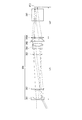
- FIG. 2 is a diagram illustrating the configuration of the projection optical device 36 and the back focus position BF1 of the convex lens 366 constituting a part of the projection optical device 36.
- the back focus position BF1 the back focus position of green light (position of the light modulation device 35G) is shown, and the polarization separation device 322 is omitted, and the illumination light is shown. It is described that each component is located on a straight line along the axis Ax.
- the projection optical device 36 has a function of projecting the combined light, which is image light reflected and incident by the polarization separation device 322, onto a projection surface (not shown). As shown in FIG.
- the projection optical device 36 includes a plurality of lenses 361, 362, 363, 364, and 365 accommodated in a lens barrel 360 (see FIG. 1), and the convex lens 366.
- the actual projection optical apparatus is not limited to six lenses, and may have more lenses.
- the light modulation devices 35R, 35G, and 35B are disposed at the back focus positions of the projection optical device 36, respectively. More specifically, each of the light modulation devices 35R, 35G, and 35B is disposed at the back focus position BF1 of the lens that is located closest to the light incident side among the plurality of lenses that form the projection optical device 36. Therefore, in this embodiment, the projection optical device 36 has a convex lens 366 positioned between the polarization separation device 322 and the dichroic prism 34 in addition to the lenses 361 to 365 in the lens barrel 360 in terms of lens design. Because of the configuration, each light modulation device 35 is arranged at the back focus position BF1 of the convex lens 366.
- FIG. 3 is a diagram showing a projection optical apparatus 36A as a comparative example of the projection optical apparatus 36 and a back focus position BF2 of the projection optical apparatus 36A.
- a projection optical apparatus 36A as a comparative example of the projection optical apparatus 36 will be described.
- the projection optical device 36A has a lens barrel 360 and lenses 361 to 365 and 366A, as in the case of the projection optical device 36. However, all of these lenses 361 to 365 and 366A are in the lens barrel 360.
- the storage is arranged. Among these, the lens 366A has the same function as the convex lens 366.
- the convex lens is designed for the projection optical device 36A in terms of lens design. Not included.
- the case where such a projection optical device 36A is employed is compared with the case where the projection optical device 36 according to the present embodiment is employed.
- the distance L12 (the distance L12 from the most convex lens 366 on the light incident side to the back focus position BF1 of the projection optical device 36 (lens 366)) that is the back focus of the projection optical device 36 shown in FIG. 2 is the projection optical shown in FIG.
- the distance is shorter than the distance L22 (the distance L22 from the most incident lens 366A to the back focus position BF2 of the projection optical device 36A (lens 366A)) which is the back focus of the device 36A. Therefore, the distance L11 from the lens 361 located closest to the light exit side in the projection optical device 36 shown in FIG.
- the projection optical device 36 can be configured as a projection optical device that has a shorter back focus and a smaller dimension in the direction along the central axis than the projection optical device 36A as a comparative example.
- Table 1 shows an example of a lens constituting the projection optical device 36
- Table 2 shows an example of a lens constituting a projection optical device 36A as a comparative example.
- the lens with the number “4” has a radius of 49.5237, a surface separation of 39.763257, and an effective radius of 10.1706619.
- the lens with surface number “4” has a radius of 102.77722, a surface interval of 76.890274, and an effective radius of 15.868343. Yes.
- the surface interval of each lens can be made smaller (substantially halved) than the surface interval of each lens constituting the projection optical device 36A. Therefore, as described above, the projection optical device 36 can be configured as a projection optical device having a small size in the direction along the central axis.
- the lens having the surface number “1” has a radius of 121.69073, a surface interval of 1.734356, and an effective radius of 11.968877.
- the lens with the surface number “1” has a radius of 258.222177, a surface interval of 1.734469, and an effective radius of 16.566122. Yes.
- the radius of each lens can be made smaller (approximately half) than the radius of each lens constituting the projection optical device 36A. Therefore, the projection optical device 36 can be configured as a projection optical device that is reduced in size in the radial direction of each lens.
- the projector 1 of this embodiment has the following effects.
- a convex lens 366 that is at least one of a plurality of lenses 361 to 366 constituting the projection optical device 36 is disposed between the polarization separation device 322 and the dichroic prism 34. According to this, the convex lens 366 becomes the most light incident side lens in the projection optical device 36, and the light modulation device 35 (35R, 35G, 35B) can be arranged at the back focus position of the convex lens 366.
- the distance between the convex lens 366 and the light modulation device 35 (35R, 35G, 35B) can be shortened as compared with the configuration described in Patent Document 1, the dimension along the central axis of the projection optical device 36 can be reduced. . Therefore, the projector 1 can be reduced in size.
- the convex lens 366 disposed between the illumination device 31 and the dichroic prism 34 Since the convex lens 366 disposed between the illumination device 31 and the dichroic prism 34 is disposed, the light that has passed through the polarization separation device 322 passes through the convex lens 366 and is incident on the dichroic prism 34. Can be parallelized. Accordingly, it is possible to suppress the spread of the light incident on the incident / exit surface 3411, and the light can be reliably incident on the light modulation device 35 (35R, 35G, 35B), so that the light utilization efficiency can be increased. . Further, the light emitted from the incident / exit surface 3411 can be collected and incident on other lenses 361 to 365 constituting the projection optical device 36. Furthermore, since the light modulation device 35 (35R, 35G, 35B) is constituted by a liquid crystal panel, the contrast can be improved by making each color light incident on the dichroic prism 34 in parallel.
- the light emitted from the light source device 31A of the illumination device 31 can be converted into p-polarized light by the polarization conversion element 318, and the p-polarized light (first polarization) can be reliably incident on the polarization separation device 322. Use efficiency can be increased.
- the plurality of color lights (red light, green light, and blue light) incident on the dichroic prism 34 are reliably transmitted by the plurality of prisms (first to third prisms 341 to 343) and the first and second color separation layers 344 and 345.
- the separated color lights can be incident on the light modulation devices 35 (35R, 35G, 35B) corresponding to the respective color lights. Further, since each color light can be separated and combined by one dichroic prism 34, the projector 1 can be miniaturized.
- the dichroic prism 34 is configured by a so-called gapless prism, and the red light R reflected by the first color separation layer 344 is totally reflected by the incident / exit surface 3411 of the first prism 341, and the corresponding light modulation device. Guided to 35R. Further, the blue light B reflected by the second color separation layer 345 passes through the second prism 342, is guided to the corresponding light modulation device 35B, and is transmitted through the second color separation layer 345. G passes through the third prism 343 and is guided to the corresponding light modulation device 35G.
- the dichroic prism 34 does not require a gap that is required when it is configured by a so-called Philips prism.
- the polarization beam splitter 322 is a plate-type PBS, aberration may occur when modulated light (second polarized light) passes through the tilted plate.
- the polarization separation device 322 is made p-polarization ( The occurrence of the aberration can be suppressed compared to the case where the first polarized light) is transmitted.
- the dichroic prism 34 is constituted by a so-called gapless prism.
- the present invention is not limited to this.
- the dichroic prism 34 may be configured by a Philips prism.
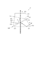
- FIG. 4 is a schematic diagram showing a dichroic prism 37 composed of a Philips prism.
- the dichroic prism 37 composed of the Philips prism is similar to the dichroic prism 34 composed of the gapless prism, as shown in FIG. 4, and the first color 371, the second prism 372, the third prism 373, and the first color.
- a separation layer 374 and a second color separation layer 375, and the prisms 371 to 373 are combined.
- the first prism 371 is formed in a substantially triangular prism shape, and is disposed at a position closest to the polarization separation device 322 among the first to third prisms 371 to 373.
- the first prism 371 has an incident / exit surface 3711 orthogonal to the illumination optical axis Ax, and light that has passed through the polarization separation device 322 enters the first prism 371 through the incident / exit surface 3711.
- a first color separation layer 374 is disposed between the first prism 371 and the second prism 372 joined to the first prism 371 so as to be inclined with respect to the illumination optical axis Ax. Yes. Specifically, the first color separation layer 374 is formed on the surface of the first prism 371 opposite to the incident / exit surface 3711.
- the first color separation layer 374 reflects light of a predetermined threshold value or more and transmits light of other wavelengths. For example, when the first color separation layer 374 is configured to reflect the blue light B and transmit the green light G and the red light R out of the incident light, the first color separation layer 374 reflects the first light.
- the blue light B is incident on the incident / exit surface 3711 from the inside of the first prism 371 at an angle greater than the critical angle. Then, the blue light B is incident from the emission surface 3712 of the first prism 371 to the blue light light modulation device 35B (not shown) facing the emission surface 3712.
- the green light G and the red light R incident on the first color separation layer 374 pass through the first color separation layer 374 and are further formed between the first prism 371 and the second prism 372. It passes through the gap GP and enters the second prism 372.
- the second prism 372 is formed in a substantially triangular prism shape, and is disposed between the first prism 371 and a gap GP of about several ⁇ m.
- a second color separation layer 375 is disposed between the second prism 372 and the third prism 373 so as to be inclined to the opposite side of the first color separation layer 374 with respect to the illumination optical axis Ax. ing. Similar to the second color separation layer 345, the second color separation layer 375 has a threshold value different from or different from that of the first color separation layer 374 out of light incident from the first prism 371 through the gap GP. Reflects light and transmits light of other wavelengths.
- the second color separation layer 375 when the second color separation layer 375 is configured to reflect the red light R and transmit the green light G out of the incident green light G and red light R, the second color separation layer 375.
- the red light R reflected by the light enters the end surface 3721 facing the first prism 371 from the inside of the second prism 372 at an angle greater than the critical angle.
- the red light R enters the light modulation device 35R (not shown) for red light that faces the emission surface 3722 from the emission surface 3722 of the second prism 372.
- the green light G that has passed through the second color separation layer 375 enters the third prism 373 that is joined to the second prism 372 without any gap.
- the third prism 373 is formed in a quadrangular prism shape with a substantially trapezoidal cross section.
- the third prism 373 has an exit surface 3731 parallel to the incident / exit surface 3711, that is, an exit surface 3731 orthogonal to the illumination optical axis Ax, on the side opposite to the surface on which light is incident from the second prism 372. .
- the green light G incident on the third prism 373 enters the light modulator 35G (not shown) for green light facing the emission surface 3731 from the emission surface 3731.
- the color lights B, G, R modulated by the light modulation devices 35B, 35G, 35R follow the incident paths of the color lights B, G, R to the light modulation devices 35B, 35G, 35R in reverse. And is emitted from the incident / exit surface 3711 toward the polarization separation device 322 as synthesized light.
- the first color separation layer 374 and the second color separation layer 375 intersect the illumination optical axis Ax at different angles, respectively, and light of each color separation layer 374, 375 is transmitted.
- the incident angles are also different.
- the first color separation layer 374 is inclined so that the incident angle of light incident along the illumination optical axis Ax is ⁇ 28 °
- the second color separation layer 375 It is inclined so that the incident angle of light incident along the optical axis Ax is + 11 °.
- the first color separation layer 374 and the second color separation layer are formed as in the case where the dichroic prism 34 composed of a gapless prism is employed.
- 375 has different color separation characteristics for each type of incident linearly polarized light.
- the incident angle of light to each of the color separation layers 374 and 375 and the illumination device 31 (specifically, a light source device) used in the projector.
- the same effect as the projector 1 can be obtained. .
- the dichroic prism 37 constituted by the Philips prism, it is necessary to dispose the gap GP of about several ⁇ m, but the light reflected by the second color separation layer 375 is reflected by the second prism 372. Since the inner surface is reflected by the surface facing one prism 371 and guided to the corresponding light modulation device 35, the incident angle of the light incident on the color separation layer is determined in the dichroic prism 34 formed by the gapless prism. The incident angle to the large second color separation layer 345 can be reduced. Therefore, the dichroic prism 37 has better color separation characteristics than the dichroic prism 34. On the other hand, the dichroic prism 34 does not require adjustment of the gap GP required by the dichroic prism 37 as described above.
- the dichroic prism 34 is constituted by a so-called gapless prism.
- the present invention is not limited to this.
- the dichroic prism 34 may be configured by a cross dichroic prism.
- the lens located closest to the light incident side of the projection optical device 36 is configured by the convex lens 366.
- the present invention is not limited to this.
- a concave lens may be used. Even in this case, since the distance L12 can be reduced, the distance L11 (dimension) in the direction along the central axis of the light emitted from the light source device of the projection optical device 36 can be reduced.
- the reflection type light modulation device 35 (35R, 35G, 35B) is used as the light modulation device, and the light separated by the dichroic prism 34 is modulated and reflected.
- the present invention is not limited to this.
- a transmission type light modulation device may be used instead of the light modulation device 35 (35R, 35G, 35B).
- a configuration that transmits the transmissive light modulator and emits the modulated light again to the dichroic prism 34 may be provided in the vicinity of the transmissive light modulator.
- the solid-state light source device 311 of the illumination device 31 is configured by a laser light source that emits blue light.
- the present invention is not limited to this.
- it is good also as replacing with the solid light source device 311 of the illuminating device 31, and providing a light source lamp and a reflector.
- the light emitted from the light source lamp and the reflector includes red, green, and blue, the rotating fluorescent plate 313 and the motor 314 need not be provided.
- the optical unit 3 was comprised by the substantially L shape, this invention is not limited to this.
- the projector 1 includes the three light modulation devices 35 (35R, 35G, and 35B), but the present invention is not limited to this. That is, the present invention can also be applied to a projector using two or less or four or more light modulation devices.
- the light modulation device can modulate an incident light beam and form an image according to image information
- a device using a micromirror for example, a device using a DMD (Digital Micromirror Device) or the like can be used.
- a light modulation device may be used.
Landscapes
- Physics & Mathematics (AREA)
- General Physics & Mathematics (AREA)
- Nonlinear Science (AREA)
- Optics & Photonics (AREA)
- Chemical & Material Sciences (AREA)
- Crystallography & Structural Chemistry (AREA)
- Projection Apparatus (AREA)
- Lenses (AREA)
- Liquid Crystal (AREA)
Abstract
L'invention concerne un projecteur susceptible d'obtenir une réduction de taille. Le projecteur (1) de l'invention possède : un dispositif d'éclairage destiné à émettre une première lumière polarisée ; une pluralité de dispositifs de modulation de lumière qui modulent chacune d'une pluralité de lumières colorées incluses dans la lumière émise ; un dispositif de séparation/synthèse de couleurs qui est disposé entre le dispositif d'éclairage et la pluralité de dispositifs de modulation de lumière, sépare la pluralité de lumières colorées de la lumière émise incidente sur l'intérieur par l'intermédiaire d'une surface d'émission/entrée, amène la pluralité de lumières colorées à devenir incidentes sur chacun de la pluralité de dispositifs de modulation de lumière et émet, par l'intermédiaire de la surface d'émission/entrée, une lumière synthétisée obtenue par synthèse de la pluralité de lumières colorées incidentes sur celle-ci qui ont été modulées par la pluralité de dispositifs de modulation de lumière ; un dispositif de séparation de lumière polarisée qui est disposé entre le dispositif d'éclairage et le dispositif de séparation/synthèse de couleurs, transmet une lumière parmi la première lumière polarisée et une seconde lumière polarisée orthogonale à la première lumière polarisée et réfléchit l'autre ; et un dispositif optique de projection destiné à projeter la lumière synthétisée émise par le dispositif de séparation de lumière polarisée. Le dispositif optique de projection possède une pluralité de lentilles. Au moins une lentille parmi la pluralité de lentilles est disposée entre le dispositif d'éclairage et le dispositif de séparation/synthèse de couleurs.
Applications Claiming Priority (2)
| Application Number | Priority Date | Filing Date | Title |
|---|---|---|---|
| JP2015-050508 | 2015-03-13 | ||
| JP2015050508A JP2016170302A (ja) | 2015-03-13 | 2015-03-13 | プロジェクター |
Publications (1)
| Publication Number | Publication Date |
|---|---|
| WO2016147580A1 true WO2016147580A1 (fr) | 2016-09-22 |
Family
ID=56920182
Family Applications (1)
| Application Number | Title | Priority Date | Filing Date |
|---|---|---|---|
| PCT/JP2016/001089 Ceased WO2016147580A1 (fr) | 2015-03-13 | 2016-03-01 | Projecteur |
Country Status (2)
| Country | Link |
|---|---|
| JP (1) | JP2016170302A (fr) |
| WO (1) | WO2016147580A1 (fr) |
Cited By (1)
| Publication number | Priority date | Publication date | Assignee | Title |
|---|---|---|---|---|
| WO2024034166A1 (fr) * | 2022-08-10 | 2024-02-15 | アルプスアルパイン株式会社 | Dispositif optique |
Families Citing this family (2)
| Publication number | Priority date | Publication date | Assignee | Title |
|---|---|---|---|---|
| JP7140575B2 (ja) * | 2018-07-12 | 2022-09-21 | キヤノン株式会社 | 色分離合成系およびこれを備える画像投射装置 |
| US20240085715A1 (en) * | 2021-04-30 | 2024-03-14 | Mgi Tech Co., Ltd. | Field-of-view stitching system and method, biological sample identification device and method |
Citations (6)
| Publication number | Priority date | Publication date | Assignee | Title |
|---|---|---|---|---|
| JPH04326315A (ja) * | 1991-04-26 | 1992-11-16 | Canon Inc | 投射光学系及びそれを有する光学機器 |
| JPH10319344A (ja) * | 1997-05-19 | 1998-12-04 | Matsushita Electric Ind Co Ltd | 投写型表示装置 |
| JP2003202629A (ja) * | 2001-11-05 | 2003-07-18 | Sharp Corp | プロジェクション光学装置 |
| WO2007015389A1 (fr) * | 2005-08-04 | 2007-02-08 | Matsushita Electric Industrial Co., Ltd. | Éclairage et dispositif d'affichage de projection l’employant |
| JP2012155004A (ja) * | 2011-01-24 | 2012-08-16 | Seiko Epson Corp | 照明装置およびプロジェクター |
| JP2013511066A (ja) * | 2009-11-11 | 2013-03-28 | イーストマン コダック カンパニー | 位相補償型薄膜ビームコンバイナ |
-
2015
- 2015-03-13 JP JP2015050508A patent/JP2016170302A/ja active Pending
-
2016
- 2016-03-01 WO PCT/JP2016/001089 patent/WO2016147580A1/fr not_active Ceased
Patent Citations (6)
| Publication number | Priority date | Publication date | Assignee | Title |
|---|---|---|---|---|
| JPH04326315A (ja) * | 1991-04-26 | 1992-11-16 | Canon Inc | 投射光学系及びそれを有する光学機器 |
| JPH10319344A (ja) * | 1997-05-19 | 1998-12-04 | Matsushita Electric Ind Co Ltd | 投写型表示装置 |
| JP2003202629A (ja) * | 2001-11-05 | 2003-07-18 | Sharp Corp | プロジェクション光学装置 |
| WO2007015389A1 (fr) * | 2005-08-04 | 2007-02-08 | Matsushita Electric Industrial Co., Ltd. | Éclairage et dispositif d'affichage de projection l’employant |
| JP2013511066A (ja) * | 2009-11-11 | 2013-03-28 | イーストマン コダック カンパニー | 位相補償型薄膜ビームコンバイナ |
| JP2012155004A (ja) * | 2011-01-24 | 2012-08-16 | Seiko Epson Corp | 照明装置およびプロジェクター |
Cited By (1)
| Publication number | Priority date | Publication date | Assignee | Title |
|---|---|---|---|---|
| WO2024034166A1 (fr) * | 2022-08-10 | 2024-02-15 | アルプスアルパイン株式会社 | Dispositif optique |
Also Published As
| Publication number | Publication date |
|---|---|
| JP2016170302A (ja) | 2016-09-23 |
Similar Documents
| Publication | Publication Date | Title |
|---|---|---|
| US10904498B2 (en) | Light source apparatus, projector, and light source module | |
| CN103430093B (zh) | 包括荧光体的照明光学系统和投影仪 | |
| CN110476010B (zh) | 照明装置以及投影仪 | |
| US20130194552A1 (en) | Lighting device and projection-type display device using same | |
| JP4514440B2 (ja) | 投写型映像表示装置 | |
| US10599025B2 (en) | Light source device and projector | |
| CN110632815A (zh) | 光源装置和投影仪 | |
| US10101647B2 (en) | Illuminator and projector | |
| JP7008177B2 (ja) | 投写型映像表示装置 | |
| JP2017083636A (ja) | 照明装置及びプロジェクター | |
| CN113433782A (zh) | 光源装置和投影仪 | |
| JP2020024318A (ja) | 光源装置およびプロジェクター | |
| CN112987470B (zh) | 光源装置和投影仪 | |
| JP7070620B2 (ja) | 光源装置およびプロジェクター | |
| WO2007141953A1 (fr) | Dispositif d'éclairage et dispositif d'affichage vidéo par projection l'utilisant | |
| US11156825B2 (en) | Projector | |
| JP7330787B2 (ja) | 光源装置およびこれを備える画像投射装置 | |
| JP2017015966A (ja) | 光源装置およびプロジェクター | |
| CN115128892B (zh) | 光源装置以及投影仪 | |
| JP2016170302A (ja) | プロジェクター | |
| JP2017146552A (ja) | 照明装置及びプロジェクター | |
| JP7188161B2 (ja) | プロジェクター | |
| JP7131177B2 (ja) | 光源装置およびプロジェクター | |
| US20230139540A1 (en) | Light source device and projector | |
| JP6701681B2 (ja) | 照明装置及びプロジェクター |
Legal Events
| Date | Code | Title | Description |
|---|---|---|---|
| 121 | Ep: the epo has been informed by wipo that ep was designated in this application |
Ref document number: 16764413 Country of ref document: EP Kind code of ref document: A1 |
|
| NENP | Non-entry into the national phase |
Ref country code: DE |
|
| 122 | Ep: pct application non-entry in european phase |
Ref document number: 16764413 Country of ref document: EP Kind code of ref document: A1 |