WO2016147625A1 - Appareil de traitement de signal, procédé de traitement de signal, et programme de capture d'image - Google Patents
Appareil de traitement de signal, procédé de traitement de signal, et programme de capture d'image Download PDFInfo
- Publication number
- WO2016147625A1 WO2016147625A1 PCT/JP2016/001343 JP2016001343W WO2016147625A1 WO 2016147625 A1 WO2016147625 A1 WO 2016147625A1 JP 2016001343 W JP2016001343 W JP 2016001343W WO 2016147625 A1 WO2016147625 A1 WO 2016147625A1
- Authority
- WO
- WIPO (PCT)
- Prior art keywords
- video signal
- luminance
- oetf
- conversion
- signal
- Prior art date
- Legal status (The legal status is an assumption and is not a legal conclusion. Google has not performed a legal analysis and makes no representation as to the accuracy of the status listed.)
- Ceased
Links
Images



Classifications
-
- H—ELECTRICITY
- H04—ELECTRIC COMMUNICATION TECHNIQUE
- H04N—PICTORIAL COMMUNICATION, e.g. TELEVISION
- H04N5/00—Details of television systems
- H04N5/14—Picture signal circuitry for video frequency region
- H04N5/20—Circuitry for controlling amplitude response
-
- H—ELECTRICITY
- H04—ELECTRIC COMMUNICATION TECHNIQUE
- H04N—PICTORIAL COMMUNICATION, e.g. TELEVISION
- H04N23/00—Cameras or camera modules comprising electronic image sensors; Control thereof
- H04N23/70—Circuitry for compensating brightness variation in the scene
- H04N23/72—Combination of two or more compensation controls
-
- G—PHYSICS
- G06—COMPUTING OR CALCULATING; COUNTING
- G06T—IMAGE DATA PROCESSING OR GENERATION, IN GENERAL
- G06T5/00—Image enhancement or restoration
- G06T5/90—Dynamic range modification of images or parts thereof
- G06T5/92—Dynamic range modification of images or parts thereof based on global image properties
-
- H—ELECTRICITY
- H04—ELECTRIC COMMUNICATION TECHNIQUE
- H04N—PICTORIAL COMMUNICATION, e.g. TELEVISION
- H04N23/00—Cameras or camera modules comprising electronic image sensors; Control thereof
- H04N23/60—Control of cameras or camera modules
- H04N23/63—Control of cameras or camera modules by using electronic viewfinders
Definitions
- the present invention relates to signal processing for a video signal, and more particularly, to signal processing for processing a high dynamic range video signal.
- a display device such as a video display or a projector has enabled higher luminance and higher dynamic range video display than those in a conventional cathode ray tube (CRT) display.
- CRT master monitor in the conventional CRT display has performed display with a luminance of 100 nit (cd/m 2 ) for 100 % white of a video signal
- the current display device can generally perform display with a luminance of 100 nit or more.
- a display device referred to as a High Dynamic Range (HDR) display has also appeared, which can perform display with a luminance of 1000 to 4000 nit.
- HDR High Dynamic Range
- an HDR EOTF capable of representing an HDR signal range by expanding an Electro-Optical Transfer Function (EOTF) corresponding to a display gamma defined for a conventional Standard Dynamic Range (SDR) display has been required.
- EOTF Electro-Optical Transfer Function
- an HDR EOTF to which a Perceptual Quantizer (PQ) having a visually optimum quantization accuracy is applied has been standardized for a display luminance range up to 10000 nit which is wider than a conventional range.
- the EOTF represented by the PQ is an absolute luminance EOTF because it is defined as a quantization value for an absolute luminance at a video output of the display device.
- a characteristic of an image capturing apparatus corresponding to a camera gamma of a video camera generally shows a property, which approximates a reverse characteristic of a display EOTF or to which a total gamma of a system is added, and which is referred to as an Optical-Electro Transfer Function (OETF).
- the OETF standardized in BT.709 is an SDR OETF optimized for the above described CRT master monitor having a luminance of 100 nit.
- a system gamma becomes 1.2 when combined with BT.1886 standardized as an EOTF for a flat panel display.
- a conventional camera-type OETF is a relative luminance OETF allocated to a sensor output value, which varies depending on dimming using a diaphragm or a filter in a lens optical system, a shutter speed, and a gain setting of a sensor circuit with a sensor output for an object having a standard reflectance as a predetermined reference value.
- Correct exposure is generally determined with an output value of a standard white object or a 18 % gray object as a reference in BT.709, for example.
- the above described SDR OETF has been problem-free in a situation where the dynamic range of the display device is narrow.
- the SDR OETF needs to be output as an HDR OETF by predetermined conversion.
- an OETF of an image capturing apparatus including a Log gamma is a relative luminance OETF, as described above.
- a criterion for converting a relative luminance into an absolute luminance is required.
- a method for image capturing purposely under exposure amount control has been generally used to place a high luminance object within a signal range and maintain a desired optical diaphragm value and shutter speed.
- a conversion criterion from a relative luminance OETF to an absolute luminance OETF needs to be changed depending on an image capturing situation. If video data to be recorded or transmitted has an original relative luminance OETF, therefore, in order to reproduce the brightness obtained at the time of the monitoring and replay the video image, the brightness during the reproduction needs to match a brightness in the absolute luminance EOTF at which the video signal has been monitored.
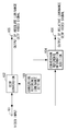
- Fig. 1 is a schematic configuration diagram of a video signal processing apparatus according to a first exemplary embodiment of the present invention.
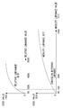
- Fig. 2 is a schematic view of conversion from a relative luminance OETF to an absolute luminance OETF.
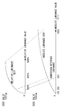
- Fig. 3 is a schematic view of conversion from a relative luminance OETF to an absolute luminance OETF.
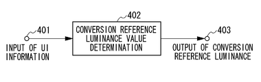
- Fig. 4 illustrates a configuration example of a conversion reference luminance setting circuit in a first exemplary embodiment.
- Fig. 5 is a schematic configuration diagram of a video signal processing apparatus according to a second exemplary embodiment.
- Fig. 6 is a schematic configuration diagram of a video signal processing apparatus according to a third exemplary embodiment.
- Fig. 1 is a schematic configuration diagram of a video signal processing apparatus according to a first exemplary embodiment of the present invention.
- Fig. 2 is a schematic view of conversion from a relative luminance OETF to an absolute luminance OETF.
- Fig. 3 is a schematic view of conversion from
- FIG. 7 is a schematic configuration diagram of a video signal processing apparatus according to a fourth exemplary embodiment.
- Fig. 8 is a schematic configuration diagram of a video signal processing apparatus according to a fifth exemplary embodiment.
- Fig. 9 is a schematic configuration diagram of a video signal processing apparatus according to a sixth exemplary embodiment.
- Fig. 10 is a schematic configuration diagram of an image capturing apparatus according to a seventh exemplary embodiment.
- Fig. 1 is a schematic configuration diagram of a video signal processing apparatus according to a first exemplary embodiment of the present invention.
- a video signal (first video signal), representing a video image with a relative luminance and quantized according to a relative luminance OETF, is input to a video input of a terminal 101.
- Examples of the video signal (first video signal) quantized according to the relative luminance OETF include a luminance linear signal obtained by subjecting an output of a video sensor serving as an image capturing unit to analog-to-digital (A/D) conversion and performing matrix calculation for mapping the output into a predetermined color space, a video signal quantized according to a gamma curve standardized in BT.709, and a Log video signal quantized according to a Log gamma curve having a dynamic range more expanded than that of the gamma curve standardized in BT.709.
- A/D analog-to-digital
- the present invention will be described using an example of a Log gamma having a dynamic range up to 800 % as the relative luminance OETF.
- the Log gamma is a relative luminance OETF having a dynamic range eight times higher than 100 %.
- An OETF conversion circuit 102 is a signal conversion unit, and converts the relative luminance OETF video signal (first video signal) into a video signal (second video signal).
- the second video signal is quantized according to an absolute luminance OETF to represent the relative luminance OETF video signal (first video signal) with an absolute luminance in an output of a display device for monitoring.
- a terminal 105 is a signal output unit, which outputs the video signal after the conversion.
- Examples of the absolute luminance OETF include a reverse characteristic of Perceptual Quantization (PQ) standardized in ST.2084.
- the PQ is an absolute luminance EOTF and is a quantization characteristic that is visually most efficient for an absolute luminance value of a pixel in displaying a video image.
- a video signal to be input to a display device having the input characteristic needs to be quantized according to the absolute luminance OETF having the reverse characteristic of the PQ.
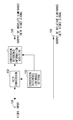
- Fig. 2 is a schematic view of a code mapping for converting a relative luminance OETF having a dynamic range up to 800 % into an absolute luminance OETF.
- a predetermined conversion reference luminance for conversion from the relative luminance to the absolute luminance is required as a correspondence relationship between video signals having the relative luminance and the absolute luminance.
- conversion is performed so that 100 % in the relative luminance OETF corresponds to 100 nit in the absolute luminance OETF.
- a conversion reference luminance is defined as an absolute luminance value corresponding to 100 % in the relative luminance OETF
- the conversion reference luminance in this case is 100 nit.
- a conversion reference luminance setting circuit 103 illustrated in Fig. 1 sets the conversion reference luminance for the OETF conversion circuit 102.
- 100 nit is set as the conversion reference luminance, and the conversion from the relative luminance OETF into the absolute luminance OETF is performed corresponding to the conversion reference luminance in the OETF conversion circuit 102.
- Fig. 3 is a schematic view of a code mapping when a conversion reference luminance is set to 400 nit.
- OETF conversion is performed so that 100 % in a relative luminance OETF corresponds to 400 nit in an absolute luminance OETF.
- an absolute luminance corresponding to 100 % in the relative luminance OETF is defined as a reference luminance in the above described example, the present invention is not limited to this.
- an absolute luminance corresponding to 200 % in the relative luminance OETF may be a reference luminance.
- the present invention may be based on definition other than the reference luminance. For example, another definition may be used as long as it represents a conversion correspondence from the relative luminance OETF to the absolute luminance OETF.
- a conversion reference information addition circuit 104 illustrated in Fig. 1 adds the conversion reference luminance set by the conversion reference luminance setting circuit 103, to the relative luminance OETF video signal (first video signal) as information representing a conversion correspondence (hereinafter referred to as conversion reference information) from the relative luminance OETF to the absolute luminance OETF.
- a terminal 106 is a signal output unit, which outputs a video signal with the conversion reference information added thereto.
- the conversion reference information may only be output in relation to a video file including a video signal.
- the present invention is not limited to the above described configuration for adding the conversion reference information to the video file as the meta data.
- the conversion reference information may only be output in association with the video file as needed for reference.
- Fig. 4 illustrates a configuration example of the conversion reference luminance setting circuit 103.
- User Interface (UI) information for selecting a conversion reference luminance is input from a terminal 401.
- a source of the UI information can be UI information through a menu operation of the video signal processing apparatus, UI information received in communication with an external device, or UI information to be selected according to a previously programmed procedure.
- the above described conversion reference luminance can be set using the conversion reference luminance setting circuit 103 as a unit for setting a conversion correspondence relationship.
- the conversion reference luminance setting circuit 103 may be provided in the external device communicating with the video signal processing apparatus to make a setting from the external device.
- a conversion reference luminance value determination circuit 402 decodes the above described UI information, and outputs the decoded UI information as the conversion reference luminance from a terminal 403.
- the video image can be displayed through output of the absolute luminance OETF by setting the conversion reference luminance from the relative luminance OETF to the absolute luminance OETF. Therefore, when conversion reference luminance information is used which is output in association with the video data, conversion into the same absolute luminance OETF can be carried out also in RAW development processing and post production.
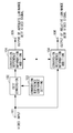
- Fig. 5 is a schematic configuration diagram of a video signal processing apparatus that adds conversion reference information to a video signal (second video signal) according to an absolute luminance OETF as a second exemplary embodiment of the present invention.
- the second exemplary embodiment is the same as the first exemplary embodiment except for the video signal to which the conversion reference information is to be added, and hence overlapping description is not repeated.
- a video signal (first video signal) quantized according to a relative luminance OETF is input to a video input of a terminal 101.
- An OETF conversion circuit 102 converts the relative luminance OETF video signal (first video signal) into an absolute luminance OETF video signal (second video signal).
- a conversion reference luminance setting circuit 103 sets a conversion reference luminance to the OETF conversion circuit 102.
- a conversion reference information addition circuit 104 adds the conversion reference luminance, which has been set by the conversion reference luminance setting circuit 103, to the absolute luminance OETF video signal (second video signal) as the conversion reference information.
- a terminal 105 outputs the video signal having the conversion reference information added thereto.
- a terminal 106 outputs the relative luminance OETF video signal (first video signal).
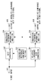
- Fig. 6 is a schematic configuration diagram of a video signal processing apparatus that adds conversion reference information to both a video signal (first video signal) according to a relative luminance OETF and a video signal (second video signal) according to an absolute luminance OETF as a third exemplary embodiment of the present invention.
- the third exemplary embodiment is the same as the first exemplary embodiment except for the video signals to which the conversion reference information is to be added, and hence overlapping description is not repeated.
- a relative luminance OETF video signal (first video signal) is input to a video input of a terminal 101.
- An OETF conversion circuit 102 converts the relative luminance OETF video signal (first video signal) into an absolute luminance OETF video signal (second video signal).
- a conversion reference luminance setting circuit 103 sets a conversion reference luminance to the OETF conversion circuit 102.
- a conversion reference information addition circuit 104 adds the conversion reference luminance, which has been set by the conversion reference luminance setting circuit 103, to both the relative luminance OETF video signal (first video signal) and the absolute luminance OETF video signal (second video signal) as the conversion reference information.
- Terminals 106 and 105 respectively output the video signals with the conversion reference information added thereto.
- Fig. 7 is a schematic configuration diagram of a video signal processing apparatus that converts a video signal (first video signal) quantized according to a first relative luminance OETF into a video signal (second video signal) quantized according to an absolute luminance OETF and converts into a video signal (third video signal) quantized according to a second relative luminance OETF.
- the video signal processing apparatus outputs the converted video signals, and adds conversion reference information to the second relative luminance OETF video signal (third video signal) as a fourth exemplary embodiment of the present invention.
- the present exemplary embodiment corresponds to a configuration in which a luminance linear signal obtained by subjecting an output of a video sensor serving as an image capturing unit to A/D conversion and performing color space matrix processing for the output, as described above, as the first relative luminance OETF video signal (first video signal).
- the obtained linear signal is directly converted into an absolute luminance OETF video signal while second relative luminance OETF conversion from the luminance linear signal to a Log gamma signal is performed.
- Such a configuration produces an effect of reducing degradation of accuracy caused by performing quantization characteristic conversion in multistage processes when the absolute luminance OETF video signal is generated.
- a video signal quantized according to a first relative luminance OETF (first video signal) is input to a video input of a terminal 101.
- An OETF conversion circuit 102 converts the video signal quantized according to the first relative luminance OETF (first video signal) into a video signal quantized according to an absolute luminance OETF video signal (second video signal), and outputs the converted video signal from a terminal 105.
- a conversion reference luminance setting circuit 103 sets a conversion reference luminance to the OETF conversion circuit 102.
- a relative luminance OETF conversion circuit 701 converts the first relative luminance OETF video signal (first video signal) input from the terminal 101, into a second relative luminance OETF video signal (third video signal).
- the first relative luminance OETF a luminance linear characteristic is conceivable
- the second relative luminance OETF BT.709 and a Log gamma characteristic are conceivable.
- a conversion reference information addition circuit 104 adds the conversion reference luminance set by the conversion reference luminance setting circuit 103, to the second relative luminance OETF video signal (third video signal) as conversion reference information, and outputs the video signal with the conversion reference information added thereto from a terminal 106.
- the conversion reference information added in the conversion reference information addition circuit 104 is a reference luminance in performing conversion from the first relative luminance OETF to the absolute luminance OETF in the OETF conversion circuit 102.
- the relative luminance OETF conversion circuit 701 converts the first relative luminance OETF to the second relative luminance OETF, if respective relative luminance values in the first and second relative luminance OETFs before and after the conversion do not change, i.e., if a conversion gain between the OETFs is 1, a 100 % luminance in the first relative luminance OETF is a 100 % luminance in the second relative luminance OETF.
- a result of converting the second relative luminance OETF into the absolute luminance OETF based on the conversion reference information added in the conversion reference information addition circuit 104 becomes equal to a conversion result from the first relative luminance OETF to the absolute luminance OETF in the OETF conversion circuit 102.
- the absolute luminance OETF video signal (second video signal) can be reproduced, using the added conversion reference information, from the second relative luminance OETF video signal (third video signal) that has been output from the terminal 106.
- Fig. 8 is a schematic configuration diagram of a video signal processing apparatus according to a fifth exemplary embodiment of the present invention that converts a video signal (first video signal) quantized according to a first relative luminance OETF into a video signal (second video signal) quantized according to an absolute luminance OETF, and into a video signal (third video signal) quantized according to a second relative luminance OETF.
- the converted video signals are output, and the conversion reference information is added to the absolute luminance OETF video signal (second video signal).
- the fifth exemplary embodiment is the same as the fourth exemplary embodiment except that the video signal to which the conversion reference information is added is different, and hence overlapping description is not repeated.
- a video signal quantized according to the first relative luminance OETF (first video signal) is input to a video input of a terminal 101.
- An OETF conversion circuit 102 converts the video signal quantized according to the first relative luminance OETF (first video signal) into a video signal quantized according to absolute luminance OETF (second video signal).
- a conversion reference luminance setting circuit 103 sets a conversion reference luminance to the OETF conversion circuit 102.
- a relative luminance OETF conversion circuit 701 converts the first relative luminance OETF video signal (first video signal) input from the terminal 101, into a second relative luminance OETF video signal (third video signal), and outputs the converted video signal from a terminal 106.
- a conversion reference information addition circuit 104 adds the conversion reference luminance set by the conversion reference luminance setting circuit 103, to the absolute luminance OETF video signal (second video signal) as conversion reference information, and outputs the video signal with the conversion reference information added thereto from a terminal 105.
- Fig. 9 is a schematic configuration diagram of a video signal processing apparatus according to a sixth exemplary embodiment of the present invention that converts a video signal (first video signal) quantized according to a first relative luminance OETF into a video signal (second video signal) quantized according to an absolute luminance OETF, and into a video signal (third video signal) quantized according to a second relative luminance OETF.
- the converted video signals is output, and the conversion reference information is added to both the absolute luminance OETF video signal (second video signal) and the second relative luminance OETF video signal (third video signal).
- a video signal quantized according to the first relative luminance OETF (first video signal) is input to a video input of a terminal 101.
- An OETF conversion circuit 102 converts the video signal quantized according to the first relative luminance OETF (first video signal) into an absolute luminance OETF (second video signal).
- a conversion reference luminance setting circuit 103 sets a conversion reference luminance to the OETF conversion circuit 102.
- a relative luminance OETF conversion circuit 701 converts the video signal of first relative luminance OETF (first video signal) input from the terminal 101, into a video signal of second relative luminance OETF (third video signal).
- a conversion reference information addition circuit 104 adds the conversion reference luminance set by the conversion reference luminance setting circuit 103, to both the second relative luminance OETF video signal (third video signal) and the absolute luminance OETF video signal (second video signal) as conversion reference information.
- the video signals with the conversion reference information added thereto are output from terminals 106 and 105.
- Fig. 10 is a schematic configuration diagram of an image capturing apparatus having a function of outputting an absolute luminance OETF video image and a function of recording a relative luminance OETF video image, according to a seventh exemplary embodiment of the present invention.
- a camera optical system 1001 includes optical devices such as a lens, a diaphragm, and a shutter, and forms an optical image on an image sensor 1002.
- An image sensor 1002 converts the formed optical image into an electric signal.
- An analog signal processing circuit 1003 performs analog signal processing such as amplification processing on a video signal converted into an electric signal.
- An A/D conversion circuit 1004 converts the analog video signal into a digital signal.
- a camera signal processing circuit 1005 performs interpolation processing of an image sensor pixel array, color space matrix processing, and white balance processing on the digital signal obtained by the A/D conversion, and outputs the obtained digital signal as a digital video signal.
- a video output signal processing circuit 1006 performs color space processing and gray scale processing for outputting the digital video signal as a real time video signal.
- the video signal in this stage is a relative luminance OETF video signal (first video signal) according to an exposure setting determined by a camera optical system and gain setting in analog/digital signal processing.
- An OETF conversion circuit 102 converts the video signal quantized according to a relative luminance OETF (first video signal) into a video signal (second video signal) quantized according to an absolute luminance OETF, and outputs the converted video signal from a terminal 105.
- a conversion reference luminance setting circuit 103 sets a conversion reference luminance to the OETF conversion circuit 102.
- a video recording signal processing circuit 1007 performs coding processing and meta data addition processing for recording the relative luminance OETF video signal.
- a media recording circuit 1008 serving as a recording unit adds the conversion reference luminance fed from the conversion reference luminance setting circuit 103 as meta data representing conversion reference information to the coded relative luminance OETF video signal (first video signal), and records the obtained video signal with the conversion reference information added thereto on a recording media 1009.
- the image capturing apparatus using the video signal processing apparatus according to the above described first exemplary embodiment has been described as an example, the video signal processing apparatus may be replaced with the video signal processing apparatus according to any one of the second to sixth exemplary embodiments.
Landscapes
- Engineering & Computer Science (AREA)
- Multimedia (AREA)
- Signal Processing (AREA)
- Physics & Mathematics (AREA)
- General Physics & Mathematics (AREA)
- Theoretical Computer Science (AREA)
- Studio Devices (AREA)
Abstract
Priority Applications (4)
| Application Number | Priority Date | Filing Date | Title |
|---|---|---|---|
| EP16764457.4A EP3272112A4 (fr) | 2015-03-17 | 2016-03-10 | Appareil de traitement de signal, procédé de traitement de signal, et programme de capture d'image |
| US15/558,510 US10397487B2 (en) | 2015-03-17 | 2016-03-10 | Signal processing apparatus, signal processing method, and image capturing apparatus |
| KR1020177029804A KR101981161B1 (ko) | 2015-03-17 | 2016-03-10 | 신호 처리장치, 신호 처리방법 및 촬상장치 |
| CN201680019193.2A CN107409178B (zh) | 2015-03-17 | 2016-03-10 | 信号处理设备、信号处理方法和摄像设备 |
Applications Claiming Priority (2)
| Application Number | Priority Date | Filing Date | Title |
|---|---|---|---|
| JP2015-054063 | 2015-03-17 | ||
| JP2015054063A JP6463179B2 (ja) | 2015-03-17 | 2015-03-17 | 信号処理装置、信号処理方法および撮像装置 |
Publications (1)
| Publication Number | Publication Date |
|---|---|
| WO2016147625A1 true WO2016147625A1 (fr) | 2016-09-22 |
Family
ID=56918675
Family Applications (1)
| Application Number | Title | Priority Date | Filing Date |
|---|---|---|---|
| PCT/JP2016/001343 Ceased WO2016147625A1 (fr) | 2015-03-17 | 2016-03-10 | Appareil de traitement de signal, procédé de traitement de signal, et programme de capture d'image |
Country Status (6)
| Country | Link |
|---|---|
| US (1) | US10397487B2 (fr) |
| EP (1) | EP3272112A4 (fr) |
| JP (1) | JP6463179B2 (fr) |
| KR (1) | KR101981161B1 (fr) |
| CN (1) | CN107409178B (fr) |
| WO (1) | WO2016147625A1 (fr) |
Cited By (1)
| Publication number | Priority date | Publication date | Assignee | Title |
|---|---|---|---|---|
| US11711486B2 (en) * | 2018-06-18 | 2023-07-25 | Dolby Laboratories Licensing Corporation | Image capture method and systems to preserve apparent contrast of an image |
Families Citing this family (3)
| Publication number | Priority date | Publication date | Assignee | Title |
|---|---|---|---|---|
| JP6883971B2 (ja) * | 2016-10-24 | 2021-06-09 | キヤノン株式会社 | 画像処理装置及び画像処理方法、プログラム、並びに記憶媒体 |
| JP2019008478A (ja) | 2017-06-22 | 2019-01-17 | キヤノン株式会社 | 画像処理装置及び方法、画像投影装置、印刷装置、及び画像印刷投影システム |
| JP7720751B2 (ja) * | 2021-09-13 | 2025-08-08 | キヤノン株式会社 | 画像処理装置、撮像装置、制御方法、及びプログラム |
Citations (2)
| Publication number | Priority date | Publication date | Assignee | Title |
|---|---|---|---|---|
| WO2013046096A1 (fr) * | 2011-09-27 | 2013-04-04 | Koninklijke Philips Electronics N.V. | Appareil et procédé de transformation de gamme dynamique d'images |
| WO2014178286A1 (fr) * | 2013-04-30 | 2014-11-06 | ソニー株式会社 | Dispositif d'émission, procédé d'émission, dispositif de réception et procédé de réception |
Family Cites Families (11)
| Publication number | Priority date | Publication date | Assignee | Title |
|---|---|---|---|---|
| EP1662477A1 (fr) * | 2004-11-26 | 2006-05-31 | Barco N.V. | Essai ou calibrage des échelles de gris affichées |
| CN102354489B (zh) | 2008-05-08 | 2014-01-22 | 香港应用科技研究院有限公司 | 增强图像动态范围的方法和装置 |
| US8184112B2 (en) * | 2008-09-24 | 2012-05-22 | Global Oled Technology Llc | Increasing dynamic range of display output |
| US20140029665A1 (en) * | 2011-04-08 | 2014-01-30 | Koninklijke Philips N.V. | Video encoding and decoding |
| JP6009538B2 (ja) * | 2011-04-28 | 2016-10-19 | コーニンクレッカ フィリップス エヌ ヴェKoninklijke Philips N.V. | Hdr画像を符号化及び復号するための装置及び方法 |
| PL3627490T3 (pl) | 2011-05-10 | 2022-02-28 | Koninklijke Philips N.V. | Generowanie i przetwarzanie sygnału obrazu o wysokim zakresie dynamiki |
| CA3114379C (fr) * | 2011-12-06 | 2023-06-27 | Dolby Laboratories Licensing Corporation | Dispositif et procede destines a ameliorer un echange de donnees d'images base sur une non-linearite de luminance perceptuelle a travers differentes capacites d'affichage |
| US9042682B2 (en) * | 2012-05-23 | 2015-05-26 | Dolby Laboratories Licensing Corporation | Content creation using interpolation between content versions |
| CN104471939B (zh) * | 2012-07-13 | 2018-04-24 | 皇家飞利浦有限公司 | 改进的hdr图像编码和解码方法和设备 |
| PL2836983T3 (pl) * | 2012-10-08 | 2018-01-31 | Koninklijke Philips Nv | Przetwarzanie obrazu zmieniające luminancję z ograniczeniami barwy |
| CN103067671B (zh) | 2012-12-31 | 2015-09-23 | 华为技术有限公司 | 一种显示图像的方法及装置 |
-
2015
- 2015-03-17 JP JP2015054063A patent/JP6463179B2/ja active Active
-
2016
- 2016-03-10 WO PCT/JP2016/001343 patent/WO2016147625A1/fr not_active Ceased
- 2016-03-10 US US15/558,510 patent/US10397487B2/en active Active
- 2016-03-10 CN CN201680019193.2A patent/CN107409178B/zh active Active
- 2016-03-10 EP EP16764457.4A patent/EP3272112A4/fr not_active Withdrawn
- 2016-03-10 KR KR1020177029804A patent/KR101981161B1/ko active Active
Patent Citations (2)
| Publication number | Priority date | Publication date | Assignee | Title |
|---|---|---|---|---|
| WO2013046096A1 (fr) * | 2011-09-27 | 2013-04-04 | Koninklijke Philips Electronics N.V. | Appareil et procédé de transformation de gamme dynamique d'images |
| WO2014178286A1 (fr) * | 2013-04-30 | 2014-11-06 | ソニー株式会社 | Dispositif d'émission, procédé d'émission, dispositif de réception et procédé de réception |
Non-Patent Citations (1)
| Title |
|---|
| See also references of EP3272112A4 * |
Cited By (1)
| Publication number | Priority date | Publication date | Assignee | Title |
|---|---|---|---|---|
| US11711486B2 (en) * | 2018-06-18 | 2023-07-25 | Dolby Laboratories Licensing Corporation | Image capture method and systems to preserve apparent contrast of an image |
Also Published As
| Publication number | Publication date |
|---|---|
| CN107409178A (zh) | 2017-11-28 |
| JP2016174315A (ja) | 2016-09-29 |
| JP6463179B2 (ja) | 2019-01-30 |
| CN107409178B (zh) | 2020-03-10 |
| EP3272112A1 (fr) | 2018-01-24 |
| EP3272112A4 (fr) | 2018-08-29 |
| KR20170129218A (ko) | 2017-11-24 |
| KR101981161B1 (ko) | 2019-05-22 |
| US10397487B2 (en) | 2019-08-27 |
| US20180084174A1 (en) | 2018-03-22 |
Similar Documents
| Publication | Publication Date | Title |
|---|---|---|
| US10891722B2 (en) | Display method and display device | |
| EP3627490B1 (fr) | Génération et traitement de signaux d'images à haute gamme dynamique | |
| US10397487B2 (en) | Signal processing apparatus, signal processing method, and image capturing apparatus | |
| CN109417588B (zh) | 信号处理设备、信号处理方法、相机系统、视频系统和服务器 | |
| JP2021506157A5 (fr) | ||
| GB2526047A (en) | Method and apparatus for improved signal processing for high dynamic range | |
| US20170272686A1 (en) | Information processing apparatus and information processing method | |
| KR102575281B1 (ko) | 결함화소 정보 기록장치, 결함화소 보정장치 및 방법 | |
| JP2018013696A (ja) | 画像処理装置および表示装置 | |
| US10009588B2 (en) | Image processing apparatus and imaging apparatus | |
| US20150235618A1 (en) | Image processing apparatus capable of inputting image data | |
| US9894315B2 (en) | Image capturing apparatus, image processing apparatus and method, image processing system, and control method for image capturing apparatus | |
| US7760243B2 (en) | Imaging apparatus and method of processing image signal | |
| EP1441518B1 (fr) | Dispositif de correction de caracteristique | |
| US11080829B2 (en) | Control apparatus and control method | |
| US11765468B2 (en) | Image processing device and method thereof, imaging element, and imaging device | |
| KR20160125382A (ko) | 이미지/비디오 신호에 관련된 비트 스트림을 생성하기 위한 방법, 특정 정보 데이터를 포함하는 비트 스트림, 그와 같은 특정 정보 데이터를 획득하기 위한 방법 | |
| US11037527B2 (en) | Display apparatus and display method | |
| US9531956B2 (en) | Image display apparatus that adjusts pixel gradation values using a lower limit value and control method thereof | |
| JP2004040300A (ja) | 画像処理装置 | |
| US12401910B2 (en) | Image processing apparatus, image processing method, and image capture apparatus | |
| US20120154603A1 (en) | Image recording system and method of calibrating, compressing and decompressing image signal values | |
| JP7282536B2 (ja) | 画像処理装置、画像処理方法およびプログラム | |
| JP2015142275A (ja) | 画像処理装置、画像処理方法、表示装置、表示方法、及び、プログラム | |
| JP2019213095A (ja) | 画像処理装置、撮像装置、及び画像処理装置の制御方法 |
Legal Events
| Date | Code | Title | Description |
|---|---|---|---|
| 121 | Ep: the epo has been informed by wipo that ep was designated in this application |
Ref document number: 16764457 Country of ref document: EP Kind code of ref document: A1 |
|
| WWE | Wipo information: entry into national phase |
Ref document number: 15558510 Country of ref document: US |
|
| NENP | Non-entry into the national phase |
Ref country code: DE |
|
| REEP | Request for entry into the european phase |
Ref document number: 2016764457 Country of ref document: EP |
|
| ENP | Entry into the national phase |
Ref document number: 20177029804 Country of ref document: KR Kind code of ref document: A |