WO2016147697A1 - Dispositif d'affichage d'image d'endoscope, procédé d'affichage d'image d'endoscope, et programme d'affichage d'image d'endoscope - Google Patents
Dispositif d'affichage d'image d'endoscope, procédé d'affichage d'image d'endoscope, et programme d'affichage d'image d'endoscope Download PDFInfo
- Publication number
- WO2016147697A1 WO2016147697A1 PCT/JP2016/051845 JP2016051845W WO2016147697A1 WO 2016147697 A1 WO2016147697 A1 WO 2016147697A1 JP 2016051845 W JP2016051845 W JP 2016051845W WO 2016147697 A1 WO2016147697 A1 WO 2016147697A1
- Authority
- WO
- WIPO (PCT)
- Prior art keywords
- image display
- display area
- image
- displayed
- button
- Prior art date
- Legal status (The legal status is an assumption and is not a legal conclusion. Google has not performed a legal analysis and makes no representation as to the accuracy of the status listed.)
- Ceased
Links
Images


Classifications
-
- A—HUMAN NECESSITIES
- A61—MEDICAL OR VETERINARY SCIENCE; HYGIENE
- A61B—DIAGNOSIS; SURGERY; IDENTIFICATION
- A61B1/00—Instruments for performing medical examinations of the interior of cavities or tubes of the body by visual or photographical inspection, e.g. endoscopes; Illuminating arrangements therefor
- A61B1/00002—Operational features of endoscopes
- A61B1/00004—Operational features of endoscopes characterised by electronic signal processing
- A61B1/00009—Operational features of endoscopes characterised by electronic signal processing of image signals during a use of endoscope
-
- G—PHYSICS
- G06—COMPUTING OR CALCULATING; COUNTING
- G06T—IMAGE DATA PROCESSING OR GENERATION, IN GENERAL
- G06T7/00—Image analysis
- G06T7/50—Depth or shape recovery
- G06T7/55—Depth or shape recovery from multiple images
- G06T7/593—Depth or shape recovery from multiple images from stereo images
-
- H—ELECTRICITY
- H04—ELECTRIC COMMUNICATION TECHNIQUE
- H04N—PICTORIAL COMMUNICATION, e.g. TELEVISION
- H04N13/00—Stereoscopic video systems; Multi-view video systems; Details thereof
- H04N13/20—Image signal generators
- H04N13/204—Image signal generators using stereoscopic image cameras
- H04N13/239—Image signal generators using stereoscopic image cameras using two two-dimensional [2D] image sensors having a relative position equal to or related to the interocular distance
-
- H—ELECTRICITY
- H04—ELECTRIC COMMUNICATION TECHNIQUE
- H04N—PICTORIAL COMMUNICATION, e.g. TELEVISION
- H04N21/00—Selective content distribution, e.g. interactive television or video on demand [VOD]
- H04N21/40—Client devices specifically adapted for the reception of or interaction with content, e.g. set-top-box [STB]; Operations thereof
- H04N21/41—Structure of client; Structure of client peripherals
- H04N21/422—Input-only peripherals, i.e. input devices connected to specially adapted client devices, e.g. global positioning system [GPS]
- H04N21/42204—User interfaces specially adapted for controlling a client device through a remote control device; Remote control devices therefor
-
- H—ELECTRICITY
- H04—ELECTRIC COMMUNICATION TECHNIQUE
- H04N—PICTORIAL COMMUNICATION, e.g. TELEVISION
- H04N21/00—Selective content distribution, e.g. interactive television or video on demand [VOD]
- H04N21/40—Client devices specifically adapted for the reception of or interaction with content, e.g. set-top-box [STB]; Operations thereof
- H04N21/43—Processing of content or additional data, e.g. demultiplexing additional data from a digital video stream; Elementary client operations, e.g. monitoring of home network or synchronising decoder's clock; Client middleware
- H04N21/431—Generation of visual interfaces for content selection or interaction; Content or additional data rendering
- H04N21/4312—Generation of visual interfaces for content selection or interaction; Content or additional data rendering involving specific graphical features, e.g. screen layout, special fonts or colors, blinking icons, highlights or animations
- H04N21/4316—Generation of visual interfaces for content selection or interaction; Content or additional data rendering involving specific graphical features, e.g. screen layout, special fonts or colors, blinking icons, highlights or animations for displaying supplemental content in a region of the screen, e.g. an advertisement in a separate window
-
- H—ELECTRICITY
- H04—ELECTRIC COMMUNICATION TECHNIQUE
- H04N—PICTORIAL COMMUNICATION, e.g. TELEVISION
- H04N21/00—Selective content distribution, e.g. interactive television or video on demand [VOD]
- H04N21/40—Client devices specifically adapted for the reception of or interaction with content, e.g. set-top-box [STB]; Operations thereof
- H04N21/47—End-user applications
-
- H—ELECTRICITY
- H04—ELECTRIC COMMUNICATION TECHNIQUE
- H04N—PICTORIAL COMMUNICATION, e.g. TELEVISION
- H04N23/00—Cameras or camera modules comprising electronic image sensors; Control thereof
- H04N23/50—Constructional details
- H04N23/555—Constructional details for picking-up images in sites, inaccessible due to their dimensions or hazardous conditions, e.g. endoscopes or borescopes
-
- G—PHYSICS
- G06—COMPUTING OR CALCULATING; COUNTING
- G06T—IMAGE DATA PROCESSING OR GENERATION, IN GENERAL
- G06T2200/00—Indexing scheme for image data processing or generation, in general
- G06T2200/24—Indexing scheme for image data processing or generation, in general involving graphical user interfaces [GUIs]
-
- G—PHYSICS
- G06—COMPUTING OR CALCULATING; COUNTING
- G06T—IMAGE DATA PROCESSING OR GENERATION, IN GENERAL
- G06T2207/00—Indexing scheme for image analysis or image enhancement
- G06T2207/10—Image acquisition modality
- G06T2207/10004—Still image; Photographic image
- G06T2207/10012—Stereo images
-
- G—PHYSICS
- G06—COMPUTING OR CALCULATING; COUNTING
- G06T—IMAGE DATA PROCESSING OR GENERATION, IN GENERAL
- G06T2207/00—Indexing scheme for image analysis or image enhancement
- G06T2207/10—Image acquisition modality
- G06T2207/10068—Endoscopic image
-
- H—ELECTRICITY
- H04—ELECTRIC COMMUNICATION TECHNIQUE
- H04N—PICTORIAL COMMUNICATION, e.g. TELEVISION
- H04N13/00—Stereoscopic video systems; Multi-view video systems; Details thereof
- H04N13/30—Image reproducers
-
- H—ELECTRICITY
- H04—ELECTRIC COMMUNICATION TECHNIQUE
- H04N—PICTORIAL COMMUNICATION, e.g. TELEVISION
- H04N21/00—Selective content distribution, e.g. interactive television or video on demand [VOD]
- H04N21/40—Client devices specifically adapted for the reception of or interaction with content, e.g. set-top-box [STB]; Operations thereof
- H04N21/41—Structure of client; Structure of client peripherals
- H04N21/422—Input-only peripherals, i.e. input devices connected to specially adapted client devices, e.g. global positioning system [GPS]
- H04N21/42204—User interfaces specially adapted for controlling a client device through a remote control device; Remote control devices therefor
- H04N21/42206—User interfaces specially adapted for controlling a client device through a remote control device; Remote control devices therefor characterized by hardware details
- H04N21/4221—Dedicated function buttons, e.g. for the control of an EPG, subtitles, aspect ratio, picture-in-picture or teletext
-
- H—ELECTRICITY
- H04—ELECTRIC COMMUNICATION TECHNIQUE
- H04N—PICTORIAL COMMUNICATION, e.g. TELEVISION
- H04N21/00—Selective content distribution, e.g. interactive television or video on demand [VOD]
- H04N21/40—Client devices specifically adapted for the reception of or interaction with content, e.g. set-top-box [STB]; Operations thereof
- H04N21/41—Structure of client; Structure of client peripherals
- H04N21/422—Input-only peripherals, i.e. input devices connected to specially adapted client devices, e.g. global positioning system [GPS]
- H04N21/42204—User interfaces specially adapted for controlling a client device through a remote control device; Remote control devices therefor
- H04N21/42206—User interfaces specially adapted for controlling a client device through a remote control device; Remote control devices therefor characterized by hardware details
- H04N21/42224—Touch pad or touch panel provided on the remote control
Definitions
- the present invention relates to an endoscopic image display device, an endoscopic image display method, and an endoscopic image display program, and in particular, an endoscopic image display device that displays at least two endoscopic images, and an endoscopic image display.
- the present invention relates to a method and an endoscope image display program.
- endoscope apparatuses have been widely used in the industrial field and the medical field.
- an endoscope image of a subject obtained through an observation window provided at the distal end portion of the insertion portion is displayed on a monitor, and a user who is an examiner can inspect the subject while looking at the monitor. And can be recorded in a storage device.
- endoscope devices for example, an endoscope having a stereo measurement function.
- an endoscope apparatus having a stereo measurement function By using an endoscope apparatus having a stereo measurement function, it is possible to measure the distance from the distal end of the insertion portion to a designated point on the subject, or to measure the distance between two designated points on the subject.
- Japanese Unexamined Patent Application Publication No. 2006-226820 proposes a navigation device with a touch panel that can arbitrarily and freely change the scroll speed.
- a scroll speed designation icon as a speed mark is displayed on the screen, and the user touches the icon to give an instruction to change the scroll speed when scrolling the map to a desired speed. can do.
- endoscope devices are basically used for various examinations and various measurements, when specifying points on the subject displayed on the screen of the display device as measurement points, be careful with respect to operating devices such as joysticks. User operation is required.
- the change of the display range of the endoscopic image on the screen of the display device is realized by a zoom function or the like, but a joystick or the like is also used when the display range is changed accurately. Therefore, a complicated operation is required for the user.
- the display device with a touch panel described above can also be applied to an endoscope apparatus. Since a display device with a touch panel can easily select functions on the menu screen, the operability is good for the user.
- a mark such as a cursor is placed near the measurement point position.
- the present invention is capable of quickly specifying the position of a measurement point or the like in at least two or more endoscopic images or changing the display range of the endoscopic image displayed on the screen with a small number of operations.
- An object is to provide an endoscope image display device, an endoscope image display method, and an endoscope image display program.
- a display device having a first image display area and a second image display area for displaying an endoscopic image, the first image display area, and the second image
- a first operation instruction is received when the selection unit that selects any one of the display regions and the first image display region is selected by the selection unit, the first image display region and When the position of the mark displayed in the second image display area or the display range of the image is changed by a first change amount, and the second image display area is selected by the selection unit
- the second operation instruction is received, the position of the mark displayed in the first image display area and the second image display area or the display range of the image is different from the first change amount.
- a table that controls display so that it changes by the amount of change A control unit it is possible to provide an endoscope image display device having a.
- the first image display area and the second image display in a display device having a first image display area and a second image display area for displaying an endoscopic image.
- the first image display area and the second image display area are displayed.
- the first Display control is performed so that the position of the mark displayed in the image display area and the second image display area or the display range of the image is changed by a second change amount different from the first change amount.
- the first image display area and the second image display in a display device having a first image display area and a second image display area for displaying an endoscopic image.
- a program for displaying an area, the function for selecting one of the first image display area and the second image display area, and when the first image display area is selected In addition, when the first operation instruction is received, the position of the mark or the image display range displayed in the first image display area and the second image display area is changed in the first image display area.
- the second operation instruction is received when the second image display area is selected and the second image display area is selected, the second image display area and the first image display area and the second image display area are changed.
- the macro displayed in the second image display area An endoscope image display program for causing a computer to perform display control so as to change the position of the image or the display range of the image by a second change amount different from the first change amount. Can be provided.
- FIG. 1 is a block diagram showing a configuration of an endoscope apparatus according to a first embodiment of the present invention. It is a figure which shows the example of the stereo live image displayed on the display part 14 at the time of the stereo measurement mode concerning the 1st Embodiment of this invention. It is a figure which shows the other example of the stereo live image displayed on the display part 14 at the time of the stereo measurement mode concerning the 1st Embodiment of this invention. It is a figure which shows the other example of the stereo live image displayed on the display part 14 at the time of the stereo measurement mode concerning the 1st Embodiment of this invention.
- FIG. 1 is a block diagram showing a configuration of an endoscope apparatus according to the present embodiment.
- the endoscope apparatus 1 includes an endoscope 2 and an apparatus main body 3 to which the endoscope 2 is connected.
- the endoscope 2 is configured to be detachable from the apparatus main body 3.
- the endoscope 2 outputs an imaging signal of a subject obtained through an observation window provided at the distal end portion of the insertion portion to the apparatus main body 3.
- the endoscope apparatus 1 has a stereo measurement function in addition to a normal observation function. Therefore, the endoscope 2 has an insertion portion (not shown), and an optical adapter 4 to be used when performing stereo measurement is detachable from the distal end portion of the insertion portion.
- the optical adapter 4 has two observation windows, and gives two optical images of a subject having parallax to the imaging surface of the imaging device of the insertion portion of the endoscope 2.
- the optical adapter 4 has a contact (not shown) for enabling the endoscope 2 or the apparatus main body 3 to detect that the optical adapter 4 is attached to the distal end of the insertion portion of the endoscope 2. ing.
- the apparatus body 3 includes a camera control unit (hereinafter referred to as CCU) 11, a control unit 12, a video signal processing circuit 13, a display unit with a touch panel (hereinafter referred to as display unit) 14, an operation unit 15, and a LAN interface.
- CCU camera control unit
- control unit 12 a control unit 12
- video signal processing circuit 13 a display unit with a touch panel
- display unit 14 an operation unit 15, and a LAN interface.
- LAN I / F 16
- memory card interface hereinafter abbreviated as memory card I / F
- USB I / F USB interface
- audio signal processing circuit 19 And a speaker 20 and a microphone 21.
- the CCU 11 drives an imaging device (not shown) of the endoscope 2 under the control of the control unit 12, receives an imaging signal output from the imaging device, and outputs it to the video signal processing circuit 13.
- the control unit 12 receives signals from various circuits in the apparatus body 3 and outputs control signals to the various circuits.
- the control unit 12 includes a central processing unit (hereinafter referred to as CPU) 12a, a ROM 12b, and a RAM 12c.
- the various setting data includes cursor change amounts da and db, which will be described later.
- the change amounts da and db are amounts corresponding to the unit movement distance of the finger F when touching the LCD 14a (that is, the touch panel) in a drag operation or the like described later. That is, each change amount da, db is defined as a function of the moving distance of the finger F on the LCD 14a. Each change amount da, db may be defined as a function of the moving speed of the finger F on the LCD 14a.
- the control unit 12 can determine whether or not the optical adapter 4 is attached to the distal end of the insertion portion of the endoscope 2 based on the conduction state signal of the contact of the optical adapter 4 through the endoscope 2. .
- the video signal processing circuit 13 processes the imaging signal from the CCU 11 to generate an image signal and outputs it to the display unit 14.
- the video signal processing circuit 13 executes image processing according to various functions under the control of the control unit 12. When the stereo measurement function is executed, the video signal processing circuit 13 generates two endoscopic images having parallax and outputs them to the display unit 14. That is, the endoscope apparatus 1 is an endoscope image display apparatus.
- the display unit 14 includes a liquid crystal display (LCD) 14a and a touch panel 14b.
- the touch panel 14b is, for example, an electrostatic touch panel, and is provided in close contact with the display screen of the liquid crystal display 14a.
- a position signal from the touch panel 14 b is output to the control unit 12.
- the operation unit 15 includes a plurality of operation devices such as a freeze button, a release button, a joystick, a zoom operation button, and a menu button.
- the LAN I / F 16 is an interface for connection to a local area network (hereinafter referred to as LAN).
- the endoscope apparatus 1 can communicate with an external device connected to the LAN via the LAN I / F 16.
- the memory card I / F 17 is an interface for mounting a memory card as a storage medium.
- the endoscope apparatus 1 can record an endoscope image to a memory card and read data from the memory card via the memory card I / F 17.
- the USB I / F 18 is an interface for connecting a USB (Universal Serial Bus) cable or a USB device.
- the endoscope apparatus 1 can record an endoscopic image on a USB device and read data from the USB device via the USB I / F 18.
- the audio signal processing circuit 19 processes the audio signal from the control unit 12 under the control of the control unit 12, outputs audio from the speaker 20, and processes the audio signal from the microphone 21 to the control unit 12. Output.
- the endoscope apparatus 1 can record and reproduce audio along with the endoscopic image.
- a user who is an inspector can execute various functions of the endoscope apparatus 1 by operating the touch panel 14b or the operation unit 15.
- the control unit 12 reads a predetermined program from the ROM 12b in accordance with a command instructed on the touch panel 14b or the operation unit 15, and displays the endoscopic image on the LCD 14a by executing the program while using the RAM 12c as a work area. Or the obtained endoscopic image can be recorded on a memory card.
- the user attaches the optical adapter 4 to the distal end portion of the insertion portion of the endoscope 2, selects a desired command from the menu screen displayed on the screen of the LCD 14a, and instructs execution thereof. It is also possible to cause the mirror device 1 to execute a stereo measurement function.
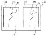
- FIG. 2A to 2C are diagrams illustrating examples of stereo live images displayed on the display unit 14 in the stereo measurement mode.
- a screen 31 in FIG. 2A is a graphical user interface (GUI) including two image display areas 32 and 33 on which a stereo live image is displayed.
- the screen 31 displayed on the LCD 14a has two image display areas for displaying two images of a left eye image and a right eye image. Therefore, the display unit 14 is a display device having a left image display area 32 and a right image display area 33 for displaying an endoscopic image.
- GUI graphical user interface
- the left image display area 32 displays a left eye image
- the right image display area 33 displays a right eye image.
- the endoscope 2 generates an imaging signal including left and right images by the optical adapter 4, and the apparatus body 3 generates a left eye image and a right eye image from the received imaging signal and displays them on the LCD 14a.
- the left image display area 32 and the right image display area 33 are displayed on one display unit of the LCD 14a of the display unit 14, but the left image display area 32 and the right image are displayed using two display devices.
- the display area 33 may be displayed on a separate display device.
- the left image display area 32 and the right image display area 33 need not have the same size.
- the left image display area 32 may be displayed larger on the screen 31, and the right image display area 33 may be displayed smaller as a confirmation image.
- the left image display area 32 and the right image display area 33 are rotated by 90 degrees, the left image display area 32 is enlarged to fit the screen 31, and the right image display area 33 is expanded. May be displayed on the left image display area 32 as a confirmation image.
- the user can specify measurement points in the stereo measurement mode. For example, a cursor as a mark for designating a measurement point is displayed on the screen, and the cursor is moved to a desired position by dragging with a finger on the touch panel 14b to designate the measurement point. it can.
- the user can move either the left eye image cursor 35 a displayed in the left image display area 32 or the right eye image cursor 35 b displayed in the right image display area 33.
- the cursor is moved by a drag operation in which the cursor to be moved on the left image display area 32 or the right image display area 33 is moved in a moving direction while being touched by the user after long pressing with a finger.
- the cursor is moved by, for example, specifying the cursor to be moved by double-tapping on the screen and then performing a swipe operation on the screen (that is, touching the screen with a finger without specifying the touched location)
- the operation may be performed by an operation such as an operation of moving the user in the direction in which the user wants to move) or a flick operation (an operation of moving quickly to play a short distance).
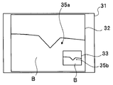
- cursors 35a and 35b which are marks for designating measurement points, are displayed in image display areas 32 and 33, respectively.
- a part of the blade B in the jet engine is displayed on the LCD 14a.
- the endoscopic image displayed in the left image display area 32 and the endoscopic image displayed in the right image display area 33 are left and right endoscopic images for stereo measurement, and are images having parallax with each other. .
- the position of the cursor 35a and the position of the cursor 35b are displayed at positions corresponding to the parallax between the two endoscopic images. Therefore, when the position of the cursor 35a in the left image display area 32 is moved, the position of the cursor 35b in the right image display area 33 is also moved, but the position of the cursor 35b is at the position on the subject indicated by the cursor 35a. The corresponding position on the right eye image is the position calculated by the matching process. Similarly, when the position of the cursor 35b in the right image display area 33 is moved, the position of the cursor 35a in the left image display area 32 is also moved, but the position of the cursor 35a is a position on the subject indicated by the cursor 35b. The position on the left eye image corresponding to is the position calculated by the matching process.
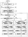
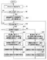
- FIG. 3 is a flowchart showing an example of the flow of cursor display processing in the stereo measurement mode.
- the processing of FIG. 3 is performed by the CPU 12a of the control unit 12 reading out and executing a cursor display processing program from the ROM 12b when the stereo measurement optical adapter 4 is attached to the distal end of the insertion unit.
- the control unit 12 outputs an instruction to the video signal processing circuit 13 to display a stereo live image as shown in FIGS. 2A to 2C on the LCD 14a (S1).
- control unit 12 determines whether or not the stereo measurement mode is set (S2).
- the setting of the stereo measurement mode is performed when the user selects the stereo measurement mode from the menu screen.
- the process returns to S1.
- the control unit 12 reads from the ROM 12b information on the change amount da of the cursor 35a for the left eye image and the change amount db of the cursor 35b for the right eye image.
- the control unit 12 determines whether or not a predetermined operation has been performed on the touch panel 14b (S4). If there is no predetermined operation on the touch panel 14b, the process returns to S1.
- the predetermined operation is a drag operation for moving the finger F after a long press. That is, it is determined whether a drag operation for moving the left eye image cursor 35a or the right eye image cursor 35b on the touch panel 14b while touching the finger F is performed.
- the control unit 12 determines whether the operation is performed on the left image display area 32 (S5).
- the processes of S4 and S5 constitute a selection unit that selects one of the left image display area 32 and the right image display area 33. That is, one of the left image display area 32 and the right image display area 33 is selected by touching the cursor 35a or 35b.
- selection of one of the left image display area 32 and the right image display area 33 may be performed by touching the selected image display area or by selecting on the menu screen. In that case, since either one of the left image display area 32 and the right image display area 33 is selected according to the touch on the image display area to be selected or the selection result on the menu screen, the image display area to be selected is selected.
- the touch detection process and the selection instruction input process using the menu screen and its joystick constitute a selection unit.
- the control unit 12 moves the cursor 35a (that is, the distance that the cursor 35a has moved by the drag operation on the display unit 14). Therefore, the cursor 35a for the left eye image is moved in the left image display area 32 based on the change amount da (S6).
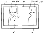
- FIG. 4 is a diagram showing a state where the user's finger F is touching the cursor 35a for the left eye image.
- the user performs a drag operation to move the cursor 35a for the left eye image in a direction in which the user wants to move from a state where the finger F is touching the touch panel 14b. Since the change in the position of the finger F in the drag operation is input to the control unit 12, the control unit 12 can calculate the amount of movement of the finger F in the drag operation.
- the control unit 12 moves the cursor 35a for the left eye image in the drag direction (direction indicated by the dotted line) in the left image display area 32 by an amount determined from the movement distance of the finger F based on the change amount da. Move with.
- the change amount da is set to 1 cm on the LCD 14a and the finger F is moved 1 cm on the LCD 14a
- the finger F is moved 1 cm on the LCD 14a
- the cursor 35a for the left eye image is Move 1 cm in the drag direction on the LCD 14a.
- the moved cursor 35a is defined as a cursor 35a '.
- the control unit 12 moves the right eye image cursor 35b within the right image display area 33 by a distance corresponding to the amount of movement of the left eye image cursor 35a (S7).
- the right eye image cursor 35b also moves in the right image display area 33 in the drag direction. Move 1 cm
- the moved cursor 35b is set as a cursor 35b '.
- the control unit 12 moves the right-eye image cursor 35b in the right-image display area 33, and then the right-image display area corresponding to the position of the left-eye image cursor 35a in the left-image display area 32.
- the position of the cursor 35b for the right eye image in 33 is recalculated by matching processing (S8).
- the recalculation of the position of the right eye image cursor 35b is performed after the right eye image cursor 35b is moved in the right image display area 33 (S7).
- the right eye image cursor 35b may be moved in the right image display area 33 while correcting the position of the right eye image cursor 35b by recalculation.
- control unit 12 redisplays the cursor 35b for the right eye image at the corrected position in the recalculated right image display area 33 (S9). After S9, the process returns to S4.
- the control unit 12 moves the movement amount of the cursor 35b for the right eye image (that is, the cursor 35b is dragged on the display unit 14).
- the cursor 35b for the right eye image is moved within the right image display area 33 based on the change amount db (S10).
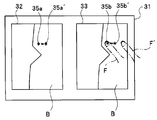
- FIG. 5 is a diagram illustrating a state where the user's finger F is touching the cursor 35b for the right eye image. The user performs a drag operation to move the right eye image cursor 35b in a direction in which the finger F is in contact with the touch panel 14b.
- the control unit 12 moves the cursor 35b for the right eye image in the drag direction (direction indicated by the dotted line) in the right image display area 33 by an amount determined from the movement distance of the finger F based on the change amount db. Move with.
- the change amount db is set to 0.1 cm on the LCD 14a and the finger F is moved 1 cm on the LCD 14a
- the cursor 35b for the right eye image Moves 0.1 cm in the drag direction on the LCD 14a.
- the moved cursor 35b is set as a cursor 35b '.
- the position of the finger F ′ after movement is different from the position of the cursor 35b ′ after movement.
- the control unit 12 moves the left-eye image cursor 35a within the left-image display area 32 by a distance corresponding to the movement amount of the right-eye image cursor 35b (S11).
- the left eye image cursor 35a also moves in the left image display area 32 in the drag direction. Move 0.1 cm.
- the moved cursor 35a is defined as a cursor 35a '.
- control unit 12 moves the left image display area corresponding to the position of the right eye image cursor 35b in the right image display area 33.
- the position of the cursor 35a for the left eye image within 32 is recalculated by matching processing (S12).
- the recalculation of the position of the cursor 35a for the left eye image is performed after moving the cursor 35a for the left eye image within the left image display area 32 (S11), but in S11, The left eye image cursor 35a may be moved in the left image display region 32 while correcting the position of the left eye image cursor 35a by recalculation.
- the control unit 12 redisplays the cursor 35a for the left eye image at the corrected position in the recalculated left image display area 32 (S13). After S13, the process returns to S4.
- the processing in FIG. 3 ends when the user instructs the end of the stereo measurement processing mode on the menu screen.
- the process is displayed in the left image display area 32 and the right image display area 33.
- the position of each of the cursors 35a and 35b as the mark being changed is changed by the change amount da and the right image display area 33 is selected, if a predetermined operation instruction is received by a drag operation, the left image display area 32 and A display control unit is configured to perform display control so that the positions of the cursors 35a and 35b as marks displayed in the right image display area 33 are changed by a change amount db different from the change amount da.
- the process of FIG. 3 is repeated so that the user moves the cursors 35a and 35b by touching the left image display area 32.
- the coarse movement for large movement and the fine movement for small movement of the cursors 35a and 35b so as to touch the inside of the right image display area 33 can be repeated one or more times. Therefore, the user can quickly and accurately move the cursors 35a and 35b to desired positions.
- FIG. 6 is a diagram for explaining the movement of the cursor. If the user wants to move the cursors 35a and 35b to the desired position P1, the user performs the above-described rough movement and fine movement several times by the above-described drag operation, thereby moving the cursors 35a and 35b to the desired position.
- the position P1 can be easily and quickly moved with a small number of operations.
- FIG. 7 is a diagram for explaining another example of the movement of the cursor.
- FIG. 7 shows a case where the cursor is moved in a desired direction while touching an arbitrary position on the screen.
- the cursors 35a and 35b move in the direction of the finger.
- the cursor 35 a moves in the direction of the finger F.
- the cursor 35a moves to the position of the finger F, it stops.
- the cursor 35a moves toward the destination where the finger F has moved. If the finger 35 is released while the cursor 35a is moving toward the finger F, the cursor 35a stops.
- the cursor 35b moves and stops in accordance with the movement and stop of the cursor 35a.
- the cursors 35a and 35b move coarsely
- the cursors 35a and 35b move finely.
- the change amount da for the left image display area 32 touched by the finger F or the right image display area first is kept away from the touch panel 14b and the drag operation is continuously performed.
- the change amount db for 33 the cursors 35a and 35b are moved even if the image display area first touched by the finger F is exceeded. That is, when the operation is performed beyond the image display area touched by the finger F first, the value of the amount of change for the image display area first touched by the finger F is continuously used to change the cursors 35a and 35b. Move.
- the cursor 35a continues.
- the position of the cursor is continuously changed.
- the position of 35b may be changed based on the change amount db.
- an endoscopic image display device that can quickly specify the position of a measurement point or the like in at least two or more endoscopic images with a small number of operations is provided. be able to.
- the cursor is moved on one of the two image display areas on the display unit 14, the other of the at least two image display areas is not hidden by the finger F or the hand.
- the position of the cursor on the display area can be reliably recognized.
- the cursor is operated by touching an arbitrary position on the screen as shown in FIG. 7, the positions of the cursors on the two image display areas can be recognized.
- the present embodiment relates to an operation for enlarging and reducing an endoscopic image.
- the user may want to see the endoscopic image in an enlarged manner, or may want to view it in a reduced size.
- the present embodiment relates to an endoscope apparatus that can quickly perform such an operation of changing the display range of an endoscopic image with a small number of operations.
- the endoscope apparatus according to the present embodiment has the same configuration as the endoscope apparatus 1 according to the first embodiment, hereinafter, the same reference numerals are used for the same configurations, and descriptions thereof are omitted, and different configurations are used. explain.
- FIG. 8 is a diagram showing operations for enlarging and reducing an endoscopic image in a stereo live image.
- the user performs a pinch-in or pinch-out operation with the two fingers F1 and F2 on the display unit 14, thereby zooming out or zooming in the endoscopic images displayed in the left image display area 32 and the right image display area 33. It can be performed.
- FIG. 8 shows a pinch-in or pinch-out operation performed by two fingers F1 and F2 in the right image display area 33.
- a dotted line PO indicates a pinch-out operation that increases the distance between the two fingers F1 and F2
- a dotted line PI indicates a pinch-in operation that decreases the distance between the two fingers F1 and F2. Yes.
- the endoscope image is enlarged or zoomed in by the pinch-out operation, and the endoscope image is reduced or zoomed out by the pinch-in operation.
- a pinch-in or pinch-out operation can be performed on the right image display area 33, and a pinch-in or pinch-out operation can also be performed on the left image display area 32.
- the zoom amount is large in the pinch-in or pinch-out operation on the left image display region 32, and the zoom amount is small in the pinch-in or pinch-out operation on the right image display region 33.
- the change amount dc is a change amount during zooming in the left image display region 32
- the change amount dd is a change amount during zooming in the right image display region 33.
- the change amounts dc and dd are amounts corresponding to changes in the distance between the fingers F1 and F2 when the LCD 14a (ie, the touch panel) is touched in a pinch-in or pinch-out operation. That is, each change amount dc, dd is defined as a change amount function of the distance between the fingers F1 and F2 on the LCD 14a.
- each change amount dc, dd is defined so as to enlarge 1.1 times.
- the change amounts dc and dd are used, but the change rate may be used.
- the rate of change is indicated by L1 / L0.
- FIG. 9 is a flowchart illustrating an example of the flow of zoom display processing in the stereo measurement mode.
- the same processes as those in FIG. 9 the same processes as those in FIG.
- the control unit 12 receives information about the change amount dc that is the zoom change amount for the left eye image and the change amount dd that is the zoom change amount for the right eye image from the ROM 12b. Read (S21).
- the control unit 12 determines whether or not a predetermined operation has been performed on the touch panel 14b (S22). If there is no predetermined operation on the touch panel 14b, the process returns to S1.
- the predetermined operation is the above-described pinch-in or pinch-out operation. That is, it is determined whether a pinch-in or pinch-out operation has been performed in the left image display area 32 or the right image display area 33.
- the control unit 12 determines whether the operation is a zoom operation by a pinch-in or pinch-out operation in the left image display area 32 (S23). .
- the control unit 12 uses the two fingers F1 in the left image display area 32 based on the change amount dc.
- the zoom processing of the left image display area 32 is performed from the amount of change in the distance between F2 (S24). During the pinch-in operation, the left image display area 32 is reduced. When the pinch-out operation is performed, the left image display area 32 is enlarged.
- control unit 12 zooms the right image display area 33 by the zoom amount of the left image display area 32 (S25). As a result, the right image display area 33 is also zoomed by the same amount as the left image display area 32.
- the control unit 12 zooms the right image display area 33 and then recalculates the display range of the right image display area 33 corresponding to the display range of the left image display area 32 by matching processing (S26).
- control unit 12 redisplays the display range of the right image display area 33 corrected by recalculation (S27). After S27, the process returns to S22.
- the control unit 12 uses the two fingers F1 in the right image display area 33 based on the change amount dd.
- the right image display area 33 is zoomed from the amount of change in the distance between F2 (S28).
- the pinch-in operation the reduction operation of the right image display region 33 is performed, and during the pinch-out operation, the enlargement operation of the right image display region 33 is performed.
- the control unit 12 zooms the left image display area 32 by the zoom amount of the right image display area 33 (S29). As a result, the left image display area 32 is also zoomed by the same amount as the right image display area 33. After zooming the left image display region 32, the control unit 12 recalculates the display range of the left image display region 32 corresponding to the display range of the right image display region 33 by matching processing (S30).
- control unit 12 redisplays the display range of the left image display area 32 corrected by recalculation (S31). After S31, the process returns to S22.
- the recalculation of the display range in S26 and S30 is performed after zooming the corresponding other image display area (S25, S29).
- the corresponding other image display area is displayed. While recalculating the display range, the other corresponding image display area may be zoomed.
- the processing in FIG. 9 ends when the user instructs the end of the stereo measurement processing mode on the menu screen.
- the processing from S24 to S31 receives an operation instruction for a zoom operation such as a pinch-in or pinch-out operation while the left image display area 32 is selected, the left image display area 32 and the right image display are displayed.
- the display range of the area 33 is changed by the change amount dc and the operation instruction for the zoom operation is received when the right image display area 33 is selected, the display ranges of the left image display area 32 and the right image display area 33 are changed.
- a display control unit is configured to perform display control so that the change amount dd is different from the change amount dc.
- the change amount dc is set to be larger than the change amount dd
- the user performs a pinch-in or pinch-out operation in the left image display area 32 by repeating the processing of FIG.
- a coarse zoom that greatly changes the display range of the left image display region 32 and the display range of the right image display region 33, and the display range of the left image display region 32 and the right by performing a pinch-in or pinch-out operation on the right image display region 33
- the fine zoom for changing the display range of the image display area 33 to be small can be repeated one or more times.
- the user can quickly and accurately zoom the display range of the left image display area 32 and the display range of the right image display area 33 to a desired size.
- a single pinch-out operation on the left image display area 32 or the right image display area 33 may be expanded to the maximum magnification, and a single pinch-in operation may be reduced to the minimum magnification. With this configuration, it is possible to perform maximum / minimum display with a single operation.
- the display range of the endoscope image displayed on the screen in at least two or more endoscope images can be quickly changed with a small number of operations. It can be carried out.
- the cursor movement is instructed by the movement button 41 that is an instruction button arranged in an area other than the left image display area 32 together with an immediate cursor movement by a touch operation on the left image display area 32.
- the endoscope apparatus 1 is made possible.
- the endoscope apparatus 1 of the present embodiment has the same configuration as the endoscope apparatus 1 of the first embodiment and the second embodiment, hereinafter, the same reference numerals are used for the same configurations. Description is omitted, and different configurations will be described.
- FIG. 10A is a diagram showing a state in which the movement button 41 which is an instruction button in the stereo measurement mode is displayed.
- a cursor 35a for a left eye image is displayed.
- the user can immediately move the cursor 35 a for the left eye image to the position touched with the finger by touching the position where the cursor 35 a for the left eye image is to be moved with the finger.
- the change amount de of the left image display area 32 is the amount of difference, that is, the distance between the position P3 touched by the user with the finger and the position P2 of the cursor 35a for the left eye image displayed in the left image display area 32.
- the left-eye image cursor 35a which is a mark displayed in the left image display area 32, immediately moves to the position touched by the finger. That is, in FIG. 10A, the cursor 35a in the left image display area 32 immediately moves from the position P2 to the position P3 touched with the finger.
- the move button 41 that is an instruction button is displayed in an area other than the left image display area 32 where the cursor is immediately moved by a user's touch operation. That is, in FIG. 10A, the move button 41 is arranged so as to overlap a part of the right image display area 33 so as to straddle the frame portion 45 of the right image display area 33 at the lower right of the right image display area 33.
- the movement button 41 is arranged at a position where the cursor 35b for the right eye image is not obstructed.
- the movement button 41 is not displayed so as not to disturb the display during movement of the right-eye image cursor 35b. If the movement button 41 and the right eye image cursor 35b overlap as a result of the movement of the right eye image cursor 35b, the movement button 41 is appropriately changed to a position that does not overlap the right eye image cursor 35b. It will be displayed again.
- FIG. 10B is an enlarged view of the movement button 41.
- the movement button 41 includes an input button 42, an upper button 43a, a left button 43b, a lower button 43c, and a right button 43d.
- the four rounded triangular buttons constituting the upper button 43a, the left button 43b, the lower button 43c, and the right button 43d are arranged in the vicinity of the input button, and the small circles facing the bottom are arranged outward. And a small triangular portion 44 inside.
- the direction button 43 is referred to.
- the direction button 43 and the input button 42 are non-transparent. Accordingly, in FIG. 10A, the direction button 43 and the input button 42 are displayed so as to hide the image and the frame portion 45 in the right image display area 33.
- the direction button 43 is a button for instructing movement of the cursor in each movement direction. The user can move the cursor in the direction instructed by the direction button 43 by touching the direction button 43 with a finger.
- the movement button 41 that is an instruction button is a button that instructs movement of a cursor that is a mark
- the direction button 43 is a button that instructs movement of each movement of the cursor that is a mark.
- the input button 42 is a button for giving various instructions to the endoscope apparatus 1.
- the moving button 41 is displayed for a predetermined display time by a timer or the like (not shown), and is not displayed after the predetermined display time has elapsed. Even during display, when the position is determined by the input button 42, it is determined that the operation by the movement button 41 is completed, and the display may be hidden without waiting for a predetermined display time.
- the change amount df is an amount corresponding to the number of times the finger touches the direction button 43. That is, the change amount df is defined as a function of the number of times the finger direction button 43 is touched. Note that the amount of change df may be defined as a function of the time for which the finger direction button 43 is touched.
- the user touches the position where the cursor 35 a for the left eye image is to be moved with a finger to move the cursor 35 a greatly, and moves the right image display area 33. It is possible to finely move the cursor by touching the button 41 with a finger.
- the left image display area 32 is a coarse movement area and the right image display area 33 is a fine movement area. Conversely, the left image display area 32 is a fine movement area and the right image is displayed.
- the display area 33 may be a coarse movement area. In that case, when the user touches the right image display area 33, the right image display area 33 is selected to be a coarse movement area, and the cursor is finely moved to an area other than the right image display area 33 (such as the left image display area 32).
- a movement button 41 is provided for the purpose.
- FIG. 11 is a flowchart for explaining an example of cursor movement in the stereo measurement mode.
- the same processes as those in FIG. 3 are denoted by the same step numbers and the description thereof is omitted.
- the control unit 12 reads information on the change amount df of the cursor 35b for the right eye image from the ROM 12B (S41).
- the control unit 12 determines whether or not a predetermined operation has been performed on the touch panel 14b. If there is no predetermined operation on the touch panel 14b, the process proceeds to S42a (S42).
- the predetermined operation is a touch operation on the touch panel 14b.
- the process of S42a differs between the case where the movement button 41 is not displayed and the case where the movement button 41 is already displayed by the process of S45 described later.
- the control unit 12 determines whether or not the movement button 41 is already displayed. If the movement button 41 is already displayed and the predetermined display time of the movement button 41 has elapsed, The movement button 41 is hidden (S42a). After S42a, the process returns to S1.
- control unit 12 determines whether the operation is a touch operation in the left image display area 32 (S43a).
- the control unit 12 changes the difference between the position P2 of the left-eye image cursor 35a and the position P3 touched with the finger by the amount of change. Calculated as de, and the cursor 35a is moved by the change amount de. That is, the control unit 12 moves the left-eye image cursor 35a to the position P3 touched with the finger (S44).
- the control unit 12 performs processing related to the display of the movement button 41.
- This process is different between the case where the movement button 41 is not displayed by the first process and the case where the movement button 41 is already displayed in the second and subsequent processes.
- the movement button 41 is set to one of the right image display area 33 so as to straddle the frame portion 45 of the right image display area 33 at the lower right of the right image display area 33. Overlaid on the part. If the move button 41 has already been displayed in the second and subsequent processing, the display time is updated to be extended by a predetermined time.
- control unit 12 acquires the display position of the right-eye image cursor 35a, and when the movement button 41 and the right-eye image cursor 35a overlap, the movement button 41 is moved to a position where it does not overlap and displayed. . (S45).
- the control unit 12 moves the right eye image cursor 35b within the right image display area 33 by a distance corresponding to the amount of movement of the left eye image cursor 35a (S46).
- the cursor 35a for the left eye image has moved from P2 to P3
- the cursor for the right eye image has moved from P2 'to P3' accordingly.
- the control unit 12 moves the right eye corresponding to the position of the left eye image cursor 35a in the left image display area 32.
- the position of the cursor 35b for the right eye image in the image display area 33 is recalculated by matching processing (S47).
- control unit 12 redisplays the cursor 35b for the right eye image at the corrected position in the recalculated right image display area 33 (S48).
- the recalculation of the position of the cursor 35b for the right eye image is performed after moving the cursor 35b for the right eye image within the right image display area 33 (S46).
- the right eye image cursor 35b may be moved in the right image display area 33 while correcting the position of the eye image cursor 35b by recalculation.
- the control unit 12 determines which direction button 43 is touched, and touches each direction indicated by the direction button 43 (for example, upward when the upper button 43a is touched) based on the amount of change df.
- the right eye image cursor 35b is moved in the right image display area 33 by an amount determined from the number of times. At this time, the control unit 12 acquires the display position of the right-eye image cursor 35b, and when the movement button 41 and the right-eye image cursor 35a overlap, the movement button 41 is moved to a position where it does not overlap and displayed. (S49).
- control unit 12 After the movement of the cursor 35b in the right image display area 33 (S49), the control unit 12 updates so as to extend the display time of the movement button 41 (S49).
- the processing in FIG. 11 ends when the user instructs the end of the stereo measurement processing mode on the menu screen.
- a display control unit is configured to perform display control so that the position of the cursor as a mark displayed in the left image display area 32 and the right image display area 33 is changed by a change amount df different from the change amount de.
- the user repeats at least once each of the coarse movement that moves the cursor greatly by the touch operation in the left image display area 32 and the fine movement that moves the cursor small by the touch operation of the movement button 41. it can. Therefore, the user can move the cursor to a desired position quickly and accurately.
- the zoom button 51 which is an instruction button arranged in an area other than the left image display area 32, performs enlargement and reduction display of the endoscope image.
- the present invention relates to an endoscope apparatus capable of operating instructions.
- the endoscope apparatus 1 of the present embodiment has the same configuration as the endoscope apparatus 1 of the first embodiment, the second embodiment, and the third embodiment, hereinafter, the same configuration is used. Are omitted using the same reference numerals, and different configurations will be described.
- FIG. 12A is a diagram showing a state in which the zoom button 51 which is an instruction button in the stereo measurement mode is displayed.
- the operation instruction in the left image display area 32 is a zoom-out operation by a pinch-in operation for reducing the distance between the two fingers F4 and F5 on the touch panel, or a pinch-out operation for increasing the distance between the two fingers.
- the zoom-in operation is performed, and the operation command is received, the endoscope image is zoomed out or zoomed in by changing the display range of the image displayed in the left image display area 32 by the change amount dg. it can.
- the zoom button 51 which is an instruction button, is arranged in an area (here, the right image display area 33) other than the left image display area 32 where the user performs a pinch-in or pinch-out operation. That is, in FIG. 12A, the zoom button 51 is arranged so as to overlap a part of the right image display area 33 so as to straddle the frame portion 54 of the right image display area 33 at the lower right of the right image display area 33.
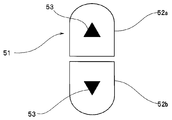
- FIG. 12B is an enlarged view of the zoom button 51.
- the zoom button 51 is a button in which two 1 ⁇ 2 oval areas constituting an enlarge button 52a and a reduce button 52b are arranged.
- the two 1 ⁇ 2 oval regions have a shape obtained by dividing an oval that is slightly smaller than the outer circumference into two in the longitudinal direction, and each 1 ⁇ 2 oval region has a small triangular portion 53 inside.
- the area formed between the enlargement button 52a and the reduction button 52b is transparent so that the image in the right image display area 33 and the frame portion 54 are displayed through.
- the enlargement button 52a and the reduction button 52b Each area is non-transparent. Accordingly, in FIG. 12A, the enlargement button 52a and the reduction button 52b hide the image and the frame portion 54 in the right image display area 33, and in the area other than the enlargement button 52a and the reduction button 52b, And the frame portion 54 are shown through.
- the enlargement button 52a or the reduction button 52b is a button for instructing enlargement or reduction of the right image display area 33.
- the user can enlarge or reduce the images displayed in the left image display area 32 and the right image display area 33 by touching the enlargement button 52a or the reduction button 52b with a finger.
- the zoom button 51 is an instruction button for instructing zooming of the endoscopic image
- the enlargement button 52a is a button for instructing enlargement of the endoscopic image
- the reduction button 52b is instructed to reduce the endoscopic image. Button.
- the zoom button 51 is displayed for a predetermined display time by a timer or the like (not shown) and is not displayed after the predetermined display time has elapsed.
- the ROM 12b stores information on zoom change amounts dg and dh.
- the zoom change amount dg is a change amount during zooming in the left image display area 32.
- the change amount dg is an amount corresponding to a change in the distance between the fingers F4 and F5 when the touch panel 14b is touched in a pinch-in or pinch-out operation. That is, the change amount dg is defined as a change amount function of the distance between the fingers F4 and F5 on the touch panel 14b.
- the zoom change amount dh is a change amount during zooming by the operation of the zoom button 51.
- the change amount dh is an amount corresponding to the number of touches when the finger touches the enlargement button 52a or the reduction button 52b or an amount corresponding to each touch. That is, the change amount dh is defined as a function of the number of times the finger has been touched on the enlargement button 52a or the reduction button 52b. Note that the amount of change dh may be defined as a function of the time of touching the finger enlargement button 52a or the reduction button 52b.
- the display range is enlarged 10 times, while the right image display area In 33, when the user touches the enlarge button 52a once, the change amounts dg and dh are defined so that the display range is enlarged by 1.1 times.
- the user touches the zoom button 51 in the right image display area 33 by zooming in on the display area by zooming in on the left image display area 32 by performing a pinch-in or pinch-out operation to zoom in the display range. Fine zooming is possible.
- the left image display area 32 is a coarse zoom area and the right image display area 33 is a fine zoom area.
- the right image display area 33 is a fine zoom area
- the right image display area 33 may be a coarse zoom area. In that case, when the user touches the right image display area 33, the right image display area 33 is selected as a coarse zoom area, and the display range is finely displayed in areas other than the right image display area 33 (such as the left image display area 32).
- a zoom button 51 for zooming is arranged.
- coarse zoom is performed by a pinch-in or pinch-out operation in the left image display area 32
- fine zoom is performed by the zoom button 51 in the right image display area 33.
- Fine zoom may be performed by a pinch-in or pinch-out operation in the left image display area 32
- coarse zoom may be performed by a zoom button 51 in the right image display area 33.
- the display range is enlarged by 1.1 times
- the change amounts dg and dh are defined so that when the enlargement button 52a is touched once, the display range is enlarged 10 times. According to this configuration, the user can quickly zoom the display range by the enlargement button 52a, and can accurately zoom the display range by a pinch-in or pinch-out operation.
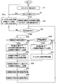
- FIG. 13 is a flowchart illustrating an example of the flow of zoom display processing in the stereo measurement mode.
- FIG. 13 the same processes as those in FIG. 13
- the control unit 12 stores information on the change amount dg that is the left eye image zoom change amount and the change amount dh that is the right eye image zoom change amount in the ROM 12B. (S51).
- the control unit 12 determines whether or not a predetermined operation has been performed on the touch panel 14b (S52). If there is no predetermined operation on the touch panel 14b, the process proceeds to S52a.
- the predetermined operation is the above-described pinch-in or pinch-out operation.
- the control unit 12 determines whether or not the zoom button 51 is already displayed, and after the zoom button 51 is already displayed and the display of the zoom button 51 is started. If the predetermined time has elapsed, the zoom button 51 is hidden (S52a).
- the process of S52a differs between the case where the zoom button 51 is not displayed and the case where the zoom button 51 is already displayed by the process of S55 described later.
- the control unit 12 determines whether or not the zoom button 51 is already displayed, and when the zoom button 51 is already displayed and the predetermined display time of the zoom button 51 has elapsed.
- the zoom button 51 is hidden (S52a). After S52a, the process returns to S1.
- the control unit 12 determines whether the operation is a pinch-in or pinch-out operation in the left image display area 32 (S53a).
- the control unit 12 uses the two fingers F4 in the left image display area 32 based on the change amount dg.
- the zoom processing of the left image display area 32 is performed from the amount of change in the distance between F5 (S54).
- the pinch-in operation the left image display area 32 is reduced, and when the pinch-out operation is performed, the left image display area 32 is enlarged.
- the control unit 12 performs a process related to the display of the zoom button 51.
- This process is performed when the zoom button 51 is not displayed by the first process or the like and when the zoom button 51 is already displayed in the second and subsequent processes. It differs depending on whether it is displayed.
- the zoom button 51 is not displayed due to the first processing or the like, the zoom button is superimposed and displayed across the frame portion 54 of the right image display area 33 at the lower right of the right image display area 33. If the zoom button 51 has already been displayed in the second and subsequent processing, it is updated so as to extend the display time (S55).
- control unit 12 zooms the right image display area 33 by the zoom amount of the left image display area 32 (S56).
- the right image display area 33 is also zoomed by the same amount as the left image display area 32.
- the control unit 12 zooms the right image display area 33 and then recalculates the display range of the right image display area 33 corresponding to the display range of the left image display area 32 by matching processing (S57).
- control unit 12 redisplays the display range of the right image display area 33 corrected by recalculation (S58).
- the recalculation of the display range of the right image display area 33 is performed after zooming the right image display area 33 (S56), but the display range of the right image display area 33 is recalculated in S56.
- the right image display area 33 may be zoomed while correcting by calculation.
- the control unit 12 When the operation in S53a is not a pinch-in or pinch-out operation in the left image display area 32 (S53a: NO), the control unit 12 further performs an enlargement button 52a or a reduction in the zoom button 51 of the right image display area 33 in S53a. It is determined whether the touch operation is on the button 52b (S53b). When the operation in S53b is not a touch operation of the enlarge button 52a or the reduce button 52b in the right image display area 33 (S53b: NO), the process returns to S52.
- the control unit 12 determines which of the enlargement button 52a and the reduction button 52b is touched, and enlarges the display range of the left image display area 32 when the enlargement button 52a is touched based on the change amount dh.
- the reduction button 52b is touched, the left image display area 32 is reduced (S59).
- the control unit 12 updates the display time of the zoom button 51 to be extended (S60).
- the processing in FIG. 13 ends when the user instructs the end of the stereo measurement processing mode on the menu screen.
- the operation from S54 to S60 receives an operation instruction for a zoom operation such as a pinch-in or pinch-out operation while the left image display region 32 is selected
- the left image display region 32 and the right image display are displayed.
- the display range of the area 33 is changed by the change amount dg and an operation instruction such as a touch operation of the zoom button 51 is received while the right image display area 33 is selected
- a display control unit is configured to perform display control so that the display range 33 is changed by a change amount dh different from the change amount dg.
- the change amount dg is set to be larger than the change amount dh
- the user performs a pinch-in or pinch-out operation in the left image display area 32 by repeating the processing of FIG.
- a coarse zoom that greatly changes the display range of the left image display region 32 and the display range of the right image display region 33, and the display range of the left image display region 32 and the right by touching the zoom button 51 of the right image display region 33
- the fine zoom for changing the display range of the image display area 33 to be small can be repeated one or more times.
- the user can quickly and accurately zoom the display range of the left image display area 32 and the display range of the right image display area 33 to a desired size.
- the cursor display process of the first embodiment or the third embodiment described above, the zoom process of the second embodiment, or the zoom process of the fourth embodiment You may be able to do both.
- the change amounts da, db, de, and df may be different according to the zoom amount of the endoscopic image.
- the cursor display process or the zoom process is executed in the stereo measurement mode, but the same endoscopic image is displayed in the two image display areas in other modes other than the stereo measurement mode.
- the cursor display process or zoom process described above may be executed even during the time. For example, it is convenient when a certain point is specified quickly and accurately on the same endoscopic image, when a certain point is marked quickly and accurately, or when zooming is performed quickly and accurately.
- the endoscope apparatus 1 displays two image display areas on the display unit 14, but may display three or more image display areas. In that case, the change amount of the cursor and the change amount at the time of zooming differ between the plurality of image display areas.
- the display magnification of the third image display area is set to the left image display area 32 and the right image display area.
- the movement amount or zoom amount of the point in the third image display area is the movement amount or zoom amount of the point in the left image display area 32 and the right image display area 33. Different.
- the cursor movement operation and the zoom operation described above use a touch panel.
- the measurement point specifying operation is performed using the joystick of the operation unit 15, and the zoom operation is performed using the operation unit 15. You may make it perform using the zoom operation button provided in.
- the direction of the joystick can be specified depending on the tilting direction.
- the cursor 35 a on the left image display area 32 when the cursor 35 a on the left image display area 32 is dragged, the finger F moves beyond the left image display area 32 or the cursor on the right image display area 33.
- the finger F moves beyond the right image display area 33 when the drag operation is performed on 35b, when the drag operation is performed beyond the image display area first touched by the finger F, It has been described that the cursor 35a and 35b may be moved by continuously using the change value for the image display area touched by the finger F first.
- the cursor 35a moves or zooms large in the left image display area 32, and the cursor 35b moves small or zooms small in the right image display area 33, but the left image display area In 32, the cursor 35a may move small or the zoom amount may be small, and in the right image display area 33, the cursor 35b may move large or the zoom amount may be large.
- two inspectors who face each other may view an image displayed on one display unit of the endoscope apparatus.
- some endoscope apparatuses can change (that is, invert) the orientation of the screen of the display unit by 180 degrees.
- the screen direction of the display unit is changed by 180 degrees (that is, inverted), the vertical direction of the screen of the display unit is reversed.
- the left and right image display areas may be interchanged.
- the data of the respective change amounts da, db, dc, dd, df, dg, and dh are stored in the ROM 12b, but are stored in a memory card or the like, and the memory card I / F 17 You may read out via. If the memory card is a rewritable memory, for example, a flash memory, the value of each change amount da, db, dc, dd, df, dg, dh may be changed by the user.
- the move button is displayed by touching the right image display area or the left image display area and is not displayed after a predetermined time has elapsed, but the move button is displayed or not displayed. It is good also as a structure provided with the switch button to be made. According to this configuration, the user can freely switch between display and non-display of the movement button, improve the operability of the movement button, and consequently specify the position of a measurement point or the like in the endoscopic image with a small number of operations. Can be done quickly. Even when the movement button is switched to be displayed, the movement button is automatically hidden during the touch operation so that the movement button does not hinder the movement during the movement.
- the zoom button is displayed by touching the right image display area or the left image display area and is not displayed after a predetermined time has elapsed, but the zoom button is displayed or not displayed. It is good also as a structure provided with the switch button to be made. According to this configuration, the user can freely switch between displaying and hiding the zoom button, improving the operability of the zoom button, and, in turn, quickly changing the display range of the endoscope display with a small number of operations. It can be carried out. Even when the zoom button is switched to display, the zoom button is automatically hidden during the touch operation so that the zoom button is not hindered.
- each “unit” in this specification is a conceptual one corresponding to each function of the embodiment, and does not necessarily correspond to a specific hardware or software routine on a one-to-one basis.
- each step of each procedure in the present embodiment may be executed in a different order for each execution by changing the execution order and performing a plurality of steps at the same time, as long as it does not contradict its nature.
- all or a part of each step of each procedure in the present embodiment may be realized by hardware.
- an endoscope image display device an endoscope image display method, and an endoscope image display program can be provided.
Landscapes
- Engineering & Computer Science (AREA)
- Signal Processing (AREA)
- Health & Medical Sciences (AREA)
- Life Sciences & Earth Sciences (AREA)
- Multimedia (AREA)
- Surgery (AREA)
- Physics & Mathematics (AREA)
- Heart & Thoracic Surgery (AREA)
- Molecular Biology (AREA)
- Biophysics (AREA)
- Nuclear Medicine, Radiotherapy & Molecular Imaging (AREA)
- Optics & Photonics (AREA)
- Pathology (AREA)
- Radiology & Medical Imaging (AREA)
- Veterinary Medicine (AREA)
- Biomedical Technology (AREA)
- Public Health (AREA)
- General Health & Medical Sciences (AREA)
- Animal Behavior & Ethology (AREA)
- Medical Informatics (AREA)
- General Physics & Mathematics (AREA)
- Theoretical Computer Science (AREA)
- Computer Vision & Pattern Recognition (AREA)
- Human Computer Interaction (AREA)
- Business, Economics & Management (AREA)
- Marketing (AREA)
- Instruments For Viewing The Inside Of Hollow Bodies (AREA)
- Endoscopes (AREA)
Abstract
L'invention concerne un dispositif d'endoscope (1) qui a une unité de commande (12) et une partie d'affichage (14) dotée d'un panneau tactile ayant une région d'affichage d'image gauche (32) et une région d'affichage d'image droite (33). Une fois que l'unité de commande (12) a reçu une instruction de mise en œuvre de glissement lorsque la région d'affichage d'image gauche (32) a été sélectionnée, l'unité de commande (12) réalise une commande d'affichage de façon à amener la position de curseurs (35a et 35b), affichés dans la région d'affichage d'image gauche (32) et la région d'affichage d'image droite (33), à changer par une variation da. Une fois que l'unité de commande (12) a reçu une instruction de mise en œuvre de glissement lorsque la région d'affichage d'image droite (33) a été sélectionnée, l'unité de commande (12) réalise une commande d'affichage de façon à amener la position des curseurs (35a et 35b), affichés dans la région d'affichage d'image gauche (32) et la région d'affichage d'image droite (33), à changer par une variation db qui est différente de la variation da.
Priority Applications (1)
| Application Number | Priority Date | Filing Date | Title |
|---|---|---|---|
| US15/700,354 US10419705B2 (en) | 2015-03-13 | 2017-09-11 | Endoscope image display apparatus, endoscope image display method and endoscope image display program |
Applications Claiming Priority (2)
| Application Number | Priority Date | Filing Date | Title |
|---|---|---|---|
| JP2015051181A JP6485831B2 (ja) | 2014-04-17 | 2015-03-13 | 内視鏡画像表示装置、内視鏡画像表示方法及び内視鏡画像表示プログラム |
| JP2015-051181 | 2015-03-13 |
Related Child Applications (1)
| Application Number | Title | Priority Date | Filing Date |
|---|---|---|---|
| US15/700,354 Continuation US10419705B2 (en) | 2015-03-13 | 2017-09-11 | Endoscope image display apparatus, endoscope image display method and endoscope image display program |
Publications (1)
| Publication Number | Publication Date |
|---|---|
| WO2016147697A1 true WO2016147697A1 (fr) | 2016-09-22 |
Family
ID=56932202
Family Applications (1)
| Application Number | Title | Priority Date | Filing Date |
|---|---|---|---|
| PCT/JP2016/051845 Ceased WO2016147697A1 (fr) | 2015-03-13 | 2016-01-22 | Dispositif d'affichage d'image d'endoscope, procédé d'affichage d'image d'endoscope, et programme d'affichage d'image d'endoscope |
Country Status (3)
| Country | Link |
|---|---|
| US (1) | US10419705B2 (fr) |
| JP (1) | JP6485831B2 (fr) |
| WO (1) | WO2016147697A1 (fr) |
Cited By (1)
| Publication number | Priority date | Publication date | Assignee | Title |
|---|---|---|---|---|
| WO2020003862A1 (fr) * | 2018-06-27 | 2020-01-02 | 富士フイルム株式会社 | Dispositif d'imagerie, procédé d'imagerie, et programme |
Families Citing this family (3)
| Publication number | Priority date | Publication date | Assignee | Title |
|---|---|---|---|---|
| JP2020022563A (ja) | 2018-08-06 | 2020-02-13 | ソニー・オリンパスメディカルソリューションズ株式会社 | 医療用観察装置 |
| JP7187286B2 (ja) * | 2018-11-29 | 2022-12-12 | キヤノン株式会社 | 画像処理装置、画像処理方法及びプログラム |
| CN111314686B (zh) * | 2020-03-20 | 2021-06-25 | 深圳市博盛医疗科技有限公司 | 一种自动优化3d立体感的方法、系统及介质 |
Citations (5)
| Publication number | Priority date | Publication date | Assignee | Title |
|---|---|---|---|---|
| JP2006136706A (ja) * | 2004-10-12 | 2006-06-01 | Olympus Corp | 計測用内視鏡装置及び内視鏡用プログラム |
| JP2011027997A (ja) * | 2009-07-24 | 2011-02-10 | Olympus Corp | 内視鏡装置、計測方法、およびプログラム |
| US20120154564A1 (en) * | 2008-03-28 | 2012-06-21 | Intuitive Surgical Operations, Inc. | Apparatus for automated panning and digital zooming in robotic surgical systems |
| JP2013137466A (ja) * | 2011-12-28 | 2013-07-11 | Olympus Corp | 内視鏡画像処理装置及び内視鏡画像処理用プログラム |
| JP2013218517A (ja) * | 2012-04-09 | 2013-10-24 | Panasonic Corp | 入出力装置 |
Family Cites Families (10)
| Publication number | Priority date | Publication date | Assignee | Title |
|---|---|---|---|---|
| JPH02119836A (ja) * | 1988-10-28 | 1990-05-07 | Olympus Optical Co Ltd | 立体内視鏡装置 |
| JP2002315753A (ja) * | 2001-04-20 | 2002-10-29 | Olympus Optical Co Ltd | 画像診断装置 |
| JP2006226820A (ja) | 2005-02-17 | 2006-08-31 | Hcx:Kk | ナビゲーション装置 |
| US7443488B2 (en) | 2005-05-24 | 2008-10-28 | Olympus Corporation | Endoscope apparatus, method of operating the endoscope apparatus, and program to be executed to implement the method |
| JP5199594B2 (ja) * | 2006-03-24 | 2013-05-15 | オリンパス株式会社 | 画像計測装置および方法 |
| EP2207056B1 (fr) * | 2007-10-30 | 2013-01-09 | Olympus Corporation | Dispositif endoscopique |
| JP5391917B2 (ja) * | 2009-08-10 | 2014-01-15 | 株式会社ニコン | ヘッドマウントディスプレイ |
| JP5437087B2 (ja) * | 2010-01-15 | 2014-03-12 | オリンパス株式会社 | 内視鏡装置およびプログラム |
| US20140066703A1 (en) * | 2010-06-18 | 2014-03-06 | Vantage Surgical Systems Inc. | Stereoscopic system for minimally invasive surgery visualization |
| US10157495B2 (en) * | 2011-03-04 | 2018-12-18 | General Electric Company | Method and device for displaying a two-dimensional image of a viewed object simultaneously with an image depicting the three-dimensional geometry of the viewed object |
-
2015
- 2015-03-13 JP JP2015051181A patent/JP6485831B2/ja active Active
-
2016
- 2016-01-22 WO PCT/JP2016/051845 patent/WO2016147697A1/fr not_active Ceased
-
2017
- 2017-09-11 US US15/700,354 patent/US10419705B2/en active Active
Patent Citations (5)
| Publication number | Priority date | Publication date | Assignee | Title |
|---|---|---|---|---|
| JP2006136706A (ja) * | 2004-10-12 | 2006-06-01 | Olympus Corp | 計測用内視鏡装置及び内視鏡用プログラム |
| US20120154564A1 (en) * | 2008-03-28 | 2012-06-21 | Intuitive Surgical Operations, Inc. | Apparatus for automated panning and digital zooming in robotic surgical systems |
| JP2011027997A (ja) * | 2009-07-24 | 2011-02-10 | Olympus Corp | 内視鏡装置、計測方法、およびプログラム |
| JP2013137466A (ja) * | 2011-12-28 | 2013-07-11 | Olympus Corp | 内視鏡画像処理装置及び内視鏡画像処理用プログラム |
| JP2013218517A (ja) * | 2012-04-09 | 2013-10-24 | Panasonic Corp | 入出力装置 |
Cited By (7)
| Publication number | Priority date | Publication date | Assignee | Title |
|---|---|---|---|---|
| WO2020003862A1 (fr) * | 2018-06-27 | 2020-01-02 | 富士フイルム株式会社 | Dispositif d'imagerie, procédé d'imagerie, et programme |
| JPWO2020003862A1 (ja) * | 2018-06-27 | 2021-04-22 | 富士フイルム株式会社 | 撮像装置、撮像方法、及びプログラム |
| JP2021132383A (ja) * | 2018-06-27 | 2021-09-09 | 富士フイルム株式会社 | 撮像装置、撮像方法、プログラム、及び記録媒体 |
| US11216118B2 (en) | 2018-06-27 | 2022-01-04 | Fujifilm Corporation | Imaging apparatus, imaging method, and program |
| JP7152557B2 (ja) | 2018-06-27 | 2022-10-12 | 富士フイルム株式会社 | 撮像装置、撮像方法、プログラム、及び記録媒体 |
| US11635856B2 (en) | 2018-06-27 | 2023-04-25 | Fujifilm Corporation | Imaging apparatus, imaging method, and program |
| US11954290B2 (en) | 2018-06-27 | 2024-04-09 | Fujifilm Corporation | Imaging apparatus, imaging method, and program |
Also Published As
| Publication number | Publication date |
|---|---|
| US10419705B2 (en) | 2019-09-17 |
| JP6485831B2 (ja) | 2019-03-20 |
| JP2015211824A (ja) | 2015-11-26 |
| US20180013973A1 (en) | 2018-01-11 |
Similar Documents
| Publication | Publication Date | Title |
|---|---|---|
| US10666854B2 (en) | Bending operation control for endoscope | |
| JP4326568B2 (ja) | 情報処理装置および情報処理プログラム | |
| JP5363259B2 (ja) | 画像表示装置、画像表示方法およびプログラム | |
| US10969949B2 (en) | Information display device, information display method and information display program | |
| US9214139B2 (en) | Image display apparatus and image display method | |
| JP6485831B2 (ja) | 内視鏡画像表示装置、内視鏡画像表示方法及び内視鏡画像表示プログラム | |
| JPWO2007135835A1 (ja) | 画像操作装置、画像操作方法、及び画像操作プログラム | |
| KR102103957B1 (ko) | 플렉서블 디스플레이 장치의 표시 영역 제어 방법, 장치 및 이를 기록한 기록매체 | |
| JP2014063448A (ja) | 情報処理装置、情報処理方法、および情報処理プログラム | |
| JP2016220830A (ja) | 医用画像表示装置及び超音波診断装置 | |
| JP2009116906A (ja) | 情報処理装置および情報処理プログラム | |
| JP2019170853A (ja) | タッチパネル装置、湾曲制御プログラム、湾曲制御プログラムを記録した記録媒体、及び、内視鏡の湾曲制御方法 | |
| JP6373710B2 (ja) | 図形処理装置および図形処理プログラム | |
| JP6429541B2 (ja) | 内視鏡画像表示装置、内視鏡画像表示装置の作動方法、内視鏡画像表示プログラム | |
| JP5888793B2 (ja) | オブジェクト制御プログラム及びオブジェクト制御方法 | |
| US20210008709A1 (en) | Control apparatus, control method, and master-slave system | |
| WO2013099305A1 (fr) | Dispositif de traitement d'images endoscopiques, procédé de réglage d'une position sur une image endoscopique, et support d'enregistrement | |
| KR20160052305A (ko) | 초음파 진단 장치 및 이의 제어 방법 | |
| JP2013225321A (ja) | 情報処理プログラム、情報処理装置、情報処理システム、および情報処理方法 | |
| JP2011106946A (ja) | 波形表示装置および波形表示方法 | |
| JP6526851B2 (ja) | 図形処理装置および図形処理プログラム | |
| WO2017038321A1 (fr) | Dispositif d'endoscopie et procédé de commande du changement d'affichage du dispositif d'endoscopie | |
| JP2007316452A (ja) | 観察装置および観察装置の画面表示方法 | |
| JP5738372B2 (ja) | 情報処理装置、情報処理プログラム、情報処理システム、および情報処理方法 | |
| JP2014002554A (ja) | 表示装置および表示装置の制御方法 |
Legal Events
| Date | Code | Title | Description |
|---|---|---|---|
| 121 | Ep: the epo has been informed by wipo that ep was designated in this application |
Ref document number: 16764528 Country of ref document: EP Kind code of ref document: A1 |
|
| NENP | Non-entry into the national phase |
Ref country code: DE |
|
| 122 | Ep: pct application non-entry in european phase |
Ref document number: 16764528 Country of ref document: EP Kind code of ref document: A1 |