WO2016147703A1 - プレス成形(press forming)方法及びプレス成形金型(tool of press forming) - Google Patents
プレス成形(press forming)方法及びプレス成形金型(tool of press forming) Download PDFInfo
- Publication number
- WO2016147703A1 WO2016147703A1 PCT/JP2016/052300 JP2016052300W WO2016147703A1 WO 2016147703 A1 WO2016147703 A1 WO 2016147703A1 JP 2016052300 W JP2016052300 W JP 2016052300W WO 2016147703 A1 WO2016147703 A1 WO 2016147703A1
- Authority
- WO
- WIPO (PCT)
- Prior art keywords
- press
- vertical wall
- die
- molding
- blank material
- Prior art date
- Legal status (The legal status is an assumption and is not a legal conclusion. Google has not performed a legal analysis and makes no representation as to the accuracy of the status listed.)
- Ceased
Links
Images







Classifications
-
- B—PERFORMING OPERATIONS; TRANSPORTING
- B21—MECHANICAL METAL-WORKING WITHOUT ESSENTIALLY REMOVING MATERIAL; PUNCHING METAL
- B21D—WORKING OR PROCESSING OF SHEET METAL OR METAL TUBES, RODS OR PROFILES WITHOUT ESSENTIALLY REMOVING MATERIAL; PUNCHING METAL
- B21D19/00—Flanging or other edge treatment, e.g. of tubes
- B21D19/08—Flanging or other edge treatment, e.g. of tubes by single or successive action of pressing tools, e.g. vice jaws
-
- B—PERFORMING OPERATIONS; TRANSPORTING
- B21—MECHANICAL METAL-WORKING WITHOUT ESSENTIALLY REMOVING MATERIAL; PUNCHING METAL
- B21D—WORKING OR PROCESSING OF SHEET METAL OR METAL TUBES, RODS OR PROFILES WITHOUT ESSENTIALLY REMOVING MATERIAL; PUNCHING METAL
- B21D22/00—Shaping without cutting, by stamping, spinning, or deep-drawing
- B21D22/02—Stamping using rigid devices or tools
-
- B—PERFORMING OPERATIONS; TRANSPORTING
- B21—MECHANICAL METAL-WORKING WITHOUT ESSENTIALLY REMOVING MATERIAL; PUNCHING METAL
- B21D—WORKING OR PROCESSING OF SHEET METAL OR METAL TUBES, RODS OR PROFILES WITHOUT ESSENTIALLY REMOVING MATERIAL; PUNCHING METAL
- B21D22/00—Shaping without cutting, by stamping, spinning, or deep-drawing
- B21D22/20—Deep-drawing
-
- B—PERFORMING OPERATIONS; TRANSPORTING
- B21—MECHANICAL METAL-WORKING WITHOUT ESSENTIALLY REMOVING MATERIAL; PUNCHING METAL
- B21D—WORKING OR PROCESSING OF SHEET METAL OR METAL TUBES, RODS OR PROFILES WITHOUT ESSENTIALLY REMOVING MATERIAL; PUNCHING METAL
- B21D37/00—Tools as parts of machines covered by this subclass
- B21D37/10—Die sets; Pillar guides
-
- B—PERFORMING OPERATIONS; TRANSPORTING
- B21—MECHANICAL METAL-WORKING WITHOUT ESSENTIALLY REMOVING MATERIAL; PUNCHING METAL
- B21D—WORKING OR PROCESSING OF SHEET METAL OR METAL TUBES, RODS OR PROFILES WITHOUT ESSENTIALLY REMOVING MATERIAL; PUNCHING METAL
- B21D22/00—Shaping without cutting, by stamping, spinning, or deep-drawing
- B21D22/20—Deep-drawing
- B21D22/21—Deep-drawing without fixing the border of the blank
-
- B—PERFORMING OPERATIONS; TRANSPORTING
- B21—MECHANICAL METAL-WORKING WITHOUT ESSENTIALLY REMOVING MATERIAL; PUNCHING METAL
- B21D—WORKING OR PROCESSING OF SHEET METAL OR METAL TUBES, RODS OR PROFILES WITHOUT ESSENTIALLY REMOVING MATERIAL; PUNCHING METAL
- B21D22/00—Shaping without cutting, by stamping, spinning, or deep-drawing
- B21D22/20—Deep-drawing
- B21D22/30—Deep-drawing to finish articles formed by deep-drawing
Definitions
- the present invention relates to a metal sheet press molding method and a press molding die, and more particularly to a press molding method and a press molding die for suppressing wrinkles in foam forming.
- Patent Document 1 discloses a method for manufacturing an L-shaped product by press working. According to this method, wrinkles are generated on the top wall of the L-shaped product and cracks are formed in stretch flange forming by pressing using a pad for suppressing wrinkles. (Fracture) can be avoided.
- Patent Document 2 discloses a method for manufacturing a part having an arc-shaped portion at a corner without causing wrinkles in a side wall portion.
- the method comprises a step of producing an intermediate molded product that does not mold the arc-shaped portion, and a step of drawing the arc-shaped portion from the intermediate molded product produced by the step to complete the corner portion. It is said that the generation of wrinkles can be avoided by making one or more incisions starting from the edge side of the flange portion in the unreachable portion.
- Patent Document 3 discloses that a metal plate material (steel blank sheet) is bent into a hat-shaped cross section and immediately after the bending process is completed, a compressive force is applied to the vertical wall portion of the metal plate material.
- a press mold (tool of press forming) is disclosed.
- a pad load is applied in advance to the area where wrinkles occur, so that the material surplus
- this method can be applied to the top part of the part that can be sandwiched between the punch and the pad at the beginning of press molding, but has a large inclination with respect to the driving direction of the press machine. Not applicable to side wall portion of part.
- the blank material is clamped by the punch and the pad, and the wrinkles near the curved portion (curved portion) of the upper wall are maintained by maintaining the height of the pad as it is. Although it suppresses, it can suppress the generation of wrinkles only on the upper wall of the product and cannot be applied to a foam molded part in which wrinkles are generated on the vertical wall.
- Patent Document 2 Since the method described in Patent Document 2 requires at least two steps for manufacturing a part, it is difficult to produce the product, and it is necessary to make a notch in the blank material. There was a problem that would become.
- the upper bending blade of the die is moved in the horizontal direction by the suspended slider attached to the upper die so as to be slidable.
- the upper half of the wall is sandwiched and the lower half is pressed to compress the vertical wall.
- the curvature of the vertical wall portion changes during the bending process, so
- the shape of the bending blade must be changed in accordance with the curvature of curvature in the bending process, the shape of the upper bending blade cannot be changed in the bending process in the press die of Patent Document 3. Therefore, the press die described in Patent Document 3 cannot manufacture a press-formed product having a vertical wall portion that is curved in a convex shape in a plan view toward the outside.
- the present invention has been made in view of the above-described circumstances, and in the foam molding of a press-molded product having a vertical wall portion that is curved in a plan view toward the outside in the longitudinal direction of the press-molded product, a blank is provided. It is an object of the present invention to provide a press molding method and a press mold that can form a vertical wall portion in one step without making a notch in the material, and suppress the occurrence of wrinkles in the vertical wall portion. To do.
- the press molding method according to the present invention is a press molding method of a press molded product having no flange portion, and includes at least a top portion and the top plate portion.
- a press having a vertical wall portion (side wall portion) continuous through a connection portion on the top plate portion, and the whole or a part of the vertical wall portion is curved in a convex shape in plan view toward the outside of the press-formed product.
- the vertical wall portion is formed in a state in which the above-described restriction is not performed.
- the press molding method according to the present invention is characterized in that, in the above-mentioned invention, the tip of the blank material is in a range of a distance from the tip of the blank material to four times the plate thickness. .
- a press molding die according to the present invention is used for the press molding method according to any one of the above inventions, and has a punch and a die, and a cross section of a vertical wall molding portion of the die.
- the shape is characterized in that the tip of the blank material is always in contact with the vertical wall forming portion during the vertical wall forming.
- the vertical wall molding section has a cross-sectional shape having a distance range from the tip of the blank material to four times the plate thickness during the vertical wall molding. The shape is always in contact with the vertical wall forming portion.
- the press molding die according to the present invention is a press molded product having no flange portion, and has at least a top plate portion and a vertical wall portion continuous to the top plate portion via a connection portion, Forming the press-formed product in which the whole or a part of the vertical wall portion is curved in a convex shape in a plan view toward the outside of the press-formed product, and a top plate forming part on which a blank material is placed;
- a punch shoulder portion that is continuous with the top plate forming portion and follows the curvature of the press-formed product, a punch having a vertical wall forming portion continuous with the punch shoulder portion, and a relative movement with respect to the punch
- the center point of curvature is the origin, and the horizontal direction is A curve expressed
- the press-molding method and press-molding die according to the present invention suppress the occurrence of wrinkles without making a notch in a blank material, with a vertical wall curved in a plan view toward the outside of a press-molded product. Thus, it is possible to easily mold in one step.
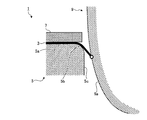
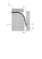
- FIG. 1 is a cross-sectional view showing a configuration example of a press-molding die used in the description of the press-molding method according to Embodiment 1 of the present invention and a press-molding die according to Embodiment 2.
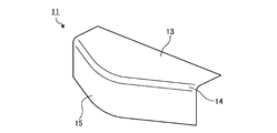
- FIG. 2 is a perspective view showing an example of a press-formed product according to the present invention.
- FIG. 3 is a perspective view showing an example of a press-formed product formed using a conventional press-molding die.
- FIG. 4 is a diagram for explaining the deformation behavior at the tip of the blank material during press molding.
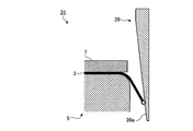
- FIG. 5 is a cross-sectional view showing an example of a press molding die in which the vertical wall molding portion of the die according to the present invention is a flat inclined surface.
- FIG. 1 is a cross-sectional view showing a configuration example of a press-molding die used in the description of the press-molding method according to Embodiment 1 of the present invention and a press-molding die according to Em
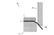
- FIG. 6 is a diagram illustrating a conventional press mold.
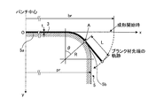
- FIG. 7 is a diagram for explaining a cross-sectional shape of a press-molding die used in the press-molding method according to Embodiment 2 of the present invention.
- FIG. 8 is a diagram illustrating the locus of the tip of the blank material during press molding in Embodiment 2 of the present invention.
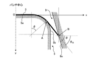
- FIG. 9 is a diagram for explaining the deformation of the blank material and the inclination angle of the vertical wall forming portion of the die with respect to the horizontal direction in the second embodiment of the present invention.
- FIG. 10 is a diagram showing an example of the calculation result of the locus of the tip of the blank material and the optimum curve.
- FIG. 11 is a perspective view illustrating a vertical wall forming portion of a die of a press mold according to the second embodiment of the present invention.
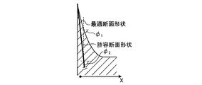
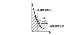
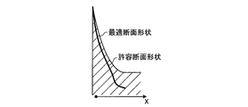
- FIG. 12-1 is a diagram for explaining an example 1 of an allowable cross-sectional shape of the vertical wall forming portion according to the second embodiment of the present invention.
- FIG. 12-2 is a diagram for explaining an example 2 of an allowable cross-sectional shape of the vertical wall forming portion according to the second embodiment of the present invention.
- FIG. 12-3 is a diagram for explaining an example 3 of the allowable cross-sectional shape of the vertical wall forming portion according to the second embodiment of the present invention.
- FIG. 13-1 is a diagram for explaining another example of the allowable cross-sectional shape of the vertical wall forming portion according to the second embodiment of the present invention.
- FIG. 12-1 is a diagram for explaining an example 1 of an allowable cross-sectional shape of the vertical wall forming portion according to the second embodiment of the present invention.
- FIG. 12-2 is a diagram for explaining an example
- FIG. 13-2 is a diagram for explaining an example of an unacceptable cross-sectional shape of the vertical wall forming portion according to the second embodiment of the present invention.
- FIG. 14-1 is a diagram for explaining an example of the size of the blank material in the second embodiment of the present invention.
- FIG. 14-2 is a diagram for explaining another example of the size of the blank material in the second embodiment of the present invention.
- FIG. 15 is a diagram illustrating a press-formed product targeted in Example 1 and Example 3.
- FIG. FIG. 16 is a diagram illustrating the shape of a blank material for forming a target press-formed product in the second embodiment.
- the press molding method according to Embodiment 1 of the present invention is to form a press molded product 11 having no flange portion as shown in FIG. 2 by using the press molding die 1 shown in FIG. .
- the press-formed product 11 includes at least a top plate portion 13 and a vertical wall portion 15 that continues to the top plate portion 13 via a connection portion 14. The whole or a part is curved outwardly in a convex shape in plan view.
- a press-molded product 11 as shown in FIG. 2 is formed with a punch 5, a pad 7 and a die 9 of a press-molding die 1 as shown in FIG.
- the front end of the blank material 3 is always brought into contact with the die 9 and the vertical molding of the press-molded product 11 is performed in the vertical wall molding portion 9a without any restriction other than the contact by the die 9.
- the wall 15 is formed.
- the height of the vertical wall portion 15 of the press-formed product 11 is When the height exceeds a certain height, shrink deformation concentrates on the lower end of the vertical wall portion 15 and wrinkles 19 are generated (see FIG. 3). This wrinkle is considered to be generated by the following mechanism.
- the front end portion of the blank material 3 (see FIG. 1) corresponding to the lower end of the vertical wall portion 15 is not buckled, and the line length
- the deformation of the tip portion requires shrink deformation energy in the in-plane direction and deformation energy for increasing the plate thickness.
- the bending deformation energy in the off-plane direction should be smaller than the sum of the shrinkage deformation energy in the in-plane direction and the deformation energy of increasing the plate thickness when the tip does not buckle.
- the tip portion is buckled.
- wrinkles are generated outward at the lower end of the vertical wall portion 15.
- the tip of the blank 3 is pressed by the die 9 so as not to spread outward as shown in FIG. Can be suppressed.
- the tip of the blank 3 is brought into contact with the die 9 so as to be pressed from the outside, and the tip of the blank 3 is molded in a state where no constraint other than this contact is imposed. It is possible to prevent the tip from being deformed and to prevent the tip portion from being wrinkled. And since the state where wrinkles tend to occur outward continues from the middle of molding to the end of molding, it is necessary to always bring the tip of the blank material 3 into contact with the die 9 and press the tip from the outside.
- this Embodiment 1 is a press molding method which forms as it presses the upper surface of the blank material 3 with the pad 7 as shown in FIG. 1, it forms without pressing the blank material 3 with the pad 7. Even if it exists, if the front-end
- the vertical wall portion 15 can be formed without generating wrinkles in the eleven vertical wall portions 15.
- the tip of the blank 3 that is brought into contact with the vertical wall molding 9a of the die 9 during molding may be within a distance range from the tip of the blank 3 to four times the plate thickness as in Example 1 described later.
- the vertical wall portion 15 can be formed without generating wrinkles in the vertical wall portion 15.
- the press-molding die 1 according to the second embodiment of the present invention includes at least a top plate portion 13 and a top plate portion 13 via a connecting portion 14 as shown in FIG.
- a press-formed product 11 having a continuous vertical wall portion 15 and having the whole or a part of the vertical wall portion 15 curved outwardly in a plan view is formed.
- the press-molding die 1 includes a punch 5 that supports the lower surface of a flat blank 3, and a blank 3 that is supported by a forming top portion 5 a of the punch 5.
- a pad 7 that presses the upper surface, and a die 9 that is bent by the vertical wall forming portion 9a coming into contact with the blank 3 sandwiched between the punch 5 and the pad 7 are provided.
- the punch 5 includes a top plate forming portion 5a, a punch portion 5b that extends obliquely downward from the end portion of the top plate forming portion 5a, and a vertical portion that extends downward from the lower end side of the punch shoulder portion 5b. And a forming wall portion 5c.
- the top plate forming portion 5a supports the lower surface of the blank 3 that is a flat surface.
- the cross-sectional shape of the punch shoulder 5b is an arc with a radius of curvature R.
- the pad 7 is disposed so as to face the top plate forming portion 5a of the punch 5, and can be moved up and down.
- the blank material 3 can be sandwiched between the punch 5 and the pad 7 by placing the blank material 3 on the top plate forming portion 5a of the punch 5 and moving and pressing the pad 7 toward the punch 5 side.
- the die 9 has a vertical wall forming portion 9 a that abuts against the blank material 3 to bend the blank material 3 and forms the vertical wall portion 15 of the press-formed product 11.
- the vertical wall forming portion 9a has a curved shape as shown in FIG.
- the tip of the blank 3 can always be brought into contact with the vertical wall molding part 9a during molding.
- the tip of the blank 3 is always used as the vertical wall forming portion 39a during forming. Can be contacted.
- the cross-sectional shape of the shoulder portion 29b is determined by the cross-sectional shape of the connecting portion between the vertical wall portion and the flange portion in this press-formed product.
- the cross-sectional shape of the die shoulder 29b can be set regardless of the product shape of the press-molded product 11 after molding.
- the cross-sectional shape of the vertical wall forming portion 9a for always contacting the tip of the blank 3 with the die 9 during the forming was examined.
- the vertical wall forming portion 9a of the die 9 is an inclined surface having a constant inclination angle as shown in FIG. 7 was examined.
- the vertical wall forming portion 9a of the die 9 has an inclined surface with a constant inclination angle as shown in FIG. 7, the vertical wall of the die 9 is formed so that the tip of the blank material 3 is always in contact with the die 9.
- the inclination angle ⁇ 2 with respect to the horizontal direction of the inclined surface forming the forming portion 9a is equal to or greater than the inclination angle ⁇ 1 with respect to the horizontal direction of the vertical wall portion 15 of the press-formed product 11 near the front end of the blank 3 at the bottom dead center. It is necessary to be.
- the inclination angle ⁇ 2 of the inclined surface having a constant inclination angle as described above is set to a constant value equal to or greater than the inclination angle ⁇ 1 in the vicinity of the tip of the blank member 3 (see FIG. 7), the blank member 3 is formed to be dead.
- the vertical wall portion 15 is nearly vertical, it is necessary to make the inclination angle ⁇ 2 of the inclined surface close to 90 degrees, and the molding stroke of the die 9 must be very long. .
- the inventor has a curve in which the inclination angle of the vertical wall molding portion 9a with respect to the horizontal direction changes in accordance with the cross-sectional shape of the vertical wall molding portion 9a in accordance with the position where the tip of the blank 3 contacts the die 9 during molding. It has been found that the tip of the blank 3 can always be brought into contact with the vertical wall forming portion 9a without lengthening the forming stroke.
- the specific cross-sectional shape in which the inclination angle of the vertical wall forming portion 9a with respect to the horizontal direction changes was determined as follows. As shown in FIG. 8, the punch radius in the plane parallel to the horizontal direction of the top plate forming portion 5a of the punch 5 is pr [mm], the curvature radius of the punch shoulder portion 5b is R [mm], and the blank 3 The blank material radius in a plane parallel to the horizontal direction of the top plate forming portion 5a is br [mm], and the plate thickness of the blank material 3 is t [mm]. In this case, the distance L from the point (point A in FIG.
- the locus of the tip position of the blank 3 during molding has the origin O as the center of the curvature radius in the horizontal direction on the top plate forming portion 5a, and the horizontal of the top plate forming portion 5a. It can be represented by a point (x, y) represented by the following equation on the xy coordinates with the direction being the x-axis and the vertical direction of the top plate forming portion 5a being the y-axis.
- the angle ⁇ B with respect to the horizontal direction in the direction parallel to the portion in contact with the vertical wall forming portion 9 a of the blank 3 at the tip of the blank 3 is the winding angle ⁇ of the punch shoulder 5 b of the blank 3. Is equal to From this, in order for the vertical wall forming portion 9a of the die 9 to have a cross-sectional shape that always contacts the tip of the blank material 3, the vertical wall at the point where the tip of the blank material 3 contacts (point B in FIG. 9).
- a point that is the center of the curvature radius of the curvature in the horizontal direction on the top plate forming portion 5a of the punch 5 is defined as an origin O
- the horizontal direction of the top plate forming portion 5a is defined as an X axis
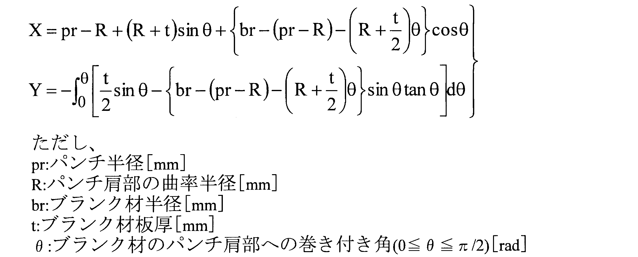
- the top plate forming portion 5a When the surface coordinate of the vertical wall forming part 9a is (X, Y) on the XY coordinate with the vertical direction as the Y axis, the X component increases at the coordinate (X, Y) of the surface of the vertical wall forming part 9a. Accordingly, since the Y component decreases when the inclination angle ⁇ becomes equal to the winding angle ⁇ , the optimum cross-sectional shape of the vertical wall forming portion 9a may be determined so as to satisfy the relationship of the following equation.
- the optimum cross-sectional shape of the vertical wall forming portion 9a can be represented by an optimum curve given by the following equation.
- the punch radius pr 80 [mm]
- the curvature radius R of the punch shoulder 5b R 5 [mm]
- the blank material radius br 100 [mm]
- the plate thickness t 1 of the blank material 3
- the optimum cross-sectional shape of the vertical wall forming portion 9a can be determined by giving each parameter in the equation (2) and obtaining the optimum curve.
- the vertical wall forming portion 9a have the optimum cross-sectional shape, it is possible to prevent an increase in the forming stroke while always bringing the tip of the blank material 3 into contact with the vertical wall forming portion 9a.
- FIG. 11 shows an example of the vertical wall forming portion 9a having the optimum cross-sectional shape determined by the above method.
- the cross-sectional shape of the vertical wall forming portion 9a is at this arbitrary X coordinate position. If the cross-sectional shape represented by a curve in which the inclination angle of the tangential line with respect to the horizontal direction is equal to or greater than the optimum inclination angle (hereinafter referred to as an allowable cross-sectional shape), the condition of formula (1) is always satisfied during molding. For this reason, the tip of the blank 3 is always bent while being in contact with the vertical wall forming portion 9a during forming, and wrinkles generated in the vertical wall portion of the press-formed product can be suppressed.
- FIGS. 12-1 to 12-3 are diagrams showing examples of the allowable cross-sectional shape of the vertical wall forming portion 9a satisfying the expression (1).
- tip of the blank material 3 at the time of a press molding start shall always contact the vertical wall molding part 9a.
- FIG. 12A shows an example 1 of an allowable cross-sectional shape of the vertical wall forming portion 9a.
- the allowable cross-sectional shape of Example 1 is an allowable cross-sectional shape represented by an inclined surface having a constant inclination angle ⁇ 2 .
- the inclination angle ⁇ 2 is larger than the optimum inclination angle ⁇ 1 .
- FIG. 12-2 shows an example 2 of the allowable cross-sectional shape of the vertical wall forming portion 9a.
- the allowable cross-sectional shape of Example 2 is an allowable cross-sectional shape obtained by similarly expanding the optimal cross-sectional shape. As shown in FIG.
- FIG. 12C shows an example 3 of the allowable cross-sectional shape of the vertical wall forming portion 9a.
- the allowable cross-sectional shape of Example 3 is an allowable cross-sectional shape represented by an arc having a large curvature radius.
- the inclination angle ⁇ 2 of the arc tangent at an arbitrary X coordinate position is larger than the optimum inclination angle ⁇ 1 .
- the cross-sectional shape of the vertical wall forming portion 9a satisfies the condition of the formula (1), so that the tip of the blank 3 is always in contact with the vertical wall forming portion 9a. And can be bent.
- the horizontal direction of the tangent at the arbitrary X coordinate position is as shown in FIG.
- the inclination angle ⁇ 2 with respect to may be an allowable cross-sectional shape represented by a curve that becomes smaller on the way.
- the cross-sectional shape of the vertical wall forming portion 9a is represented by a curve in which the tangential inclination angle ⁇ 2 at a certain X coordinate position X A is smaller than the optimum inclination angle ⁇ 1 as shown in FIG. 13-2, for example.
- the condition of Formula (1) is not satisfied.
- the cross-sectional shape that does not satisfy the condition of the expression (1) is an unacceptable cross-sectional shape that is unacceptable for the vertical wall forming portion 9a.
- the cross-sectional shape of the vertical wall forming portion 9a is an unacceptable cross-sectional shape, a portion other than the tip of the blank material 3 comes into contact with the vertical wall forming portion 9a.
- the vertical wall forming portion 9a having a cross-sectional shape as shown in FIG. 13-2 is not preferable.
- the cross-sectional shape of the vertical wall forming part 9a is a shape in which the range of the distance from the tip of the blank 3 to 4 times the plate thickness is always in contact with the vertical wall forming part 9a during the vertical wall forming. Can be suppressed.
- the blank material (henceforth "small blank material 43" with a radius smaller than the blank material radius br of the blank material (henceforth “basic blank material 41") given when calculating
- the punch shoulder 5b is moved at the movement distance Ls of the die 9 with respect to the height of the top plate forming portion 5a of the punch 5.
- the winding angle of the basic blank material 41 is ⁇ .
- the inclination angle with respect to the horizontal direction of the tangent of the die 9 at the point where the tip of the basic blank 41 is in contact with the vertical wall forming portion 9a is set to phi 1.
- the small blank material 43 is moved to the punch shoulder 5b at the moving distance Ls of the die 9 to the punch 5 side.
- the winding angle is ⁇ ′. Further, the inclination angle with respect to the horizontal direction of the tangent of the die 9 at the point where the tip of the small blank 43 is in contact with the vertical wall forming portion 9a (the point in FIG. 14-2 B) is a phi 2.
- the wrapping angle ⁇ ′ of the small blank material 43 is always smaller than the wrapping angle ⁇ of the basic blank material 41 at any moving distance Ls of the die 9. . Furthermore, the inclination angle ⁇ 2 of the tangent line of the die 9 at the point where the tip of the small blank material 43 contacts the vertical wall forming portion 9a is a value larger than the winding angle ⁇ ′. Therefore, when the small blank material 43 is formed using the die 9 having the vertical wall forming portion 9a having the cross-sectional shape determined based on the basic blank material 41, the small blank is always satisfied in order to satisfy the relationship of the formula (1).
- the tip of the material 43 is always formed in contact with the vertical wall forming portion 9a, and wrinkle generation can be suppressed.
- the radius of the small blank material 43 needs to be larger than the punch radius.
- dye 9 as mentioned above may be only the object site
- the vertical wall portion 15 is divided for each part where the curvature radius of curvature is equal. Then, the cross-sectional shape of the vertical wall forming portion 9a of the die 9 is determined in accordance with the above method for each divided portion, and the vertical wall forming portions 9a having the cross-sectional shape determined for each of the divided portions are connected to form a die. 9 may be designed.
- the tip in the range of the distance from the tip of the blank material to 4 times the plate thickness is always in contact with the vertical wall molding of the die, and other than the contact
- By forming the vertical wall portion of the press-formed product without restraining the blank material tip it is possible to suppress the occurrence of wrinkles on the vertical wall portion that is convexly curved in plan view toward the outside of the press-formed product. An experiment was conducted to verify that this can be done, and this will be described below.
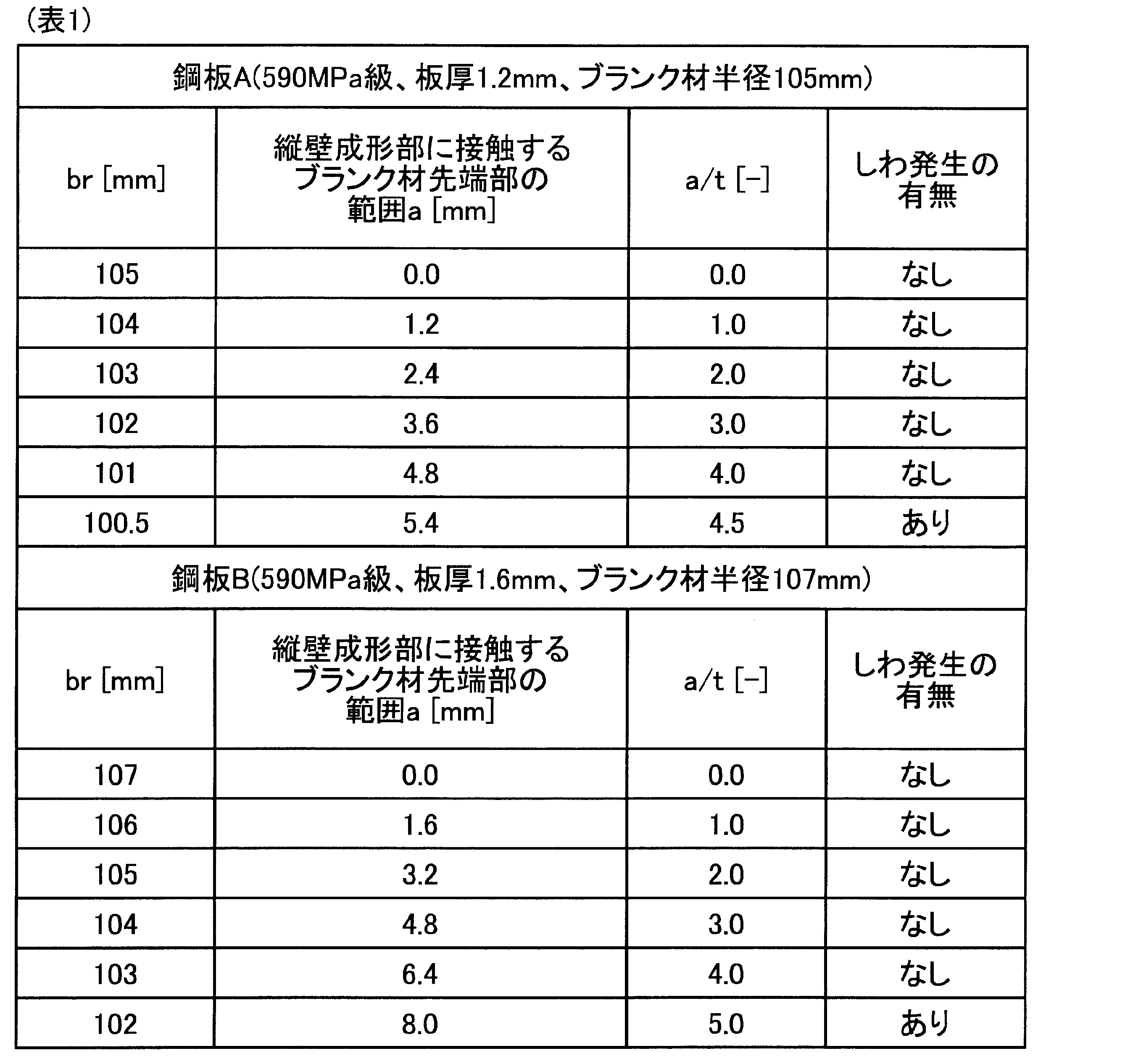
- the blank material 3 has a disk shape, and the radius (blank material radius) of the steel plate A is 105 [mm]. In the steel plate B, it was set to 107 [mm].
- the vertical wall forming portion 9a in which the cross-sectional shape is determined by giving a br smaller than the blank material radius of the blank material 3
- the front end portion including the portion entering inside from the front end of the blank material 3 is the vertical wall forming portion 9a.
- the larger the difference between the blank material radius of the blank material 3 and the br in the formula (2) the larger the range of the tip portion that the vertical wall forming portion 9a contacts.
- Table 1 shows that the steel plate A and the steel plate B are foam-formed under the above-described conditions, the presence or absence of wrinkles generated in the vertical wall portion 55 of the press-formed product 51, and the tip of the blank 3 that contacts the vertical wall forming portion 9a.
- required the range a of the part is shown.
- Example 2 uses a press-molding die 1 according to the present invention shown in FIG. 1 for a press-formed product 11 having a vertical wall portion 15 that curves in a convex shape in plan view toward the outside shown in FIG. It is the Example which verified the presence or absence of the wrinkle which generate
- the radius of curvature of the cross section of the connection portion 14 between the top plate portion 13 and the vertical wall portion 15 is 5 [mm]
- the curvature radius is 80 [mm].
- the blank 3 was a steel plate having a thickness of 1.2 [mm] and a tensile strength of 980 [MPa].
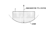
- the blank material radius of the blank material 3 is a curvature radius of the curve in the front-end
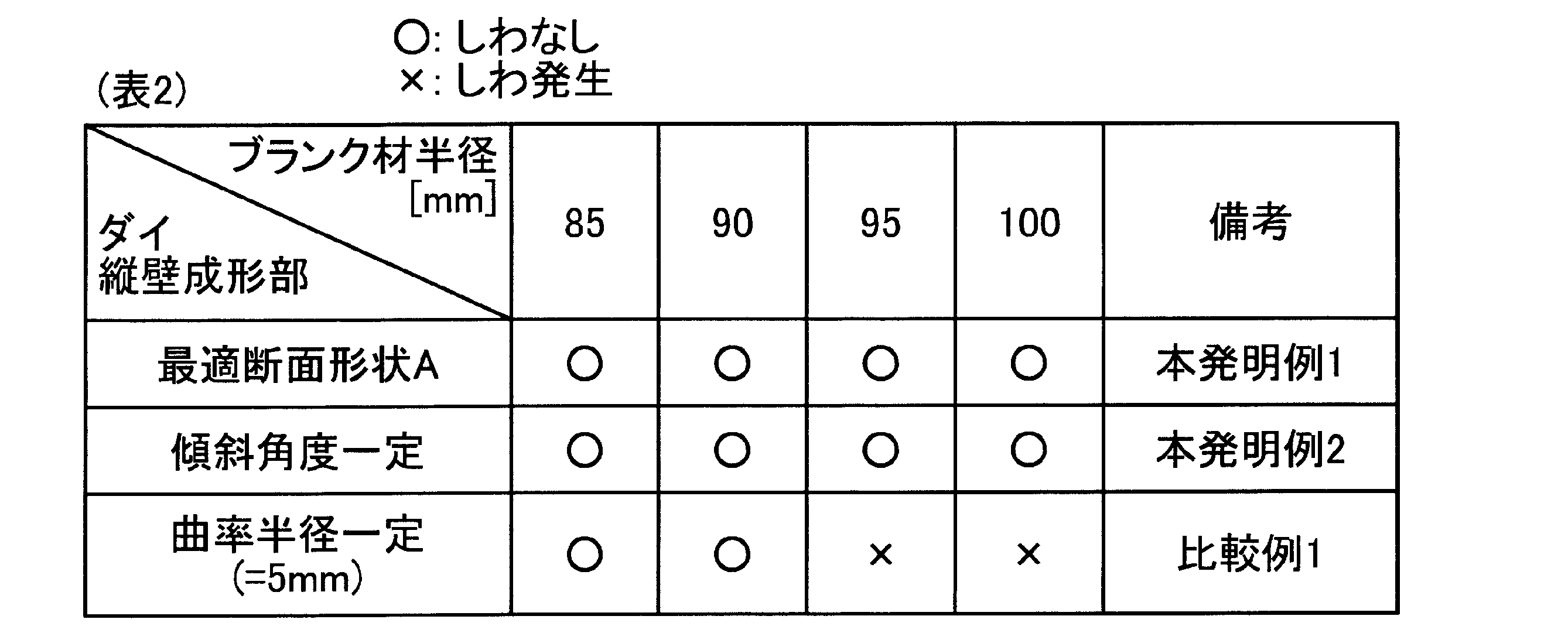
- Example 2 in addition to the press-molding die 1 (Invention Example 1) provided with the die 9 having the vertical wall molding portion 9a having the optimum cross-sectional shape A, the inclination angle is constant with respect to the horizontal direction as shown in FIG.
- the case where the blank material 3 with a different blank material radius is formed using each of the press-molding dies 21 (Comparative Example 1) provided with the conventional die 29 is a target.
- Example 2 the height h of the press-formed product 11 of the press-formed product 11 is changed in each of these cases, and the presence or absence of wrinkles is obtained.
- the results of Example 2 are shown in Table 2.
- Example 1 of the present invention was 80 [mm]
- the molding stroke in Example 2 of the present invention was 470 [mm].
- the vertical wall forming portion of the die is formed in a cross-sectional shape such that the tip of the blank material is always in contact with the die, and even if the height h of the press molded product is increased, the die is generated in the vertical wall portion 15 of the press molded product 11. It was demonstrated that wrinkles can be suppressed. Furthermore, it has been shown that the vertical wall portion 15 of the press-formed product 11 can be formed without greatly increasing the molding stroke by setting the vertical wall forming portion of the die to the optimum cross-sectional shape.
- Example 3 the press-molding die 1 according to the present invention is used to form the disk-shaped press-formed product 51 shown in FIG. 15 by foam molding, and wrinkles are generated in the vertical wall portion 55 of the press-formed product 51. It is the Example which verified the presence or absence of.
- the press-formed product 51 has a top plate portion 53 and a vertical wall portion 55.
- the top plate portion 53 and the vertical wall portion 55 are continuously connected by a connecting portion 54 that is an arcuate curved surface with a constant curvature.
- the height of the vertical wall portion 55 corresponds to the height of the press-formed product 51 (press-formed product height h).
- the press-formed product 51 was formed by a press-molding die 1 having a cross section shown in FIG. 1 using a steel plate having a thickness of 1.2 [mm] and a tensile strength of 590 [MPa] as a blank material 3.
- the radius r of the top plate portion 53 is 90 [mm]
- the radius of curvature of the connecting portion 54 between the top plate portion 53 and the vertical wall portion 55 is 8 [mm].
- Example 3 the two types of vertical wall forming portions 9a were studied.
- the present Example 3 shows the example which verified the effect of this invention by comparing with the case where it forms with the conventional press molding die 21 as shown in FIG.
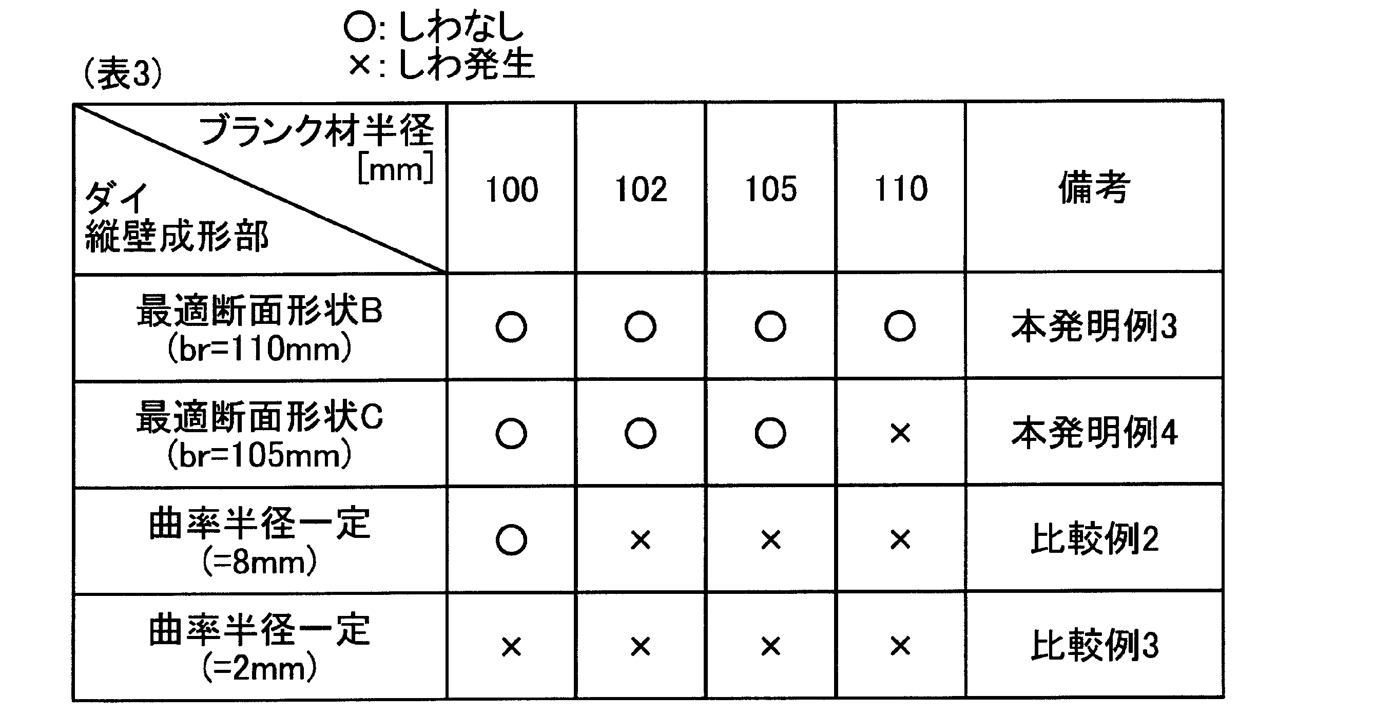
- the conventional press-molding dies 21 were of two types, one having a radius of curvature of the die shoulder portion 29b of 8 [mm] (Comparative Example 2) or 2 [mm] (Comparative Example 3).
- the vertical wall molding part 9a is the press molding die 1 (present invention example 3 or present invention example 4) or the conventional press molding die 21 (comparative example 2 or comparative example 3) having an optimal cross-sectional shape.
- the case where the blank material 3 having a different blank material radius is used to form is used.
- Example 3 the presence or absence of wrinkles in the vertical wall portion 55 of the obtained press-formed product 51 was confirmed.
- the results of Example 3 are shown in Table 3.
- the comparative example 2 having a large curvature radius has a slightly better wrinkle prevention effect than the comparative example 3 in which the curvature radius of the die shoulder portion 29b is 2 [mm], but the present invention example
- the press mold 1 having the vertical wall forming portion 9a having the optimal cross-sectional shape B or the optimal cross-sectional shape C shown in FIGS. 3 and 4 is used, the vertical direction of the press-formed product 51 is generated without generating wrinkles up to a larger blank material radius.
- the wall 55 could be press molded.
- the press molding method and the press mold according to the present invention are useful for foam molding of a press-molded product, and in particular, a vertical wall curved in a convex shape in plan view toward the outside of the press-molded product.
- the part is suitable for a press molding method and a press mold that can suppress the generation of wrinkles and can be easily molded in one step.
Landscapes
- Engineering & Computer Science (AREA)
- Mechanical Engineering (AREA)
- Shaping Metal By Deep-Drawing, Or The Like (AREA)
- Bending Of Plates, Rods, And Pipes (AREA)
Abstract
Description
本発明の実施の形態1に係るプレス成形方法は、図2に示すようにフランジ部を有さないプレス成形品11を、図1に示すプレス成形金型1を用いてフォーム成形するものである。詳細には、プレス成形品11は、図2に示すように、少なくとも天板部13と、天板部13に接続部14を介して連続する縦壁部15とを備え、縦壁部15の全体もしくは一部が外側に向かって平面視で凸状に湾曲したものである。本発明の実施の形態1に係るプレス成形方法は、図2に示すようなプレス成形品11を、図1に示すように、プレス成形金型1のパンチ5とパッド7とダイ9とでフォーム成形するプレス成形方法であって、ブランク材3の先端部をダイ9に常に接触させ、かつ、縦壁成形部9aにおいてはダイ9により該接触以外の拘束をしない状態でプレス成形品11の縦壁部15を成形するものである。以下、本実施の形態1に係るプレス成形方法により縦壁部15のしわの発生を抑制することができる理由を図2から図4に基づいて詳細に説明する。
本発明の実施の形態2に係るプレス成形金型1を、成形途中の状態を示す図1に基づいて説明する。本発明の実施の形態2に係るプレス成形金型1は、上述した実施の形態1と同様に図2に示すような、少なくとも天板部13と、天板部13に接続部14を介して連続する縦壁部15を有し、縦壁部15の全体もしくは一部が外側に向かって平面視で凸状に湾曲したプレス成形品11を成形するものである。プレス成形金型1は、図1に示すように、平板状のブランク材3の下面を支持するパンチ5と、パンチ5の天板成形部(forming top portion)5aで支持されたブランク材3の上面を押圧するパッド7と、パンチ5とパッド7とで挟持されたブランク材3に縦壁成形部9aが当接して曲げ加工を行うダイ9とを備えている。
パンチ5は、天板成形部5aと、天板成形部5aの端部から斜め下方に連続するパンチ肩部(shoulder portion of punch)5bと、パンチ肩部5bの下端側から下方に連続する縦壁成形部(forming wall portion)5cとを有している。天板成形部5aは、平坦面であるブランク材3の下面を支持する。また、パンチ肩部5bの断面形状は、曲率半径Rの円弧である。
パッド7は、パンチ5の天板成形部5aに対向するように配置され、昇降可能になっている。ブランク材3をパンチ5の天板成形部5aに載置し、パッド7をパンチ5側に移動させて押圧することで、パンチ5とパッド7とによりブランク材3を挟持することができる。
ダイ9は、ブランク材3に当接してブランク材3の曲げ加工をし、プレス成形品11の縦壁部15を成形する縦壁成形部9aを有している。縦壁成形部9aは、その断面形状が図1に示すような曲線である。縦壁成形部9aの断面形状を曲線とすることで、成形中においてブランク材3の先端部を常に縦壁成形部9aに接触させることができる。もしくは、後述するように、図5に示すような断面形状が直線である縦壁成形部39aを有するダイ39を用いても、成形中においてブランク材3の先端部を常に縦壁成形部39aに接触させることができる。


θ≦φ ・・・(1)
これより、縦壁成形部9aの高さ、すなわち成形ストロークをできる限り短くしたい場合、傾斜角度φが最小、すなわちθ=φの条件を満たせば良い。



3 ブランク材
5 パンチ
5a 天板成形部
5b パンチ肩部
5c 縦壁成形部
7 パッド
9 ダイ
9a 縦壁成形部
11 プレス成形品
13 天板部
14 接続部(connecting portion)
15 縦壁部
19 しわ
21 プレス成形金型(従来)
29 ダイ(従来)
29b ダイ肩部(従来)
31 プレス成形金型
39 ダイ
39a 縦壁成形部
41 基本ブランク材
43 小ブランク材
51 プレス成形品
53 天板部
54 接続部
55 縦壁部
Claims (5)
- フランジ部を有さないプレス成形品のプレス成形方法であって、少なくとも天板部と該天板部に接続部を介して連続する縦壁部を有し、該縦壁部の全体もしくは一部がプレス成形品の外側に向かって平面視で凸状に湾曲したプレス成形品をダイとパンチでフォーム成形するプレス成形方法であって、
ブランク材の先端部を前記ダイの縦壁成形部に常に接触させ、かつ、前記縦壁成形部においては前記ダイにより該接触以外の拘束をしない状態で前記縦壁部を成形することを特徴とするプレス成形方法。 - 前記ブランク材の先端部は、前記ブランク材の先端から板厚の4倍までの距離の範囲であることを特徴とする請求項1記載のプレス成形方法。
- 請求項1又は2に記載のプレス成形方法に用いるプレス成形金型であって、パンチとダイを有し、前記ダイの縦壁成形部の断面形状は、縦壁成形中においてブランク材の先端部が前記縦壁成形部に常に接触する形状であることを特徴とするプレス成形金型。
- 前記縦壁成形部の断面形状は、縦壁成形中において、前記ブランク材の先端から板厚の4倍までの距離の範囲が前記縦壁成形部に常に接触する形状であることを特徴とする請求項3記載のプレス成形金型。
- フランジ部を有さないプレス成形品であって、少なくとも天板部と該天板部に接続部を介して連続する縦壁部を有し、該縦壁部の全体もしくは一部がプレス成形品の外側に向かって平面視で凸状に湾曲した前記プレス成形品をフォーム成形するプレス成形金型であって、
ブランク材が載置される天板成形部と、該天板成形部に連続するとともに前記プレス成形品の前記湾曲に沿うパンチ肩部と、前記パンチ肩部に連続する縦壁成形部を有するパンチと、
該パンチに対して相対移動して前記プレス成形品の前記縦壁部を成形する縦壁成形部を有するダイを備え、
該ダイの前記縦壁成形部は、その断面形状が、
前記天板成形部上における前記湾曲の曲率半径の中心となる点を原点とし、水平方向をX軸、鉛直方向をY軸とするXY座標上において下式によって表される曲線を最適曲線とし、任意のX座標位置における前記最適曲線の接線の傾斜角度を最適傾斜角度としたとき、
前記X座標位置における接線の水平方向に対する傾斜角度が前記最適傾斜角度以上となる曲線で表されることを特徴とするプレス成形金型。

Priority Applications (5)
| Application Number | Priority Date | Filing Date | Title |
|---|---|---|---|
| KR1020177025627A KR102001328B1 (ko) | 2015-03-18 | 2016-01-27 | 프레스 성형 방법 및 프레스 성형 금형 |
| US15/552,615 US10500624B2 (en) | 2015-03-18 | 2016-01-27 | Press forming method and tool of press forming |
| EP16764534.0A EP3272437B1 (en) | 2015-03-18 | 2016-01-27 | Press-forming method and press-forming tool |
| MX2017011881A MX2017011881A (es) | 2015-03-18 | 2016-01-27 | Metodo de moldeo por prensa y herramienta de moldeo por prensa. |
| CN201680015831.3A CN107427884B (zh) | 2015-03-18 | 2016-01-27 | 冲压成型方法及冲压成型模具 |
Applications Claiming Priority (2)
| Application Number | Priority Date | Filing Date | Title |
|---|---|---|---|
| JP2015-054952 | 2015-03-18 | ||
| JP2015054952A JP5987942B1 (ja) | 2015-03-18 | 2015-03-18 | プレス成形金型 |
Publications (1)
| Publication Number | Publication Date |
|---|---|
| WO2016147703A1 true WO2016147703A1 (ja) | 2016-09-22 |
Family
ID=56871777
Family Applications (1)
| Application Number | Title | Priority Date | Filing Date |
|---|---|---|---|
| PCT/JP2016/052300 Ceased WO2016147703A1 (ja) | 2015-03-18 | 2016-01-27 | プレス成形(press forming)方法及びプレス成形金型(tool of press forming) |
Country Status (7)
| Country | Link |
|---|---|
| US (1) | US10500624B2 (ja) |
| EP (1) | EP3272437B1 (ja) |
| JP (1) | JP5987942B1 (ja) |
| KR (1) | KR102001328B1 (ja) |
| CN (1) | CN107427884B (ja) |
| MX (1) | MX2017011881A (ja) |
| WO (1) | WO2016147703A1 (ja) |
Families Citing this family (7)
| Publication number | Priority date | Publication date | Assignee | Title |
|---|---|---|---|---|
| CA3011213C (en) * | 2016-01-26 | 2020-05-12 | Nippon Steel Corporation | A pressing machine and a method for manufacturing a press-formed product |
| US11383286B2 (en) | 2018-02-28 | 2022-07-12 | Jfe Steel Corporation | Metal sheet for press forming, press forming device, and production method for pressed component |
| JP6919690B2 (ja) * | 2018-12-06 | 2021-08-18 | Jfeスチール株式会社 | プレス部品の製造方法及び下金型の設計方法 |
| JP7207276B2 (ja) * | 2019-11-20 | 2023-01-18 | Jfeスチール株式会社 | プレス成形金型 |
| CN115214782B (zh) * | 2021-04-16 | 2023-08-15 | 广州汽车集团股份有限公司 | 一种侧围a柱末端结构 |
| CN113319172B (zh) * | 2021-05-11 | 2022-10-28 | 中国第一汽车股份有限公司 | 一种消除高强板冲压件翻边立壁弯曲的方法 |
| WO2024006051A1 (en) | 2022-06-30 | 2024-01-04 | Cleveland-Cliffs Steel Properties Inc. | Method for prevention of premature edge fracture at draw bead |
Citations (4)
| Publication number | Priority date | Publication date | Assignee | Title |
|---|---|---|---|---|
| US2321344A (en) * | 1939-03-04 | 1943-06-08 | Remington Arms Co Inc | Projectile |
| JPS5217363A (en) * | 1975-06-25 | 1977-02-09 | Ishizuka Seiki Kk | Method of making metallic drive plugs |
| JPH04147718A (ja) * | 1990-10-12 | 1992-05-21 | Nissan Motor Co Ltd | プレス型 |
| WO2014132545A1 (ja) * | 2013-02-28 | 2014-09-04 | Jfeスチール株式会社 | プレス成形方法 |
Family Cites Families (12)
| Publication number | Priority date | Publication date | Assignee | Title |
|---|---|---|---|---|
| JPH0647135B2 (ja) | 1988-03-11 | 1994-06-22 | 日新製鋼株式会社 | 角部に円弧状部を有する金属製品の製造法 |
| JPH0647135A (ja) | 1992-07-30 | 1994-02-22 | Sophia Co Ltd | 遊技機 |
| JP2003120463A (ja) * | 2001-10-16 | 2003-04-23 | Hitachi Ltd | 燃料噴射弁、ノズルボディ、流体通路を有する円筒部品の製造方法 |
| JP2005095937A (ja) * | 2003-09-25 | 2005-04-14 | Toyota Auto Body Co Ltd | プレス型及びプレス方法 |
| JP2005254279A (ja) | 2004-03-11 | 2005-09-22 | Toyota Auto Body Co Ltd | プレス型 |
| JP2008200709A (ja) * | 2007-02-20 | 2008-09-04 | Nissan Motor Co Ltd | プレス成形品の製造装置、プレス成形品の製造方法、およびプレス成形品 |
| DE102008034996B4 (de) * | 2008-07-25 | 2010-11-18 | Benteler Automobiltechnik Gmbh | Vorrichtung zum Warmformen, Presshärten und Schneiden eines Halbzeugs aus härtbarem Stahl |
| JP5199805B2 (ja) * | 2008-09-24 | 2013-05-15 | 東プレ株式会社 | ダイクエンチ加工製品とその製造方法及び製造装置 |
| CN103237611B (zh) | 2010-11-24 | 2015-06-24 | 新日铁住金株式会社 | L形产品的制造方法 |
| JP5808297B2 (ja) * | 2012-06-27 | 2015-11-10 | Jfeスチール株式会社 | プレス成形方法、プレス成形装置 |
| KR101644765B1 (ko) | 2013-01-09 | 2016-08-01 | 신닛테츠스미킨 카부시키카이샤 | 프레스 성형 방법 |
| JP5664810B1 (ja) | 2013-06-27 | 2015-02-04 | Jfeスチール株式会社 | プレス成形方法及び装置 |
-
2015
- 2015-03-18 JP JP2015054952A patent/JP5987942B1/ja active Active
-
2016
- 2016-01-27 EP EP16764534.0A patent/EP3272437B1/en active Active
- 2016-01-27 KR KR1020177025627A patent/KR102001328B1/ko active Active
- 2016-01-27 CN CN201680015831.3A patent/CN107427884B/zh active Active
- 2016-01-27 WO PCT/JP2016/052300 patent/WO2016147703A1/ja not_active Ceased
- 2016-01-27 US US15/552,615 patent/US10500624B2/en active Active
- 2016-01-27 MX MX2017011881A patent/MX2017011881A/es unknown
Patent Citations (4)
| Publication number | Priority date | Publication date | Assignee | Title |
|---|---|---|---|---|
| US2321344A (en) * | 1939-03-04 | 1943-06-08 | Remington Arms Co Inc | Projectile |
| JPS5217363A (en) * | 1975-06-25 | 1977-02-09 | Ishizuka Seiki Kk | Method of making metallic drive plugs |
| JPH04147718A (ja) * | 1990-10-12 | 1992-05-21 | Nissan Motor Co Ltd | プレス型 |
| WO2014132545A1 (ja) * | 2013-02-28 | 2014-09-04 | Jfeスチール株式会社 | プレス成形方法 |
Also Published As
| Publication number | Publication date |
|---|---|
| JP2016175087A (ja) | 2016-10-06 |
| KR20170117495A (ko) | 2017-10-23 |
| MX2017011881A (es) | 2018-06-07 |
| CN107427884A (zh) | 2017-12-01 |
| EP3272437B1 (en) | 2019-11-13 |
| EP3272437A1 (en) | 2018-01-24 |
| US20180021831A1 (en) | 2018-01-25 |
| US10500624B2 (en) | 2019-12-10 |
| JP5987942B1 (ja) | 2016-09-07 |
| CN107427884B (zh) | 2019-09-03 |
| EP3272437A4 (en) | 2018-11-21 |
| KR102001328B1 (ko) | 2019-07-17 |
Similar Documents
| Publication | Publication Date | Title |
|---|---|---|
| JP5836972B2 (ja) | L形製品の製造方法 | |
| JP5987942B1 (ja) | プレス成形金型 | |
| JP5962774B2 (ja) | プレス成形品の製造方法 | |
| JP6011680B1 (ja) | プレス成形方法及びプレス成形金型 | |
| KR20160043105A (ko) | 프레스 성형품 및 프레스 성형품의 제조 방법 및 프레스 성형품의 제조 장치 | |
| WO2016132905A1 (ja) | プレス成形方法及びプレス成形金型 | |
| CN110087791A (zh) | 冲压成形方法 | |
| WO2021181982A1 (ja) | プレス部品の製造方法、プレス成形用の金属板、及び高張力鋼板 | |
| CN104936717B (zh) | 具有立体边缘的金属部件的制造方法以及制造用模具 | |
| WO2021205692A1 (ja) | プレス成形方法及びプレス成形品 | |
| JP6923043B1 (ja) | プレス成形方法 | |
| JP6112226B2 (ja) | プレス成形方法、及びプレス成形部品の製造方法 | |
| CN107921504A (zh) | 拉伸凸缘成形零件的制造方法 | |
| CN113727791A (zh) | 冲压成型方法 | |
| US20220055085A1 (en) | Press forming method | |
| CN113766980B (zh) | 冲压成型方法 | |
| WO2022113412A1 (ja) | プレス成形方法 | |
| JP6897840B1 (ja) | プレス成形方法 | |
| JP6966729B1 (ja) | プレス成形品 | |
| KR20200050197A (ko) | 경사벽부의 주름을 없앨 수 있는 프레스 성형 방법 | |
| JP6969133B2 (ja) | 伸びフランジを有する成形体及びその製造方法 | |
| WO2026058765A1 (ja) | プレス成形品の製造方法およびプレス金型 | |
| CN118715070A (zh) | 冲压成型方法以及冲压成型品的制造方法 | |
| JP2021169119A (ja) | プレス部品の製造方法、プレス成形用の金属板、及び高張力鋼板 |
Legal Events
| Date | Code | Title | Description |
|---|---|---|---|
| 121 | Ep: the epo has been informed by wipo that ep was designated in this application |
Ref document number: 16764534 Country of ref document: EP Kind code of ref document: A1 |
|
| WWE | Wipo information: entry into national phase |
Ref document number: 15552615 Country of ref document: US |
|
| REEP | Request for entry into the european phase |
Ref document number: 2016764534 Country of ref document: EP |
|
| ENP | Entry into the national phase |
Ref document number: 20177025627 Country of ref document: KR Kind code of ref document: A |
|
| WWE | Wipo information: entry into national phase |
Ref document number: MX/A/2017/011881 Country of ref document: MX |
|
| NENP | Non-entry into the national phase |
Ref country code: DE |