WO2016148048A1 - Bague d'étanchéité - Google Patents
Bague d'étanchéité Download PDFInfo
- Publication number
- WO2016148048A1 WO2016148048A1 PCT/JP2016/057718 JP2016057718W WO2016148048A1 WO 2016148048 A1 WO2016148048 A1 WO 2016148048A1 JP 2016057718 W JP2016057718 W JP 2016057718W WO 2016148048 A1 WO2016148048 A1 WO 2016148048A1
- Authority
- WO
- WIPO (PCT)
- Prior art keywords
- groove
- seal ring
- dynamic pressure
- pressure generating
- present
- Prior art date
- Legal status (The legal status is an assumption and is not a legal conclusion. Google has not performed a legal analysis and makes no representation as to the accuracy of the status listed.)
- Ceased
Links
Images















Classifications
-
- F—MECHANICAL ENGINEERING; LIGHTING; HEATING; WEAPONS; BLASTING
- F16—ENGINEERING ELEMENTS AND UNITS; GENERAL MEASURES FOR PRODUCING AND MAINTAINING EFFECTIVE FUNCTIONING OF MACHINES OR INSTALLATIONS; THERMAL INSULATION IN GENERAL
- F16J—PISTONS; CYLINDERS; SEALINGS
- F16J15/00—Sealings
- F16J15/16—Sealings between relatively-moving surfaces
- F16J15/164—Sealings between relatively-moving surfaces the sealing action depending on movements; pressure difference, temperature or presence of leaking fluid
-
- F—MECHANICAL ENGINEERING; LIGHTING; HEATING; WEAPONS; BLASTING
- F16—ENGINEERING ELEMENTS AND UNITS; GENERAL MEASURES FOR PRODUCING AND MAINTAINING EFFECTIVE FUNCTIONING OF MACHINES OR INSTALLATIONS; THERMAL INSULATION IN GENERAL
- F16J—PISTONS; CYLINDERS; SEALINGS
- F16J15/00—Sealings
- F16J15/16—Sealings between relatively-moving surfaces
- F16J15/32—Sealings between relatively-moving surfaces with elastic sealings, e.g. O-rings
- F16J15/3268—Mounting of sealing rings
- F16J15/3272—Mounting of sealing rings the rings having a break or opening, e.g. to enable mounting on a shaft otherwise than from a shaft end
-
- F—MECHANICAL ENGINEERING; LIGHTING; HEATING; WEAPONS; BLASTING
- F16—ENGINEERING ELEMENTS AND UNITS; GENERAL MEASURES FOR PRODUCING AND MAINTAINING EFFECTIVE FUNCTIONING OF MACHINES OR INSTALLATIONS; THERMAL INSULATION IN GENERAL
- F16J—PISTONS; CYLINDERS; SEALINGS
- F16J15/00—Sealings
- F16J15/44—Free-space packings
- F16J15/441—Free-space packings with floating ring
Definitions
- the present invention relates to a seal ring that seals an annular gap between a shaft and a shaft hole of a housing.
- Patent Document 2 A technique is also known in which a groove communicating from the inner peripheral surface side to the outer peripheral surface side is provided on the sliding surface side of the seal ring so that foreign matters are excluded from the sliding surface of the seal ring.
- Patent Document 2 A technique is also known in which a groove communicating from the inner peripheral surface side to the outer peripheral surface side is provided on the sliding surface side of the seal ring so that foreign matters are excluded from the sliding surface of the seal ring.
- An object of the present invention is to provide a seal ring that can stably reduce rotational torque while suppressing leakage of a fluid to be sealed.
- the present invention employs the following means in order to solve the above problems.
- the seal ring of the present invention is Fluid pressure in a region to be sealed, which is mounted in an annular groove provided on the outer periphery of the shaft, and is configured to seal the annular gap between the shaft and the housing that rotate relatively to change the fluid pressure.
- a groove having a second groove leading into the groove is provided;
- the first groove includes a dynamic pressure generating groove configured such that the groove bottom is shallower at the end in the circumferential direction than the center in the circumferential direction, and the groove bottom is more than the groove bottom of the dynamic pressure generating groove. Deeper, with a foreign material catching groove that can catch foreign matter, A 1st groove
- channel is provided in the position settled in the sliding area
- the fluid to be sealed since the fluid to be sealed is guided into the groove portion, the fluid pressure acting on the seal ring from the high pressure side and the pressure ring acting on the seal ring from the low pressure side in the range where the groove portion is provided. Fluid pressure is offset. Thereby, the pressure receiving area of the fluid pressure with respect to the seal ring can be reduced. Further, when the seal ring slides with respect to the low-pressure side wall surface in the annular groove, dynamic pressure is generated by the fluid to be sealed flowing out from the dynamic pressure generating groove to the sliding portion. Thereby, the force of the direction away from a side wall surface with respect to a seal ring generate
- the groove bottom of the dynamic pressure generating groove is configured so that the end in the circumferential direction is shallower than the center in the circumferential direction, so that the above dynamic pressure is effectively generated by the wedge effect. Can be made.
- the rotational torque can be effectively reduced by combining the reduction of the pressure receiving area and the generation of force in the direction away from the side wall surface with respect to the seal ring due to the dynamic pressure. Become.
- the dynamic pressure generating function by the dynamic pressure generating groove is also prevented from being damaged by the foreign matter. Furthermore, since the 1st groove
- the dynamic pressure generating grooves may be provided on both sides of the center in the circumferential direction in the first groove.
- the foreign matter capturing groove is provided over the entire circumferential region in the first groove.
- the groove bottom of the foreign matter capturing groove may be configured to gradually become shallower toward the second groove.
- the foreign matter that has entered from the second groove can be efficiently guided to the foreign matter capturing groove, and the foreign matter can be prevented from entering the dynamic pressure generating groove.
- the dynamic pressure generating groove is provided so that the radial width increases toward the end in the circumferential direction.
- the groove bottom of the second groove is preferably deeper than the groove bottom of the dynamic pressure generating groove and set to a depth capable of capturing foreign matter.
- the seal ring of the present invention is Fluid pressure in a region to be sealed, which is mounted in an annular groove provided on the outer periphery of the shaft, and is configured to seal the annular gap between the shaft and the housing that rotate relatively to change the fluid pressure.
- a seal ring for holding In the seal ring that slides against the side wall surface on the low pressure side in the annular groove On the sliding surface side that slides against the side wall surface, A first groove extending in the circumferential direction, provided at a position within a sliding region that slides relative to the side wall surface; A second groove that extends from the inner peripheral surface to a position that enters the central position in the circumferential direction of the first groove, guides the fluid to be sealed into the first groove, and discharges foreign matter to the inner peripheral surface side; Is provided,
- the first groove has a pair of grooves configured so that the groove bottom is shallower at the circumferential end than at the circumferential center on both sides in the circumferential direction across the portion where the second groove has entered.
- the seal ring since the fluid to be sealed is guided into the first groove and the second groove provided on the sliding surface side of the seal ring, in the range where these are provided, the seal ring is changed from the high pressure side.
- the fluid pressure acting on the seal ring cancels out the fluid pressure acting on the seal ring from the low pressure side. Thereby, the pressure receiving area of the fluid pressure with respect to the seal ring can be reduced.
- the seal ring slides with respect to the low-pressure side wall surface in the annular groove, dynamic pressure is generated by the fluid to be sealed flowing out from the dynamic pressure generating groove to the sliding portion. Thereby, the force of the direction away from a side wall surface with respect to a seal ring generate
- the groove bottom of the dynamic pressure generating groove is configured so that the end in the circumferential direction is shallower than the center in the circumferential direction, so that the above dynamic pressure is effectively generated by the wedge effect.
- the rotational torque can be effectively reduced by combining the reduction of the pressure receiving area and the generation of force in the direction away from the side wall surface with respect to the seal ring due to the dynamic pressure.
- the dynamic pressure generating grooves are provided on both sides in the circumferential direction across the portion where the second groove enters, the dynamic pressure generating function can be exhibited regardless of the rotation direction of the seal ring with respect to the shaft. Can do.
- channel is provided in the position settled in the sliding area
- a second groove deeper than the groove bottom of the dynamic pressure generating groove is provided, and foreign matter that has entered the sliding portion can be discharged to the inner peripheral surface side by the second groove. Accordingly, it is possible to prevent the dynamic pressure generating function by the dynamic pressure generating groove from being damaged by the foreign matter.
- a barrier between the pair of dynamic pressure generating grooves and outside the second groove in a radial direction that prevents the flow of the fluid to be sealed from one dynamic pressure generating groove to the other dynamic pressure generating groove A part may be provided.
- the groove bottom of the second groove is preferably constituted by a stepped step surface in which the groove depth increases from the radially outer side toward the inner side.
- the groove bottom of the second groove is provided with an inclined surface whose groove depth increases from the outside in the radial direction toward the inside.
- FIG. 1 is a side view of a seal ring according to Embodiment 1 of the present invention.
- FIG. 2 is a partially enlarged view of a side view of the seal ring according to Embodiment 1 of the present invention.
- FIG. 3 is a partially enlarged view of a side view of the seal ring according to Embodiment 1 of the present invention.
- FIG. 4 is a partially enlarged view of the seal ring according to Embodiment 1 of the present invention as viewed from the outer peripheral surface side.
- FIG. 5 is a partially enlarged view of the seal ring according to Embodiment 1 of the present invention as viewed from the inner peripheral surface side.
- FIG. 1 is a side view of a seal ring according to Embodiment 1 of the present invention.
- FIG. 2 is a partially enlarged view of a side view of the seal ring according to Embodiment 1 of the present invention.
- FIG. 3 is a partially enlarged view of a side view of the seal ring
- FIG. 6 is a schematic cross-sectional view showing a state in use of the seal ring according to Embodiment 1 of the present invention.
- FIG. 7 is a partially enlarged view of a side view of the seal ring according to the first embodiment of the present invention.
- FIG. 8 is a schematic cross-sectional view of the seal ring according to the first embodiment of the present invention.
- FIG. 9 is a schematic cross-sectional view of a seal ring according to Embodiment 1 of the present invention.
- FIG. 10 is a partially enlarged view of a side view of the seal ring according to the second embodiment of the present invention.
- FIG. 11 is a partially enlarged view of a side view of a seal ring according to Embodiment 3 of the present invention.
- FIG. 12 is a partially enlarged view of a side view of a seal ring according to Embodiment 4 of the present invention.
- FIG. 13 is a partially enlarged view of a side view of a seal ring according to Embodiment 5 of the present invention.
- FIG. 14 is a partially enlarged view of a side view of a seal ring according to Embodiment 6 of the present invention.
- FIG. 15 is a partially enlarged view of a side view of a seal ring according to Embodiment 7 of the present invention.
- FIG. 16 is a schematic cross-sectional view of a seal ring according to Embodiment 7 of the present invention.
- FIG. 17 is a partially enlarged view of a side view of the seal ring according to the eighth embodiment of the present invention.
- FIG. 18 is a schematic cross-sectional view of a seal ring according to Example 8 of the present invention.
- FIG. 19 is a partially enlarged view of a side view of a seal ring according to Embodiment 9 of the present invention.
- FIG. 20 is a partially enlarged view of a side view of a seal ring according to Embodiment 10 of the present invention.
- FIG. 21 is a side view of a seal ring according to Embodiment 2 of the present invention.
- FIG. 22 is a partially enlarged view of a side view of a seal ring according to Embodiment 2 of the present invention.
- FIG. 23 is a partially enlarged view of a side view of a seal ring according to Embodiment 2 of the present invention.
- FIG. 19 is a schematic cross-sectional view of a seal ring according to Example 8 of the present invention.
- FIG. 19 is a partially enlarged view of a side view of a seal ring according to Embodiment 9
- FIG. 24 is a partially enlarged view of the seal ring according to the second embodiment of the present invention as viewed from the outer peripheral surface side.
- FIG. 25 is a partially enlarged view of the seal ring according to the second embodiment of the present invention as viewed from the inner peripheral surface side.
- FIG. 26 is a partially enlarged view of a side view of a seal ring according to Embodiment 2 of the present invention.
- FIG. 27 is a schematic cross-sectional view of a seal ring according to Embodiment 2 of the present invention.
- FIG. 28 is a schematic cross-sectional view showing a state when the seal ring according to the second embodiment of the present invention is used.
- FIG. 29 is a schematic cross-sectional view showing a state in use of the seal ring according to the second embodiment of the present invention.
- FIG. 30 is a partially enlarged view of a side view of a seal ring according to Embodiment 11 of the present invention.
- FIG. 31 is a schematic sectional view of a seal ring according to Example 11 of the present invention.
- FIG. 32 is a schematic cross-sectional view of a seal ring according to Example 11 of the present invention.
- FIG. 33 is a schematic sectional view of a seal ring according to Example 11 of the present invention.
- FIG. 34 is a partially enlarged view of a side view of a seal ring according to Embodiment 12 of the present invention.
- FIG. 35 is a schematic sectional view of a seal ring according to Embodiment 12 of the present invention.
- FIG. 36 is a schematic sectional view of a seal ring according to Embodiment 12 of the present invention.
- FIG. 37 is a schematic sectional view of a seal ring according to Embodiment 12 of the present invention.
- FIG. 38 is a partially enlarged view of a side view of a seal ring according to Embodiment 13 of the present invention.
- FIG. 39 is a partially enlarged view of a side view of a seal ring according to Embodiment 14 of the present invention.
- FIG. 40 is a schematic sectional view of a seal ring according to Example 14 of the present invention.
- FIG. 41 is a schematic sectional view of a seal ring according to Embodiment 14 of the present invention.
- FIG. 42 is a schematic sectional view of a seal ring according to Embodiment 14 of the present invention.
- FIG. 43 is a partially enlarged view of a side view of a seal ring according to Embodiment 15 of the present invention.
- FIG. 44 is a schematic sectional view of a seal ring according to Embodiment 15 of the present invention.
- FIG. 45 is a schematic sectional view of a seal ring according to Example 15 of the present invention.
- FIG. 46 is a schematic sectional view of a seal ring according to a modification of the fifteenth embodiment of the present invention.
- FIG. 1 is a side view of a seal ring according to Embodiment 1 of the present invention.
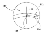
- FIG. 2 is a partially enlarged view of a side view of the seal ring according to the first embodiment of the present invention, and is an enlarged view of a circled portion in FIG.
- FIG. 3 is a partially enlarged view of a side view of the seal ring according to the first embodiment of the present invention, and is an enlarged view of a circled portion in FIG. 1 as viewed from the opposite side.
- FIG. 4 is a partially enlarged view of the seal ring according to the first embodiment of the present invention as viewed from the outer peripheral surface side, and is an enlarged view of a circled portion in FIG. 1 as viewed from the outer peripheral surface side.
- FIG. 5 is a partially enlarged view of the seal ring according to the first embodiment of the present invention as viewed from the inner peripheral surface side, and is an enlarged view of the circled portion in FIG. 1 as viewed from the inner peripheral surface side.
- FIG. 6 is a schematic cross-sectional view showing a state in use of the seal ring according to Embodiment 1 of the present invention.
- the seal ring 100 is mounted in an annular groove 210 provided on the outer periphery of the shaft 200, and rotates relative to the shaft 200 and the housing 300 (the inner periphery of the shaft hole through which the shaft 200 in the housing 300 is inserted.
- the annular gap between the first and second surfaces is sealed.
- the seal ring 100 maintains the fluid pressure in the region to be sealed configured so that the fluid pressure (hydraulic pressure in the present embodiment) changes.
- the fluid pressure in the region on the right side of the seal ring 100 in FIG. 6 is configured to change.
- the seal ring 100 plays a role of holding the fluid pressure in the region to be sealed on the right side in the drawing via the seal ring 100.
- the fluid pressure in the sealing target region is low and no load is applied.
- the fluid pressure in the sealing target region increases.
- the left side shows an unloaded state
- the right side shows a state in which a differential pressure is generated (a state in which the fluid pressure in the region to be sealed is increased).
- the seal ring 100 is made of a resin material such as polyetheretherketone (PEEK), polyphenylene sulfide (PPS), polytetrafluoroethylene (PTFE). Further, the peripheral length of the outer peripheral surface of the seal ring 100 is configured to be shorter than the peripheral length of the inner peripheral surface of the shaft hole of the housing 300 and is configured not to have a tightening allowance. Therefore, in a state where the fluid pressure is not acting, the outer peripheral surface of the seal ring 100 can be in a state separated from the inner peripheral surface of the housing 300 (see the left side in FIG. 6).
- PEEK polyetheretherketone
- PPS polyphenylene sulfide
- PTFE polytetrafluoroethylene
- the seal ring 100 is provided with an abutment portion 110 at one place in the circumferential direction.
- a groove 120 is provided on the sliding surface side of the seal ring 100.
- the seal ring 100 according to the present embodiment has a configuration in which the above-described joint portion 110 and a plurality of groove portions 120 are formed on an annular member having a rectangular cross section.
- this is merely a description of the shape, and does not necessarily mean that the annular member having a rectangular cross section is used as a material to perform the process of forming the joint portion 110 and the plurality of groove portions 120.
- the plurality of groove portions 120 may be obtained by cutting, and the manufacturing method is not particularly limited.
- the configuration of the joint portion 110 according to the present embodiment will be described with reference to FIGS. 2 to 5 in particular.
- the joint part 110 according to the present embodiment employs a special step cut that is cut in a step shape when viewed from either the outer peripheral surface side or both side wall surfaces.
- the first fitting convex portion 111 and the first fitting concave portion 114 are provided on the outer peripheral surface side on one side via the cutting portion, and the outer peripheral surface side on the other side is provided.
- a second fitting concave portion 113 into which the first fitting convex portion 111 is fitted and a second fitting convex portion 112 to be fitted into the first fitting concave portion 114 are provided.
- the end surface 115 on the inner peripheral surface side on one side and the end surface 116 on the inner peripheral side on the other side face each other through the cutting portion.
- the “cutting portion” includes not only the case of being cut by cutting, but also the case of being obtained by molding.
- the case of the special step cut is shown as an example of the abutment portion 110, but the abutment portion 110 is not limited to this, and a straight cut, a bias cut, a step cut, or the like may be employed.
- a low-elasticity material such as PTFE
- the end portion may be provided without providing the joint portion 110.
- a plurality of groove portions 120 are provided at equal intervals over the entire circumference excluding the vicinity of the joint portion 110 in the side surface on the sliding surface side of the seal ring 100 (see FIG. 1).
- the plurality of grooves 120 are provided to generate dynamic pressure when the seal ring 100 slides with respect to the low-pressure side (L) side wall surface 211 of the annular groove 210 provided in the shaft 200.
- the groove 120 has a first groove extending in the circumferential direction and a second groove extending from the circumferential center position of the first groove to the inner circumferential surface and guiding the fluid to be sealed into the first groove. is doing.
- the first groove includes a dynamic pressure generating groove configured such that the groove bottom is shallower at the end in the circumferential direction than the center in the circumferential direction, and the groove bottom is a groove of the dynamic pressure generating groove. Deeper than the bottom, it has a foreign matter catching groove capable of catching foreign matter. Further, the first groove is provided at a position that fits within the sliding region X where the seal ring 100 slides relative to the low-pressure side (L) side wall surface 211.
- the annular gap between the relatively rotating shaft 200 and the housing 300 is sealed, and the fluid pressure in the region to be sealed (the region on the high pressure side (H)) configured to change the fluid pressure. Can be held.
- the shaft 200 and the housing 300 are relatively rotated, the shaft 200 slides between the side wall surface 211 on the low pressure side (L) of the annular groove 210 and the seal ring 100.
- dynamic pressure is generated when the fluid to be sealed flows out from the dynamic pressure generating groove in the groove 120 provided on the side surface on the sliding surface side of the seal ring 100 to the sliding portion.
- the fluid to be sealed flows from the end portion on the counterclockwise direction side of the dynamic pressure generating groove to the sliding portion. To do. Further, when the seal ring 100 rotates counterclockwise in FIG. 1 with respect to the annular groove 210, the fluid to be sealed flows out from the end portion on the clockwise direction side of the dynamic pressure generating groove to the sliding portion. To do.
- the seal ring 100 slides with respect to the low pressure side (L) side wall surface 211 in the annular groove 210, dynamic pressure is generated by the fluid to be sealed flowing out from the dynamic pressure generating groove to the sliding portion. To do. Thereby, a force in a direction away from the side wall surface 211 is generated with respect to the seal ring 100.
- the groove bottom of the dynamic pressure generating groove is configured so that the end in the circumferential direction is shallower than the center in the circumferential direction, so that the above dynamic pressure is effectively generated by the wedge effect. Can be made.
- the dynamic pressure generating function by the dynamic pressure generating groove is also prevented from being damaged by the foreign matter. That is, it is possible to suppress foreign matter from being caught between the dynamic pressure generating groove and the side wall surface 211. Thereby, it can suppress that a dynamic pressure effect will be reduced, and can suppress that wear is accelerated
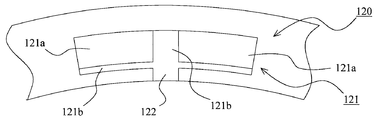
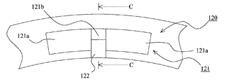
- FIG. 7 is a partially enlarged view of a side view of the seal ring according to the first embodiment of the present invention, and is an enlarged view of the vicinity where the groove 120 is provided.
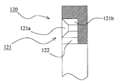
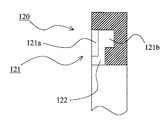
- FIG. 8 is a schematic cross-sectional view of the seal ring according to the first embodiment of the present invention, which is a cross-sectional view along AA in FIG.
- FIG. 9 is a schematic cross-sectional view of the seal ring according to the first embodiment of the present invention, and is a BB cross-sectional view in FIG.
- the groove portion 120 is provided on the sliding surface side of the seal ring 100.
- the groove part 120 according to the present embodiment extends from the circumferential center of the first groove 121 to the inner peripheral surface of the first groove 121 extending in the circumferential direction, and guides the fluid to be sealed into the first groove 121.
- the second groove 122 is configured.
- the first groove 121 is configured so that the radial width is constant. As described in the above embodiment, the first groove 121 is provided at a position that fits within the sliding region X where the seal ring 100 slides with respect to the low-pressure side (L) side wall surface 211 of the annular groove 210. ing.
- the first groove 121 includes a dynamic pressure generating groove 121a configured such that the groove bottom is shallower at the end in the circumferential direction than the center in the circumferential direction, and the groove bottom has a dynamic pressure generating groove 121a.
- the foreign material capturing groove 121b is deeper than the groove bottom and capable of capturing the foreign material.
- the dynamic pressure generating groove 121a is provided on each side of the first groove 121 with respect to the center in the circumferential direction.
- the pair of dynamic pressure generating grooves 121a is configured to gradually become shallower from the circumferential center to the circumferential end.
- the groove bottoms of the pair of dynamic pressure generating grooves 121a are constituted by flat inclined surfaces.
- the pair of dynamic pressure generating grooves 121a is configured so that the radial width gradually increases from the center in the circumferential direction toward the end in the circumferential direction.
- the pair of dynamic pressure generating grooves 121a is configured such that the planar shape thereof is a trapezoid.
- the foreign matter capturing groove 121b is provided in the first groove 121 over the entire region in the circumferential direction. More specifically, the foreign matter capturing groove 121b is provided in a central portion in the circumferential direction in the first groove 121 and in a portion on the inner peripheral surface side and outer peripheral surface side of the pair of dynamic pressure generating grooves 121a. Yes.
- the groove bottom of the second groove 122 is set deeper than the groove bottom of the dynamic pressure generating groove 121a and set to a depth capable of catching foreign matter. More specifically, the depth of the groove bottom of the second groove 122 and the depth of the groove bottom of the foreign matter capturing groove 121b are set to be the same.
- the dynamic pressure generating grooves 121a are provided on both sides of the center in the circumferential direction in the first groove 121, respectively, so that it relates to the rotational direction of the seal ring 100 relative to the shaft 200.
- the dynamic pressure generating function by the dynamic pressure generating groove 121a can be exhibited.
- the dynamic pressure generating groove 121a is provided so that the radial width increases toward the end in the circumferential direction, the diameter of the fluid to be sealed that flows out from the dynamic pressure generating groove 121a to the sliding portion. The width of the direction can be widened.
- the groove bottom of the second groove 121b is set deeper than the groove bottom of the dynamic pressure generating groove 121a so as to capture foreign matter. Therefore, the second groove 122 also exhibits a function of capturing foreign matter, and can further suppress the foreign matter from entering the dynamic pressure generating groove 121a.
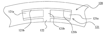
- FIG. 10 shows a second embodiment of the present invention. This embodiment is a modification of the first embodiment, and the area where the dynamic pressure generating groove 121a and the foreign matter capturing groove 121b are arranged is different from the first embodiment.
- FIG. 10 is a partially enlarged side view of the seal ring according to the second embodiment of the present invention, and is an enlarged view of the vicinity where the groove 120 is provided.
- the dynamic pressure generating grooves 121a are provided on both sides of the first groove 121 with respect to the center in the circumferential direction.
- the pair of dynamic pressure generating grooves 121a is configured to gradually become shallower from the circumferential center to the circumferential end.
- the groove bottoms of the pair of dynamic pressure generating grooves 121a are constituted by flat inclined surfaces.
- the pair of dynamic pressure generating grooves 121a is configured so that the radial width is constant. Accordingly, the pair of dynamic pressure generating grooves 121a is configured so that the planar shape thereof is substantially square.
- the foreign matter capturing groove 121b is provided in the first groove 121 over the entire region in the circumferential direction. More specifically, the foreign matter capturing groove 121b is provided in a central portion in the circumferential direction in the first groove 121 and a portion on the inner peripheral surface side of the pair of dynamic pressure generating grooves 121a.
- the groove bottom of the second groove 122 is set deeper than the groove bottom of the dynamic pressure generating groove 121a and can capture foreign matter. More specifically, the depth of the groove bottom of the second groove 122 and the depth of the groove bottom of the foreign matter capturing groove 121b are set to be the same.
- the dynamic pressure generating groove 121a is provided on each side of the first groove 121 with respect to the center in the circumferential direction, so that it relates to the rotational direction of the seal ring 100 relative to the shaft 200.
- the dynamic pressure generating function by the dynamic pressure generating groove 121a can be exhibited.
- the groove bottom of the second groove 122 is set deeper than the groove bottom of the dynamic pressure generating groove 121a, and is set to a depth capable of capturing foreign matter. Therefore, the second groove 122 also exhibits a function of capturing foreign matter, and can further suppress the foreign matter from entering the dynamic pressure generating groove 121a.
- FIG. 11 shows a third embodiment of the present invention. This embodiment is a modification of the first embodiment, and the area where the dynamic pressure generating groove 121a and the foreign matter capturing groove 121b are arranged is different from the first embodiment.
- FIG. 11 is a partially enlarged view of a side view of the seal ring according to the third embodiment of the present invention, and is an enlarged view of the vicinity where the groove 120 is provided.
- the dynamic pressure generating grooves 121a are provided on both sides of the first groove 121 with respect to the center in the circumferential direction.
- the pair of dynamic pressure generating grooves 121a is configured to gradually become shallower from the circumferential center to the circumferential end.
- the groove bottoms of the pair of dynamic pressure generating grooves 121a are constituted by flat inclined surfaces.
- the pair of dynamic pressure generating grooves 121a is configured so that the radial width is constant. Accordingly, the pair of dynamic pressure generating grooves 121a is configured so that the planar shape thereof is substantially square.
- the foreign matter capturing groove 121b is provided in the first groove 121 over the entire region in the circumferential direction. More specifically, the foreign matter capturing groove 121b is provided in a central portion in the circumferential direction in the first groove 121 and a portion on the outer peripheral surface side of the pair of dynamic pressure generating grooves 121a.
- the groove bottom of the second groove 122 is set deeper than the groove bottom of the dynamic pressure generating groove 121a and can capture foreign matter. More specifically, the depth of the groove bottom of the second groove 122 and the depth of the groove bottom of the foreign matter capturing groove 121b are set to be the same.
- FIG. 12 shows a fourth embodiment of the present invention. This embodiment is a modification of the first embodiment, and the area where the dynamic pressure generating groove 121a and the foreign matter capturing groove 121b are arranged is different from the first embodiment.
- FIG. 12 is a partially enlarged view of a side view of the seal ring according to the fourth embodiment of the present invention, and is an enlarged view of the vicinity where the groove 120 is provided.
- the dynamic pressure generating grooves 121a are provided on both sides of the first groove 121 with respect to the center in the circumferential direction.
- the pair of dynamic pressure generating grooves 121a is configured to gradually become shallower from the circumferential center to the circumferential end.
- the groove bottoms of the pair of dynamic pressure generating grooves 121a are constituted by flat inclined surfaces.
- the pair of dynamic pressure generating grooves 121a is configured so that the radial width is constant. Accordingly, the pair of dynamic pressure generating grooves 121a is configured so that the planar shape thereof is substantially square.
- the foreign matter capturing groove 121b is provided in the first groove 121 over the entire region in the circumferential direction. More specifically, the foreign material capturing groove 121b is provided in a central portion in the circumferential direction in the first groove 121 and in a portion on the inner peripheral surface side and outer peripheral surface side of the pair of dynamic pressure generating grooves 121a. Yes.
- the groove bottom of the second groove 122 is set deeper than the groove bottom of the dynamic pressure generating groove 121a and can capture foreign matter. More specifically, the depth of the groove bottom of the second groove 122 and the depth of the groove bottom of the foreign matter capturing groove 121b are set to be the same.
- FIG. 13 shows a fifth embodiment of the present invention. This embodiment is a modification of the first embodiment, and the area where the dynamic pressure generating groove 121a and the foreign matter capturing groove 121b are arranged is different from the first embodiment.
- FIG. 13 is a partially enlarged side view of the seal ring according to the fifth embodiment of the present invention, and is an enlarged view of the vicinity where the groove 120 is provided.
- the dynamic pressure generating grooves 121a are provided on both sides of the first groove 121 with respect to the center in the circumferential direction.
- the pair of dynamic pressure generating grooves 121a is configured to gradually become shallower from the circumferential center to the circumferential end.
- the groove bottoms of the pair of dynamic pressure generating grooves 121a are constituted by flat inclined surfaces.
- the pair of dynamic pressure generating grooves 121a is configured so that the radial width gradually increases from the center in the circumferential direction toward the end in the circumferential direction.
- the dynamic pressure generating groove 121 a is provided along the outer peripheral surface side in the first groove 121.
- the pair of dynamic pressure generating grooves 121a is configured such that the planar shape thereof is a triangle.
- the foreign matter capturing groove 121b is provided in the first groove 121 over the entire region in the circumferential direction. More specifically, the foreign matter capturing groove 121b is provided in a central portion in the circumferential direction in the first groove 121 and a portion on the inner peripheral surface side of the pair of dynamic pressure generating grooves 121a.
- the groove bottom of the second groove 122 is set deeper than the groove bottom of the dynamic pressure generating groove 121a and can capture foreign matter. More specifically, the depth of the groove bottom of the second groove 122 and the depth of the groove bottom of the foreign matter capturing groove 121b are set to be the same.
- FIG. 14 shows a sixth embodiment of the present invention. This embodiment is a modification of the first embodiment, and the area where the dynamic pressure generating groove 121a and the foreign matter capturing groove 121b are arranged is different from the first embodiment.
- FIG. 14 is a partial enlarged view of a side view of a seal ring according to Embodiment 6 of the present invention, and is an enlarged view of the vicinity where the groove 120 is provided.
- the dynamic pressure generating grooves 121a are provided on both sides of the first groove 121 with respect to the center in the circumferential direction.
- the pair of dynamic pressure generating grooves 121a is configured to gradually become shallower from the circumferential center to the circumferential end.
- the groove bottoms of the pair of dynamic pressure generating grooves 121a are constituted by flat inclined surfaces.
- the pair of dynamic pressure generating grooves 121a is configured so that the radial width gradually increases from the center in the circumferential direction toward the end in the circumferential direction.
- the dynamic pressure generating groove 121a is provided in the first groove 121 along the inner peripheral surface side.
- the pair of dynamic pressure generating grooves 121a is configured such that the planar shape thereof is a triangle.
- the foreign matter capturing groove 121b is provided in the first groove 121 over the entire region in the circumferential direction. More specifically, the foreign matter capturing groove 121b is provided in a central portion in the circumferential direction in the first groove 121 and a portion on the outer peripheral surface side of the pair of dynamic pressure generating grooves 121a.
- the groove bottom of the second groove 122 is set deeper than the groove bottom of the dynamic pressure generating groove 121a and can capture foreign matter. More specifically, the depth of the groove bottom of the second groove 122 and the depth of the groove bottom of the foreign matter capturing groove 121b are set to be the same.
- FIG. 15 and 16 show a seventh embodiment of the present invention.
- This embodiment is a modification of the first embodiment, and the area where the dynamic pressure generating groove 121a and the foreign matter capturing groove 121b are arranged is different from the first embodiment.
- FIG. 15 is a partially enlarged side view of the seal ring according to the seventh embodiment of the present invention, and is an enlarged view of the vicinity where the groove 120 is provided.
- FIG. 16 is a schematic cross-sectional view of a seal ring according to Embodiment 7 of the present invention, which is a CC cross-sectional view in FIG.
- the dynamic pressure generating grooves 121a are provided on both sides of the first groove 121 with respect to the center in the circumferential direction.
- the pair of dynamic pressure generating grooves 121a is configured to gradually become shallower from the circumferential center to the circumferential end.
- the groove bottoms of the pair of dynamic pressure generating grooves 121a are constituted by flat inclined surfaces.
- the pair of dynamic pressure generating grooves 121a is configured so that the radial width is constant. Accordingly, the pair of dynamic pressure generating grooves 121a is configured so that the planar shape thereof is substantially square.
- the foreign matter capturing groove 121b is provided only in the circumferential center of the first groove 121. More specifically, the foreign matter capturing groove 121 b is provided only on the extension line of the second groove 122 in the first groove 121.
- the dynamic pressure generating groove 121a is provided on each side of the first groove 121 with respect to the center in the circumferential direction, so that it relates to the rotational direction of the seal ring 100 relative to the shaft 200.
- the dynamic pressure generating function by the dynamic pressure generating groove 121a can be exhibited.
- FIG. 17 is a partially enlarged view of a side view of the seal ring according to the eighth embodiment of the present invention, and is an enlarged view of the vicinity where the groove 120 is provided.
- 18 is a schematic sectional view of a seal ring according to an eighth embodiment of the present invention, which is a DD sectional view in FIG.
- the dynamic pressure generating grooves 121a are provided on both sides of the first groove 121 with respect to the center in the circumferential direction.
- the pair of dynamic pressure generating grooves 121a is configured to gradually become shallower from the circumferential center to the circumferential end.
- the groove bottoms of the pair of dynamic pressure generating grooves 121a are constituted by flat inclined surfaces.
- the pair of dynamic pressure generating grooves 121a is configured so that the radial width is constant. Accordingly, the pair of dynamic pressure generating grooves 121a is configured so that the planar shape thereof is substantially square.
- the foreign matter capturing groove 121b is provided only in the circumferential center of the first groove 121. More specifically, the foreign matter capturing groove 121 b is provided only on the extension line of the second groove 122 in the first groove 121. In the case of the present embodiment, unlike the case of the seventh embodiment, the groove bottom of the foreign matter capturing groove 121b is configured to gradually become shallower toward the second groove 122.
- the dynamic pressure generating groove 121a is provided on each side of the first groove 121 with respect to the center in the circumferential direction, so that it relates to the rotational direction of the seal ring 100 relative to the shaft 200.
- the dynamic pressure generating function by the dynamic pressure generating groove 121a can be exhibited.
- the groove bottom of the foreign matter capturing groove 121b is configured to become gradually shallower toward the second groove 122, the foreign matter that has entered from the second groove 122 is efficiently removed. Thus, it can be guided to the foreign matter capturing groove 121b. Thereby, it can suppress further that a foreign material penetrate
- FIG. 19 shows a ninth embodiment of the present invention. This embodiment is a modification of the first embodiment, and the area where the dynamic pressure generating groove 121a and the foreign matter capturing groove 121b are arranged is different from the first embodiment.
- FIG. 19 is a partially enlarged side view of the seal ring according to the ninth embodiment of the present invention, and is an enlarged view of the vicinity where the groove 120 is provided.
- the dynamic pressure generating grooves 121a are provided on both sides of the first groove 121 with respect to the center in the circumferential direction.
- the pair of dynamic pressure generating grooves 121a is configured to gradually become shallower from the circumferential center to the circumferential end.
- the groove bottoms of the pair of dynamic pressure generating grooves 121a are constituted by flat inclined surfaces.
- the pair of dynamic pressure generating grooves 121a is configured such that the radial width gradually increases from the circumferential center side toward the circumferential end.
- the pair of dynamic pressure generating grooves 121a is configured such that the planar shape thereof is a trapezoid.
- the foreign matter capturing groove 121b is provided only in the circumferential center of the first groove 121. More specifically, the foreign matter capturing groove 121 b is provided only on the extension line of the second groove 122 in the first groove 121.
- the dynamic pressure generating groove 121a is provided on each side of the first groove 121 with respect to the center in the circumferential direction, so that it relates to the rotational direction of the seal ring 100 relative to the shaft 200.
- the dynamic pressure generating function by the dynamic pressure generating groove 121a can be exhibited.
- the dynamic pressure generating groove 121a is provided so that the radial width increases toward the end in the circumferential direction, the diameter of the fluid to be sealed that flows out from the dynamic pressure generating groove 121a to the sliding portion. The width of the direction can be widened.
- FIG. 20 shows a tenth embodiment of the present invention.
- the present embodiment is a modification of the ninth embodiment, and only the planar shape of the foreign matter capturing groove 121b is different. That is, in the ninth embodiment, the planar shape of the foreign matter capturing groove 121b is rectangular, whereas in the present embodiment, the planar shape of the foreign matter capturing groove 121b is an outer peripheral surface with respect to the rectangular shape. The side is arcuate. Also in the present embodiment, it is possible to obtain the same operational effects as in the case of the ninth embodiment.
- the regions where the dynamic pressure generating grooves 121a and the foreign matter capturing grooves 121b are arranged are not limited to those shown in the first to tenth embodiments, and various arrangements can be adopted. Further, in each of the above Examples 1 to 10, the case where the groove bottom of the dynamic pressure generating groove 121a is constituted by a flat inclined surface has been described. However, the curved surface swells toward the inner peripheral surface side or the outer peripheral surface side. You may comprise by a planar inclined surface. Further, the groove 120 may be provided only on one side of the seal ring 100 or may be provided on both sides. In short, the surface on which the groove 120 is provided may be a sliding surface.
- FIG. 21 is a side view of a seal ring according to Embodiment 2 of the present invention.
- FIG. 22 is a partially enlarged view of a side view of the seal ring according to the second embodiment of the present invention, and is an enlarged view of a circled portion in FIG.
- FIG. 23 is a partially enlarged view of a side view of a seal ring according to Embodiment 2 of the present invention, and is an enlarged view of a circled portion in FIG. 21 as viewed from the opposite side.
- FIG. 24 is a partially enlarged view of the seal ring according to the second embodiment of the present invention as viewed from the outer peripheral surface side, and is an enlarged view of a circled portion in FIG. 21 as viewed from the outer peripheral surface side.
- FIG. 25 is a partially enlarged view of the seal ring according to Embodiment 2 of the present invention as viewed from the inner peripheral surface side, and is an enlarged view of the circled portion in FIG. 21 as viewed from the inner peripheral surface side.
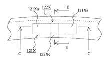
- FIG. 26 is a partially enlarged view of a side view of the seal ring according to the second embodiment of the present invention, and is an enlarged view showing the vicinity where the first groove and the second groove are provided.
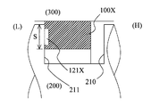
- FIG. 27 is a schematic cross-sectional view of a seal ring according to Embodiment 2 of the present invention, and is a cross-sectional view along AA in FIG. 28 and 29 are schematic cross-sectional views showing a state in use of the seal ring according to Embodiment 2 of the present invention.
- FIG. 28 shows a no-load state
- FIG. 29 shows a state where a differential pressure is generated.
- the seal ring in FIGS. 28 and 29 corresponds to the BB cross-sectional view in FIG.
- the seal ring 100X according to the present embodiment is mounted in an annular groove 210 provided on the outer periphery of the shaft 200, and rotates relative to the shaft 200 and the housing 300 (the inner periphery of the shaft hole through which the shaft 200 in the housing 300 is inserted.
- the annular gap between the first and second surfaces is sealed.
- the seal ring 100X maintains the fluid pressure in the region to be sealed configured so that the fluid pressure (hydraulic pressure in the present embodiment) changes.
- the fluid pressure in the region on the right side of the seal ring 100X in FIGS. 28 and 29 is configured to change.
- the seal ring 100X plays a role of maintaining the fluid pressure in the region to be sealed on the right side in the drawing via the seal ring 100X.
- the fluid pressure in the sealing target region is low and no load is applied.
- the fluid pressure in the sealing target region increases.
- FIG. 29 shows a state in which the fluid pressure on the right side in the drawing is higher than the fluid pressure on the left side.
- the right side in FIG. 29 is referred to as a high pressure side (H)
- the left side is referred to as a low pressure side (L).
- the seal ring 100X is made of a resin material such as polyether ether ketone (PEEK), polyphenylene sulfide (PPS), polytetrafluoroethylene (PTFE).
- PEEK polyether ether ketone
- PPS polyphenylene sulfide
- PTFE polytetrafluoroethylene
- the circumferential length of the outer circumferential surface of the seal ring 100X is shorter than the circumferential length of the inner circumferential surface of the shaft hole of the housing 300, and is configured so as not to have a tightening margin. Therefore, in the state where the fluid pressure is not acting, the outer peripheral surface of the seal ring 100X can be separated from the inner peripheral surface of the shaft hole of the housing 300 (see FIG. 28).
- the seal ring 100X is provided with an abutment portion 110X at one place in the circumferential direction.
- a first groove 121X and a second groove 122X are provided on the sliding surface side of the seal ring 100X.
- the seal ring 100X according to the present embodiment has a configuration in which the above-described joint portion 110X, the plurality of first grooves 121X, and the plurality of second grooves 122X are formed on an annular member having a rectangular cross section.
- this is merely an explanation of the shape, and it is always necessary to perform processing for forming the joint portion 110X, the plurality of first grooves 121X, and the plurality of second grooves 122X using an annular member having a rectangular cross section as a material.
- the configuration of the joint portion 110X according to the present embodiment will be described with reference to FIGS.
- the joint portion 110X according to the present embodiment employs a special step cut that is cut in a step shape when viewed from either the outer peripheral surface side or both side wall surfaces.
- the first fitting convex portion 111X and the first fitting concave portion 114X are provided on the outer peripheral surface side on one side via the cutting portion, and the outer peripheral surface side on the other side is provided.
- a second fitting recess 113X into which the first fitting projection 111X is fitted and a second fitting projection 112X to be fitted into the first fitting recess 114X are provided.
- the end surface 115X on the inner peripheral surface side on one side and the end surface 116X on the inner peripheral side on the other side are opposed to each other through the cutting portion. Since the special step cut is a known technique, a detailed description thereof will be omitted, but it has a characteristic of maintaining a stable sealing performance even if the circumference of the seal ring 100X changes due to thermal expansion and contraction.
- the “cutting portion” includes not only the case of being cut by cutting, but also the case of being obtained by molding.
- a plurality of first grooves 121X and second grooves 122X are provided at equal intervals over the entire circumference except for the vicinity of the joint portion 110X in the side surface on the sliding surface side of the seal ring 100 (see FIG. 21).
- the plurality of first grooves 121 ⁇ / b> X are provided to generate dynamic pressure when the seal ring 100 ⁇ / b> X slides with respect to the low-pressure side (L) side wall surface 211 in the annular groove 210 provided in the shaft 200. .
- the first groove 121X is configured to extend in the circumferential direction.
- the second groove 122X is provided so as to extend from the inner peripheral surface of the seal ring 100X to a position entering the center position in the circumferential direction of the first groove 121X.
- the second groove 122X guides the fluid to be sealed into the first groove 121X and plays a role of discharging foreign matter to the inner peripheral surface side of the seal ring 100X.
- the first groove 121X is configured such that the groove bottom is shallower at the end in the circumferential direction than the center in the circumferential direction on both sides in the circumferential direction across the portion where the second groove 122X has entered.
- a pair of dynamic pressure generating grooves 121Xa is provided (see FIGS. 26 and 27).
- the groove bottom of the dynamic pressure generating groove 121Xa is constituted by a flat inclined surface.
- the dynamic pressure generating groove 121Xa is not limited to the example shown in the drawings, and various known pressures may be used as long as the dynamic pressure generating groove 121Xa has a function of generating a dynamic pressure when the sealing target fluid is discharged from the groove to the sliding portion. Technology can be adopted.
- the first groove 121X is provided at a position where the seal ring 100X fits in the sliding area S where the seal ring 100X slides with respect to the low-pressure side (L) side wall surface 211 (see FIG. 29). Therefore, leakage of the sealing target fluid from the first groove 121X to the low pressure side (L) is suppressed.
- the groove bottom of the second groove 122X is deeper than the groove bottom of the dynamic pressure generating groove 121Xa. Accordingly, the second groove 122 exhibits a function of guiding the fluid to be sealed into the first groove 121 and discharging foreign matter that has entered the sliding portion to the inner peripheral surface side of the seal ring 100X.
- FIG. 29 shows a state where the engine is started and a differential pressure is generated via the seal ring 100X (a state in which the pressure on the right side in the drawing is higher than the pressure on the left side).
- the seal ring 100X is in close contact with the side wall surface 211 on the low pressure side (L) of the annular groove 210 and the inner peripheral surface of the shaft hole of the housing 300.
- the annular gap between the relatively rotating shaft 200 and the housing 300 is sealed, and the fluid pressure in the region to be sealed (the region on the high pressure side (H)) configured to change the fluid pressure. Can be held.
- the shaft 200 and the housing 300 rotate relatively, they slide between the low pressure side (L) side wall surface 211 of the annular groove 210 and the seal ring 100X.
- dynamic pressure is generated when the fluid to be sealed flows out from the dynamic pressure generating groove 121a provided on the sliding surface side of the seal ring 100X to the sliding portion.
- the seal ring 100X rotates in the clockwise direction in FIG.
- the fluid to be sealed flows from the counterclockwise end of the dynamic pressure generating groove 121Xa to the sliding portion. leak.
- the seal ring 100X rotates in the counterclockwise direction in FIG. 21 with respect to the annular groove 210, the fluid to be sealed flows from the end of the dynamic pressure generating groove 121a on the sliding side to the sliding portion. leak.
- the dynamic pressure is generated by the fluid to be sealed flowing out from the dynamic pressure generating groove 121Xa to the sliding portion.
- the groove bottom of the dynamic pressure generating groove 121Xa is configured so that the end portion in the circumferential direction is shallower than the center in the circumferential direction. Can be generated.
- the dynamic pressure generating grooves are provided on both sides in the circumferential direction across the portion into which the second groove 122X has entered, the dynamic pressure generating function is provided regardless of the rotational direction of the seal ring 100X with respect to the shaft 200. It can be demonstrated.
- the first groove 121X is provided at a position within the sliding region S that slides with respect to the side wall surface 211, the leakage amount of the fluid to be sealed from the first groove 121X can be suppressed.
- a second groove 122X having a deeper bottom than the groove bottom of the dynamic pressure generating groove 121Xa is provided, and foreign matter that has entered the sliding portion can be discharged to the inner peripheral surface side by the second groove 122X. . Accordingly, it is possible to prevent the dynamic pressure generating function of the dynamic pressure generating groove 121Xa from being damaged by the foreign matter. That is, it is possible to prevent foreign matter from being caught between the dynamic pressure generating groove 121Xa and the side wall surface 211. Thereby, it can suppress that a dynamic pressure effect will be reduced, and can suppress that wear is accelerated
- FIG. 30 is a partial enlarged view of a side view of the seal ring according to the eleventh embodiment of the present invention, and is an enlarged view of the vicinity where the first groove 121X and the second groove 122X are provided.
- FIG. 31 is a schematic sectional view of a seal ring according to an eleventh embodiment of the present invention, which is a CC sectional view in FIG. 32 is a schematic cross-sectional view of a seal ring according to Example 11 of the present invention, which is a DD cross-sectional view in FIG.
- FIG. 33 is a schematic cross-sectional view of a seal ring according to Example 11 of the present invention, and is an EE cross-sectional view in FIG.
- the first groove 121X extending in the circumferential direction, and the center position in the circumferential direction of the first groove 121X from the inner peripheral surface of the seal ring 100X.
- a second groove 122X extending to the position of entering.
- the pair of dynamic pressure generating grooves 121Xa in the first groove 121X is configured to have a constant radial width. Then, between the pair of dynamic pressure generating grooves 121Xa and outside the second groove 122X in the radial direction, a sealing target from one dynamic pressure generating groove 121Xa to the other dynamic pressure generating groove 121Xa.
- a barrier portion 123X that prevents the flow of fluid is provided. The surface of the barrier portion 123X is flush with the side surface of the seal ring 100X (excluding the portion where the first groove 121X and the second groove 122X are provided).
- the effects described in the second embodiment can be obtained by the first groove 121X and the second groove 122X according to the present example configured as described above.
- the fluid flowing from one dynamic pressure generating groove 121Xa to the other dynamic pressure generating groove 121Xa is directed radially inward in the second groove 122X by the barrier portion 123X. It becomes easy to flow. That is, when the seal ring 100X rotates counterclockwise in FIG. 30 with respect to the annular groove 210, the fluid flowing from the dynamic pressure generating groove 121Xa on the left side to the right dynamic pressure generating groove 121Xa in the figure.
- the second groove 122X is obstructed by the barrier portion 123X, so that the second groove 122X can easily flow inward in the radial direction.
- the barrier portion 123X prevents the second groove 122X from flowing inward in the radial direction. Thereby, the foreign matter that has entered the sliding surface is positively discharged to the inner peripheral surface side of the seal ring 100.
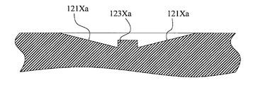
- FIG. 34 is a partially enlarged side view of the seal ring according to the twelfth embodiment of the present invention, and is an enlarged view of the vicinity where the first groove 121X and the second groove 122X are provided.
- FIG. 35 is a schematic cross-sectional view of a seal ring according to Embodiment 12 of the present invention, which is a cross-sectional view taken along CC in FIG. 36 is a schematic cross-sectional view of a seal ring according to Embodiment 12 of the present invention, and is a DD cross-sectional view in FIG.
- FIG. 37 is a schematic cross-sectional view of a seal ring according to Embodiment 12 of the present invention, and is a cross-sectional view taken along the line EE in FIG.
- the first groove 121X extending in the circumferential direction, and the circumference in the first groove 121X from the inner peripheral surface of the seal ring 100X.
- a second groove 122 ⁇ / b> X extending to a position entering the central position in the direction is provided.
- the pair of dynamic pressure generating grooves 121Xa in the first groove 121X is configured to have a constant radial width.
- a barrier portion 123Xa that prevents the flow of fluid is provided.
- the barrier portion 123Xa in the present embodiment is configured to be lower in height than the barrier portion 123X in the eleventh embodiment. That is, the surface of the barrier portion 123Xa in the present embodiment is positioned slightly inside the side surface (excluding the portion where the first groove 121X and the second groove 122X are provided) in the seal ring 100X.
- FIG. 38 is a partially enlarged side view of the seal ring according to the thirteenth embodiment of the present invention, and is an enlarged view of the vicinity where the first groove 121X and the second groove 122X are provided.
- the first groove 121X extending in the circumferential direction, and the circumference in the first groove 121X from the inner peripheral surface of the seal ring 100X.
- a second groove 122 ⁇ / b> X extending to a position entering the central position in the direction is provided.
- the pair of dynamic pressure generating grooves 121Xa in the first groove 121X is configured to have a constant radial width.
- a barrier portion 123Xb that prevents the flow of fluid is provided.
- the inner peripheral surface side of the barrier portion 123Xb is configured by a curved surface.
- the same function and effect as in the case of the eleventh embodiment can be obtained.
- the inner peripheral surface side of the barrier portion 123Xb is configured by a curved surface, the flow of fluid from the dynamic pressure generating groove 121Xa to the second groove 122X can be made smooth.
- FIG. 39 is a partial enlarged view of a side view of the seal ring according to the fourteenth embodiment of the present invention, and is an enlarged view of the vicinity where the first groove 121X and the second groove 122X are provided.
- 40 is a schematic cross-sectional view of a seal ring according to Embodiment 14 of the present invention, which is a CC cross-sectional view in FIG. 41 is a schematic cross-sectional view of a seal ring according to Embodiment 14 of the present invention, which is a DD cross-sectional view in FIG. 42 is a schematic cross-sectional view of a seal ring according to Embodiment 14 of the present invention, and is an EE cross-sectional view in FIG.
- the first groove 121X extending in the circumferential direction, and the center position in the circumferential direction of the first groove 121X from the inner peripheral surface of the seal ring 100X.
- a second groove 122X extending to the position of entering.
- the pair of dynamic pressure generating grooves 121Xa in the first groove 121X is configured to have a constant radial width.
- channel 122X which concerns on a present Example is comprised by the step-like level
- the groove bottom of the second groove 122X is constituted by a two-step step surface composed of a radially inner groove bottom surface 122Xa and a radially outer groove bottom surface 122Xb.
- the groove bottom surface 122a on the radially inner side is configured to have a deeper groove bottom than the groove bottom surface 122Xb on the radially outer side.
- the case where the groove bottom of the second groove 122X is configured by two step surfaces has been described, but it may be configured by three or more step surfaces.
- the groove bottom of the second groove 122X is formed by a stepped step surface having a groove depth that increases from the radially outer side to the inner side.
- the entered foreign matter can be positively discharged to the inner peripheral surface side of the seal ring 100X.
- FIG. 43 is a partial enlarged view of a side view of the seal ring according to the fifteenth embodiment of the present invention, and is an enlarged view of the vicinity where the first groove 121X and the second groove 122X are provided.
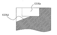
- 44 is a schematic cross-sectional view of a seal ring according to Embodiment 15 of the present invention, which is a CC cross-sectional view in FIG. 45 is a schematic cross-sectional view of a seal ring according to Embodiment 15 of the present invention, and is an EE cross-sectional view in FIG.
- FIG. 46 is a schematic sectional view of a seal ring according to a modification of the fifteenth embodiment of the present invention.
- the first groove 121X extending in the circumferential direction, and the center position in the circumferential direction of the first groove 121X from the inner peripheral surface of the seal ring 100X.
- a second groove 122X extending to the position of entering.
- the pair of dynamic pressure generating grooves 121Xa in the first groove 121X is configured to have a constant radial width.
- channel 122X which concerns on a present Example is comprised by the inclined surface 122Xc from which a groove depth becomes deep toward inner side from the outer side of radial direction.
- the effects described in the second embodiment can be obtained by the first groove 121X and the second groove 122X according to the present example configured as described above.
- the groove bottom of the second groove 122X is configured by the inclined surface 122Xc having a groove depth that increases from the outer side to the inner side in the radial direction, and thus enters the second groove 122X. Foreign matter can be positively discharged to the inner peripheral surface side of the seal ring 100X.
- the case where the entire groove bottom of the second groove 122X is configured as an inclined surface has been shown, but for example, as in the modification shown in FIG. 46, among the groove bottom surfaces of the second groove 122X,
- the radially outer side may be constituted by a plane, and the radially inner side may be constituted by an inclined surface 122Xd in which the groove depth increases from the radially outer side toward the inner side. Even in this case, the same effect can be obtained.
- the groove bottom of the dynamic pressure generating groove 121Xa is constituted by a flat inclined surface
- the curved surface shape which swells to the inner peripheral surface side or the outer peripheral surface side. You may comprise by the inclined surface.
- the first groove 121X and the second groove 122X may be provided only on one side of the seal ring 100X, or may be provided on both sides. In short, the surface on which the first groove 121X and the second groove 122X are provided may be a sliding surface.
Landscapes
- Engineering & Computer Science (AREA)
- General Engineering & Computer Science (AREA)
- Mechanical Engineering (AREA)
- Sealing Devices (AREA)
- Mechanical Sealing (AREA)
Abstract
Priority Applications (5)
| Application Number | Priority Date | Filing Date | Title |
|---|---|---|---|
| US15/557,955 US10408349B2 (en) | 2015-03-16 | 2016-03-11 | Seal ring |
| JP2017506515A JP6245406B2 (ja) | 2015-03-16 | 2016-03-11 | シールリング |
| KR1020177025728A KR101972253B1 (ko) | 2015-03-16 | 2016-03-11 | 실 링 |
| CN201680014654.7A CN107407418B (zh) | 2015-03-16 | 2016-03-11 | 密封圈 |
| EP16764878.1A EP3273117B1 (fr) | 2015-03-16 | 2016-03-11 | Bague d'étanchéité |
Applications Claiming Priority (4)
| Application Number | Priority Date | Filing Date | Title |
|---|---|---|---|
| JP2015052587 | 2015-03-16 | ||
| JP2015-052676 | 2015-03-16 | ||
| JP2015-052587 | 2015-03-16 | ||
| JP2015052676 | 2015-03-16 |
Publications (1)
| Publication Number | Publication Date |
|---|---|
| WO2016148048A1 true WO2016148048A1 (fr) | 2016-09-22 |
Family
ID=56918919
Family Applications (1)
| Application Number | Title | Priority Date | Filing Date |
|---|---|---|---|
| PCT/JP2016/057718 Ceased WO2016148048A1 (fr) | 2015-03-16 | 2016-03-11 | Bague d'étanchéité |
Country Status (6)
| Country | Link |
|---|---|
| US (1) | US10408349B2 (fr) |
| EP (1) | EP3273117B1 (fr) |
| JP (1) | JP6245406B2 (fr) |
| KR (1) | KR101972253B1 (fr) |
| CN (1) | CN107407418B (fr) |
| WO (1) | WO2016148048A1 (fr) |
Cited By (6)
| Publication number | Priority date | Publication date | Assignee | Title |
|---|---|---|---|---|
| WO2019059341A1 (fr) * | 2017-09-21 | 2019-03-28 | Nok株式会社 | Bague d'étanchéité |
| JP2020106134A (ja) * | 2018-12-28 | 2020-07-09 | Ntn株式会社 | シールリング |
| JPWO2021230081A1 (fr) * | 2020-05-11 | 2021-11-18 | ||
| US11525512B2 (en) * | 2018-05-17 | 2022-12-13 | Eagle Industry Co., Ltd. | Seal ring |
| WO2025023217A1 (fr) * | 2023-07-27 | 2025-01-30 | イーグル工業株式会社 | Bague d'étanchéité |
| WO2025023214A1 (fr) * | 2023-07-27 | 2025-01-30 | イーグル工業株式会社 | Bague d'étanchéité |
Families Citing this family (18)
| Publication number | Priority date | Publication date | Assignee | Title |
|---|---|---|---|---|
| JP6756053B2 (ja) * | 2018-03-20 | 2020-09-16 | Nok株式会社 | 密封装置 |
| US11644100B2 (en) | 2018-05-17 | 2023-05-09 | Eagle Industry Co., Ltd. | Seal ring |
| CN112105850A (zh) * | 2018-05-17 | 2020-12-18 | 伊格尔工业股份有限公司 | 密封环 |
| EP3816490B1 (fr) * | 2018-05-17 | 2024-11-06 | Eagle Industry Co., Ltd. | Bague d'étanchéité |
| EP3842673B1 (fr) | 2018-08-24 | 2026-04-22 | Eagle Industry Co., Ltd. | Élément coulissant |
| EP3862600B1 (fr) | 2018-10-01 | 2025-05-21 | Eagle Industry Co., Ltd. | Élément coulissant |
| CN112789434B (zh) | 2018-10-24 | 2023-09-29 | 伊格尔工业股份有限公司 | 滑动部件 |
| EP3889474A4 (fr) | 2018-11-30 | 2022-08-10 | Eagle Industry Co., Ltd. | Élément coulissant |
| KR102541901B1 (ko) | 2018-12-21 | 2023-06-13 | 이구루코교 가부시기가이샤 | 슬라이딩 부품 |
| KR102610647B1 (ko) | 2019-02-04 | 2023-12-07 | 이구루코교 가부시기가이샤 | 슬라이딩 부품 |
| CN117432709A (zh) | 2019-02-14 | 2024-01-23 | 伊格尔工业股份有限公司 | 滑动部件 |
| JP7374573B2 (ja) | 2019-02-21 | 2023-11-07 | イーグル工業株式会社 | 摺動部品 |
| JP7399966B2 (ja) * | 2019-07-26 | 2023-12-18 | イーグル工業株式会社 | 摺動部品 |
| WO2021117335A1 (fr) * | 2019-12-09 | 2021-06-17 | Nok株式会社 | Dispositif d'étanchéité |
| CN115298462B (zh) | 2020-03-31 | 2025-04-11 | 伊格尔工业股份有限公司 | 滑动部件 |
| EP4306826A4 (fr) | 2021-03-12 | 2025-03-26 | Eagle Industry Co., Ltd. | Élément coulissant |
| US12404936B2 (en) | 2021-09-28 | 2025-09-02 | Eagle Indusry Co., Ltd. | Sliding component |
| KR102921449B1 (ko) * | 2023-11-30 | 2026-02-02 | 평화오일씰공업주식회사 | 오일 씰 링 |
Citations (4)
| Publication number | Priority date | Publication date | Assignee | Title |
|---|---|---|---|---|
| JPH08121603A (ja) * | 1994-10-25 | 1996-05-17 | Nok Corp | シ−ルリング |
| JP2002276815A (ja) * | 2001-03-16 | 2002-09-25 | Nok Corp | シールリング |
| WO2011105513A1 (fr) * | 2010-02-26 | 2011-09-01 | Nok株式会社 | Bague d'étanchéité |
| JP2015028382A (ja) * | 2013-07-03 | 2015-02-12 | Ntn株式会社 | シールリング |
Family Cites Families (21)
| Publication number | Priority date | Publication date | Assignee | Title |
|---|---|---|---|---|
| US4082296A (en) * | 1976-05-26 | 1978-04-04 | Stein Philip C | Seal for sealing between a rotating member and a housing |
| US5169159A (en) * | 1991-09-30 | 1992-12-08 | General Electric Company | Effective sealing device for engine flowpath |
| US5171027A (en) * | 1992-01-31 | 1992-12-15 | Parker-Hannifin Corporation | High temperature and pressure fluid seal |
| US5328178A (en) * | 1992-10-14 | 1994-07-12 | General Motors Corporation | Brake master cylinder seal |
| JPH09210211A (ja) * | 1996-02-01 | 1997-08-12 | Riken Corp | シールリング |
| CN1087061C (zh) * | 1998-08-13 | 2002-07-03 | 王玉明 | 可双向旋转的双列双叶螺旋槽端面密封 |
| CN1167890C (zh) * | 2001-01-18 | 2004-09-22 | 王玉明 | 可双向旋转的螺旋槽端面密封装置 |
| JP2006009897A (ja) * | 2004-06-24 | 2006-01-12 | Nok Corp | シールリング |
| JP2007078041A (ja) * | 2005-09-13 | 2007-03-29 | Ntn Corp | 樹脂製シールリング |
| JP2011105513A (ja) * | 2009-11-13 | 2011-06-02 | Terabondo:Kk | 重荷物昇降補助装置。 |
| EP2549155B1 (fr) * | 2010-03-15 | 2016-08-10 | Eagle Industry Co., Ltd. | Elément coulissant |
| KR101463366B1 (ko) * | 2011-12-23 | 2014-11-19 | 가부시끼가이샤 리켄 | 시일 링 |
| CN102518809B (zh) * | 2011-12-29 | 2015-04-22 | 江苏大学 | 一种防固体颗粒吸入型流体动压机械密封环 |
| CN102619742B (zh) | 2012-03-07 | 2016-04-20 | 大连华阳密封股份有限公司 | 用于双向旋转内压式泵用干气密封装置 |
| CN102588605B (zh) * | 2012-03-22 | 2014-08-13 | 成都一通密封有限公司 | 双向干气密封摩擦副 |
| JP2014055645A (ja) * | 2012-09-13 | 2014-03-27 | Nok Corp | シールリング |
| CN103104707B (zh) * | 2013-01-30 | 2015-10-28 | 浙江工业大学 | 似蘑菇型槽双向旋转流体动压型机械密封结构 |
| WO2015045974A1 (fr) * | 2013-09-27 | 2015-04-02 | 株式会社リケン | Bague d'étanchéité |
| CN103453147B (zh) * | 2013-09-30 | 2016-04-13 | 四川日机密封件股份有限公司 | 具有双旋向流体动压槽的非接触式机械密封环 |
| US10865883B2 (en) | 2014-01-24 | 2020-12-15 | Nok Corporation | Sealing ring |
| JP6424949B2 (ja) * | 2015-03-16 | 2018-11-21 | Nok株式会社 | シールリング |
-
2016
- 2016-03-11 EP EP16764878.1A patent/EP3273117B1/fr active Active
- 2016-03-11 WO PCT/JP2016/057718 patent/WO2016148048A1/fr not_active Ceased
- 2016-03-11 JP JP2017506515A patent/JP6245406B2/ja active Active
- 2016-03-11 CN CN201680014654.7A patent/CN107407418B/zh active Active
- 2016-03-11 US US15/557,955 patent/US10408349B2/en active Active
- 2016-03-11 KR KR1020177025728A patent/KR101972253B1/ko active Active
Patent Citations (4)
| Publication number | Priority date | Publication date | Assignee | Title |
|---|---|---|---|---|
| JPH08121603A (ja) * | 1994-10-25 | 1996-05-17 | Nok Corp | シ−ルリング |
| JP2002276815A (ja) * | 2001-03-16 | 2002-09-25 | Nok Corp | シールリング |
| WO2011105513A1 (fr) * | 2010-02-26 | 2011-09-01 | Nok株式会社 | Bague d'étanchéité |
| JP2015028382A (ja) * | 2013-07-03 | 2015-02-12 | Ntn株式会社 | シールリング |
Cited By (15)
| Publication number | Priority date | Publication date | Assignee | Title |
|---|---|---|---|---|
| KR20200044940A (ko) * | 2017-09-21 | 2020-04-29 | 엔오케이 가부시키가이샤 | 밀봉 링 |
| CN111108312A (zh) * | 2017-09-21 | 2020-05-05 | Nok株式会社 | 密封环 |
| WO2019059341A1 (fr) * | 2017-09-21 | 2019-03-28 | Nok株式会社 | Bague d'étanchéité |
| JPWO2019059341A1 (ja) * | 2017-09-21 | 2020-10-15 | Nok株式会社 | シールリング |
| DE112018004245B4 (de) * | 2017-09-21 | 2025-05-22 | Nok Corporation | Dichtring |
| KR102387229B1 (ko) | 2017-09-21 | 2022-04-15 | 엔오케이 가부시키가이샤 | 밀봉 링 |
| US11320051B2 (en) | 2017-09-21 | 2022-05-03 | Nok Corporation | Seal ring |
| JP7164533B2 (ja) | 2017-09-21 | 2022-11-01 | Nok株式会社 | シールリング |
| US11525512B2 (en) * | 2018-05-17 | 2022-12-13 | Eagle Industry Co., Ltd. | Seal ring |
| JP2020106134A (ja) * | 2018-12-28 | 2020-07-09 | Ntn株式会社 | シールリング |
| JP7166167B2 (ja) | 2018-12-28 | 2022-11-07 | Ntn株式会社 | シールリング |
| JP7543401B2 (ja) | 2020-05-11 | 2024-09-02 | イーグル工業株式会社 | 摺動部品 |
| JPWO2021230081A1 (fr) * | 2020-05-11 | 2021-11-18 | ||
| WO2025023217A1 (fr) * | 2023-07-27 | 2025-01-30 | イーグル工業株式会社 | Bague d'étanchéité |
| WO2025023214A1 (fr) * | 2023-07-27 | 2025-01-30 | イーグル工業株式会社 | Bague d'étanchéité |
Also Published As
| Publication number | Publication date |
|---|---|
| US10408349B2 (en) | 2019-09-10 |
| JP6245406B2 (ja) | 2017-12-13 |
| EP3273117A4 (fr) | 2018-11-21 |
| EP3273117A1 (fr) | 2018-01-24 |
| CN107407418B (zh) | 2019-09-06 |
| KR20170117515A (ko) | 2017-10-23 |
| KR101972253B1 (ko) | 2019-04-24 |
| EP3273117B1 (fr) | 2019-10-23 |
| JPWO2016148048A1 (ja) | 2017-11-16 |
| CN107407418A (zh) | 2017-11-28 |
| US20180058584A1 (en) | 2018-03-01 |
Similar Documents
| Publication | Publication Date | Title |
|---|---|---|
| JP6245406B2 (ja) | シールリング | |
| JP6491374B2 (ja) | シールリング | |
| JP6424949B2 (ja) | シールリング | |
| JP6615833B2 (ja) | シールリング | |
| JP6314689B2 (ja) | 密封装置 | |
| KR102362482B1 (ko) | 실 링 | |
| JP2015158215A (ja) | シールリング | |
| WO2019155945A1 (fr) | Bague d'étanchéité | |
| JP6597840B2 (ja) | 軸及び密封構造 | |
| KR102685516B1 (ko) | 밀봉장치 | |
| JP6170271B2 (ja) | シールリング | |
| WO2015020075A1 (fr) | Bague d'étanchéité | |
| JP2017101736A (ja) | シールリング |
Legal Events
| Date | Code | Title | Description |
|---|---|---|---|
| 121 | Ep: the epo has been informed by wipo that ep was designated in this application |
Ref document number: 16764878 Country of ref document: EP Kind code of ref document: A1 |
|
| ENP | Entry into the national phase |
Ref document number: 2017506515 Country of ref document: JP Kind code of ref document: A |
|
| ENP | Entry into the national phase |
Ref document number: 20177025728 Country of ref document: KR Kind code of ref document: A |
|
| WWE | Wipo information: entry into national phase |
Ref document number: 15557955 Country of ref document: US |
|
| NENP | Non-entry into the national phase |
Ref country code: DE |
|
| REEP | Request for entry into the european phase |
Ref document number: 2016764878 Country of ref document: EP |