WO2016148208A1 - Feuille adhésive pour dispositif d'affichage d'image, corps stratifié adhésif pour dispositif d'affichage d'image, et dispositif d'affichage d'image - Google Patents
Feuille adhésive pour dispositif d'affichage d'image, corps stratifié adhésif pour dispositif d'affichage d'image, et dispositif d'affichage d'image Download PDFInfo
- Publication number
- WO2016148208A1 WO2016148208A1 PCT/JP2016/058399 JP2016058399W WO2016148208A1 WO 2016148208 A1 WO2016148208 A1 WO 2016148208A1 JP 2016058399 W JP2016058399 W JP 2016058399W WO 2016148208 A1 WO2016148208 A1 WO 2016148208A1
- Authority
- WO
- WIPO (PCT)
- Prior art keywords
- image display
- display device
- meth
- acrylate
- pressure
- Prior art date
- Legal status (The legal status is an assumption and is not a legal conclusion. Google has not performed a legal analysis and makes no representation as to the accuracy of the status listed.)
- Ceased
Links
Images





Classifications
-
- C—CHEMISTRY; METALLURGY
- C09—DYES; PAINTS; POLISHES; NATURAL RESINS; ADHESIVES; COMPOSITIONS NOT OTHERWISE PROVIDED FOR; APPLICATIONS OF MATERIALS NOT OTHERWISE PROVIDED FOR
- C09J—ADHESIVES; NON-MECHANICAL ASPECTS OF ADHESIVE PROCESSES IN GENERAL; ADHESIVE PROCESSES NOT PROVIDED FOR ELSEWHERE; USE OF MATERIALS AS ADHESIVES
- C09J7/00—Adhesives in the form of films or foils
- C09J7/10—Adhesives in the form of films or foils without carriers
-
- C—CHEMISTRY; METALLURGY
- C09—DYES; PAINTS; POLISHES; NATURAL RESINS; ADHESIVES; COMPOSITIONS NOT OTHERWISE PROVIDED FOR; APPLICATIONS OF MATERIALS NOT OTHERWISE PROVIDED FOR
- C09J—ADHESIVES; NON-MECHANICAL ASPECTS OF ADHESIVE PROCESSES IN GENERAL; ADHESIVE PROCESSES NOT PROVIDED FOR ELSEWHERE; USE OF MATERIALS AS ADHESIVES
- C09J11/00—Features of adhesives not provided for in group C09J9/00, e.g. additives
- C09J11/02—Non-macromolecular additives
- C09J11/06—Non-macromolecular additives organic
-
- C—CHEMISTRY; METALLURGY
- C09—DYES; PAINTS; POLISHES; NATURAL RESINS; ADHESIVES; COMPOSITIONS NOT OTHERWISE PROVIDED FOR; APPLICATIONS OF MATERIALS NOT OTHERWISE PROVIDED FOR
- C09J—ADHESIVES; NON-MECHANICAL ASPECTS OF ADHESIVE PROCESSES IN GENERAL; ADHESIVE PROCESSES NOT PROVIDED FOR ELSEWHERE; USE OF MATERIALS AS ADHESIVES
- C09J133/00—Adhesives based on homopolymers or copolymers of compounds having one or more unsaturated aliphatic radicals, each having only one carbon-to-carbon double bond, and at least one being terminated by only one carboxyl radical, or of salts, anhydrides, esters, amides, imides, or nitriles thereof; Adhesives based on derivatives of such polymers
- C09J133/04—Homopolymers or copolymers of esters
- C09J133/14—Homopolymers or copolymers of esters of esters containing halogen, nitrogen, sulfur or oxygen atoms in addition to the carboxy oxygen
-
- G—PHYSICS
- G02—OPTICS
- G02F—OPTICAL DEVICES OR ARRANGEMENTS FOR THE CONTROL OF LIGHT BY MODIFICATION OF THE OPTICAL PROPERTIES OF THE MEDIA OF THE ELEMENTS INVOLVED THEREIN; NON-LINEAR OPTICS; FREQUENCY-CHANGING OF LIGHT; OPTICAL LOGIC ELEMENTS; OPTICAL ANALOGUE/DIGITAL CONVERTERS
- G02F1/00—Devices or arrangements for the control of the intensity, colour, phase, polarisation or direction of light arriving from an independent light source, e.g. switching, gating or modulating; Non-linear optics
- G02F1/01—Devices or arrangements for the control of the intensity, colour, phase, polarisation or direction of light arriving from an independent light source, e.g. switching, gating or modulating; Non-linear optics for the control of the intensity, phase, polarisation or colour
- G02F1/13—Devices or arrangements for the control of the intensity, colour, phase, polarisation or direction of light arriving from an independent light source, e.g. switching, gating or modulating; Non-linear optics for the control of the intensity, phase, polarisation or colour based on liquid crystals, e.g. single liquid crystal display cells
- G02F1/133—Constructional arrangements; Operation of liquid crystal cells; Circuit arrangements
- G02F1/1333—Constructional arrangements; Manufacturing methods
-
- G—PHYSICS
- G06—COMPUTING OR CALCULATING; COUNTING
- G06F—ELECTRIC DIGITAL DATA PROCESSING
- G06F3/00—Input arrangements for transferring data to be processed into a form capable of being handled by the computer; Output arrangements for transferring data from processing unit to output unit, e.g. interface arrangements
- G06F3/01—Input arrangements or combined input and output arrangements for interaction between user and computer
- G06F3/03—Arrangements for converting the position or the displacement of a member into a coded form
- G06F3/041—Digitisers, e.g. for touch screens or touch pads, characterised by the transducing means
-
- G—PHYSICS
- G09—EDUCATION; CRYPTOGRAPHY; DISPLAY; ADVERTISING; SEALS
- G09F—DISPLAYING; ADVERTISING; SIGNS; LABELS OR NAME-PLATES; SEALS
- G09F9/00—Indicating arrangements for variable information in which the information is built-up on a support by selection or combination of individual elements
Definitions
- the present invention relates to an adhesive sheet for an image display device, an adhesive laminate for an image display device, and an image display device.
- FIG. 10 shows a schematic diagram of a liquid crystal display device as an example of an image display device.
- a liquid crystal display device with a built-in touch panel is composed of a transparent protective plate D1, a touch panel D2, a polarizing plate D3, and a liquid crystal display cell D4.
- the liquid crystal display device is prevented from cracking, stress and impact are alleviated, and visibility is improved.
- an adhesive layer (transparent resin layer) D5 may be provided between the transparent protective plate and the touch panel
- an adhesive layer (transparent resin layer) D6 may be provided between the touch panel and the polarizing plate.
- the material of the transparent protective plate is mainly made of glass, but it is inexpensive and has excellent impact resistance (such as polycarbonate or polymethyl methacrylate (hereinafter abbreviated as PMMA), polycarbonate / PMMA multilayer product). Replacement is being considered.
- a frame-shaped decorative portion D7 is provided by printing or the like (19 (frame pattern) in FIG. 1 of Patent Document 1).
- a film-like pressure-sensitive adhesive may be used as the pressure-sensitive adhesive that bonds the transparent protective plate.
- An excellent step embedding property is required for an adhesive.
- various film-like pressure-sensitive adhesives for improving such step embedding have been studied (for example, Patent Document 2 and Patent Document 3).
- the film-like pressure sensitive adhesive D9 as described in Patent Document 2 and Patent Document 3 has insufficient step embedding properties when the height of the stepped portion D7 is increased.
- the thickness of the film-like adhesive has been reduced, and if the thickness of the film-like adhesive is thin and the stepped portion is high, the step embedding property of the film-like adhesive becomes more difficult. There is a tendency.
- the present invention has been made in view of the above circumstances, and is excellent in embedding in a step formed on an adherend, and is excellent in workability in a process of processing and bonding into a shape suitable for an image display device. It aims at providing the adhesive sheet for image display apparatuses. Another object of the present invention is to provide an adhesive laminate for an image display device and an image display device using the adhesive sheet for an image display device.
- the pressure-sensitive adhesive sheet for an image display device of the present invention has a tan ⁇ at 40 to 70 ° C. of 0.35 or more, a tensile secant modulus in a tensile stress-strain curve of 0.6 to 1.4 MPa, and a tensile breaking elongation. Is 150 mm or less.
- the pressure-sensitive adhesive sheet for an image display device includes 50 to 90 parts by mass of (a) an alkyl (meth) acrylate having an alkyl group having 1 to 18 carbon atoms, 10 to 30 parts by mass of (b) a (meth) acrylate having a hydroxyl group. And (c) a copolymer of a monomer mixture containing (c) an alicyclic substituent or a (meth) acrylate having a tertiary alkyl group.
- the pressure-sensitive adhesive sheet for an image display device further contains a crosslinking agent.
- the pressure-sensitive adhesive sheet for an image display device further contains an ultraviolet absorber.
- the haze value of the pressure-sensitive adhesive sheet for an image display device is preferably 1.5% or less.
- the present invention also provides a laminate for an image display device, comprising: the pressure-sensitive adhesive sheet for an image display device, and at least a pair of base materials laminated so as to sandwich the pressure-sensitive adhesive sheet for an image display device.
- the adhesive laminate can be easily stored and transported without damaging the adhesive layer.
- the present invention provides an image display unit, a transparent protective plate, an adhesive layer formed from the above-mentioned adhesive sheet for an image display device, which is interposed between the image display unit and the transparent protective plate, or a transparent resin layer that is a cured product thereof.
- An image display device is provided.
- the present invention is formed of the image display unit, the transparent protective plate, the touch panel, the image display unit and the transparent protective plate, or the adhesive sheet for an image display device interposed between the touch panel and the transparent protective plate.
- An image display device comprising: a pressure-sensitive adhesive layer or a transparent resin layer that is a cured product thereof.
- a pressure-sensitive adhesive sheet for an image display device that is excellent in embedding in a step formed on an adherend, and that is processed into a shape suitable for an image display device and has excellent workability in a process of bonding. can do.
- the adhesive laminated body for image displays which used the adhesive sheet for image displays, and an image display can be provided.
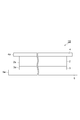
- FIG. 1 is a perspective view showing an embodiment of a laminate (three-layer product) for an image display device according to the present invention.
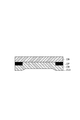
- FIG. 2 is a side cross-sectional view taken along line II-II in FIG. It is sectional drawing which shows one Embodiment of the image display apparatus of this invention. It is sectional drawing which shows one Embodiment of the image display apparatus of this invention. It is a perspective view which shows one Embodiment of the adhesion laminated body (4 layer goods) which concerns on this invention.
- FIG. 6 is a side sectional view taken along line VI-VI in FIG. 5. It is a schematic diagram which shows the sample measuring method using a wide area dynamic viscoelasticity measuring apparatus.
- the term “(meth) acrylate” means “acrylate” or “methacrylate” corresponding thereto.
- the term “(meth) acryl” means “acryl” or “methacryl” corresponding thereto, and the term “(meth) acryloyl” means “acryloyl” or corresponding “methacryloyl”.
- the pressure-sensitive adhesive sheet for an image display device and the pressure-sensitive adhesive laminate for an image display device are also simply referred to as a pressure-sensitive adhesive sheet and a pressure-sensitive adhesive laminate, respectively.
- the adhesive laminate 1A for an image display device includes an adhesive layer and a pair of base material layers laminated so as to sandwich the adhesive layer. It is preferable that the outer edge of the base material layer projects outward from the outer edge of the adhesive layer.
- the pressure-sensitive adhesive laminate 1 ⁇ / b> A includes a transparent film-like pressure-sensitive adhesive layer 2 and a heavy release separator 3 (one side) sandwiched between the pressure-sensitive adhesive layers 2. And a light release separator 4 (the other substrate). It is preferable that the outer edges of the heavy release separator 3 and the light release separator 4 protrude beyond the outer edge of the adhesive layer 2.
- This adhesive layer 2 is a transparent film disposed between a transparent protective plate and a touch panel or between a touch panel and a liquid crystal display unit in an image display device such as a touch panel display for a portable terminal.
- optically transparent substrates include glass, polycarbonate, polyester (for example, polyethylene terephthalate and polyethylene naphthalate), polyurethane, poly (meth) acrylate (for example, PMMA), polyvinyl alcohol, polyolefin (for example, polyethylene). , Polypropylene, and cellulose triacetate), and the like, are not particularly limited.
- the adhesive layer 2 corresponds to an adhesive sheet for an image display device described later. For this reason, in addition to adhesive force, the adhesion layer 2 has the effect which was more excellent about surface flatness.
- the pressure-sensitive adhesive layer 2 (pressure-sensitive adhesive sheet) according to this embodiment has a tan ⁇ at 40 to 70 ° C. of 0.35 or more, a tensile secant modulus in a tensile stress-strain curve of 0.6 to 1.4 MPa, and The tensile elongation at break is 150 mm or less. According to such an adhesive sheet, it is excellent in embedding in the level difference formed on the adherend, and is excellent in workability in the process of processing into a shape suitable for the image display device and bonding.
- the tan ⁇ at 40 to 70 ° C. of the adhesive layer 2 may be 0.35 to 2.0, 0.4 to 2.0, or 0.4 to 1.9.
- the tan ⁇ at 40 to 70 ° C. is 0.35 or more, the embedding property to the step and the surface flatness tend to be further improved.
- the tan ⁇ at 40 to 70 ° C. is 2 or less, the film formability tends to be good.
- the meaning of the lower limit means that the tan ⁇ value of the adhesive layer (adhesive sheet) is in the entire temperature range of 40 to 70 ° C. It means that it is more than the lower limit. The same applies to the upper limit.
- the tensile secant modulus of the adhesive layer 2 may be 0.6 to 1.4 MPa, or 0.7 to 1.3 MPa.
- the tensile secant modulus of the adhesive layer 2 may be 100 to 300 kPa or 120 to 260 kPa.
- the tensile elongation at break may be 150 mm or less, 130 mm or less, or 120 mm or less.
- Tan ⁇ , tensile secant modulus, and tensile elongation at break are, for example, the composition of the component (A) described later, particularly an alkyl (meth) acrylate having an alkyl group with 4 to 18 carbon atoms and an alicyclic substituent or tertiary. It can also adjust by adjusting the structural ratio of the (meth) acrylate containing an alkyl group and the (meth) acrylate having a hydroxyl group. In particular, tan ⁇ and the tensile secant modulus tend to be in a trade-off relationship, and can be appropriately adjusted based on the ratio of the above-described components.
- the haze of the adhesive layer 2 is preferably 1.5% or less. From the viewpoint of visibility, the haze may be 1.0% or less, 0.8% or less, or 0.5% or less.
- the lower limit of haze is preferably close to 0%, but is usually larger than 0% and may be 0.1% from a practical viewpoint.
- the haze depends on the component (A) described later, and in particular depends on the constituent ratio of the (meth) acrylate containing a hydroxyl group.
- the composition ratio may be 10 to 30 parts by mass or 15 to 30 parts by mass.
- a haze can be made low.
- Haze is a value (%) representing turbidity. From the total transmittance T t of light irradiated by a lamp and transmitted through a sample and the transmittance T d of light diffused and scattered in the sample, ( Td / Tt ) ⁇ 100. These are defined by JIS K 7136, and can be easily measured with a commercially available turbidimeter such as NDH-5000 manufactured by Nippon Denshoku Industries Co., Ltd.
- the thickness of the pressure-sensitive adhesive layer 2 is not particularly limited because it is appropriately adjusted depending on the intended use and method, but may be 25 to 200 ⁇ m, 25 to 180 ⁇ m, or 25 to 150 ⁇ m. When used in this range, it exhibits particularly excellent effects as a transparent adhesive sheet for laminating an optical member on a display.
- the minimum value of the light transmittance for light in the visible light region (wavelength: 380 to 780 nm) of the adhesive layer 2 may be 80%, 90%, or 95%.
- the (A) (meth) acrylic acid derivative polymer is a polymer obtained by polymerizing one type of monomer having one (meth) acryloyl group in the molecule, or by copolymerizing two or more types in combination.
- (A) component is a compound which has 2 or more of (meth) acryloyl groups in a molecule
- a compound having one polymerizable unsaturated bond in the molecule such as acrylonitrile, styrene, vinyl acetate, ethylene, propylene, a compound having two or more polymerizable unsaturated bonds in the molecule such as divinylbenzene
- numerator which forms a component (meth) acrylic acid; (meth) acrylic acid amide; (meth) acryloylmorpholine; methyl (meth) acrylate, Ethyl (meth) acrylate, n-butyl (meth) acrylate, isobutyl (meth) acrylate, tert-butyl (meth) acrylate, n-pentyl (meth) acrylate, n-hexyl (meth) acrylate, n-octyl (meth) Carbon number of alkyl group such as acrylate, isooctyl (meth) acrylate, 2-ethylhexyl (meth) acrylate, isodecyl (meth) acrylate, dodecyl (meth) acrylate (n-lauryl (meth) acrylate
- (meth) acrylate having an aromatic ring such as benzyl (meth) acrylate, phenoxyethyl (meth) acrylate; cyclohexyl (meth) acrylate, isobornyl (meth) acrylate, dicyclopentanyl (meth) acrylate, etc.
- (Meth) acrylates having the following alicyclic substituents; tetrahydrofurfuryl (meth) acrylate; N, N-dimethylaminoethyl (meth) acrylate, N, N-dimethylaminopropyl (meth) acrylamide, N, N— (Meth) acrylamide derivatives such as dimethyl (meth) acrylamide, N-isopropyl (meth) acrylamide, N, N-diethyl (meth) acrylamide, N-hydroxyethyl (meth) acrylamide; 2- (2-methacryloyloxyethyl) Oxy) ethyl isocyanate, 2- (meth) acrylate having an isocyanate group of acryloyloxyethyl isocyanate (meth) acrylates, and alkylene glycol chain-containing (meth) acrylate.
- the component (A) preferably contains an alkyl (meth) acrylate in which the alkyl group represented by the following formula ( ⁇ ) has 1 to 18 carbon atoms. Further, the content ratio of such (meth) acrylate is preferably 50 to 90% by mass, and more preferably 50 to 85% by mass with respect to the total mass of the copolymerized polymer. When the content ratio of (meth) acrylate represented by the following formula ( ⁇ ) is in such a range, the adhesion between the adhesive layer and the transparent protective plate is improved.
- a polymer having such a copolymerization ratio can be obtained by blending each monomer in the same ratio as the above-mentioned copolymerization ratio and copolymerizing them.
- the polymerization rate is more preferably substantially close to 100% by mass.
- CH 2 CXCOOR ( ⁇ )
- X represents a hydrogen atom or a methyl group
- R represents a primary or secondary alkyl group having 1 to 18 carbon atoms.
- alkyl (meth) acrylate having an alkyl group having 1 to 18 carbon atoms examples include methyl (meth) acrylate, ethyl (meth) acrylate, n-butyl (meth) acrylate, isobutyl (meth) acrylate, n-pentyl (meth) ) Acrylate, n-hexyl (meth) acrylate, n-octyl (meth) acrylate, isooctyl (meth) acrylate, 2-ethylhexyl (meth) acrylate, dodecyl (meth) acrylate, stearyl (meth) acrylate, etc.
- n-butyl (meth) acrylate, isooctyl (meth) acrylate, 2-ethylhexyl (meth) acrylate, and n-octyl (meth) acrylate are preferable, and 2-ethylhexyl (meth) acrylate is more preferable.
- alkyl acrylate is more preferable than alkyl methacrylate.
- the component (A) preferably has a monomer containing a hydroxyl group as another monomer copolymerized with an alkyl (meth) acrylate having an alkyl group having 1 to 18 carbon atoms.
- monomers containing hydroxyl groups 2-hydroxyethyl (meth) acrylate, 1-hydroxyethyl (meth) acrylate, 2-hydroxypropyl (meth) acrylate, 3-hydroxypropyl (meth) acrylate, 1-hydroxypropyl (meth) Examples thereof include, but are not limited to, acrylate, 4-hydroxybutyl (meth) acrylate, 3-hydroxybutyl (meth) acrylate, 2-hydroxybutyl (meth) acrylate, 1-hydroxybutyl (meth) acrylate and the like.
- the component (A) has an alicyclic substituent or a tertiary alkyl group as another monomer copolymerized with an alkyl (meth) acrylate having an alkyl group having 1 to 18 carbon atoms (meth).
- An acrylate is mentioned.
- (Meth) acrylates having an alicyclic substituent such as cyclohexyl (meth) acrylate, isobornyl (meth) acrylate, dicyclopentanyl (meth) acrylate, etc.
- Examples of the (meth) acrylate having a tertiary alkyl group include, but are not limited to, tert-butyl (meth) acrylate and the like.
- the (meth) acrylate having an alicyclic substituent or a tertiary alkyl group makes it easier to shorten the tensile fracture elongation while increasing the tan ⁇ of the adhesive layer, and achieves both step embedding and punching workability. Is suitable. Two or more (meth) acrylates having an alicyclic substituent or a tertiary alkyl group may be used in combination.
- alkyl (meth) acrylates having an alkyl group with 1 to 18 carbon atoms include those derived from morpholino groups, amino groups, carboxyl groups, cyano groups, carbonyl groups, nitro groups, and alkylene glycols.
- a monomer having a polar group such as a group is preferred.
- the (meth) acrylate having these polar groups improves the adhesiveness between the adhesive layer and the transparent protective plate.
- alkyl (meth) acrylate having an alkyl group having 1 to 18 carbon atoms and an alkylene glycol chain-containing (meth) acrylate represented by the following formula (x) can be used in combination.
- CH 2 CXCOO (C p H 2p O) q R (x)
- X represents a hydrogen atom or a methyl group
- R represents a hydrogen atom or an alkyl group having 1 to 10 carbon atoms
- p represents an integer of 2 to 4
- q represents an integer of 1 to 10 Show.
- alkylene glycol chain-containing (meth) acrylate represented by the formula (x) include diethylene glycol mono (meth) acrylate, triethylene glycol mono (meth) acrylate, tetraethylene glycol mono (meth) acrylate, and hexaethylene glycol mono (meta).
- Polyethylene glycol mono (meth) acrylates such as acrylate; Polypropylene glycol mono (meth) acrylates such as dipropylene glycol mono (meth) acrylate, tripropylene glycol mono (meth) acrylate, octapropylene glycol mono (meth) acrylate; dibutylene Polybutylene glycol mono (meth) acrylates such as glycol mono (meth) acrylate and tributylene glycol mono (meth) acrylate; Toxitriethylene glycol (meth) acrylate, methoxytetraethylene glycol (meth) acrylate, methoxyhexaethylene glycol (meth) acrylate, methoxyoctaethylene glycol (meth) acrylate, methoxynonaethylene glycol (meth) acrylate, methoxypolyethylene glycol (meta ) Acrylate, methoxyheptapropylene glycol (meth) acrylate, ethoxy
- the pressure-sensitive adhesive sheet comprises 50 to 90 parts by mass of (a) an alkyl (meth) acrylate having an alkyl group having 1 to 18 carbon atoms, 10 to 30 parts by mass of (b) a (meth) acrylate having a hydroxyl group, and 5 to 30
- the copolymer of the monomer mixture containing the (meth) acrylate which has a (c) alicyclic substituent or tertiary alkyl group of a mass part may be included.
- the pressure-sensitive adhesive sheet is 50 to 85 parts by mass of (a) an alkyl (meth) acrylate having 1 to 18 carbon atoms and 10 to 20 parts by mass.
- the weight average molecular weight of the component (A) is preferably 80,000 to 700,000 as converted using a standard polystyrene calibration curve by gel permeation chromatography (GPC).
- GPC gel permeation chromatography
- the weight average molecular weight is 80000 or more, an adhesive layer having an adhesive force that does not peel off from the transparent protective plate or the like can be obtained.
- the viscosity of the adhesive resin composition does not become too high, and the processability when forming a sheet-like adhesive layer tends to be good.
- the weight average molecular weight of the component (A) is more preferably 100,000 to 600,000.
- polymerization method for the component (A) known polymerization methods such as solution polymerization, emulsion polymerization, suspension polymerization, bulk polymerization and the like can be used.
- a compound that generates a radical by heat can be used.
- organic peroxides such as benzoyl peroxide and lauroyl peroxide; 2,2′-azobisisobutyronitrile, 2,2′-azobis (2-methylbutyronitrile), etc. And other azo compounds.
- Specific examples of the component (B) include a photocrosslinking agent and a thermal crosslinking agent.
- Preferred examples of the photocrosslinking agent include compounds represented by the following formulas (a) to (f). However, in formulas (a), (b) and (c), s represents an integer of 1 to 20, and in formulas (d) and (e), m and n each independently represents an integer of 1 to 10. Show.
- urethane di (meth) acrylate having a urethane bond can be used as the component (B).
- the urethane di (meth) acrylate having a urethane bond preferably has a polyalkylene glycol chain from the viewpoint of good compatibility with other components. Moreover, it is preferable to have an alicyclic structure from a viewpoint of ensuring transparency. When the compatibility between the component (B) and the component (A) is high, the cured product tends to be prevented from becoming cloudy.
- the photocrosslinking agent has a weight average molecular weight of preferably 100,000 or less, more preferably 300 to 100,000, and more preferably 500 to 80,000, from the viewpoint of further suppressing the occurrence of bubbles and peeling at high temperature or high temperature and high humidity. More preferably.
- the content is preferably 15% by mass or less with respect to the total mass of the adhesive resin composition.
- the content is 15% by mass or less, since the crosslinking density does not become too high, an adhesive layer having sufficient adhesiveness, high elasticity, and no brittleness can be obtained.
- the content of the photocrosslinking agent is more preferably 10% by mass or less, and further preferably 7% by mass or less.
- a photocrosslinking agent it is preferable that it is 0.1 mass% or more, and it is more preferable that it is 2 mass% or more. More preferably, it is at least mass%.
- thermal cross-linking agent a thermal cross-linking agent such as isocyanate, melamine, or epoxy can be used.
- the thermal crosslinking agent is more preferably a trifunctional or tetrafunctional polyfunctional crosslinking agent in order to form a network structure that gently spreads in the adhesive.
- an isocyanate system is preferred.
- isocyanate type for example, a polyfunctional hexamethylene diisocyanate type compound is preferable.
- a polyfunctional hexamethylene diisocyanate compound for example, a trimer of hexamethylene diisocyanate, a triol such as totimethylolpropane, a reaction product of a diol and hexamethylene diisocyanate, or the like can be given.
- a photopolymerization initiator When either (A) component or (B) component is a curing system using active energy rays, a photopolymerization initiator is required.
- a photoinitiator accelerates
- active energy rays refer to ultraviolet rays, electron beams, ⁇ rays, ⁇ rays, ⁇ rays and the like.
- the photopolymerization initiator is not particularly limited, and known materials such as benzophenone, anthraquinone, benzoyl, sulfonium salt, diazonium salt, onium salt and the like can be used.
- benzophenone, N, N, N ′, N′-tetramethyl-4,4′-diaminobenzophenone (Michler ketone), N, N, N ′, N′-tetraethyl-4,4′-diaminobenzophenone
- Benzophenones such as 4-methoxy-4′-dimethylaminobenzophenone and ⁇ -hydroxyisobutylphenone; 2-ethylanthraquinone, t-butylanthraquinone, 1,4-dimethylanthraquinone, 1-chloroanthraquinone, 2,3-dichloroanthraquinone
- Anthraquinones such as 3-chloro-2-methylanthraquinone, 1,2-benzoanthraquinone, 2-phenylanthraquinone, 1,4-naphthoquinone, 9,10-phenanthraquinone; thi
- 1-hydroxycyclohexyl phenyl ketone, 2-hydroxy-2-methyl-1-phenyl-propan-1-one, 1- [4- (2-hydroxyethoxy) -phenyl] -2 ⁇ -Hydroxyalkylphenone compounds such as hydroxy-2-methyl-1-propan-1-one; bis (2,4,6-trimethylbenzoyl) -phenylphosphine oxide, bis (2,6-dimethoxybenzoyl) Acylphosphine oxide compounds such as -2,4,4-trimethyl-pentylphosphine oxide and 2,4,6-trimethylbenzoyl-diphenylphosphine oxide; oligo (2-hydroxy-2-methyl-1- (4 -(1-Methylvinyl) phenyl) propanone) is preferred.
- the photopolymerization initiator is bis (2,4,6-trimethylbenzoyl) -phenylphosphine oxide, bis (2,6-dimethoxybenzoyl)-
- An acyl phosphine oxide compound such as 2,4,4-trimethyl-pentylphosphine oxide and 2,4,6-trimethylbenzoyl-diphenylphosphine oxide is preferably included.
- the content of the photopolymerization initiator in this embodiment is preferably 0.05 to 5% by mass, more preferably 0.1 to 3% by mass, based on the total mass of the adhesive resin composition. More preferably, the content is 1 to 0.5% by mass.
- the content is preferably 0.05 to 5% by mass or less, there is a tendency that an adhesive layer having high transmittance, a hue that is not yellowish, and excellent in step embedding property can be obtained.
- the adhesive resin composition may contain various additives as necessary.
- various additives that can be contained, for example, a polymerization inhibitor such as paramethoxyphenol added for the purpose of enhancing the storage stability of the adhesive resin composition, an adhesive layer obtained by photocuring the adhesive resin composition, and the like.
- An antioxidant such as triphenyl phosphite added for the purpose of increasing heat resistance, a light stabilizer such as HALS (Hindered Amine Light Stabilizer) added for the purpose of increasing the resistance of the adhesive resin composition to light such as ultraviolet rays,
- HALS Hindered Amine Light Stabilizer
- Examples include a silane coupling agent that is added to increase the adhesion of the adhesive resin composition to glass or the like.
- the pressure-sensitive adhesive laminate for an image display device is obtained by coating the above-mentioned pressure-sensitive adhesive composition on a substrate, and drying and heating or irradiating light when the pressure-sensitive adhesive composition contains an organic solvent.
- 2 can be obtained by covering the pressure-sensitive adhesive layer 2 with another substrate.
- you may make an adhesive resin composition contain a ultraviolet absorber as needed.
- the ultraviolet absorber any compound having absorption in the ultraviolet region can be used.
- benzotriazole-based ultraviolet absorbers for example, Adeka Stab LA-29, LA-31, LA-32 and LA-36 manufactured by ADEKA Corporation, and TinuvinPS, Tinuvin99-2, Tinuvin326, Tinuvin 384 manufactured by BASF Japan Ltd.) -2, Tinuvin 900, Tinuvin 928 and Tinuvin 1130
- benzophenone ultraviolet absorbers for example, Uniul 3049 and Uninul 3050 manufactured by BASF Japan Ltd.
- triazine ultraviolet absorbers for example, ADEKA STAB LA-46 and LA-F70 manufactured by ADEKA Corporation, and BASF Japan Ltd.
- Tinuvin 1600, Tinuvin 1577ED, Tinuvin 400, Tinuvin 405, inuvin460, Tinuvin477 and Tinuvn479) or the like can be used.
- These ultraviolet absorbers may be used alone or in combination of two or more. In the case of using two or more types in combination, it is preferable to adjust the ultraviolet absorption characteristics. By adding the ultraviolet absorber, it is possible to suppress deterioration with time of the display device or the optical film due to ultraviolet rays.
- Examples of the heavy release separator 3 include polymer films such as polyethylene terephthalate, polypropylene, polyethylene, and polyester.
- the polymer film is more preferably a polyethylene terephthalate film (hereinafter sometimes referred to as “PET film”).
- PET film polyethylene terephthalate film
- the thickness of the heavy release separator 3 may be 50 to 200 ⁇ m, 60 to 150 ⁇ m, or 70 to 130 ⁇ m from the viewpoint of workability.
- the planar shape of the heavy release separator 3 is preferably larger than the planar shape of the pressure-sensitive adhesive layer 2, and the outer edge 3 a of the heavy release separator 3 is more preferably projected outward from the outer edge of the pressure-sensitive adhesive layer 2.
- the width of the outer edge of the heavy release separator 3 overhanging the outer edge of the adhesive layer 2 is 2 to 20 mm or 4 to 10 mm from the viewpoint of ease of handling, ease of peeling, and reduction of adhesion of dust and the like. Also good.
- the planar shape of the pressure-sensitive adhesive layer 2 and the heavy release separator 3 is a substantially rectangular shape such as a substantially rectangular shape
- the width at which the outer edge of the heavy release separator 3 protrudes from the outer edge of the pressure-sensitive adhesive layer 2 is 2 at least on one side. It may be ⁇ 20 mm or 4 to 10 mm, or may be 2 to 20 mm or 4 to 10 mm on all sides.
- Examples of the light release separator 4 include polymer films such as polyethylene terephthalate, polypropylene, polyethylene, and polyester. More preferably, the polymer film is a polyethylene terephthalate film.
- the thickness of the light release separator 4 may be 25 to 150 ⁇ m, 30 to 100 ⁇ m, or 40 to 75 ⁇ m from the viewpoint of workability.
- the planar shape of the light release separator 4 is preferably larger than the planar shape of the pressure-sensitive adhesive layer 2, and the outer edge of the light release separator 4 is more preferably projected outward from the outer edge of the pressure-sensitive adhesive layer 2.
- the width at which the outer edge of the light release separator 4 protrudes from the outer edge of the adhesive layer 2 is 2 to 20 mm or 4 to 10 mm from the viewpoint of ease of handling, ease of peeling, and reduction of adhesion of dust and the like. Can do.
- the planar shape of the pressure-sensitive adhesive layer 2 and the light release separator 4 is a substantially rectangular shape such as a substantially rectangular shape
- the width at which the outer edge of the light release separator 4 protrudes from the outer edge of the pressure-sensitive adhesive layer 2 is 2 at least on one side. It may be ⁇ 20 mm or 4 to 10 mm, or may be 2 to 20 mm or 4 to 10 mm on all sides.
- the peel strength between the light release separator 4 and the adhesive layer 2 is preferably lower than the peel strength between the heavy release separator 3 and the adhesive layer 2. Thereby, the heavy release separator 3 is less likely to peel from the adhesive layer 2 than the light release separator 4. Further, when the adhesive sheet is cut, a blade is passed through the adhesive layer 2 toward the heavy release separator 3, so that the outer edge portion of the adhesive layer 2 is pressed against the heavy release separator 3. Thereby, the heavy release separator 3 becomes more difficult to peel from the adhesive layer 2 than the light release separator 4, and the light release separator 4 can be released before the heavy release separator 3 is peeled off.
- the separators 3 and 4 can be peeled one by one, and the operation of peeling the separators 3 and 4 and sticking the adhesive layer 2 to separate adherends can be performed reliably one by one.
- the peel strength between the heavy release separator 3 and the pressure-sensitive adhesive layer 2 and between the light release separator 4 and the pressure-sensitive adhesive layer 2 can be adjusted, for example, by subjecting the heavy release separator 3 and the light release separator 4 to surface treatment.
- the surface treatment method include a mold release treatment with a silicone compound or a fluorine compound.
- the pressure-sensitive adhesive laminate according to this embodiment can be produced, for example, by the method described in International Publication No. 2013/161666.
- the pressure-sensitive adhesive layer 2 included in the pressure-sensitive adhesive laminate 1A can be applied to various image display devices.
- the image display device include a plasma display (PDP), a liquid crystal display (LCD), a cathode ray tube (CRT), a field emission display (FED), an organic EL display (OELD), a 3D display, and electronic paper (EP). .
- the adhesive layer 2 of the present embodiment is used for combining and bonding functional layers having functionality such as an antireflection layer, an antifouling layer, a dye layer, and a hard coat layer of an image display device, and a transparent protective plate. You can also.
- the antireflection layer may be any layer having antireflection properties such that the visible light reflectance is 5% or less, and a layer treated with a known antireflection method on a transparent substrate such as a transparent plastic film. Can be used.
- the antifouling layer is for preventing the surface from getting dirty, and a known layer composed of a fluorine resin or a silicone resin can be used to reduce the surface tension.
- the dye layer is used to increase color purity, and is used to reduce unnecessary light when the color purity of light emitted from an image display unit such as a liquid crystal display unit is low.
- dye which absorbs the light of an unnecessary part can be obtained by making it melt
- the hard coat layer is used to increase the surface hardness.
- a hard-coat layer what formed or laminated
- base films such as a polyethylene film
- a plastic transparent protective plate having a hard coat layer formed or laminated can be used.
- the adhesive layer 2 can be used by being laminated on a polarizing plate. In this case, it can also laminate
- an antireflection layer, an antifouling layer and a hard coat layer can be further laminated on the viewing surface side of the adhesive layer 2.
- a functional layer can be laminated on the viewing surface side of the polarizing plate.
- the adhesive layer 2 can be laminated using a roll laminate, a vacuum bonding machine, or a single wafer bonding machine.
- the adhesive layer 2 is preferably disposed between the image display unit of the image display device and the transparent protective plate on the front side of the viewing side, at an appropriate position on the viewing side. Specifically, it is preferably applied between the image display unit and the transparent protective plate.
- the adhesive layer 2 of the present embodiment is preferably used between the touch panel and the image display unit and / or between the touch panel and the transparent protective plate. If the adhesion layer 2 of this embodiment is applicable on the structure of an image display apparatus, it will not be restricted to the position described above.
- liquid crystal display device which is one of image display devices will be described in detail with reference to FIGS. 3 and 4 as an example.
- FIG. 3 is a side sectional view schematically showing an embodiment of the image display device of the present invention.
- 3 includes an image display unit 7 in which a backlight system 50, a polarizing plate 22, a liquid crystal display cell 12, and a polarizing plate 20 are laminated in this order, and a polarizing plate on the viewing side of the liquid crystal display device.
- the transparent resin layer 32 provided on the upper surface 20 and a transparent protective plate (protective panel) 40 provided on the surface thereof.
- a step portion 60 is provided on the surface of the transparent protective plate 40, thereby forming a step. This step is embedded by a part of the transparent resin layer 32.
- the transparent resin layer 32 basically corresponds to a cured product of the adhesive layer of the present embodiment.
- the thickness of the stepped portion 60 varies depending on the size of the liquid crystal display device and the like, but when the thickness is 40 ⁇ m to 100 ⁇ m, particularly 60 to 100 ⁇ m, it is particularly useful to use the adhesive layer of this embodiment.
- the thickness of the stepped portion 60 is as described above, it is preferable that the thickness of the adhesive layer 2 is thick from the viewpoint of the step embedding property, but the adhesive layer 2 of the present invention is excellent in the step embedding property even if the thickness is small.
- the height of the step portion is h and the thickness of the transparent resin layer is t, excellent step embedding property is obtained even if 0.3 ⁇ (h / t) ⁇ 1.
- FIG. 4 is a side sectional view schematically showing a liquid crystal display device equipped with a touch panel, which is an embodiment of the image display device of the present invention.
- the liquid crystal display device shown in FIG. 4 includes an image display unit 7 in which a backlight system 50, a polarizing plate 22, a liquid crystal display cell 12, and a polarizing plate 20 are laminated in this order, and a polarizing plate on the viewing side of the liquid crystal display device. 20, a transparent resin layer 32 provided on the top surface, a touch panel 30 provided on the top surface of the transparent resin layer 32, a transparent resin layer 31 provided on the top surface of the touch panel 30, and a transparent protective plate provided on the surface thereof 40.
- a step portion 60 is provided on the surface of the transparent protective plate 40, thereby forming a step. This step is embedded by a part of the transparent resin layer 31.
- the transparent resin layer 31 and the transparent resin layer 32 basically correspond to the cured product of the adhesive layer 2 of the present embodiment.
- a transparent resin layer is interposed between the image display unit 7 and the touch panel 30 and between the touch panel 30 and the transparent protective plate 40. It suffices to intervene in at least one of these.
- a transparent resin layer is provided between the touch panel 30 and the transparent protective plate 40 in order to embed a step formed by the stepped portion 60 provided on the surface of the transparent protective plate 40. It is preferable to interpose.
- the touch panel is on-cell, the touch panel and the liquid crystal display cell are integrated.
- the liquid crystal display cell 12 of the liquid crystal display device of FIG. 3 may be replaced with an on-cell.
- the liquid crystal display device provided with such a liquid crystal display cell is composed of a transparent protective plate, a polarizing plate, and a liquid crystal display cell (liquid crystal display cell with a touch panel function). It can also be suitably used for a liquid crystal display device that employs an in-cell touch panel.
- the adhesive layer of this embodiment is provided as the transparent resin layer 31 or 32, it has impact resistance, and there is no double image and a clear and high contrast image. can get.
- the liquid crystal display cell 12 can be made of a liquid crystal material well known in the art. Also, depending on the control method of the liquid crystal material, it is classified into TN (Twisted Nematic) method, STN (Super-Twisted Nematic) method, VA (Vertical Alignment) method, IPS (In-Place-Switching) method, etc. In the form, a liquid crystal display cell using any control method may be used.
- TN Transmission Nematic
- STN Super-Twisted Nematic
- VA Very Alignment
- IPS In-Place-Switching
- polarizing plates 20 and 22 a polarizing plate common in this technical field can be used.
- the surfaces of these polarizing plates may be subjected to treatments such as antireflection, antifouling, and hard coat. Such surface treatment may be performed on one side of the polarizing plate or on both sides thereof.
- the adhesive layer 2 of the present embodiment is particularly suitable for use in a liquid crystal display device that employs a capacitive touch panel.
- a touch panel generally used in this technical field can be used.
- the capacitive touch panel has a structure in which a transparent electrode is formed on a substrate.
- the substrate include a glass substrate, a polyethylene terephthalate film, and a cycloolefin polymer film.
- metal oxides, such as ITO (Indium Tin Oxide) are mentioned, for example.
- the thickness of the substrate is 20 to 1000 ⁇ m.
- the transparent electrode has a thickness of 10 to 500 nm.
- the dielectric constant of the adhesion layer 2 is an appropriate range.
- the dielectric constant at 100 kHz at room temperature (25 ° C.) of the adhesive layer 2 is, for example, 2.0 to 4.5, 2.0 to 4.0, or 3 when the adhesive layer 2 is used between the touch panel and the transparent protective plate. It may be 5 to 4.0. If the dielectric constant is 2.0 or more, the response of the touch panel tends to be sufficiently secured, and if it is 4.0 or less, the malfunction due to the too high response tends to be sufficiently reduced.
- the transparent resin layer 31 or 32 can be formed with a thickness of 0.02 to 3 mm, for example.
- a thicker film can exhibit a more excellent effect, and can be suitably used when forming the transparent resin layer 31 or 32 of 100 to 500 ⁇ m. .
- a general optical transparent substrate can be used as the transparent protective plate 40.
- a general optical transparent substrate include inorganic plates such as glass substrates and quartz plates; plastic substrates such as acrylic resin substrates, polycarbonate plates and cycloolefin polymer plates; resin sheets such as thick polyester sheets.
- inorganic plates such as glass substrates and quartz plates
- plastic substrates such as acrylic resin substrates, polycarbonate plates and cycloolefin polymer plates
- resin sheets such as thick polyester sheets.
- a glass substrate or an acrylic resin substrate may be used, and a glass substrate is more preferable.
- the surface of these transparent protective plates may be subjected to treatments such as antireflection, antifouling, and hard coat. Such surface treatment may be performed on one side of the transparent protective plate or on both sides.
- a plurality of transparent protective plates can be used in combination.
- the backlight system 50 is typically composed of reflecting means such as a reflector and illumination means such as a lamp.
- the image display apparatus can be manufactured, for example, by the method described in International Publication No. 2013/161666.
- the adhesive laminate 1A is used as follows in assembling an image display device or the like. First, the light release separator 4 is peeled from the pressure-sensitive adhesive laminate 1A to expose the pressure-sensitive adhesive surface 2b of the pressure-sensitive adhesive layer 2. Subsequently, the adhesive surface 2b of the adhesive layer 2 is attached to the first adherend, and the adhesive layer 2 is pressed against the second adherend with a roller or the like. At this time, the stepped portion 60 provided on the surface of the first adherend is buried when the adhesive layer 2 flows.
- the adhesive layer 2 When the adhesive layer 2 is pressed against the adherend, the adhesive layer 2 may be heated to 40 to 80 ° C., for example. By heating the pressure-sensitive adhesive layer 2 to 40 to 80 ° C., the pressure-sensitive adhesive layer 2 becomes easier to flow, and the effect of embedding in the stepped portion 60 can be obtained more remarkably. This temperature may be 50 to 70 ° C. because bubbles near the step can be further removed.
- the second adherend is, for example, an image display unit, a transparent protective plate, or a touch panel. Subsequently, the heavy release separator 3 is peeled from the adhesive layer 2 to expose the adhesive surface of the adhesive layer 2.
- the pressure-sensitive adhesive surface of the pressure-sensitive adhesive layer 2 is attached to the second adherend, and a heat and pressure treatment (autoclave treatment) is performed.
- the second adherend is, for example, an image display unit, a transparent protective plate, or a touch panel.
- the adherends can be bonded together via the adhesive layer 2.
- the heat and pressure treatment conditions are such that the temperature is 40 ° C. to 80 ° C. and the pressure is 0.1 MPa to 0.6 MPa, but the step difference on the adherend surface is 30 ⁇ m to 1.0 ⁇ 10 2 ⁇ m.
- the temperature is 50 ° C. to 70 ° C. and the pressure is 0.2 MPa to 0.5 MPa from the viewpoint of further removing bubbles near the step.
- the treatment time is preferably 5 minutes to 60 minutes, and more preferably 10 minutes to 30 minutes.
- the adhesive layer 2 or a transparent resin layer that is a cured product thereof is disposed between the first adherend and the second adherend.
- the adhesive layer 2 transparent resin layer
- the adhesive layer 2 can be disposed between the transparent protective plate and the touch panel, or between the touch panel and the image display unit.
- the liquid crystal display device of FIG. 3 can be manufactured by obtaining a laminate by interposing the adhesive layer 2 of the present embodiment between the image display unit 7 and the transparent protective plate 40. That is, in the image display device illustrated in FIG. 3, the adhesive layer 2 of the present embodiment can be laminated on the upper surface of the polarizing plate 20 by a laminating method.
- the liquid crystal display device of FIG. 4 is manufactured by obtaining the laminate by interposing the adhesive layer 2 of the present embodiment between the image display unit and the touch panel and / or between the touch panel and the transparent protective plate. Can do.
- an image display device in which a decrease in visibility is suppressed by using the pressure-sensitive adhesive sheet of this embodiment.
- the pressure-sensitive adhesive sheet of this embodiment for example, an image display unit such as a liquid crystal display unit and a touch panel, the image display unit and a transparent protective plate, an image display unit and other image displays such as a touch panel and a transparent protective plate, and the like.
- Members (such as optical members) required for the apparatus can be bonded together.
- the manufacturing method according to the present embodiment is particularly useful when the adherend is a transparent protective plate and a touch panel, or a transparent protective plate and an image display unit.
- the pressure-sensitive adhesive sheet of the present embodiment it is possible to bond members on the viewing side of the image display unit of the image display device. In that case, for example, even if the transparent protective plate on the viewing side has a high step portion along the outer peripheral edge thereof, it is assumed that the adhesive layer can surely embed the step, so that the visibility is not lowered. Is done.
- the adhesive laminate 1B for an image display device of the present embodiment is further laminated on a film-like adhesive layer, first and second base material layers laminated so as to sandwich the adhesive layer, and a second base material layer. And the outer edges of the first base material layer and the carrier layer protrude outward from the outer edge of the adhesive layer.
- the pressure-sensitive adhesive laminate 1 ⁇ / b> B includes a transparent film-like pressure-sensitive adhesive layer 2 and a light release separator 4 (first film) laminated so as to sandwich the pressure-sensitive adhesive layer 2.
- first film first film laminated so as to sandwich the pressure-sensitive adhesive layer 2.
- second base material layer first base material layer
- carrier film 5 carrier layer
- the outer edge 5 a of the carrier film 5 projects outward from the outer edge 2 a of the adhesive layer 2. Thereby, the carrier film 5 can be easily peeled from the heavy release separator 3 by pinching the outer edge portion of the carrier film 5 protruding outward.
- the outer edge 5 a of the carrier film 5 projects outward from the outer edge 4 a of the light release separator 4. Thereby, since the outer edge part of the carrier film 5 becomes easier to pinch, the carrier film 5 can be peeled off more easily.
- the width of the portion of the carrier film 5 that protrudes from the outer edge 4a of the light release separator 4 is 0.5 to 10 mm, or 1 to 1 in terms of ease of handling, ease of peeling, and reduction of adhesion of dust and the like.
- the planar shape of the carrier film 5, the adhesive layer 2, the heavy release separator 3 and the light release separator 4 is a substantially rectangular shape such as a substantially rectangular shape, the portion of the carrier film 5 that protrudes from the outer edge 4 a of the light release separator 4.
- the width may be 0.5-10 mm or 1-5 mm on at least one side, or 0.5-10 mm or 1-5 mm on all sides.
- the outer edges of the light release separator 4 and the carrier film 5 protrude outward from the outer edge 2a of the pressure-sensitive adhesive layer 2, so that the pressure-sensitive adhesive layer can be stored and transported. The outer edge can be reliably protected.
- the carrier film 5 When affixing the adhesive layer 2 to an adherend, the carrier film 5 can be easily peeled from the heavy release separator 3 by pinching the outer edge of the carrier film 5 protruding outward.
- the light release separator 4 can be easily peeled by pinching the outer edge 4 a of the light release separator 4.
- the heavy release separator 3 since the heavy release separator 3 remains on one side of the pressure-sensitive adhesive layer 2, when the one surface of the pressure-sensitive adhesive layer 2 is attached to the adherend, the protection of the pressure-sensitive adhesive layer by the heavy release separator 3 is maintained. Thereafter, the heavy release separator 3 is peeled off, and the other surface of the adhesive layer 2 is attached to another adherend, whereby the adhesive layer 2 can be disposed between the pair of adherends.
- the surface of the heavy release separator 3 is less damaged. Therefore, the damage
- Examples of the carrier film 5 include polymer films such as polyethylene terephthalate, polypropylene, polyethylene, and polyester.
- the polymer film may be a polyethylene terephthalate film.
- the thickness of the carrier film 5 may be 15 to 100 ⁇ m, 20 to 80 ⁇ m, or 20 to 50 ⁇ m from the viewpoint of workability.
- the peel strength between the light release separator 4 and the adhesive layer 2 is lower than the peel strength between the heavy release separator 3 and the adhesive layer 2.
- the peel strength between the carrier film 5 and the heavy release separator 3 is lower than the peel strength between the heavy release separator 3 and the adhesive layer 2.
- the peel strength between the carrier film 5 and the heavy release separator 3 is preferably lower than the peel strength between the light release separator 4 and the pressure-sensitive adhesive layer 2, but may be high.
- the peel strength between the carrier film 5 and the heavy release separator 3 may be adjusted by, for example, providing an adhesive layer between the carrier film 5 and the heavy release separator 3.
- the peel strength can be adjusted depending on the type of adhesive layer to be formed and the thickness of the adhesive layer.
- Examples of the type of adhesive formed between the carrier film 5 and the heavy release separator 3 include acrylic adhesives.
- the thickness of the adhesive layer formed between the carrier film 5 and the heavy release separator 3 may be 0.1 to 10 ⁇ m, or 1 to 5 ⁇ m.
- the separators 3 and 4 and the carrier film 5 are reliably peeled in a predetermined order without any defective peeling while protecting the pressure-sensitive adhesive layer 2. be able to.
- the pressure-sensitive adhesive laminate 1B (four-layer product) of this embodiment is the same as the pressure-sensitive adhesive laminate of the first embodiment, except that the carrier film 5 is first peeled off from the heavy release separator 3 before use. Can be used.
- the pressure-sensitive adhesive laminate 1B (four-layer product) of this embodiment is the same as the pressure-sensitive adhesive laminate of the first embodiment, except that the carrier film 5 is first peeled off from the heavy release separator 3 before use. Can be used.
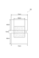
- a support film for evaluating a tensile stress-strain curve having a long side of 70 mm ⁇ a short side of 50 mm ⁇ 0.100 mm (thickness) on two sides of the cut adhesive laminate As a support film for evaluating a tensile stress-strain curve having a long side of 70 mm ⁇ a short side of 50 mm ⁇ 0.100 mm (thickness) on two sides of the cut adhesive laminate, a polyethylene terephthalate film (manufactured by Toyobo Co., Ltd., Cosmo Shine A4300) is used. At 25 ° C. and atmospheric pressure on the long side, a rubber roller (roller diameter: 50 mm, roller width: 210 mm) was applied at a pressure of 0.07 MPa, and the size of the adhesive layer not bonded was 10 mm in length. X The width was set to 50 mm.
- the heavy release separator on the other adhesive layer side that was not bonded to the polyethylene terephthalate film was peeled off to produce a tensile stress-strain curve support film 101 shown in FIG.
- the sample obtained above was measured with a tensile tester (Orientec Co., Ltd., RTC-1210 [trade name]), and the polyethylene terephthalate part of the sample was picked and measured in a 23 ° C. environment at a tensile speed of 300 mm / min. A tensile stress-strain curve was obtained. An example of the obtained tensile stress-strain curve is shown in FIG.
- Step embedding evaluation The produced pressure-sensitive adhesive laminate was cut into a size of 50 mm ⁇ 80 mm ⁇ 0.125 mm.
- the rubber laminate (roller diameter: 50 mm, roller width: 210 mm) was placed on an ITO film of 58 mm ⁇ 86 mm ⁇ 0.125 mm (thickness) on an ITO film (Toyobo Co., Ltd., 300R) at 25 ° C. and atmospheric pressure. was applied at a pressure of 0.07 MPa.
- a pressure-sensitive adhesive sheet is sandwiched between a glass substrate (thickness 0.7 mm) having a stepped portion with an outer peripheral portion printed so as to have a thickness of 35 ⁇ m on the other adhesive layer side to which the ITO film is not bonded.
- a rubber roller roller diameter: 50 mm, roller width: 210 mm
- step-difference part by which the outer peripheral part was printed has the same outer dimension as an ITO film, and has an opening part with an internal dimension of 45 mm x 68 mm.
- the glass substrate was used as a substitute for an input device or an image display device, and the embeddability was evaluated. Thereafter, autoclaving (45 ° C., 0.5 MPa) was performed for 20 minutes to obtain a sample. The obtained sample was left under the following environmental conditions, and a sample treated for a predetermined time was taken out and evaluated.
- An adhesive layer 2 is formed to have a thickness of 125 ⁇ m on the heavy release separator 3 (Toray Film Processing Co., Ltd., Therapy BX8, 50 ⁇ m) shown in FIG. 4 (Toray Film Processing Co., Ltd., therapy BKE, 50 ⁇ m) was formed into a 100 mm ⁇ 200 mm adhesive laminate, and a flat plate punching type punching device (manufactured by Taiwan Manei Machinery Co., Ltd.) A sample of an adhesive laminate was punched at 25 ° C.
- the prepared adhesive laminate was cut into a size of 50 mm ⁇ 50 mm ⁇ 0.125 mm (thickness).
- the cut-out pressure sensitive adhesive sheet was allowed to stand at 85 ° C. and 85% RH for 24 hours, and then the pressure sensitive adhesive sheet was taken out and using a turbidimeter (manufactured by Nippon Denshoku Industries Co., Ltd., NDH-5000) in an OCA single layer state. Measured.
- the produced pressure-sensitive adhesive sheet was cut into a size of 30 mm ⁇ 30 mm ⁇ 0.125 mm (thickness).
- the cut adhesive sheet was stuck on soda lime glass (thickness 0.5 mm) to prepare a test piece.
- the light transmittance in the wavelength range of 200 to 800 nm of the prepared test piece was measured using an ultraviolet-visible-near infrared spectrophotometer (manufactured by JASCO Corporation, instrument name “V570”), and the light transmittance at 380 nm was read. .
- the measurement of the weight average molecular weight was performed using the gel permeation chromatography which used tetrahydrofuran (THF) as a solvent, and it determined using the calibration curve of a standard polystyrene using the following apparatus and measurement conditions.
- Equipment Hitachi, Ltd.
- RI detector L-3350
- Solvent THF
- Column Gelpac GL-R420 + R430 + R440 manufactured by Hitachi Chemical Co., Ltd.
- Production Example 2 Synthesis of (A) (meth) acrylic acid derivative polymer A-2 In a reaction vessel equipped with a cooling tube, a thermometer, a stirrer, a dropping funnel and a nitrogen introduction tube, 2-ethylhexyl acrylate 36 as an initial monomer 0.0 g, 12.0 g of isobornyl acrylate (IBXA), 9.0 g of 2-hydroxyethyl acrylate, 3.0 g of methyl methacrylate, 100.0 g of ethyl acetate, and 20 g of toluene, while substituting nitrogen with an air volume of 100 mL / min And heated from room temperature (25 ° C.) to 80 ° C. in 15 minutes.
- IBXA isobornyl acrylate
- Production Example 4 Synthesis of (A) (meth) acrylic acid derivative polymer A-4 Into a reaction vessel equipped with a cooling tube, a thermometer, a stirrer, a dropping funnel and a nitrogen introducing tube, 2-ethylhexyl acrylate 36 as an initial monomer 0.0 g, 15.0 g of isobornyl acrylate, 9.0 g of 2-hydroxyethyl acrylate, 100.0 g of ethyl acetate, and 20 g of toluene, and at room temperature (25 ° C.) for 15 minutes while substituting nitrogen with an air volume of 100 mL / min To 80 ° C.
- the measurement of the weight average molecular weight was performed using the gel permeation chromatography which used tetrahydrofuran (THF) as a solvent, and it determined using the calibration curve of a standard polystyrene using the following apparatus and measurement conditions.
- Equipment Hitachi, Ltd.
- RI detector L-3350
- Solvent THF
- Column Gelpac GL-R420 + R430 + R440 manufactured by Hitachi Chemical Co., Ltd.
- Production Example 5 Synthesis of (A) (meth) acrylic acid derivative polymer A-5 2-ethylhexyl acrylate 36 as an initial monomer was placed in a reaction vessel equipped with a cooling tube, a thermometer, a stirrer, a dropping funnel and a nitrogen introducing tube. 0.0 g, 15.0 g of methyl methacrylate, 9.0 g of 2-hydroxyethyl acrylate, 100.0 g of ethyl acetate, and 20 g of toluene, and the temperature was changed from room temperature (25 ° C.) to 80 in 15 minutes while purging with nitrogen at an air volume of 100 mL / min. Heated to ° C.
- the measurement of the weight average molecular weight was performed using the gel permeation chromatography which used tetrahydrofuran (THF) as a solvent, and it determined using the calibration curve of a standard polystyrene using the following apparatus and measurement conditions.
- Equipment Hitachi, Ltd.
- RI detector L-3350
- Solvent THF
- Column Gelpac GL-R420 + R430 + R440 manufactured by Hitachi Chemical Co., Ltd.
- the measurement of the weight average molecular weight was performed using the gel permeation chromatography which used tetrahydrofuran (THF) as a solvent, and it determined using the calibration curve of a standard polystyrene using the following apparatus and measurement conditions.
- Equipment Hitachi, Ltd.
- RI detector L-3350
- Solvent THF
- Column Gelpac GL-R420 + R430 + R440 manufactured by Hitachi Chemical Co., Ltd.
- Example 1 A polyfunctional hexamethylene diisocyanate compound (Nippon Polyurethane Industry Co., Ltd., Coronate) was used as a thermal crosslinking agent for the solid content of 99.8 parts by mass of the (meth) acrylic acid derivative polymer A-1 solution obtained in Production Example 1. HL) 0.2 parts by mass was weighed and mixed by stirring to obtain an adhesive resin composition for an adhesive sheet. Thereafter, the pressure-sensitive adhesive resin composition for pressure-sensitive adhesive sheet obtained above was dropped onto a polyethylene terephthalate film subjected to mold release treatment on the surface, and applied using a bar coater so that the thickness after drying was 125 ⁇ m.
- Example 2 A pressure-sensitive adhesive laminate was obtained in the same manner as in Example 1 except that the acrylic acid derivative polymer A-2 obtained in Production Example 2 was used in place of the (meth) acrylic acid derivative polymer A-1. The results evaluated in the same manner as in Example 1 are shown in Table 1.
- Example 3 An adhesive laminate was obtained in the same manner as in Example 1 except that the acrylic acid derivative polymer A-3 obtained in Production Example 3 was used instead of the (meth) acrylic acid derivative polymer A-1. The results evaluated in the same manner as in Example 1 are shown in Table 1.
- Example 4 In Example 3, 0.8 parts by mass of benzotriazole compound 1 (manufactured by BASF Japan, Tinuvin 326) and 1.0 part by mass of benzotriazole compound 2 (manufactured by BASF Japan, Tinuvin 928) were weighed as UV absorbers. The obtained pressure-sensitive adhesive resin composition for pressure-sensitive adhesive sheets was stirred and mixed to obtain a resin composition for pressure-sensitive adhesive sheets. The results evaluated in the same manner as in Example 1 are shown in Table 1.
- Comparative Examples 1 and 2 The same procedure as in Example 1 was conducted except that the acrylic acid derivative polymer A-4 obtained in Production Example 4 was used instead of the (meth) acrylic acid derivative polymer A-1 and the formulation shown in Table 1 was used. An adhesive laminate was obtained. The results evaluated in the same manner as in Example 1 are shown in Table 1.
- Comparative Example 3 A pressure-sensitive adhesive laminate was obtained in the same manner as in Example 1 except that the acrylic acid derivative polymer A-5 obtained in Production Example 5 was used in place of the (meth) acrylic acid derivative polymer A-1. The results evaluated in the same manner as in Example 1 are shown in Table 1.
- Comparative Examples 4 and 5 The same procedure as in Example 1 was conducted except that the acrylic acid derivative polymer A-6 obtained in Production Example 6 was used in place of the (meth) acrylic acid derivative polymer A-1, and the formulation shown in Table 1 was used. To obtain an adhesive laminate. The results evaluated in the same manner as in Example 1 are shown in Table 1.
- SYMBOLS 1A, 1B Adhesive laminated body, 2 ... Adhesive layer, 3 ... Heavy release separator, 4 ... Light release separator, 5 ... Carrier film, 2a, 3a, 4a, 5a ... Outer edge, 40 ... Transparent protective board (glass or plastic substrate) , 7 ... Image display unit, 12 ... Liquid crystal display cell, 20, 22 ... Polarizing plate, 30 ... Touch panel, 31, 32 ... Transparent resin layer, 50 ... Backlight system, 60 ... Stepped part, 100 ... Jig, 101 ... Support film for tensile stress-strain curve evaluation.
Landscapes
- Physics & Mathematics (AREA)
- Chemical & Material Sciences (AREA)
- Engineering & Computer Science (AREA)
- Organic Chemistry (AREA)
- General Physics & Mathematics (AREA)
- Theoretical Computer Science (AREA)
- General Engineering & Computer Science (AREA)
- Nonlinear Science (AREA)
- Mathematical Physics (AREA)
- Crystallography & Structural Chemistry (AREA)
- Human Computer Interaction (AREA)
- Optics & Photonics (AREA)
- Adhesive Tapes (AREA)
- Adhesives Or Adhesive Processes (AREA)
- Liquid Crystal (AREA)
- Devices For Indicating Variable Information By Combining Individual Elements (AREA)
- Laminated Bodies (AREA)
Abstract
L'invention concerne une feuille adhésive pour un dispositif d'affichage d'image, où la valeur tan δ entre 40 et 70 °C est supérieure ou égale à 0,35, le module de traction sécant dans la courbe contrainte-déformation à la traction est compris entre 0,6 et 1,4 MPa, et l'allongement en traction à la rupture est inférieur ou égal à 150 mm.
Applications Claiming Priority (2)
| Application Number | Priority Date | Filing Date | Title |
|---|---|---|---|
| JP2015-053888 | 2015-03-17 | ||
| JP2015053888A JP2018083851A (ja) | 2015-03-17 | 2015-03-17 | 画像表示装置用粘着シート、画像表示装置用粘着積層体及び画像表示装置 |
Publications (1)
| Publication Number | Publication Date |
|---|---|
| WO2016148208A1 true WO2016148208A1 (fr) | 2016-09-22 |
Family
ID=56919045
Family Applications (1)
| Application Number | Title | Priority Date | Filing Date |
|---|---|---|---|
| PCT/JP2016/058399 Ceased WO2016148208A1 (fr) | 2015-03-17 | 2016-03-16 | Feuille adhésive pour dispositif d'affichage d'image, corps stratifié adhésif pour dispositif d'affichage d'image, et dispositif d'affichage d'image |
Country Status (3)
| Country | Link |
|---|---|
| JP (1) | JP2018083851A (fr) |
| TW (1) | TW201639936A (fr) |
| WO (1) | WO2016148208A1 (fr) |
Cited By (2)
| Publication number | Priority date | Publication date | Assignee | Title |
|---|---|---|---|---|
| CN111435581A (zh) * | 2019-01-14 | 2020-07-21 | 三星显示有限公司 | 保护带和包括该保护带的显示设备 |
| JP2021505934A (ja) * | 2017-12-20 | 2021-02-18 | エルジー・ケム・リミテッド | 透過度可変フィルム及びその用途 |
Families Citing this family (2)
| Publication number | Priority date | Publication date | Assignee | Title |
|---|---|---|---|---|
| JP6603378B2 (ja) * | 2018-09-05 | 2019-11-06 | リンテック株式会社 | 表示体 |
| JP6846497B2 (ja) * | 2019-02-14 | 2021-03-24 | 住友化学株式会社 | 粘着剤層付光学積層フィルム及びその製造方法 |
Citations (9)
| Publication number | Priority date | Publication date | Assignee | Title |
|---|---|---|---|---|
| JP2011074380A (ja) * | 2009-09-07 | 2011-04-14 | Lintec Corp | 保護フィルム及び保護フィルムの製造方法 |
| JP2011099078A (ja) * | 2009-11-09 | 2011-05-19 | Nitto Denko Corp | 光学用粘着シート |
| WO2011115224A1 (fr) * | 2010-03-18 | 2011-09-22 | 積水化学工業株式会社 | Composition d'adhésif autocollant pour éléments optiques et ruban adhésif autocollant pour éléments optiques |
| JP2012072299A (ja) * | 2010-09-29 | 2012-04-12 | Lintec Corp | 両面粘着テープ及びタッチパネル付き表示装置 |
| WO2012165625A1 (fr) * | 2011-06-02 | 2012-12-06 | Dic株式会社 | Composition d'agent adhésif facilement retirable et ruban adhésid facilement retirable |
| WO2013168773A1 (fr) * | 2012-05-10 | 2013-11-14 | 富士フイルム株式会社 | Stratifié de film conducteur, panneau tactile, tableau de connexions, appareil électronique, feuille transparente adhésive double face sensible à la pression et feuille transparente adhésive sensible à la pression |
| JP2014224179A (ja) * | 2013-05-15 | 2014-12-04 | 日立化成株式会社 | 画像表示装置用粘着剤、画像表示装置用粘着シート、及びこれらを用いた画像表示装置の製造方法 |
| JP2015030765A (ja) * | 2013-07-31 | 2015-02-16 | 日東電工株式会社 | 粘着シート、粘着層付き光学フィルム、および画像表示装置 |
| JP2016074761A (ja) * | 2014-10-02 | 2016-05-12 | 日本カーバイド工業株式会社 | 粘着剤及び粘着シート |
-
2015
- 2015-03-17 JP JP2015053888A patent/JP2018083851A/ja active Pending
-
2016
- 2016-03-16 WO PCT/JP2016/058399 patent/WO2016148208A1/fr not_active Ceased
- 2016-03-17 TW TW105108311A patent/TW201639936A/zh unknown
Patent Citations (9)
| Publication number | Priority date | Publication date | Assignee | Title |
|---|---|---|---|---|
| JP2011074380A (ja) * | 2009-09-07 | 2011-04-14 | Lintec Corp | 保護フィルム及び保護フィルムの製造方法 |
| JP2011099078A (ja) * | 2009-11-09 | 2011-05-19 | Nitto Denko Corp | 光学用粘着シート |
| WO2011115224A1 (fr) * | 2010-03-18 | 2011-09-22 | 積水化学工業株式会社 | Composition d'adhésif autocollant pour éléments optiques et ruban adhésif autocollant pour éléments optiques |
| JP2012072299A (ja) * | 2010-09-29 | 2012-04-12 | Lintec Corp | 両面粘着テープ及びタッチパネル付き表示装置 |
| WO2012165625A1 (fr) * | 2011-06-02 | 2012-12-06 | Dic株式会社 | Composition d'agent adhésif facilement retirable et ruban adhésid facilement retirable |
| WO2013168773A1 (fr) * | 2012-05-10 | 2013-11-14 | 富士フイルム株式会社 | Stratifié de film conducteur, panneau tactile, tableau de connexions, appareil électronique, feuille transparente adhésive double face sensible à la pression et feuille transparente adhésive sensible à la pression |
| JP2014224179A (ja) * | 2013-05-15 | 2014-12-04 | 日立化成株式会社 | 画像表示装置用粘着剤、画像表示装置用粘着シート、及びこれらを用いた画像表示装置の製造方法 |
| JP2015030765A (ja) * | 2013-07-31 | 2015-02-16 | 日東電工株式会社 | 粘着シート、粘着層付き光学フィルム、および画像表示装置 |
| JP2016074761A (ja) * | 2014-10-02 | 2016-05-12 | 日本カーバイド工業株式会社 | 粘着剤及び粘着シート |
Cited By (6)
| Publication number | Priority date | Publication date | Assignee | Title |
|---|---|---|---|---|
| JP2021505934A (ja) * | 2017-12-20 | 2021-02-18 | エルジー・ケム・リミテッド | 透過度可変フィルム及びその用途 |
| US11262636B2 (en) | 2017-12-20 | 2022-03-01 | Lg Chem, Ltd. | Transmittance-variable film and use thereof |
| JP7155495B2 (ja) | 2017-12-20 | 2022-10-19 | エルジー・ケム・リミテッド | 透過度可変フィルム及びその用途 |
| CN111435581A (zh) * | 2019-01-14 | 2020-07-21 | 三星显示有限公司 | 保护带和包括该保护带的显示设备 |
| CN111554193A (zh) * | 2019-01-14 | 2020-08-18 | 三星显示有限公司 | 保护带和包括该保护带的显示设备 |
| US11807784B2 (en) | 2019-01-14 | 2023-11-07 | Samsung Display Co., Ltd. | Protective tape and display device including the same |
Also Published As
| Publication number | Publication date |
|---|---|
| JP2018083851A (ja) | 2018-05-31 |
| TW201639936A (zh) | 2016-11-16 |
Similar Documents
| Publication | Publication Date | Title |
|---|---|---|
| JP6065002B2 (ja) | 画像表示装置用粘着シート、画像表示装置の製造方法及び画像表示装置 | |
| JP6265907B2 (ja) | 画像表示装置用粘着シート、画像表示装置の製造方法及び画像表示装置 | |
| JP6197899B2 (ja) | 光学用粘着材樹脂組成物、光学用粘着材シート、画像表示装置、光学用粘着材シートの製造方法及び画像表示装置の製造方法 | |
| JP6246469B2 (ja) | 画像表示装置用粘着シート、画像表示装置の製造方法及び画像表示装置 | |
| JP6340765B2 (ja) | 両面粘着シートおよび画像表示装置 | |
| JP2017019903A (ja) | 画像表示装置用粘着シート、画像表示装置の製造方法及び画像表示装置 | |
| JP2014125524A (ja) | 画像表示装置用粘着シート、画像表示装置の製造方法及び画像表示装置 | |
| WO2012077808A1 (fr) | Feuille adhésive pour dispositif d'affichage d'image, dispositif d'affichage d'image et composition de résine adhésive | |
| JP2014224179A (ja) | 画像表示装置用粘着剤、画像表示装置用粘着シート、及びこれらを用いた画像表示装置の製造方法 | |
| JP6048137B2 (ja) | 画像表示装置用粘着シート及び画像表示装置 | |
| JP5991531B2 (ja) | 画像表示装置用粘着シートの製造方法 | |
| JP2017002260A (ja) | 画像表示装置用粘着シート、画像表示装置の製造方法及び画像表示装置 | |
| JP2016069529A (ja) | 画像表示装置用粘着シート、画像表示装置の製造方法及び画像表示装置 | |
| JP2016050245A (ja) | 画像表示装置用粘着シート、画像表示装置用粘着シート部材、画像表示装置の製造方法及び画像表示装置 | |
| WO2016148208A1 (fr) | Feuille adhésive pour dispositif d'affichage d'image, corps stratifié adhésif pour dispositif d'affichage d'image, et dispositif d'affichage d'image | |
| KR20230133296A (ko) | 화상 표시 장치용 점착 시트, 이형 필름을 가지는 점착시트, 화상 표시 장치용 적층체 및 화상 표시 장치 | |
| JP2016071161A (ja) | 画像表示装置用粘着シート、画像表示装置の製造方法及び画像表示装置 | |
| JP2014094977A (ja) | 画像表示装置用粘着シート、画像表示装置の製造方法及び画像表示装置 | |
| WO2015140900A1 (fr) | Feuille adhésive pour dispositif d'affichage d'image, procédé de fabrication de dispositif d'affichage d'image l'utilisant, et dispositif d'affichage d'image | |
| JP2015229687A (ja) | 画像表示装置用粘着シート、画像表示装置の製造方法及び画像表示装置 | |
| JP6155793B2 (ja) | 画像表示装置用粘着剤組成物、画像表示装置用粘着シート及びそれを用いた画像表示装置 | |
| WO2015132876A1 (fr) | Feuille adhésive pour dispositif d'affichage d'images, et procédé de production de dispositif d'affichage d'images et dispositif d'affichage d'images l'utilisant |
Legal Events
| Date | Code | Title | Description |
|---|---|---|---|
| 121 | Ep: the epo has been informed by wipo that ep was designated in this application |
Ref document number: 16765037 Country of ref document: EP Kind code of ref document: A1 |
|
| NENP | Non-entry into the national phase |
Ref country code: DE |
|
| 122 | Ep: pct application non-entry in european phase |
Ref document number: 16765037 Country of ref document: EP Kind code of ref document: A1 |
|
| NENP | Non-entry into the national phase |
Ref country code: JP |