WO2016151663A1 - Dispositif de régulation de vitesse de véhicule par récupération - Google Patents
Dispositif de régulation de vitesse de véhicule par récupération Download PDFInfo
- Publication number
- WO2016151663A1 WO2016151663A1 PCT/JP2015/058407 JP2015058407W WO2016151663A1 WO 2016151663 A1 WO2016151663 A1 WO 2016151663A1 JP 2015058407 W JP2015058407 W JP 2015058407W WO 2016151663 A1 WO2016151663 A1 WO 2016151663A1
- Authority
- WO
- WIPO (PCT)
- Prior art keywords
- brake
- rotational speed
- regenerative
- shift control
- vehicle
- Prior art date
- Legal status (The legal status is an assumption and is not a legal conclusion. Google has not performed a legal analysis and makes no representation as to the accuracy of the status listed.)
- Ceased
Links
Images




Classifications
-
- B—PERFORMING OPERATIONS; TRANSPORTING
- B60—VEHICLES IN GENERAL
- B60W—CONJOINT CONTROL OF VEHICLE SUB-UNITS OF DIFFERENT TYPE OR DIFFERENT FUNCTION; CONTROL SYSTEMS SPECIALLY ADAPTED FOR HYBRID VEHICLES; ROAD VEHICLE DRIVE CONTROL SYSTEMS FOR PURPOSES NOT RELATED TO THE CONTROL OF A PARTICULAR SUB-UNIT
- B60W20/00—Control systems specially adapted for hybrid vehicles
- B60W20/10—Controlling the power contribution of each of the prime movers to meet required power demand
- B60W20/13—Controlling the power contribution of each of the prime movers to meet required power demand in order to stay within battery power input or output limits; in order to prevent overcharging or battery depletion
- B60W20/14—Controlling the power contribution of each of the prime movers to meet required power demand in order to stay within battery power input or output limits; in order to prevent overcharging or battery depletion in conjunction with braking regeneration
-
- B—PERFORMING OPERATIONS; TRANSPORTING
- B60—VEHICLES IN GENERAL
- B60K—ARRANGEMENT OR MOUNTING OF PROPULSION UNITS OR OF TRANSMISSIONS IN VEHICLES; ARRANGEMENT OR MOUNTING OF PLURAL DIVERSE PRIME-MOVERS IN VEHICLES; AUXILIARY DRIVES FOR VEHICLES; INSTRUMENTATION OR DASHBOARDS FOR VEHICLES; ARRANGEMENTS IN CONNECTION WITH COOLING, AIR INTAKE, GAS EXHAUST OR FUEL SUPPLY OF PROPULSION UNITS IN VEHICLES
- B60K6/00—Arrangement or mounting of plural diverse prime-movers for mutual or common propulsion, e.g. hybrid propulsion systems comprising electric motors and internal combustion engines
- B60K6/20—Arrangement or mounting of plural diverse prime-movers for mutual or common propulsion, e.g. hybrid propulsion systems comprising electric motors and internal combustion engines the prime-movers consisting of electric motors and internal combustion engines, e.g. HEVs
- B60K6/50—Architecture of the driveline characterised by arrangement or kind of transmission units
- B60K6/54—Transmission for changing ratio
- B60K6/543—Transmission for changing ratio the transmission being a continuously variable transmission
-
- B—PERFORMING OPERATIONS; TRANSPORTING
- B60—VEHICLES IN GENERAL
- B60W—CONJOINT CONTROL OF VEHICLE SUB-UNITS OF DIFFERENT TYPE OR DIFFERENT FUNCTION; CONTROL SYSTEMS SPECIALLY ADAPTED FOR HYBRID VEHICLES; ROAD VEHICLE DRIVE CONTROL SYSTEMS FOR PURPOSES NOT RELATED TO THE CONTROL OF A PARTICULAR SUB-UNIT
- B60W10/00—Conjoint control of vehicle sub-units of different type or different function
- B60W10/04—Conjoint control of vehicle sub-units of different type or different function including control of propulsion units
- B60W10/06—Conjoint control of vehicle sub-units of different type or different function including control of propulsion units including control of combustion engines
-
- B—PERFORMING OPERATIONS; TRANSPORTING
- B60—VEHICLES IN GENERAL
- B60W—CONJOINT CONTROL OF VEHICLE SUB-UNITS OF DIFFERENT TYPE OR DIFFERENT FUNCTION; CONTROL SYSTEMS SPECIALLY ADAPTED FOR HYBRID VEHICLES; ROAD VEHICLE DRIVE CONTROL SYSTEMS FOR PURPOSES NOT RELATED TO THE CONTROL OF A PARTICULAR SUB-UNIT
- B60W10/00—Conjoint control of vehicle sub-units of different type or different function
- B60W10/04—Conjoint control of vehicle sub-units of different type or different function including control of propulsion units
- B60W10/08—Conjoint control of vehicle sub-units of different type or different function including control of propulsion units including control of electric propulsion units, e.g. motors or generators
-
- B—PERFORMING OPERATIONS; TRANSPORTING
- B60—VEHICLES IN GENERAL
- B60W—CONJOINT CONTROL OF VEHICLE SUB-UNITS OF DIFFERENT TYPE OR DIFFERENT FUNCTION; CONTROL SYSTEMS SPECIALLY ADAPTED FOR HYBRID VEHICLES; ROAD VEHICLE DRIVE CONTROL SYSTEMS FOR PURPOSES NOT RELATED TO THE CONTROL OF A PARTICULAR SUB-UNIT
- B60W10/00—Conjoint control of vehicle sub-units of different type or different function
- B60W10/10—Conjoint control of vehicle sub-units of different type or different function including control of change-speed gearings
- B60W10/101—Infinitely variable gearings
- B60W10/107—Infinitely variable gearings with endless flexible members
-
- B—PERFORMING OPERATIONS; TRANSPORTING
- B60—VEHICLES IN GENERAL
- B60W—CONJOINT CONTROL OF VEHICLE SUB-UNITS OF DIFFERENT TYPE OR DIFFERENT FUNCTION; CONTROL SYSTEMS SPECIALLY ADAPTED FOR HYBRID VEHICLES; ROAD VEHICLE DRIVE CONTROL SYSTEMS FOR PURPOSES NOT RELATED TO THE CONTROL OF A PARTICULAR SUB-UNIT
- B60W10/00—Conjoint control of vehicle sub-units of different type or different function
- B60W10/18—Conjoint control of vehicle sub-units of different type or different function including control of braking systems
- B60W10/184—Conjoint control of vehicle sub-units of different type or different function including control of braking systems with wheel brakes
-
- B—PERFORMING OPERATIONS; TRANSPORTING
- B60—VEHICLES IN GENERAL
- B60W—CONJOINT CONTROL OF VEHICLE SUB-UNITS OF DIFFERENT TYPE OR DIFFERENT FUNCTION; CONTROL SYSTEMS SPECIALLY ADAPTED FOR HYBRID VEHICLES; ROAD VEHICLE DRIVE CONTROL SYSTEMS FOR PURPOSES NOT RELATED TO THE CONTROL OF A PARTICULAR SUB-UNIT
- B60W10/00—Conjoint control of vehicle sub-units of different type or different function
- B60W10/18—Conjoint control of vehicle sub-units of different type or different function including control of braking systems
- B60W10/196—Conjoint control of vehicle sub-units of different type or different function including control of braking systems acting within the driveline, e.g. retarders
-
- B—PERFORMING OPERATIONS; TRANSPORTING
- B60—VEHICLES IN GENERAL
- B60W—CONJOINT CONTROL OF VEHICLE SUB-UNITS OF DIFFERENT TYPE OR DIFFERENT FUNCTION; CONTROL SYSTEMS SPECIALLY ADAPTED FOR HYBRID VEHICLES; ROAD VEHICLE DRIVE CONTROL SYSTEMS FOR PURPOSES NOT RELATED TO THE CONTROL OF A PARTICULAR SUB-UNIT
- B60W10/00—Conjoint control of vehicle sub-units of different type or different function
- B60W10/24—Conjoint control of vehicle sub-units of different type or different function including control of energy storage means
- B60W10/26—Conjoint control of vehicle sub-units of different type or different function including control of energy storage means for electrical energy, e.g. batteries or capacitors
-
- B—PERFORMING OPERATIONS; TRANSPORTING
- B60—VEHICLES IN GENERAL
- B60W—CONJOINT CONTROL OF VEHICLE SUB-UNITS OF DIFFERENT TYPE OR DIFFERENT FUNCTION; CONTROL SYSTEMS SPECIALLY ADAPTED FOR HYBRID VEHICLES; ROAD VEHICLE DRIVE CONTROL SYSTEMS FOR PURPOSES NOT RELATED TO THE CONTROL OF A PARTICULAR SUB-UNIT
- B60W10/00—Conjoint control of vehicle sub-units of different type or different function
- B60W10/30—Conjoint control of vehicle sub-units of different type or different function including control of auxiliary equipment, e.g. air-conditioning compressors or oil pumps
-
- B—PERFORMING OPERATIONS; TRANSPORTING
- B60—VEHICLES IN GENERAL
- B60W—CONJOINT CONTROL OF VEHICLE SUB-UNITS OF DIFFERENT TYPE OR DIFFERENT FUNCTION; CONTROL SYSTEMS SPECIALLY ADAPTED FOR HYBRID VEHICLES; ROAD VEHICLE DRIVE CONTROL SYSTEMS FOR PURPOSES NOT RELATED TO THE CONTROL OF A PARTICULAR SUB-UNIT
- B60W20/00—Control systems specially adapted for hybrid vehicles
- B60W20/30—Control strategies involving selection of transmission gear ratio
-
- B—PERFORMING OPERATIONS; TRANSPORTING
- B60—VEHICLES IN GENERAL
- B60W—CONJOINT CONTROL OF VEHICLE SUB-UNITS OF DIFFERENT TYPE OR DIFFERENT FUNCTION; CONTROL SYSTEMS SPECIALLY ADAPTED FOR HYBRID VEHICLES; ROAD VEHICLE DRIVE CONTROL SYSTEMS FOR PURPOSES NOT RELATED TO THE CONTROL OF A PARTICULAR SUB-UNIT
- B60W30/00—Purposes of road vehicle drive control systems not related to the control of a particular sub-unit, e.g. of systems using conjoint control of vehicle sub-units
- B60W30/18—Propelling the vehicle
- B60W30/18009—Propelling the vehicle related to particular drive situations
- B60W30/18109—Braking
- B60W30/18127—Regenerative braking
-
- B—PERFORMING OPERATIONS; TRANSPORTING
- B60—VEHICLES IN GENERAL
- B60W—CONJOINT CONTROL OF VEHICLE SUB-UNITS OF DIFFERENT TYPE OR DIFFERENT FUNCTION; CONTROL SYSTEMS SPECIALLY ADAPTED FOR HYBRID VEHICLES; ROAD VEHICLE DRIVE CONTROL SYSTEMS FOR PURPOSES NOT RELATED TO THE CONTROL OF A PARTICULAR SUB-UNIT
- B60W30/00—Purposes of road vehicle drive control systems not related to the control of a particular sub-unit, e.g. of systems using conjoint control of vehicle sub-units
- B60W30/18—Propelling the vehicle
- B60W30/20—Reducing vibrations in the driveline
-
- F—MECHANICAL ENGINEERING; LIGHTING; HEATING; WEAPONS; BLASTING
- F16—ENGINEERING ELEMENTS AND UNITS; GENERAL MEASURES FOR PRODUCING AND MAINTAINING EFFECTIVE FUNCTIONING OF MACHINES OR INSTALLATIONS; THERMAL INSULATION IN GENERAL
- F16H—GEARING
- F16H61/00—Control functions within control units of change-speed- or reversing-gearings for conveying rotary motion ; Control of exclusively fluid gearing, friction gearing, gearings with endless flexible members or other particular types of gearing
- F16H61/04—Smoothing ratio shift
-
- B—PERFORMING OPERATIONS; TRANSPORTING
- B60—VEHICLES IN GENERAL
- B60K—ARRANGEMENT OR MOUNTING OF PROPULSION UNITS OR OF TRANSMISSIONS IN VEHICLES; ARRANGEMENT OR MOUNTING OF PLURAL DIVERSE PRIME-MOVERS IN VEHICLES; AUXILIARY DRIVES FOR VEHICLES; INSTRUMENTATION OR DASHBOARDS FOR VEHICLES; ARRANGEMENTS IN CONNECTION WITH COOLING, AIR INTAKE, GAS EXHAUST OR FUEL SUPPLY OF PROPULSION UNITS IN VEHICLES
- B60K6/00—Arrangement or mounting of plural diverse prime-movers for mutual or common propulsion, e.g. hybrid propulsion systems comprising electric motors and internal combustion engines
- B60K6/20—Arrangement or mounting of plural diverse prime-movers for mutual or common propulsion, e.g. hybrid propulsion systems comprising electric motors and internal combustion engines the prime-movers consisting of electric motors and internal combustion engines, e.g. HEVs
- B60K6/42—Arrangement or mounting of plural diverse prime-movers for mutual or common propulsion, e.g. hybrid propulsion systems comprising electric motors and internal combustion engines the prime-movers consisting of electric motors and internal combustion engines, e.g. HEVs characterised by the architecture of the hybrid electric vehicle
- B60K6/48—Parallel type
- B60K2006/4825—Electric machine connected or connectable to gearbox input shaft
-
- B—PERFORMING OPERATIONS; TRANSPORTING
- B60—VEHICLES IN GENERAL
- B60W—CONJOINT CONTROL OF VEHICLE SUB-UNITS OF DIFFERENT TYPE OR DIFFERENT FUNCTION; CONTROL SYSTEMS SPECIALLY ADAPTED FOR HYBRID VEHICLES; ROAD VEHICLE DRIVE CONTROL SYSTEMS FOR PURPOSES NOT RELATED TO THE CONTROL OF A PARTICULAR SUB-UNIT
- B60W2520/00—Input parameters relating to overall vehicle dynamics
- B60W2520/10—Longitudinal speed
-
- B—PERFORMING OPERATIONS; TRANSPORTING
- B60—VEHICLES IN GENERAL
- B60W—CONJOINT CONTROL OF VEHICLE SUB-UNITS OF DIFFERENT TYPE OR DIFFERENT FUNCTION; CONTROL SYSTEMS SPECIALLY ADAPTED FOR HYBRID VEHICLES; ROAD VEHICLE DRIVE CONTROL SYSTEMS FOR PURPOSES NOT RELATED TO THE CONTROL OF A PARTICULAR SUB-UNIT
- B60W2540/00—Input parameters relating to occupants
- B60W2540/12—Brake pedal position
-
- B—PERFORMING OPERATIONS; TRANSPORTING
- B60—VEHICLES IN GENERAL
- B60W—CONJOINT CONTROL OF VEHICLE SUB-UNITS OF DIFFERENT TYPE OR DIFFERENT FUNCTION; CONTROL SYSTEMS SPECIALLY ADAPTED FOR HYBRID VEHICLES; ROAD VEHICLE DRIVE CONTROL SYSTEMS FOR PURPOSES NOT RELATED TO THE CONTROL OF A PARTICULAR SUB-UNIT
- B60W2710/00—Output or target parameters relating to a particular sub-units
- B60W2710/08—Electric propulsion units
- B60W2710/081—Speed
- B60W2710/082—Speed change rate
-
- B—PERFORMING OPERATIONS; TRANSPORTING
- B60—VEHICLES IN GENERAL
- B60W—CONJOINT CONTROL OF VEHICLE SUB-UNITS OF DIFFERENT TYPE OR DIFFERENT FUNCTION; CONTROL SYSTEMS SPECIALLY ADAPTED FOR HYBRID VEHICLES; ROAD VEHICLE DRIVE CONTROL SYSTEMS FOR PURPOSES NOT RELATED TO THE CONTROL OF A PARTICULAR SUB-UNIT
- B60W2710/00—Output or target parameters relating to a particular sub-units
- B60W2710/10—Change speed gearings
- B60W2710/1005—Transmission ratio engaged
-
- B—PERFORMING OPERATIONS; TRANSPORTING
- B60—VEHICLES IN GENERAL
- B60W—CONJOINT CONTROL OF VEHICLE SUB-UNITS OF DIFFERENT TYPE OR DIFFERENT FUNCTION; CONTROL SYSTEMS SPECIALLY ADAPTED FOR HYBRID VEHICLES; ROAD VEHICLE DRIVE CONTROL SYSTEMS FOR PURPOSES NOT RELATED TO THE CONTROL OF A PARTICULAR SUB-UNIT
- B60W2710/00—Output or target parameters relating to a particular sub-units
- B60W2710/10—Change speed gearings
- B60W2710/1011—Input shaft speed, e.g. turbine speed
-
- B—PERFORMING OPERATIONS; TRANSPORTING
- B60—VEHICLES IN GENERAL
- B60W—CONJOINT CONTROL OF VEHICLE SUB-UNITS OF DIFFERENT TYPE OR DIFFERENT FUNCTION; CONTROL SYSTEMS SPECIALLY ADAPTED FOR HYBRID VEHICLES; ROAD VEHICLE DRIVE CONTROL SYSTEMS FOR PURPOSES NOT RELATED TO THE CONTROL OF A PARTICULAR SUB-UNIT
- B60W2710/00—Output or target parameters relating to a particular sub-units
- B60W2710/10—Change speed gearings
- B60W2710/1011—Input shaft speed, e.g. turbine speed
- B60W2710/1016—Input speed change rate
-
- B—PERFORMING OPERATIONS; TRANSPORTING
- B60—VEHICLES IN GENERAL
- B60W—CONJOINT CONTROL OF VEHICLE SUB-UNITS OF DIFFERENT TYPE OR DIFFERENT FUNCTION; CONTROL SYSTEMS SPECIALLY ADAPTED FOR HYBRID VEHICLES; ROAD VEHICLE DRIVE CONTROL SYSTEMS FOR PURPOSES NOT RELATED TO THE CONTROL OF A PARTICULAR SUB-UNIT
- B60W2710/00—Output or target parameters relating to a particular sub-units
- B60W2710/10—Change speed gearings
- B60W2710/1038—Output speed
-
- B—PERFORMING OPERATIONS; TRANSPORTING
- B60—VEHICLES IN GENERAL
- B60W—CONJOINT CONTROL OF VEHICLE SUB-UNITS OF DIFFERENT TYPE OR DIFFERENT FUNCTION; CONTROL SYSTEMS SPECIALLY ADAPTED FOR HYBRID VEHICLES; ROAD VEHICLE DRIVE CONTROL SYSTEMS FOR PURPOSES NOT RELATED TO THE CONTROL OF A PARTICULAR SUB-UNIT
- B60W2720/00—Output or target parameters relating to overall vehicle dynamics
- B60W2720/10—Longitudinal speed
- B60W2720/106—Longitudinal acceleration
-
- B—PERFORMING OPERATIONS; TRANSPORTING
- B60—VEHICLES IN GENERAL
- B60Y—INDEXING SCHEME RELATING TO ASPECTS CROSS-CUTTING VEHICLE TECHNOLOGY
- B60Y2300/00—Purposes or special features of road vehicle drive control systems
- B60Y2300/18—Propelling the vehicle
- B60Y2300/19—Improvement of gear change, e.g. synchronisation or smoothing gear shift
-
- B—PERFORMING OPERATIONS; TRANSPORTING
- B60—VEHICLES IN GENERAL
- B60Y—INDEXING SCHEME RELATING TO ASPECTS CROSS-CUTTING VEHICLE TECHNOLOGY
- B60Y2300/00—Purposes or special features of road vehicle drive control systems
- B60Y2300/89—Repartition of braking force, e.g. friction braking versus regenerative braking
-
- Y—GENERAL TAGGING OF NEW TECHNOLOGICAL DEVELOPMENTS; GENERAL TAGGING OF CROSS-SECTIONAL TECHNOLOGIES SPANNING OVER SEVERAL SECTIONS OF THE IPC; TECHNICAL SUBJECTS COVERED BY FORMER USPC CROSS-REFERENCE ART COLLECTIONS [XRACs] AND DIGESTS
- Y02—TECHNOLOGIES OR APPLICATIONS FOR MITIGATION OR ADAPTATION AGAINST CLIMATE CHANGE
- Y02T—CLIMATE CHANGE MITIGATION TECHNOLOGIES RELATED TO TRANSPORTATION
- Y02T10/00—Road transport of goods or passengers
- Y02T10/60—Other road transportation technologies with climate change mitigation effect
- Y02T10/62—Hybrid vehicles
-
- Y—GENERAL TAGGING OF NEW TECHNOLOGICAL DEVELOPMENTS; GENERAL TAGGING OF CROSS-SECTIONAL TECHNOLOGIES SPANNING OVER SEVERAL SECTIONS OF THE IPC; TECHNICAL SUBJECTS COVERED BY FORMER USPC CROSS-REFERENCE ART COLLECTIONS [XRACs] AND DIGESTS
- Y10—TECHNICAL SUBJECTS COVERED BY FORMER USPC
- Y10S—TECHNICAL SUBJECTS COVERED BY FORMER USPC CROSS-REFERENCE ART COLLECTIONS [XRACs] AND DIGESTS
- Y10S903/00—Hybrid electric vehicles, HEVS
- Y10S903/902—Prime movers comprising electrical and internal combustion motors
- Y10S903/903—Prime movers comprising electrical and internal combustion motors having energy storing means, e.g. battery, capacitor
- Y10S903/904—Component specially adapted for hev
- Y10S903/915—Specific drive or transmission adapted for hev
- Y10S903/917—Specific drive or transmission adapted for hev with transmission for changing gear ratio
- Y10S903/918—Continuously variable
-
- Y—GENERAL TAGGING OF NEW TECHNOLOGICAL DEVELOPMENTS; GENERAL TAGGING OF CROSS-SECTIONAL TECHNOLOGIES SPANNING OVER SEVERAL SECTIONS OF THE IPC; TECHNICAL SUBJECTS COVERED BY FORMER USPC CROSS-REFERENCE ART COLLECTIONS [XRACs] AND DIGESTS
- Y10—TECHNICAL SUBJECTS COVERED BY FORMER USPC
- Y10S—TECHNICAL SUBJECTS COVERED BY FORMER USPC CROSS-REFERENCE ART COLLECTIONS [XRACs] AND DIGESTS
- Y10S903/00—Hybrid electric vehicles, HEVS
- Y10S903/902—Prime movers comprising electrical and internal combustion motors
- Y10S903/903—Prime movers comprising electrical and internal combustion motors having energy storing means, e.g. battery, capacitor
- Y10S903/947—Characterized by control of braking, e.g. blending of regeneration, friction braking
Definitions
- the present invention relates to a regenerative transmission control device for a vehicle that increases the rotational speed of a transmission input shaft to which an electric motor is connected by downshifting of a continuously variable transmission when there is a request to increase the regeneration amount during deceleration.
- the regenerative shift control when the regenerative shift control is performed based on, for example, a brake depressing operation in the brake transfer region due to the decrease in the vehicle speed during the cooperative regenerative control, an inertia shock occurs due to a sudden change in the actual transmission input rotation speed. That is, in the regenerative shift control performed to improve the regenerative efficiency, a downshift is performed in which the transmission input rotation speed command value is rapidly increased toward the target rotation speed of the regenerative brake, and when the target rotation speed is reached, the transmission An upshift is performed in which the input rotation speed command value is rapidly lowered along the target rotation speed.
- the regenerative shift control when the regenerative shift control is set to feedback shift control, the follow-up response of the actual transmission input rotational speed with respect to the transmission input rotational speed command value is delayed. For this reason, after the actual transmission input rotational speed increases rapidly, it turns back and rapidly decreases, and the actual transmission input rotational speed exceeds the target rotational speed. Due to this sudden change in the actual transmission input speed, an inertia shock occurs near the turn-up where the transmission input speed increases / decreases, and the driver who maintains a certain brake operation after stepping on feels uncomfortable. is there.
- An object of the present invention is to provide a regenerative shift control device for a vehicle that prevents a driver from feeling uncomfortable.
- the present invention includes a continuously variable transmission and an electric motor coupled to the input shaft side of the continuously variable transmission and regenerating energy during deceleration.
- the controller performs regenerative shift control that shifts the continuously variable transmission down to the low gear ratio side and increases the rotational speed of the transmission input shaft to which the motor is connected. Is provided.
- the controller performs regenerative shift control to increase the transmission input speed based on a request to increase the regeneration amount in the brake transfer area where the regenerative brake is switched to the mechanical brake due to a decrease in the vehicle speed, the speed change of the transmission input speed changes. Set speed limits.
- FIG. 1 is an overall system diagram illustrating an FF hybrid vehicle to which a regenerative shift control device according to a first embodiment is applied.
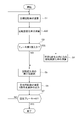
- 6 is a flowchart showing a flow of a regenerative shift control process executed in the hybrid control module of the first embodiment.
- FIG. 6 is a characteristic diagram showing the regeneration efficiency and the best efficiency ⁇ ray that are the basis for determining the relationship between the regeneration torque and the number of revolutions during regeneration in the regeneration shift control process of the first embodiment.
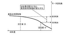
- FIG. 6 is a relationship characteristic diagram showing a relationship between a regeneration amount and a motor rotation speed by the best efficiency rotation used for calculating a target rotation speed in the regenerative shift control process of the first embodiment.
- Deceleration G vehicle speed, brake operation amount, Pri end command rotation speed, Pri end actual rotation speed, when performing regenerative shift control based on the brake depressing operation in the brake transfer area due to the decrease in vehicle speed in the regenerative shift control processing of the comparative example It is a time chart which shows each characteristic of a target number of rotations and a minimum number of rotations.
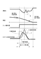
- the deceleration G, vehicle speed, brake operation amount, Pri-end command rotation speed, and Pri-end actual rotation speed when performing regenerative shift control based on the brake depressing operation in the brake change area due to the decrease in vehicle speed -It is a time chart which shows each characteristic of target rotation speed and minimum rotation speed.
- the regenerative shift control apparatus is applied to an FF hybrid vehicle (an example of a vehicle) in which left and right front wheels are drive wheels and a belt-type continuously variable transmission is mounted as a continuously variable transmission.
- FF hybrid vehicle an example of a vehicle
- left and right front wheels are drive wheels
- a belt-type continuously variable transmission is mounted as a continuously variable transmission.
- the configuration of the regenerative shift control device for the FF hybrid vehicle according to the first embodiment will be described by dividing it into an “overall system configuration” and a “regenerative shift control processing configuration”.
- FIG. 1 shows an overall system of an FF hybrid vehicle to which the regenerative shift control device of Embodiment 1 is applied.
- the overall system configuration of the FF hybrid vehicle will be described with reference to FIG.
- the drive system of the FF hybrid vehicle includes a horizontally placed engine 2, a first clutch 3 (abbreviated “CL1”), a motor generator 4 (abbreviated “MG”), and a second clutch 5 (abbreviated). "CL2”) and a belt type continuously variable transmission 6 (abbreviated as "CVT").
- the output shaft of the belt type continuously variable transmission 6 is drivingly connected to the left and right front wheels 10R and 10L via a final reduction gear train 7, a differential gear 8, and left and right drive shafts 9R and 9L.
- the left and right rear wheels 11R and 11L are driven wheels.
- the horizontal engine 2 is an engine disposed in a front room with a starter motor 1 and a crankshaft direction as a vehicle width direction, an electric water pump 12, and a crankshaft rotation sensor 13 for detecting reverse rotation of the horizontal engine 2.
- This horizontal engine 2 has an “MG start mode” in which cranking is performed by the motor generator 4 while the first clutch 3 is slidingly engaged, and a starter motor 1 which is powered by the 12V battery 22 as an engine starting method.
- Starter start mode ".
- the “starter start mode” is selected only when a limited condition such as a cryogenic temperature condition is satisfied.
- the motor generator 4 is a three-phase AC permanent magnet type synchronous motor connected to the transverse engine 2 via the first clutch 3.
- the motor generator 4 uses a high-power battery 21 described later as a power source, and an inverter 26 that converts direct current to three-phase alternating current during power running and converts three-phase alternating current to direct current during regeneration is connected to the stator coil via an AC harness 27.
- the first clutch 3 interposed between the horizontal engine 2 and the motor generator 4 is a dry or wet multi-plate clutch operated by hydraulic operation, and complete engagement / slip engagement / release is controlled by the first clutch hydraulic pressure. Is done.
- the second clutch 5 is a hydraulically operated wet multi-plate friction clutch interposed between the motor generator 4 and the left and right front wheels 10R and 10L as drive wheels, and is fully engaged / slip engaged by the second clutch hydraulic pressure. / Open is controlled.
- the second clutch 5 in the first embodiment uses a forward clutch 5a and a reverse brake 5b provided in a forward / reverse switching mechanism using a planetary gear. That is, the forward clutch 5 a is the second clutch 5 during forward travel, and the reverse brake 5 b is the second clutch 5 during reverse travel.
- the belt-type continuously variable transmission 6 includes a primary pulley 6a, a secondary pulley 6b, and a belt 6c that spans the pulleys 6a and 6b. And it is a transmission which obtains a stepless gear ratio by changing the winding diameter of belt 6c with the primary pressure and secondary pressure supplied to a primary oil chamber and a secondary oil chamber.
- a valve unit 6d is provided.
- the oil pump that is the target of the lower limit rotational speed is the main oil pump 14 that is rotationally driven by a motor generator 4 (electric motor) mounted as a driving source for traveling.
- the first clutch 3, the motor generator 4 and the second clutch 5 constitute a hybrid drive system called a one-motor / two-clutch.
- the main drive modes are "EV mode", "HEV mode", "WSC mode”
- the “EV mode” is an electric vehicle mode in which the first clutch 3 is disengaged and the second clutch 5 is engaged and only the motor generator 4 is used as a drive source, and traveling in the “EV mode” is referred to as “EV traveling”.
- the “HEV mode” is a hybrid vehicle mode in which both the clutches 3 and 5 are engaged and the transverse engine 2 and the motor generator 4 are used as driving sources, and traveling in the “HEV mode” is referred to as “HEV traveling”.
- the “WSC mode” is a CL2 slip engagement mode in which the motor generator 4 is controlled by the motor rotation speed and the second clutch 5 is slip-engaged with an engagement torque capacity corresponding to the required driving force in the “HEV mode” or the “EV mode”. is there.
- the motor generator 4 can be rotated by setting the second clutch 5 to the “WSC mode” in which the second clutch 5 is slip-engaged.
- the braking system of the FF hybrid vehicle includes a brake operation unit 16, a brake fluid pressure control unit 17, left and right front wheel brake units 18R and 18L, and left and right rear wheel brake units 19R and 19L. ing.
- a brake operation unit 16 when regeneration is performed by the motor generator 4 at the time of brake operation, cooperative regeneration control is performed in which the amount of subtraction of the regenerative brake from the required braking force is divided by the hydraulic brake with respect to the required braking force based on the pedal operation. . That is, in the cooperative regenerative control, the required braking force is given by the sum of the regenerative brake and the hydraulic brake so that the hydraulic brake increases when the regenerative brake decreases.
- the brake operation unit 16 includes a brake pedal 16a, a negative pressure booster 16b that uses the intake negative pressure of the horizontal engine 2, a master cylinder 16c, and the like.
- the cooperative regenerative brake unit 16 generates a predetermined master cylinder pressure in accordance with the brake depression force applied from the driver to the brake pedal 16a, and is a unit having a simple configuration that does not use an electric booster.
- the brake fluid pressure control unit 17 includes an electric oil pump, a pressure increasing solenoid valve, a pressure reducing solenoid valve, an oil path switching valve, and the like.
- Control of the brake fluid pressure control unit 17 by the brake control unit 85 exhibits a function of generating wheel cylinder fluid pressure when the brake is not operated and a function of adjusting wheel cylinder fluid pressure when the brake is operated.
- Control using the hydraulic pressure generation function when the brake is not operated includes traction control (TCS control), vehicle behavior control (VDC control), emergency brake control (automatic brake control), and the like.
- Control using the hydraulic pressure adjustment function at the time of brake operation includes cooperative regeneration control, anti-lock brake control (ABS control), and the like.
- the left and right front wheel brake units 18R and 18L are provided on the left and right front wheels 10R and 10L, respectively, and the left and right rear wheel brake units 19R and 19L are provided on the left and right rear wheels 11R and 11L, respectively.
- These brake units 18R, 18L, 19R and 19L have wheel cylinders (not shown) to which the brake fluid pressure generated by the brake fluid pressure control unit 17 is supplied.
- the power system of the FF hybrid vehicle includes a high-power battery 21 as a power source for the motor generator 4 and a 12V battery 22 as a power source for a 12V system load.
- the high-power battery 21 is a secondary battery mounted as a power source for the motor generator 4, and for example, a lithium ion battery in which a cell module constituted by a large number of cells is set in a battery pack case is used.
- the high-power battery 21 has a built-in junction box in which relay circuits for supplying / cutting off / distributing high-power are integrated, and further includes a cooling fan unit 24 having a battery cooling function, a battery charging capacity (battery SOC) and a battery. And a lithium battery controller 86 for monitoring the temperature.
- the high-power battery 21 and the motor generator 4 are connected through a DC harness 25, an inverter 26, and an AC harness 27.
- the inverter 26 is provided with a motor controller 83 that performs power running / regenerative control. That is, the inverter 26 converts the direct current from the DC harness 25 into the three-phase alternating current to the AC harness 27 during power running that drives the motor generator 4 by discharging the high-power battery 21. Further, the three-phase alternating current from the AC harness 27 is converted into direct current to the DC harness 25 during regeneration in which the high-power battery 21 is charged by power generation by the motor generator 4.
- the 12V battery 22 is a secondary battery mounted as a power source for a 12V system load that is a starter motor 1 and auxiliary machines, and for example, a lead battery mounted in an engine vehicle or the like is used.
- the high voltage battery 21 and the 12V battery 22 are connected via a DC branch harness 25a, a DC / DC converter 37, and a battery harness 38.
- the DC / DC converter 37 converts a voltage of several hundred volts from the high-power battery 21 into 12V, and the charge amount of the 12V battery 22 is controlled by controlling the DC / DC converter 37 by the hybrid control module 81.
- the configuration is to be managed.
- the electronic control system of the FF hybrid vehicle includes a hybrid control module 81 (abbreviation: “HCM”) as an electronic control unit having an integrated control function for appropriately managing energy consumption of the entire vehicle.
- HCM hybrid control module
- Other electronic control units include an engine control module 82 (abbreviation: “ECM”), a motor controller 83 (abbreviation: “MC”), and a CVT control unit 84 (abbreviation: “CVTCU”).
- ECM engine control module
- MC motor controller
- CVT control unit 84 abbreviation: “CVTCU”.
- BCU brake control unit 85
- LBC lithium battery controller
- CAN is an abbreviation for “Controller-Area-Network” so that bidirectional information can be exchanged, and share information with each other.
- the hybrid control module 81 performs various integrated controls based on input information from other electronic control units 82, 83, 84, 85, 86, an ignition switch 91, and the like.
- the engine control module 82 obtains input information from the hybrid control module 81, the engine speed sensor 92, and the like. Based on the input information, start control, fuel injection control, ignition control, fuel cut control, engine idle rotation control, and the like of the horizontal engine 2 are performed.
- the motor controller 83 obtains input information from the hybrid control module 81, the motor rotation speed sensor 93, and the like. Based on these input information, power running control, regenerative control, motor creep control, motor idle control, and the like of the motor generator 4 are performed by a control command to the inverter 26.
- the CVT control unit 84 obtains input information from the hybrid control module 81, accelerator opening sensor 94, vehicle speed sensor 95, inhibitor switch 96, ATF oil temperature sensor 97, and the like. By outputting a control command to the control valve unit 6d based on these input information, the engagement hydraulic pressure control of the first clutch 3, the engagement hydraulic pressure control of the second clutch 5, the primary pressure and the secondary pressure of the belt-type continuously variable transmission 6 are output. Shifting hydraulic pressure control by pressure is performed.
- the brake control unit 85 obtains input information from the hybrid control module 81, the brake switch 98, the brake stroke sensor 99, and the like. Based on these input information, a control command is output to the brake fluid pressure control unit 17.
- the brake control unit 85 performs TCS control, VDC control, automatic brake control, cooperative regeneration control, ABS control, and the like.
- the lithium battery controller 86 manages the battery SOC, battery temperature, and the like of the high-power battery 21 based on input information from the battery voltage sensor 100, the battery temperature sensor 101, and the like.
- FIG. 2 shows the flow of the regenerative shift control process executed by the hybrid control module 81 (controller) of the first embodiment.
- the hybrid control module 81 controller
- FIG. 2 shows the flow of the regenerative shift control process executed by the hybrid control module 81 (controller) of the first embodiment.
- each step of FIG. 2 representing a regenerative shift control processing configuration in which the processing is started based on the cooperative regenerative control start request and the processing is ended when the regenerative brake becomes zero by the brake transfer will be described.
- step S1 following the start of processing based on the request for cooperative regenerative control or the determination that regenerative braking> 0 in step S7, the target rotational speed based on the best regenerative efficiency is calculated with respect to the regenerative torque, and the process proceeds to step S2. move on.
- the relationship between the regenerative torque and the rotational speed is the best regenerative efficiency when it is on the best efficiency ⁇ line.
- the relationship shown in FIG. 5 is rewritten as the relationship between the regeneration amount and the motor rotational speed.
- the best regeneration efficiency rotational speed also changes.
- the target rotational speed is increased and the target rotational speed is increased from the previous rotational speed.
- the “lower limit rotational speed” refers to a rotational speed determined as a pump rotational speed of the main oil pump 14 that obtains an oil amount for producing a necessary hydraulic pressure to the belt type continuously variable transmission 6 at the time of deceleration.
- the “necessary hydraulic pressure” refers to a hydraulic pressure that can be shifted (low reverse shifting) during CVT clamping force and deceleration.
- step S2 following calculation of the target rotational speed in step S1, calculation of the Pri end command rotational speed change rate ensuring responsiveness to the target rotational speed is performed, and the process proceeds to step S3.
- the maximum speed change speed is determined by using the rate of change in the Pri end command rotation speed as the down shift speed of the belt-type continuously variable transmission 6 by the operating hydraulic pressure at that time. Is given as the change rate of the command speed at the Pri end.
- the decrease rate of change in the Pri end command rotational speed is set to the Pri end of the shift speed that follows the target rotational speed by the upshift of the belt-type continuously variable transmission 6. It is given as a command speed change rate.
- step S3 following the calculation of the speed change rate in step S2, it is determined whether or not the braking force for achieving the required braking force due to the decrease in the vehicle speed is in the brake transfer region where the regenerative brake is switched to the hydraulic brake. If YES (brake transfer area), the process proceeds to step S4. If NO (regenerative brake area), the process proceeds to step S5.
- the brake transfer area is determined when the vehicle speed is equal to or lower than the brake transfer start vehicle speed due to the low vehicle speed and a brake transfer command is issued. In the brake transfer area, the regenerative brake is gradually decreased from the brake transfer start vehicle speed to the brake transfer end vehicle speed immediately before the stop, and the reduction of the regenerative brake is compensated by the increase of the hydraulic brake.
- step S4 following the determination of the brake transfer area in step S3, the Pri end command rotational speed change rate that falls within the allowable G change is calculated, and the process proceeds to step S5.
- the “Pri end command rotational speed change rate” is the value of the rotational speed change rate that secures the responsiveness until the brake depressing operation is performed after the start of the brake transfer area. Calculated.
- the brake depressing operation is performed, as shown in FIG. 5, when the speed change rate obtained by adding the Pri end command speed change rate and the target speed change rate falls below the allowable shock change rate, an inertia shock is generated.
- the value of the rotational speed change rate is calculated based on the idea that it can be suppressed.
- the change rate of the Pri-end command rotational speed is reduced from the allowable shock change rate to the reduction of the regenerative torque as shown in the following equation (1).
- the calculated value is set to be equal to or less than the change rate difference obtained by subtracting the target rotation speed change rate of the target rotation speed characteristics based on the target rotation speed characteristics.
- the “shock permissible change rate” is given as a limit value within which the vehicle deceleration G fluctuation accompanying the speed change due to the increase and decrease of the Pri end actual speed is within the allowable G fluctuation that does not give the driver a sense of incongruity.
- the “Pri end command rotational speed change rate” may be determined in consideration of a response delay due to a hydraulic response, a mechanical response, or the like.
- step S5 following the determination of the regenerative braking region in step S4 or the calculation of the Pri end command rotational speed change rate in step S4, the Pri end command rotational speed change rate calculated in step S2, The minimum value with the Pri end command rotational speed change rate calculated in step S4 is selected, and the process proceeds to step S6. That is, when it is determined that it is in the regenerative braking region, since the Pri end command rotational speed change rate is not calculated in Step S4, the Pri end command rotational speed change rate calculated in Step S2 is selected. On the other hand, if the Pri end command rotational speed change rate is calculated in step S4 based on the determination that the region is the brake transfer region, the smaller one of the two Pri end command rotational speed change rates is selected. It will be.
- step S6 following the selection of the minimum value of the Pri end command rotational speed change rate in step S5, the current Pri end command speed is determined based on the previous Pri end command rotational speed and the Pri end command rotational speed change rate selected in step S5. Calculate the command speed. Then, a command shift value for obtaining the current Pri end command rotational speed is output from the CVT control unit 84, and the process proceeds to step S7.
- step S1 the target rotational speed based on the best efficiency is calculated for the regenerative torque.
- step S2 the Pri end command rotational speed change rate that secures responsiveness to the target rotational speed is calculated.
- step S5 the Pri end command rotational speed change rate calculated in step S2 is selected.
- Step S6 the current Pri end command rotational speed is calculated from the previous Pri end command rotational speed and the Pri end command rotational speed change rate selected in Step S5.
- a command shift value for obtaining the current Pri end command rotational speed is output from the CVT control unit 84. Therefore, while the regenerative braking region is maintained, if the target rotational speed is slightly higher than the lower limit rotational speed, the Pri end rotational speed of the belt-type continuously variable transmission 6 regardless of the decrease in the vehicle speed.
- the regenerative shift control is performed so as to maintain the target rotational speed.
- the regenerative braking range is maintained, if the target rotation speed is increased by the brake depressing operation or the brake depressing operation, the target rotation speed is reached at the Pri end command rotation speed change rate that ensures responsiveness.
- regenerative shift control by downshift is performed.
- step S4 when entering the brake transfer area from the regenerative brake to the hydraulic brake due to a decrease in the vehicle speed, the flow proceeds to step S1, step S2, step S3, step S4, step S5, step S6, and step S7 in the flowchart of FIG. Is repeated.
- step S4 when the brake depressing operation is performed in the brake transfer area, the Pri end command rotational speed change rate that is within the allowable G change is calculated.
- step S5 the smaller one of the Pri end command rotational speed change rate calculated in step S2 and the Pri end command rotational speed change rate calculated in step S4 is selected.
- Step S6 the current Pri end command rotational speed is calculated from the previous Pri end command rotational speed and the Pri end command rotational speed change rate selected in Step S5.
- a command shift value for obtaining the current Pri end command rotational speed is output from the CVT control unit 84. Therefore, in the brake transfer area from the regenerative brake to the hydraulic brake, for example, when the brake depressing operation is performed, the Pri end command rotational speed change rate is changed from the shock allowable change rate to the target rotational speed change rate of the target rotational speed characteristic. It is limited to a value that is less than or equal to the change rate difference minus. Thus, regenerative shift control is performed with respect to the target rotational speed characteristic that gradually decreases toward the lower limit rotational speed after rising from the lower rotational speed while maintaining the limited Pri end command rotational speed change rate.
- time t1 is a brake transfer start time.
- Time t2 is the downshift start time due to the brake depressing operation.
- Time t3 is a brake transfer end time.
- Time t4 is a stop time.
- the brake transfer is started at time t1, and when the driver performs an operation to increase the brake at the time t2, the downshift is started with the change of the target rotational speed.
- the downshift is started at time t2, as shown by the solid line characteristics in FIG. 6, the downshift is performed with the change rate of the Pri-end command rotation speed that rapidly increases the Pri-end command rotation speed toward the target rotation speed.
- the target rotational speed is reached immediately after time t2
- the Pri end command rotational speed is suddenly lowered along the arc-shaped target rotational speed characteristics, and an upshift is performed to reach the lower limit rotational speed.
- the regenerative shift control is changed to feedback shift control (for example, PI control)
- the follow-up response of the Pri end actual rotational speed with respect to the Pri end command rotational speed is delayed.
- the Pri end actual rotational speed increases rapidly with a delay from the time t2 when the brake is depressed as shown by the broken line characteristics in FIG. Then, after suddenly rising, it turns back and suddenly falls, resulting in an overshoot in which the Pri end actual rotational speed exceeds the target rotational speed (in-frame characteristic indicated by arrow A in FIG. 6).
- time t1 is a brake transfer start time.
- Time t2 is the downshift start time due to the brake depressing operation.
- Time t3 is a brake transfer end time.
- Time t4 is a stop time.
- the brake transfer is started at time t1, and when the driver performs an operation to increase the brake pedal at the time t2, the downshift is started with the change of the target rotational speed.
- the Pri end command rotational speed is raised toward the target rotational speed immediately after the start as shown by the solid line characteristic in FIG.
- the Pri end command rotation speed changes to maintain the opening angle. Therefore, a regenerative shift is performed in which the Pri end command rotational speed reaches the lower limit rotational speed at time t3 while drawing a gentle arc curve.
- the Pri end actual rotational speed characteristic is as shown in the broken line characteristic of FIG. An overturned arc curve is drawn, and overshoot in which the Pri end actual rotational speed exceeds the target rotational speed is suppressed (in-frame characteristic indicated by arrow C in FIG. 7).
- the Pri end command speed of the Pri end command rotation speed is limited, so that the Pri end command speed of the Pri end command speed is limited.
- the speed change rate changes slowly. For this reason, even if there is a follow-up response delay due to feedback shift control, the overshoot in which the Pri end actual rotation speed exceeds the target rotation speed is suppressed to a small level, and the inertia shock in the vicinity where the Pri end actual rotation speed shifts from rising to falling. Can also be suppressed.
- the Pri end command rotational speed change rate of the Pri end command rotational speed is limited to a shock allowable change rate that allows an inertia shock due to a vehicle deceleration G variation due to a rotational speed change caused by ascent and descent. It was. That is, when the change rate of the Pri end command rotational speed is limited, it becomes less than the allowable shock change rate that allows the inertia shock due to the vehicle deceleration G fluctuation. Therefore, the uncomfortable feeling given to the driver who maintains a constant brake operation after increasing the brake pedal in the brake transfer area is surely prevented.
- the Pri end command rotational speed change rate is subtracted from the shock allowable change rate, and the target rotational speed change rate of the target rotational speed characteristic set based on the regeneration efficiency is subtracted. It was set as the structure limited by the value below the change rate difference. That is, it is possible to calculate the Pri end command rotational speed change rate when the regenerative shift control is performed in the brake transfer area, using the target rotational speed characteristic set based on the regeneration efficiency in the brake transfer area. Therefore, the restriction that is equal to or less than the shock allowable change rate that allows the inertia shock due to the vehicle deceleration G variation is achieved while facilitating the restriction process of the Pri end command rotational speed change rate.
- continuously variable transmission (belt type continuously variable transmission 6)
- a continuously variable transmission (belt type continuously variable transmission 6)
- the continuously variable transmission (belt type continuously variable transmission 6) is shifted down to the low gear ratio side, and the transmission input shaft to which the electric motor (motor generator 4) is connected is rotated.
- a controller (hybrid control module 81) for performing regenerative shift control to increase the number When the controller (hybrid control module 81) performs regenerative shift control for increasing the input speed of the transmission based on a request to increase the regenerative amount in the brake transfer area where the regenerative brake is switched to the mechanical brake (hydraulic brake) due to a decrease in vehicle speed.
- the controller performs regenerative shift control for increasing the input speed of the transmission based on a request to increase the regenerative amount in the brake transfer area where the regenerative brake is switched to the mechanical brake (hydraulic brake) due to a decrease in vehicle speed.
- the lower limit is set to the number of revolutions that creates the necessary hydraulic pressure for the continuously variable transmission (belt type continuously variable transmission 6). It has an oil pump (main oil pump 14) with a rotational speed,
- the controller hybrid control module 81
- the controller performs a brake depressing operation or a brake depressing operation in the brake transfer area due to a decrease in the vehicle speed
- the regenerative brake decreases toward the lower limit rotational speed after the rotational speed increases based on the regeneration efficiency.
- the target rotational speed characteristic is set, and a limit is set for the transmission input rotational speed command value (Pri end command rotational speed) by regenerative shift control that approaches the target rotational speed characteristic. For this reason, in addition to the effect of (1), when performing regenerative shift control based on the brake depressing operation or the brake depressing operation in the brake transfer area due to the decrease in the vehicle speed, a constant brake operation is maintained after the depressing or increasing It can prevent the driver from feeling uncomfortable.
- the controller (hybrid control module 81) is configured to change the rotational speed change speed (Pri end command rotational speed change rate) of the transmission input rotational speed (Pri end command rotational speed) to the vehicle accompanying the rotational speed change caused by the increase and decrease.
- a limit is set that is equal to or less than a shock permissible change rate that allows inertia shock due to deceleration G fluctuation. For this reason, in addition to the effect of (2), it is possible to reliably prevent a sense of incongruity given to a driver who maintains a constant brake operation after a brake depression operation or an increase in brake depression in the brake transfer area.
- the controller (hybrid control module 81) sets the command speed change rate (Pri end command speed change rate) based on the regenerative efficiency from the shock permissible change rate when performing regenerative shift control in the brake transfer area.
- the target speed characteristic is limited to a value equal to or less than the change rate difference obtained by subtracting the target speed change rate. For this reason, in addition to the effect of (3), while making the restriction processing of the command rotational speed change rate (Pri end command rotational speed change rate) easy, the shock change rate is less than the allowable shock change rate that allows inertia shock due to vehicle deceleration G fluctuation. Limits can be achieved.
- the Pri end command rotational speed change rate is subtracted from the shock allowable change rate, the target rotational speed change rate of the target rotational speed characteristic based on the reduction of the regenerative torque.
- An example of limiting with a value less than the change rate difference was shown.
- the method for limiting the change rate of the Pri end command rotational speed when performing regenerative shift control in the brake transfer region is not limited to this method, but as an example performed by filter processing etc. that suppresses the rate of change of the Pri end command rotational speed Also good.
- the present invention can also be applied to the case where the regenerative shift control is performed based on the brake depression operation in the brake transfer area due to the decrease in the vehicle speed.
- a belt type continuously variable transmission 6 is used in which a belt 6c is stretched between a primary pulley 6a and a secondary pulley 6b, and the primary pulley pressure Ppri and the secondary pulley pressure Psec are used as transmission hydraulic pressures.
- the continuously variable transmission may be an example using a toroidal continuously variable transmission or the like.
- the regenerative shift control device of the present invention is applied to an FF hybrid vehicle with a drive type of 1 motor and 2 clutches.
- the regenerative shift control device of the present invention can be applied to, for example, a hybrid vehicle using a direct connection system between an engine and a motor, a power split mechanism system, or the like, other than an FR hybrid vehicle or a drive type of one motor / two clutches. it can.
- the vehicle is equipped with an electric motor and a continuously variable transmission and performs cooperative regenerative control, it can be applied to an engine vehicle and an electric vehicle (including a fuel cell vehicle).
Landscapes
- Engineering & Computer Science (AREA)
- Mechanical Engineering (AREA)
- Transportation (AREA)
- Chemical & Material Sciences (AREA)
- Combustion & Propulsion (AREA)
- Automation & Control Theory (AREA)
- General Engineering & Computer Science (AREA)
- Electric Propulsion And Braking For Vehicles (AREA)
- Control Of Transmission Device (AREA)
- Hybrid Electric Vehicles (AREA)
- Regulating Braking Force (AREA)
Abstract
Priority Applications (8)
| Application Number | Priority Date | Filing Date | Title |
|---|---|---|---|
| MYPI2017703446A MY168994A (en) | 2015-03-20 | 2015-03-20 | Vehicle regenerative speed control device |
| PCT/JP2015/058407 WO2016151663A1 (fr) | 2015-03-20 | 2015-03-20 | Dispositif de régulation de vitesse de véhicule par récupération |
| RU2017135430A RU2658614C1 (ru) | 2015-03-20 | 2015-03-20 | Устройство рекуперативного управления скоростью транспортного средства |
| EP15886220.1A EP3273101B1 (fr) | 2015-03-20 | 2015-03-20 | Dispositif de régulation de vitesse de véhicule par récupération |
| CN201580077982.7A CN107636362B (zh) | 2015-03-20 | 2015-03-20 | 车辆的再生变速控制装置 |
| JP2017507132A JP6256651B2 (ja) | 2015-03-20 | 2015-03-20 | 車両の回生変速制御装置 |
| MX2017011751A MX358334B (es) | 2015-03-20 | 2015-03-20 | Dispositivo de control de velocidad regenerativo de vehículo. |
| US15/559,097 US10246077B2 (en) | 2015-03-20 | 2015-03-20 | Vehicle regenerative speed control device |
Applications Claiming Priority (1)
| Application Number | Priority Date | Filing Date | Title |
|---|---|---|---|
| PCT/JP2015/058407 WO2016151663A1 (fr) | 2015-03-20 | 2015-03-20 | Dispositif de régulation de vitesse de véhicule par récupération |
Publications (1)
| Publication Number | Publication Date |
|---|---|
| WO2016151663A1 true WO2016151663A1 (fr) | 2016-09-29 |
Family
ID=56977681
Family Applications (1)
| Application Number | Title | Priority Date | Filing Date |
|---|---|---|---|
| PCT/JP2015/058407 Ceased WO2016151663A1 (fr) | 2015-03-20 | 2015-03-20 | Dispositif de régulation de vitesse de véhicule par récupération |
Country Status (7)
| Country | Link |
|---|---|
| US (1) | US10246077B2 (fr) |
| EP (1) | EP3273101B1 (fr) |
| JP (1) | JP6256651B2 (fr) |
| CN (1) | CN107636362B (fr) |
| MX (1) | MX358334B (fr) |
| RU (1) | RU2658614C1 (fr) |
| WO (1) | WO2016151663A1 (fr) |
Cited By (3)
| Publication number | Priority date | Publication date | Assignee | Title |
|---|---|---|---|---|
| CN108068795A (zh) * | 2016-11-11 | 2018-05-25 | 福特全球技术公司 | 再生扭矩限制控制 |
| WO2020026858A1 (fr) * | 2018-08-02 | 2020-02-06 | アイシン・エィ・ダブリュ株式会社 | Dispositif de commande |
| CN111688668A (zh) * | 2019-03-12 | 2020-09-22 | 中冶宝钢技术服务有限公司 | 液压混合动力车辆控制方法 |
Families Citing this family (12)
| Publication number | Priority date | Publication date | Assignee | Title |
|---|---|---|---|---|
| KR20170052095A (ko) * | 2015-11-03 | 2017-05-12 | 현대자동차주식회사 | 배터리 제어 시스템 및 릴레이 융착 검출 방법 |
| JP2018070058A (ja) * | 2016-11-02 | 2018-05-10 | トヨタ自動車株式会社 | ハイブリッド自動車 |
| DE102018201036A1 (de) * | 2018-01-24 | 2019-07-25 | Audi Ag | Verfahren zum Betrieb eines Kraftfahrzeuges sowie Kraftfahrzeug |
| DE102018206050B4 (de) * | 2018-04-20 | 2020-01-16 | Audi Ag | Verfahren zum Betrieb eines Kraftfahrzeugs |
| US11897366B2 (en) * | 2018-09-21 | 2024-02-13 | Accelerated Systems Inc. | Methods and apparatuses for controlling an electric vehicle |
| CN112334340B (zh) | 2018-10-03 | 2024-11-26 | 开利公司 | 发生器移动控制 |
| US11760168B2 (en) | 2018-10-03 | 2023-09-19 | Carrier Corporation | Anti-lock tire system |
| DE102020207152A1 (de) * | 2019-07-08 | 2021-01-14 | Shimano Inc. | Steuervorrichtung und getriebesystem |
| WO2022024373A1 (fr) * | 2020-07-31 | 2022-02-03 | 日産自動車株式会社 | Procédé de commande pour véhicule hybride série et véhicule hybride série |
| US11577612B2 (en) * | 2021-03-30 | 2023-02-14 | Toyota Motor Engineering & Manufacturing North America, Inc. | System for adjusting regenerative torque according to state of charge of multiple batteries |
| JP2024000762A (ja) * | 2022-06-21 | 2024-01-09 | マツダ株式会社 | ハイブリッド車両の制御装置 |
| JP2024043838A (ja) * | 2022-09-20 | 2024-04-02 | 株式会社エクセディ | 駆動ユニット |
Citations (5)
| Publication number | Priority date | Publication date | Assignee | Title |
|---|---|---|---|---|
| JP2001112117A (ja) * | 1999-10-08 | 2001-04-20 | Toyota Motor Corp | 車両の回生制動装置 |
| JP2003002086A (ja) * | 2001-06-20 | 2003-01-08 | Nissan Motor Co Ltd | 車両の駆動力制御装置 |
| JP2004196064A (ja) * | 2002-12-17 | 2004-07-15 | Nissan Motor Co Ltd | 複合ブレーキの協調制御装置 |
| JP2007050866A (ja) * | 2005-08-19 | 2007-03-01 | Toyota Motor Corp | ハイブリッド車の制御装置 |
| WO2015037042A1 (fr) * | 2013-09-10 | 2015-03-19 | 日産自動車株式会社 | Dispositif de commande de véhicule hybride |
Family Cites Families (15)
| Publication number | Priority date | Publication date | Assignee | Title |
|---|---|---|---|---|
| JPH09277847A (ja) * | 1996-04-11 | 1997-10-28 | Toyota Motor Corp | ハイブリッド車両のエンジンブレーキ制御装置 |
| US7383115B2 (en) * | 2004-08-30 | 2008-06-03 | Toyota Jidosha Kabushiki Kaisha | Vehicle deceleration control apparatus |
| JP4683137B2 (ja) * | 2009-03-14 | 2011-05-11 | トヨタ自動車株式会社 | 動力伝達装置の制御装置 |
| JP5514661B2 (ja) * | 2010-07-23 | 2014-06-04 | 株式会社日立製作所 | 電動車両の駆動制御装置 |
| JP5174127B2 (ja) * | 2010-11-11 | 2013-04-03 | 本田技研工業株式会社 | ハイブリッド車両 |
| CN103338959B (zh) * | 2011-01-28 | 2016-02-10 | 日产自动车株式会社 | 混合动力车辆的控制装置 |
| JP5669779B2 (ja) * | 2012-03-19 | 2015-02-18 | ジヤトコ株式会社 | 無段変速機の変速制御装置 |
| US9989150B2 (en) * | 2013-03-22 | 2018-06-05 | Jatco Ltd | Control device for belt-type continuously variable transmission |
| JP5881894B2 (ja) * | 2013-04-16 | 2016-03-09 | 三菱電機株式会社 | インバータ装置及びインバータ一体化型電動機 |
| KR101588790B1 (ko) * | 2014-07-29 | 2016-01-26 | 현대자동차 주식회사 | 하이브리드 차량의 변속 제어 장치 |
| JP6168031B2 (ja) * | 2014-11-14 | 2017-07-26 | トヨタ自動車株式会社 | 車両 |
| JP6241616B2 (ja) * | 2014-12-04 | 2017-12-06 | トヨタ自動車株式会社 | 車両用制動力制御装置 |
| US10253876B2 (en) * | 2015-03-20 | 2019-04-09 | Nissan Motor Co., Ltd. | Vehicle regenerative speed control device |
| WO2016152337A1 (fr) * | 2015-03-23 | 2016-09-29 | ジヤトコ株式会社 | Véhicule et procédé de commande de véhicule |
| JP6402240B2 (ja) * | 2015-03-23 | 2018-10-10 | ジヤトコ株式会社 | 車両制御装置、及び車両の制御方法 |
-
2015
- 2015-03-20 WO PCT/JP2015/058407 patent/WO2016151663A1/fr not_active Ceased
- 2015-03-20 US US15/559,097 patent/US10246077B2/en not_active Expired - Fee Related
- 2015-03-20 JP JP2017507132A patent/JP6256651B2/ja not_active Expired - Fee Related
- 2015-03-20 RU RU2017135430A patent/RU2658614C1/ru active
- 2015-03-20 CN CN201580077982.7A patent/CN107636362B/zh not_active Expired - Fee Related
- 2015-03-20 EP EP15886220.1A patent/EP3273101B1/fr active Active
- 2015-03-20 MX MX2017011751A patent/MX358334B/es active IP Right Grant
Patent Citations (5)
| Publication number | Priority date | Publication date | Assignee | Title |
|---|---|---|---|---|
| JP2001112117A (ja) * | 1999-10-08 | 2001-04-20 | Toyota Motor Corp | 車両の回生制動装置 |
| JP2003002086A (ja) * | 2001-06-20 | 2003-01-08 | Nissan Motor Co Ltd | 車両の駆動力制御装置 |
| JP2004196064A (ja) * | 2002-12-17 | 2004-07-15 | Nissan Motor Co Ltd | 複合ブレーキの協調制御装置 |
| JP2007050866A (ja) * | 2005-08-19 | 2007-03-01 | Toyota Motor Corp | ハイブリッド車の制御装置 |
| WO2015037042A1 (fr) * | 2013-09-10 | 2015-03-19 | 日産自動車株式会社 | Dispositif de commande de véhicule hybride |
Cited By (5)
| Publication number | Priority date | Publication date | Assignee | Title |
|---|---|---|---|---|
| CN108068795A (zh) * | 2016-11-11 | 2018-05-25 | 福特全球技术公司 | 再生扭矩限制控制 |
| CN108068795B (zh) * | 2016-11-11 | 2022-09-20 | 福特全球技术公司 | 再生扭矩限制控制 |
| WO2020026858A1 (fr) * | 2018-08-02 | 2020-02-06 | アイシン・エィ・ダブリュ株式会社 | Dispositif de commande |
| JPWO2020026858A1 (ja) * | 2018-08-02 | 2021-08-02 | アイシン・エィ・ダブリュ株式会社 | 制御装置 |
| CN111688668A (zh) * | 2019-03-12 | 2020-09-22 | 中冶宝钢技术服务有限公司 | 液压混合动力车辆控制方法 |
Also Published As
| Publication number | Publication date |
|---|---|
| US10246077B2 (en) | 2019-04-02 |
| CN107636362B (zh) | 2019-07-16 |
| JP6256651B2 (ja) | 2018-01-17 |
| MX358334B (es) | 2018-08-15 |
| JPWO2016151663A1 (ja) | 2017-08-31 |
| EP3273101A1 (fr) | 2018-01-24 |
| EP3273101A4 (fr) | 2018-08-15 |
| MX2017011751A (es) | 2017-11-13 |
| US20180244258A1 (en) | 2018-08-30 |
| RU2658614C1 (ru) | 2018-06-21 |
| CN107636362A (zh) | 2018-01-26 |
| EP3273101B1 (fr) | 2019-09-25 |
Similar Documents
| Publication | Publication Date | Title |
|---|---|---|
| JP6256651B2 (ja) | 車両の回生変速制御装置 | |
| JP6350741B2 (ja) | 車両の回生変速制御装置 | |
| JP6292239B2 (ja) | 4輪駆動電動車両の制御装置 | |
| CN107531155B (zh) | 车辆的显示转速控制装置 | |
| JP6420461B2 (ja) | ハイブリッド車両の制御装置 | |
| JP6112214B2 (ja) | ハイブリッド車両の制御装置 | |
| JP6065987B2 (ja) | ハイブリッド車両の制御装置 | |
| WO2016147875A1 (fr) | Dispositif de commande d'entraînement d'une pompe à huile de véhicule | |
| JP6488798B2 (ja) | ハイブリッド車両の制御装置 | |
| JP6444488B2 (ja) | ハイブリッド車両の制御装置 | |
| JP6229397B2 (ja) | ハイブリッド車両の制御装置 | |
| JP6488788B2 (ja) | ハイブリッド車両の制御装置 | |
| WO2016021018A1 (fr) | Dispositif de commande de démarrage d'un véhicule électrique | |
| JP6229398B2 (ja) | ハイブリッド車両の制御装置 | |
| WO2015037043A1 (fr) | Dispositif de commande de véhicule hybride | |
| WO2015037042A1 (fr) | Dispositif de commande de véhicule hybride | |
| WO2016013061A1 (fr) | Dispositif de commande de pression hydraulique de transmission de véhicule |
Legal Events
| Date | Code | Title | Description |
|---|---|---|---|
| 121 | Ep: the epo has been informed by wipo that ep was designated in this application |
Ref document number: 15886220 Country of ref document: EP Kind code of ref document: A1 |
|
| ENP | Entry into the national phase |
Ref document number: 2017507132 Country of ref document: JP Kind code of ref document: A |
|
| WWE | Wipo information: entry into national phase |
Ref document number: MX/A/2017/011751 Country of ref document: MX |
|
| WWE | Wipo information: entry into national phase |
Ref document number: 15559097 Country of ref document: US |
|
| NENP | Non-entry into the national phase |
Ref country code: DE |
|
| WWE | Wipo information: entry into national phase |
Ref document number: 2017135430 Country of ref document: RU |