WO2016152041A1 - 免震支持装置 - Google Patents
免震支持装置 Download PDFInfo
- Publication number
- WO2016152041A1 WO2016152041A1 PCT/JP2016/001162 JP2016001162W WO2016152041A1 WO 2016152041 A1 WO2016152041 A1 WO 2016152041A1 JP 2016001162 W JP2016001162 W JP 2016001162W WO 2016152041 A1 WO2016152041 A1 WO 2016152041A1
- Authority
- WO
- WIPO (PCT)
- Prior art keywords
- support device
- peripheral surface
- isolation support
- seismic isolation
- rubber
- Prior art date
- Legal status (The legal status is an assumption and is not a legal conclusion. Google has not performed a legal analysis and makes no representation as to the accuracy of the status listed.)
- Ceased
Links
Images


Classifications
-
- F—MECHANICAL ENGINEERING; LIGHTING; HEATING; WEAPONS; BLASTING
- F16—ENGINEERING ELEMENTS AND UNITS; GENERAL MEASURES FOR PRODUCING AND MAINTAINING EFFECTIVE FUNCTIONING OF MACHINES OR INSTALLATIONS; THERMAL INSULATION IN GENERAL
- F16F—SPRINGS; SHOCK-ABSORBERS; MEANS FOR DAMPING VIBRATION
- F16F1/00—Springs
- F16F1/36—Springs made of rubber or other material having high internal friction, e.g. thermoplastic elastomers
- F16F1/3605—Springs made of rubber or other material having high internal friction, e.g. thermoplastic elastomers characterised by their material
-
- F—MECHANICAL ENGINEERING; LIGHTING; HEATING; WEAPONS; BLASTING
- F16—ENGINEERING ELEMENTS AND UNITS; GENERAL MEASURES FOR PRODUCING AND MAINTAINING EFFECTIVE FUNCTIONING OF MACHINES OR INSTALLATIONS; THERMAL INSULATION IN GENERAL
- F16F—SPRINGS; SHOCK-ABSORBERS; MEANS FOR DAMPING VIBRATION
- F16F15/00—Suppression of vibrations in systems; Means or arrangements for avoiding or reducing out-of-balance forces, e.g. due to motion
- F16F15/02—Suppression of vibrations of non-rotating, e.g. reciprocating systems; Suppression of vibrations of rotating systems by use of members not moving with the rotating systems
- F16F15/04—Suppression of vibrations of non-rotating, e.g. reciprocating systems; Suppression of vibrations of rotating systems by use of members not moving with the rotating systems using elastic means
-
- C—CHEMISTRY; METALLURGY
- C08—ORGANIC MACROMOLECULAR COMPOUNDS; THEIR PREPARATION OR CHEMICAL WORKING-UP; COMPOSITIONS BASED THEREON
- C08K—Use of inorganic or non-macromolecular organic substances as compounding ingredients
- C08K3/00—Use of inorganic substances as compounding ingredients
- C08K3/18—Oxygen-containing compounds, e.g. metal carbonyls
- C08K3/20—Oxides; Hydroxides
- C08K3/22—Oxides; Hydroxides of metals
-
- E—FIXED CONSTRUCTIONS
- E04—BUILDING
- E04H—BUILDINGS OR LIKE STRUCTURES FOR PARTICULAR PURPOSES; SWIMMING OR SPLASH BATHS OR POOLS; MASTS; FENCING; TENTS OR CANOPIES, IN GENERAL
- E04H9/00—Buildings, groups of buildings or shelters adapted to withstand or provide protection against abnormal external influences, e.g. war-like action, earthquake or extreme climate
- E04H9/02—Buildings, groups of buildings or shelters adapted to withstand or provide protection against abnormal external influences, e.g. war-like action, earthquake or extreme climate withstanding earthquake or sinking of ground
- E04H9/021—Bearing, supporting or connecting constructions specially adapted for such buildings
- E04H9/022—Bearing, supporting or connecting constructions specially adapted for such buildings and comprising laminated structures of alternating elastomeric and rigid layers
-
- F—MECHANICAL ENGINEERING; LIGHTING; HEATING; WEAPONS; BLASTING
- F16—ENGINEERING ELEMENTS AND UNITS; GENERAL MEASURES FOR PRODUCING AND MAINTAINING EFFECTIVE FUNCTIONING OF MACHINES OR INSTALLATIONS; THERMAL INSULATION IN GENERAL
- F16F—SPRINGS; SHOCK-ABSORBERS; MEANS FOR DAMPING VIBRATION
- F16F1/00—Springs
- F16F1/36—Springs made of rubber or other material having high internal friction, e.g. thermoplastic elastomers
- F16F1/40—Springs made of rubber or other material having high internal friction, e.g. thermoplastic elastomers consisting of a stack of similar elements separated by non-elastic intermediate layers
-
- C—CHEMISTRY; METALLURGY
- C08—ORGANIC MACROMOLECULAR COMPOUNDS; THEIR PREPARATION OR CHEMICAL WORKING-UP; COMPOSITIONS BASED THEREON
- C08K—Use of inorganic or non-macromolecular organic substances as compounding ingredients
- C08K3/00—Use of inorganic substances as compounding ingredients
- C08K3/18—Oxygen-containing compounds, e.g. metal carbonyls
- C08K3/20—Oxides; Hydroxides
- C08K3/22—Oxides; Hydroxides of metals
- C08K2003/2217—Oxides; Hydroxides of metals of magnesium
- C08K2003/222—Magnesia, i.e. magnesium oxide
-
- C—CHEMISTRY; METALLURGY
- C08—ORGANIC MACROMOLECULAR COMPOUNDS; THEIR PREPARATION OR CHEMICAL WORKING-UP; COMPOSITIONS BASED THEREON
- C08K—Use of inorganic or non-macromolecular organic substances as compounding ingredients
- C08K3/00—Use of inorganic substances as compounding ingredients
- C08K3/18—Oxygen-containing compounds, e.g. metal carbonyls
- C08K3/20—Oxides; Hydroxides
- C08K3/22—Oxides; Hydroxides of metals
- C08K2003/2227—Oxides; Hydroxides of metals of aluminium
-
- C—CHEMISTRY; METALLURGY
- C08—ORGANIC MACROMOLECULAR COMPOUNDS; THEIR PREPARATION OR CHEMICAL WORKING-UP; COMPOSITIONS BASED THEREON
- C08K—Use of inorganic or non-macromolecular organic substances as compounding ingredients
- C08K3/00—Use of inorganic substances as compounding ingredients
- C08K3/10—Metal compounds
- C08K3/14—Carbides
-
- C—CHEMISTRY; METALLURGY
- C08—ORGANIC MACROMOLECULAR COMPOUNDS; THEIR PREPARATION OR CHEMICAL WORKING-UP; COMPOSITIONS BASED THEREON
- C08K—Use of inorganic or non-macromolecular organic substances as compounding ingredients
- C08K3/00—Use of inorganic substances as compounding ingredients
- C08K3/34—Silicon-containing compounds
-
- C—CHEMISTRY; METALLURGY
- C08—ORGANIC MACROMOLECULAR COMPOUNDS; THEIR PREPARATION OR CHEMICAL WORKING-UP; COMPOSITIONS BASED THEREON
- C08L—COMPOSITIONS OF MACROMOLECULAR COMPOUNDS
- C08L65/00—Compositions of macromolecular compounds obtained by reactions forming a carbon-to-carbon link in the main chain; Compositions of derivatives of such polymers
- C08L65/02—Polyphenylenes
-
- C—CHEMISTRY; METALLURGY
- C08—ORGANIC MACROMOLECULAR COMPOUNDS; THEIR PREPARATION OR CHEMICAL WORKING-UP; COMPOSITIONS BASED THEREON
- C08L—COMPOSITIONS OF MACROMOLECULAR COMPOUNDS
- C08L93/00—Compositions of natural resins; Compositions of derivatives thereof
Definitions
- the present invention is arranged between two structures to absorb relative horizontal vibration energy between the two structures and to reduce vibration acceleration to the structure, in particular to attenuate seismic energy.
- the present invention relates to a seismic isolation support device that reduces earthquake input acceleration and prevents damage to structures such as buildings and bridges.
- Seismic isolation support device having a laminated body having elastic layers and rigid layers alternately laminated, and an attenuation body made of a lead plug filled in a cylindrical hollow portion defined by the inner peripheral surface of the laminated body
- Patent Document 1 Patent Document 2 and Patent Document 3
- the laminate while supporting the load of the structure, the transmission of ground vibration due to an earthquake or the like to the structure is prevented by the laminate as much as possible. It is installed between the ground and the structure so that the vibration transmitted to the structure is attenuated as quickly as possible by the lead plug.
- Such a seismic isolation support device absorbs vibration energy by plastic deformation of the lead plug when the laminated body undergoes shear deformation in an earthquake, and the lead plug preferably absorbs vibration energy and is plastic. Even after deformation, it is easily recrystallized by heat generated along with vibration energy absorption and does not cause mechanical fatigue, so it is extremely excellent as a vibration energy absorber.
- the seismic isolation support device receives long-period ground motion that is repeated for a long time with a large amplitude, the lead plug rises in temperature due to vibration energy absorption due to plastic deformation, and the temperature rise is close to the melting point of lead. It has been pointed out that there is a possibility of rising. If the temperature of the lead plug rises, not only will the vibration energy absorption capacity against deformation of the lead plug decrease, but the material properties of the elastic layer of the laminate in contact with the lead plug, especially the elastic modulus, may deteriorate. There is.
- Patent Document 4 discloses that a lead member has a lower melting point than lead, that is, a so-called low melting point metal dispersed as a heat absorbing material in a lead member.
- Lead material in the event of an earthquake by absorbing heat generated from the member as melting heat of the low melting point metal and preventing excessive temperature rise of the lead member or by dispersing and disposing liquid (water) in the lead member Has been proposed that absorbs the heat generated from the liquid as the evaporation heat of the liquid and prevents an excessive temperature rise of the lead member.
- Patent Document 4 particularly in the technique in which liquid (water) is dispersed and arranged in a lead member, it is necessary to consider the evaporation and leakage of the liquid, and it can be predicted when it will occur. It is hard to say that it is practical for an earthquake.
- the above problems are not limited to lead plugs using lead and tin plugs using tin.
- the problem may occur in an attenuating body whose vibration energy absorption capability decreases as the temperature rises.
- the present invention has been made in view of the above-mentioned points.
- the object of the present invention is to reduce the temperature rise of the attenuation body, which reduces the absorption ability of vibration energy, even when subjected to long-period ground motion.
- An object of the present invention is to provide a seismic isolation support device that can effectively exhibit the seismic isolation function even in long-period ground motion.
- the seismic isolation support device of the present invention includes a laminated body having a plurality of elastic layers and rigid layers, an attenuation body arranged in a columnar hollow defined by an inner peripheral surface of the laminated body, and an outer periphery of the attenuation body And a heat conductor having a thermal conductivity higher than the thermal conductivity of the elastic layer, the thermal conductor being a cylinder of an attenuation body.
- Each of the rigid layers has a higher thermal conductivity than that of the elastic layer.
- the inner peripheral surface is in contact with the inner peripheral surface of the laminate and the outer peripheral surface is in contact with the inner peripheral surface of the laminate.
- An annular steel plate is provided.
- the heat conductor has an inner peripheral surface in contact with the cylindrical outer peripheral surface of the attenuation body, and an outer peripheral surface in contact with the inner peripheral surface of the laminate,
- Each of the rigid layers has an annular steel plate having a thermal conductivity higher than that of the elastic layer, so that the damping body is generated along with the absorption of vibration energy based on the shear deformation of the damping body due to long-period ground motion.
- Heat is efficiently transferred to the rigid layer through the heat conductor disposed between the outer peripheral surface of the attenuation body and the inner peripheral surface of the laminate, and is released through the rigid layer. It is possible to avoid an increase in the temperature of the attenuation body, and it is possible to effectively absorb the seismic energy without lowering the vibration energy absorption capacity of the attenuation body due to the temperature increase.
- each of the heat conductor, the inner peripheral surface of the heat conductor, and the outer peripheral surface of the heat conductor is cylindrical, and the heat conductor is made of at least a polymer and elastic.
- thermosetting polymer is at least one of a crosslinked rubber, an epoxy resin, a polyimide resin, a bismaleimide resin, a phenol resin, an unsaturated polyester resin, a thermosetting polyphenylene ether resin, and a thermosetting modified polyphenylene ether resin. Contains one.
- NR natural rubber
- BR butadiene rubber
- IR isoprene rubber
- NBR nitrile rubber
- HNBR hydrogenated nitrile rubber
- CR chloroprene rubber
- EPR ethylene propylene rubber
- CM chlorosulfonated polyethylene
- IIR butyl rubber
- VMQ silicone rubber
- the thermoplastic polymer may contain at least one of a thermoplastic synthetic resin or a thermoplastic elastomer.
- thermoplastic synthetic resin is not particularly limited and may be appropriately selected depending on the intended purpose.
- ethylene- ⁇ -olefin copolymers such as polyethylene (PE), polypropylene (PP), and ethylene-propylene copolymers
- Polymethylpentene (PMP) polyvinyl chloride (PVC), polyvinylidene chloride (PVDC), polyvinyl acetate (PVAc), ethylene-vinyl acetate copolymer (EVA), polyvinyl alcohol (PVA), polyacetal (POM)
- PVDF Polyvinylidene fluoride
- PET Polyethylene terephthalate
- PBT Polybutylene terephthalate
- PEN Polyethylene naphthalate
- PS Polystyrene
- PS Polyacrylonitrile
- PAN Polyamide
- PA Polycarbonate
- PC Polyph Nirensurufido
- PSU polysulfone
- PES polyether sulfone
- thermoplastic elastomer examples include a styrene-based thermoplastic elastomer such as a styrene-butadiene copolymer or a hydrogenated polymer thereof, a styrene-isoprene block copolymer or a hydrogenated polymer thereof, an olefin-based thermoplastic elastomer, and a vinyl chloride-based thermoplastic.
- styrene-based thermoplastic elastomer such as a styrene-butadiene copolymer or a hydrogenated polymer thereof, a styrene-isoprene block copolymer or a hydrogenated polymer thereof, an olefin-based thermoplastic elastomer, and a vinyl chloride-based thermoplastic.
- elastomers polyester-based thermoplastic elastomers, polyurethane-based thermoplastic elastomers, and polyamide-based thermoplastic elastomers.
- the filler includes at least one of a carbon-based filler, a metal-based filler, and a ceramic-based filler.
- Carbon fillers include furnace black such as ketjen black, carbon black such as acetylene black, channel black and gas black, carbon fibers such as polyacrylonitrile carbon fiber and pitch carbon fiber, artificial graphite, spherical graphite, scale pieces And graphite such as flake graphite, lump graphite, and earth graphite, diamond, fullerene, carbon microcoil, carbon nanotube (vapor-grown carbon fiber), graphene, and the like.
- furnace black such as ketjen black
- carbon black such as acetylene black
- carbon fibers such as polyacrylonitrile carbon fiber and pitch carbon fiber
- artificial graphite such as flake graphite, lump graphite, and earth graphite
- diamond fullerene
- carbon microcoil carbon nanotube (vapor-grown carbon fiber), graphene, and the like.
- the size of the carbon black or graphite particles may be determined in consideration of the dispersibility and the thickness of the heat conductor.
- Carbon black preferably has an average particle size of 10 nm to 700 nm
- graphite has an average particle size of 5 to 150 ⁇ m. Further, from the viewpoint of improving flowability and improving moldability, graphite can be used.
- the average particle size of is preferably 30 to 150 ⁇ m.
- As the carbon fiber a chopped fiber having a fiber diameter of 5 to 20 ⁇ m and a fiber length of 2 to 8 mm, a milled fiber having a fiber diameter of 5 to 20 ⁇ m, and a fiber length of 20 to 400 ⁇ m can be used.
- single-wall nanotubes preferably have a diameter of 1 to 2.5 nm and a length direction of 5 to 10 nm
- multi-wall nanotubes preferably have a diameter of 10 to 40 nm and a length direction of 10 nm.
- ketjen black examples include “EC300J, EC600JD (trade name)” manufactured by Lion, and “denka black (trade name)” manufactured by Denki Kagaku Kogyo Co., Ltd. as a specific example of acetylene black
- Specific examples of scaly graphite include “BF-3AK, CPB-6S (trade name)” manufactured by Chuetsu Graphite Industries, Ltd., “UF-2 (trade name)” manufactured by Fuji Graphite Industries, Ltd., and Nishimura Graphite Co., Ltd.
- Specific examples of earth-like graphite include “APR (trade name)” manufactured by Chuetsu Graphite Industries Co., Ltd. and “FAG-1 (trade name)” manufactured by Fuji Graphite Industries Co., Ltd.
- APR trade name
- Chuetsu Black G-6S (trade name)” manufactured by Kogyosho Co., Ltd.
- FGK-1 (trade name) manufactured by Fuji Graphite Industries, Ltd.
- specific examples of spherical graphite include “G-6S (trade name)” manufactured by Chuetsu Graphite Industries Co., Ltd. WF-15C (trade name) ”and“ WF-010, WF-015 (trade name) ”manufactured by Fuji Graphite Industry Co., Ltd.
- polyacrylonitrile-based carbon fiber includes Toray Chop (trade name) manufactured by Toray Industries, Pyrofil (trade name) manufactured by Mitsubishi Rayon Co., Ltd., and Besfight (product) manufactured by Toho Tenax Co., Ltd. Name), etc. for pitch-based carbon fiber, “Dialead (trade name)” manufactured by Mitsubishi Chemical Industries, Ltd., “Donacarbo (trade name)” manufactured by Osaka Gas Chemical Co., Ltd., and “Kureka Chop ( Product name) "and” GRANOC milled fiber (trade name) "manufactured by Nippon Graphite Fiber Co., Ltd.
- the metal filler examples include one or more metal powders selected from the group consisting of aluminum, copper, silver, iron, nickel, silicon, zinc, magnesium, tungsten and tin, or alloy powders of these metals (aluminum bronze, seven It is preferable to use tribrass, naval brass, etc.).
- These metallic fillers are preferably particulates having an average particle size of 0.1 to 200 ⁇ m, preferably an average particle size of 0.1 to 50 ⁇ m. In particular, if the average particle size is less than 0.1 ⁇ m, the effect of improving the thermal conductivity is inferior and it becomes difficult to mold, which is not preferable.
- Ceramic fillers include metal oxides such as aluminum oxide (Al 2 O 3 ), magnesium oxide (MgO), beryllium oxide (BeO) and titanium oxide (TiO 2 ), boron nitride (hexagonal BN or cubic BN). ), Metal nitrides such as aluminum nitride (AlN) and silicon nitride (Si 3 N 4 ), and metal carbides such as boron carbide (B 4 C), aluminum carbide (Al 4 C 3 ), silicon carbide (SiC), etc. Can be mentioned.
- metal oxides such as aluminum oxide (Al 2 O 3 ), magnesium oxide (MgO), beryllium oxide (BeO) and titanium oxide (TiO 2 ), boron nitride (hexagonal BN or cubic BN).
- Metal nitrides such as aluminum nitride (AlN) and silicon nitride (Si 3 N 4 ), and metal carbides such as boron carbide
- the ceramic filler is made of powder having an average particle size of 3 to 50 ⁇ m, preferably 5 to 40 ⁇ m, from the viewpoint of improving the performance of thermal conductivity, heat resistance and moisture resistance.
- the amount of the filler consisting of at least one of these carbon-based fillers, metal-based fillers, and ceramic-based fillers can be selected from a wide range depending on the desired thermal conductivity and strength. .
- the filler is 20 to 500 parts by mass with respect to 100 parts by mass of the polymer. If the blending amount of the filler is too small, the thermal conductivity of the heat conductor is lowered, and if it is excessive, the workability in forming the heat conductor is lowered, which is not preferable.
- the heat conductor has a thickness of 0.3 mm or more, the heat generated in the attenuation body can be effectively transferred to the rigid layer, and accumulation of heat in the attenuation body can be avoided, If the thickness exceeds 1.0 mm, the shear deformability of the damping body may be reduced. Therefore, the thickness is preferably 0.3 to 1.0 mm.
- the heat conductor is at least 1 W / m ⁇ K, preferably at least 10 W / m ⁇ K, more preferably at least 30 W / m ⁇ K in order to quickly release the heat generated in the attenuation body to the rigid layer. It preferably has thermal conductivity.
- the thermal conductor In order for the thermal conductor to have a thermal conductivity of 1 W / m ⁇ K or more, it is preferable to contain a filler in a proportion of 20 to 500 parts by mass with respect to 100 parts by mass of the polymer.
- each steel plate is formed of a cold rolled steel plate (SPCC) or the like in a preferable example, and each elastic layer is, in a preferable example, ethylene propylene rubber, nitrile rubber, butyl rubber, halogenated butyl rubber,
- the rubber plate is made of a rubber material such as chloroprene rubber, natural rubber, isoprene rubber, styrene butadiene rubber, or butadiene rubber.
- each of the plurality of rigid layers preferably has a thermal conductivity higher than the thermal conductivity of the steel plate, preferably covering the entire surface of the steel plate, in addition to the steel plate.
- a coating layer having a thickness of approximately 0.1 to 100 ⁇ m may be provided.
- the heat conductor contacts the surface of the coating layer that becomes the inner peripheral surface of the laminate at the outer peripheral surface thereof.
- Such a coating layer is subjected to plating such as electroplating or hot dipping, such as zinc plating, aluminum plating, copper plating, tin plating, nickel plating, chrome plating, brass (brass) plating, etc.
- each of the plurality of rigid layers includes such a steel sheet and a coating layer. Since the heat of the body can be quickly transferred to the steel plate through the coating layer, heat accumulation in the damping body is avoided as much as possible, and the ability to absorb vibration energy due to the temperature rise of the damping body is reduced. Can be effectively prevented.
- the heat conductor may be in contact with the surface of the steel sheet that becomes the inner peripheral surface of the laminate on the outer peripheral surface thereof.
- the number of the columnar hollow portions defined on the inner peripheral surface of the laminate may be one, or may be plural, and each of the plurality of hollow portions may be a plurality of inner portions of the laminate.
- the thermal conductor is placed between the outer peripheral surface of all the attenuation bodies and the inner peripheral surface of the laminate.
- the columnar body can effectively dissipate heat, but a heat conductor may be arranged between the outer peripheral surface of at least one attenuation body and the inner peripheral surface of the laminate.
- the body has a columnar form having a cylindrical outer peripheral surface.
- the hollow portion is also defined by the cylindrical inner peripheral surface and becomes a columnar shape.
- the laminate includes a rigid layer and an elastic layer.
- a rubber coating layer made of a rubber material equivalent to the elastic layer may be provided in contact with the inner peripheral surface.
- the damping body is a lead plug or a tin plug, but is not limited to this, and other plugs whose vibration energy absorption capability decreases due to other temperature rises, such as those disclosed in Japanese Patent Application Laid-Open No. 2015-7468, for example. It may be a plug containing the described thermally conductive filler, graphite, thermosetting resin, and the like.
- the rubber coating layer is made of a rubber material equivalent to the elastic layer, and the thickness of the rubber coating layer that joins the inner peripheral surface of each of the rigid layer and the elastic layer and the outer peripheral surface of the heat conductor is 0.3 to 0.5 mm. It is preferable that the layer thickness of less than 0.3 mm does not sufficiently exert the role of the rubber coating layer as a bonding layer, while the layer thickness exceeding 0.5 mm effectively transfers heat from the damping body to the rigid layer. May be hindered by the rubber coating layer.
- the rigid layer, the elastic layer, the heat conductor, and the rubber coating layer are firmly bonded to each other at their contact surfaces by, for example, vulcanization adhesion or adhesive.
- the seismic isolation support device of the present invention has an outer periphery that is made of natural rubber, preferably a rubber material excellent in weather resistance, and covers the outer peripheral surface of the laminate for the purpose of improving weather resistance and the like on the outer peripheral surface of the laminate.
- a protective layer may be further provided.
- the rubber material for the outer peripheral protective layer may be natural rubber, but is preferably a rubbery polymer having excellent weather resistance, such as butyl rubber, polyurethane, ethylene propylene rubber, hyperon, chlorinated polyethylene, ethylene vinyl acetate rubber, and chloroprene rubber. From the viewpoint of weather resistance, and further considering the adhesiveness with the rubber forming the elastic layer, butyl rubber, ethylene propylene rubber, and chloroprene rubber are preferable, and the outer peripheral protective layer has a thickness of about 5 to 10 mm. It is good to have a layer thickness.
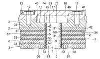
- FIG. 1 is a longitudinal sectional explanatory view of a preferred specific example of the seismic isolation support device of the present invention.
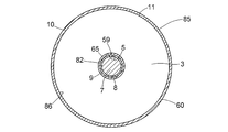
- 2 is a cross-sectional explanatory view taken along the line II-II in FIG.
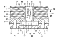
- FIG. 3 is an enlarged cross-sectional explanatory diagram of a main part of FIG.
- FIG. 4 is an enlarged cross-sectional explanatory view of the main part of FIG.
- FIG. 5 is a perspective explanatory view of the heat conductor shown in FIG.
- the seismic isolation support device 1 of this specific example has a cylindrical shape having a plurality of annular elastic layers 2 and a plurality of annular rigid layers 3 that are alternately stacked in the stacking direction V.
- Laminate 4 a cylindrical lead plug 7 serving as an attenuation body disposed in a cylindrical hollow portion 6 defined by the cylindrical inner peripheral surface 5 of the laminate 4, and a lead plug 7 in the hollow portion 6.
- the cylindrical heat conductor 9 is disposed between the cylindrical outer peripheral surface 8 and the inner peripheral surface 5 and has a thermal conductivity higher than that of the elastic layer 2, for example, at least 1 W / m ⁇ k.
- the outer peripheral protective layer 11 made of a rubber material having excellent weather resistance and covering the cylindrical outer peripheral surface 10 of the laminate 4, and the uppermost rigid layer 3 and rigid layer 3 of the rigid layer 3.
- An upper mounting plate 13 and a lower mounting plate 14 connected to each of the lowermost rigid layers 3 via bolts 12.
- a disk-shaped shear key 17 fitted in the circular recess 15 of the uppermost rigid layer 3 and the circular recess 16 of the upper mounting plate 13, and the circular recess of the lowermost rigid layer 3
- a disc-shaped shear key 20 fitted in a circular recess 19 of the lower mounting plate 14.
- Each of the elastic layers 2 is made of an elastic rubber plate having elasticity, and has a cylindrical inner peripheral surface 31, a cylindrical outer peripheral surface 32, an annular upper surface 33, and an annular lower surface 34. .
- the uppermost and lowermost rigid layers 3 are made of an elastic thick layer 2 and an annular thick steel plate that is thicker and more rigid than the rigid layers 3 between the uppermost and lowermost rigid layers 3.
- the uppermost rigid layer 3 defines an annular upper surface 41, an annular lower surface 42, a cylindrical inner peripheral surface 43, a cylindrical outer peripheral surface 44, a recess 15 and an inner periphery
- the inner circumferential surface 45 has a larger diameter than the surface 43 and an annular upper surface 46 that defines the recess 15 in cooperation with the inner circumferential surface 45, and the lowermost rigid layer 3 has an annular shape.
- Each of the rigid layers 3 between the uppermost and lowermost rigid layers 3 has a topmost portion, and an annular lower surface 56 that defines the recess 18 in cooperation with the inner peripheral surface 55.
- Each of the steel plates of the rigid layer 3 between the uppermost and lowermost rigid layers 3 and between the uppermost and lowermost rigid layers 3 is the heat of the elastic layer 2. It has a higher thermal conductivity than the conductivity (W / m ⁇ K).
- the uppermost rigid layer 3 is in close contact with the upper surface 33 of the elastic layer 2 adjacent in the stacking direction V on its lower surface 42, and the lowermost rigid layer 3 is adjacent in the stacking direction V on its upper surface 51.
- the lower surface 34 of the elastic layer 2 is in close contact with each other, and each of the rigid layers 3 between the uppermost and lowermost rigid layers 3 has an upper surface 57 on the lower surface 34 of the elastic layer 2 adjacent in the stacking direction V.
- the lower surface 58 is in close contact with the upper surface 33 of the elastic layer 2 adjacent in the stacking direction V.
- the laminated body 4 further includes a rubber coating layer 65 made of a rubber material equivalent to the elastic layer 2, and the rubber coating layer 65 includes the inner peripheral surface 43 and a plurality of layers.
- a cylindrical outer peripheral surface 66 in close contact with the inner peripheral surfaces 31 and 59 and the inner peripheral surface 53 and an inner peripheral surface 5 defining the hollow portion 6 are provided.
- the hollow portion 6 is defined by a circular lower surface 71 of the shear key 17 and a circular upper surface 72 of the shear key 20 in addition to the inner peripheral surface 5, and the lower surface 71 is a circular upper end surface 73 of the lead plug 7.
- the annular upper end surface 74 of the rubber coating layer 65 and the annular upper end surface 75 of the heat conductor 9 are in close contact with each other, and the upper surface 72 is a circular lower end surface 76 of the lead plug 7, rubber coating.
- the annular lower end surface 77 of the layer 65 and the annular lower end surface 78 of the heat conductor 9 are in close contact with each other.
- the thermal conductor 9 having a thickness of 0.3 to 1.0 mm and a thermal conductivity of at least 1 W / m ⁇ K is provided on the outer peripheral surface in addition to the upper end surface 75 and the lower end surface 78. 8 and an outer peripheral surface 82 in close contact with the inner peripheral surface 5.
- Each of the elastic layer 2 and each of the rigid layer 3 are the contact surfaces of the upper surfaces 33, 51 and 57 and the lower surfaces 34, 42 and 58 that are in contact with each other, and are firmly attached to each other by, for example, vulcanization adhesion or adhesive.
- the rubber coating layer 65 and each of the elastic layer 2 and the rigid layer 3 are vulcanized and bonded at the contact surfaces of the outer peripheral surface 66 and the inner peripheral surfaces 31, 43, 53, and 59 that contact each other.
- the rubber coating layer 65 and the heat conductor 9 are firmly bonded to each other by an adhesive, and the inner peripheral surface 5 and the outer peripheral surface 82 are in contact with each other and are vulcanized or bonded.
- the materials are firmly bonded to each other.
- the outer peripheral surface 10 includes a plurality of outer peripheral surfaces 32 and 60 and outer peripheral surfaces 44 and 54.
- the outer peripheral protective layer 11 and the elastic layer have a cylindrical inner peripheral surface 86 in addition to the cylindrical outer peripheral surface 85. 2 and the rigid layer 3 are firmly bonded to each other at their contact surfaces of the inner peripheral surface 86 and the outer peripheral surfaces 32, 44, 54 and 60 by vulcanization adhesion or adhesive.
- At least one of the rubber coating layer 65 and the outer peripheral protective layer 11 may be formed integrally with the elastic layer 2 by the protrusion of the elastic layer 2 during the pressure vulcanization molding of the laminate 4.
- the seismic isolation support device 1 is connected to the structure 91 by the upper mounting plate 13 and to the base 92 by the lower mounting plate 14 via bolts 93, and the structure 91 is laminated by the laminate 4 and the lead plug 7. It is used to support a load in the direction (vertical direction) V.
- the heat conductor 9 may be manufactured as follows (1), (2), or (3).
- a vulcanization accelerator for example, thiazole such as N-cyclohexyl-2-benzothiazyl sulfenamide, 2-mercaptobenzothiazole and dibenzothiazyl disulfide
- guanidines such as diphenyl guanidine
- vulcanization accelerators zinc white (ZnO)
- metal oxides such as magnesium oxide and fatty acids such as stearic acid, lauric acid and palmitic acid
- vulcanizing agents eg , Sulfur and sulfur-containing compounds, etc.
- process oils eg, paraffinic, naphthenic and aromatics
- anti-aging agents [N-isopropyl-N'-phenyl-P-phenylenediamine and N- (1,3, -Dimethylbutyl) -N'-phenyl-P-phenylenediamine, etc
- ⁇ (2) When using a novolak type phenolic resin as the polymer> Add at least one of the fillers and, if necessary, a curing agent, a release agent, and a curing accelerator to the novolac-type phenol resin powder and mix them together with a suitable amount of solvent in a mixer such as a Henschel mixer.
- a mixer such as a Henschel mixer.
- the mixture prepared by uniformly stirring and mixing is put into a kneader, the kneaded material kneaded while being cooled is cooled and solidified, and then the molding material obtained by pulverizing the cooled and solidified kneaded material to an appropriate size is uniformly placed in a mold.
- compression and molding are performed by applying pressure and heat, and processed into a long sheet having a uniform thickness and a predetermined width.
- This sheet is cut into a length that goes around the outer peripheral surface of the lead plug 7, and this is used as a sheet for the heat conductor 9.
- thermoplastic synthetic resin or a thermoplastic elastomer is used as the polymer>
- a mixture prepared by mixing thermoplastic synthetic resin or thermoplastic elastomer and at least one of the fillers with a mixer such as a Henschel mixer is extruded into a strand with a screw extruder, and the extruded strand mixture is cut.
- a pellet of the heat conductor composition is produced, and this pellet is supplied to an extrusion molding machine equipped with a T-die and extruded to be processed into a long sheet having a uniform thickness and a predetermined width. This sheet is cut into a length that goes around the outer peripheral surface of the lead plug 7, and this is used as a sheet for the heat conductor 9.
- the seismic isolation support device 1 including such a heat conductor 9 may be manufactured as follows.
- Vulcanization accelerators, vulcanization accelerators, vulcanizing agents, process oils, and anti-aging agents are blended with crosslinked rubber, and a rubber composition is prepared through a kneading and kneading process, and then a calender roll machine is used. Then, the rubber composition is rolled to cut out an unvulcanized rubber plate for the elastic layer 2 from an unvulcanized rubber sheet having a uniform thickness and a predetermined width.
- ⁇ Preparation of laminated body 4 and seismic isolation support device 1> The sheet for the heat conductor 9 obtained in the above (1), (2) or (3) is wound around the outer periphery of the columnar body provided in the mold in a cylindrical shape, and the sheet is fixed. If necessary, an unvulcanized rubber sheet having a thickness of 0.3 to 0.5 mm for the rubber coating layer 65 is wound around the outer peripheral surface of the cylindrical sheet for the heat conductor 9 in a cylindrical shape. The cylindrical rubber sheet is fixed, and a thick steel plate for the lowermost rigid layer 3 is disposed on the outer peripheral surface of the cylindrical rubber sheet for the rubber coating layer 65 with the recess 18 facing downward.
- the adhesive is preferably an adhesive two-component coating method in which an undercoat adhesive is applied to the upper surface 51 as a primer and then an overcoat adhesive is further applied.
- an unvulcanized rubber plate for the elastic layer 2 is provided on the outer peripheral surface of the cylindrical sheet for the heat conductor 9 through the through hole defined by the inner peripheral surface 31 as necessary. Is placed on the upper surface 51 of the thick steel plate for the lowermost rigid layer 3 that is fitted into the outer peripheral surface of the cylindrical rubber sheet for the rubber coating layer 65 and is coated with an adhesive.
- a thin steel plate for each rigid layer 3 and an unvulcanized rubber plate for the elastic layer 2 between the uppermost and lowermost rigid layers 3 coated with an adhesive on the lower surface 58 are alternately provided in the mold.
- a plurality of the cylindrical rubber sheets for the rubber coating layer 65 are provided around the cylindrical sheet. Stacking, finally, around the cylindrical sheet for the heat conductor 9 fixed on the outer peripheral surface of the cylinder provided in the mold The lowermost rigid layer 3 and the uppermost layer and the lowermost rigid layer 3 are alternately stacked around a cylindrical rubber sheet for the rubber coating layer 65.
- Heat conductor 9 provided in the mold so that the thick steel plate for the uppermost rigid layer 3 is further placed on the thin steel plate for use and the unvulcanized rubber plate for the elastic layer 2.
- the unvulcanized laminate 4 provided with a cylindrical sheet for the heat conductor 9, and a cylindrical rubber sheet for the rubber coating layer 65 provided as necessary, On the outer peripheral surface 10 of the unvulcanized laminate 4, a thin unvulcanized rubber sheet having excellent weather resistance for the outer peripheral protective layer 11 is formed into a cylindrical shape.
- the unvulcanized laminate 4 is heated and pressurized to form a cylindrical rubber sheet for the heat conductor 9, an unvulcanized rubber plate for the elastic layer 2, and an unvulcanized layer for the outer peripheral protective layer 11.
- the cylindrical rubber sheet and the cylindrical rubber sheet for the rubber coating layer 65 provided as necessary are vulcanized and vulcanized and bonded together to form the heat conductor 9, the outer peripheral protective layer 11, and the rubber coating.
- the laminated body 4 provided with the layer 65 is produced.
- the shear key 17 is inserted into each of the recesses 15 and 18.
- the upper mounting plate 13 and the lower mounting plate 14 are connected to the uppermost rigid layer 3 and the lowermost rigid layer 3 via the bolts 12, respectively, to produce the seismic isolation support device 1. .
- the rubber sheets for the rubber coating layer 65 and the outer peripheral protective layer 11 are not rubbed and unvulcanized for the elastic layer 2 by heating and pressing the laminate 4.
- the rubber covering layer 65 and the outer peripheral protective layer 11 may be formed by bulging the inner peripheral side and the outer peripheral side of the rubber plate.
- Example 1 100 parts by weight of natural rubber (NR) as a polymer, 5 parts by weight of carbon black as a filler, and pitch-based carbon fiber (GRANOC milled fiber “XN-100 (trade name)” manufactured by Nippon Graphite Fiber Co., Ltd.), average length
- An unvulcanized sheet for the heat conductor 9 having a thickness of 0.5 mm is prepared from 20 parts by mass of 50 ⁇ m and an average fiber diameter of 7 ⁇ m by the method of (1) above, while an unvulcanized sheet for the elastic layer 2 is prepared.
- a circular rubber plate having a diameter of 1000 mm is cut out from the rubber sheet, and a through hole defined by the inner peripheral surface 31 having a diameter of 202 mm is cut out at the center of the rubber plate to produce an unvulcanized rubber plate for the elastic layer 2. did.
- a rubber comprising such an unvulcanized sheet for the heat conductor 9, 32 unvulcanized rubber plates for the elastic layer 2, and a rubber composition similar to the unvulcanized rubber sheet for the elastic layer 2.
- the seismic isolation support device 1 was produced from an unvulcanized rubber sheet having a thickness of 0.5 mm for the covering layer 65 and an unvulcanized rubber sheet having a thickness of 5 mm for the outer peripheral protective layer 11.
- the thermal conductor 9 in the manufactured seismic isolation support device 1 exhibited a thermal conductivity of 1 W / m ⁇ K.
- Example 2 As a filler, 30 parts by mass of the pitch-based carbon fiber of Example 1 and 30 parts by mass of scaly graphite (1) (“PS-99 (trade name) manufactured by Nishimura Graphite Co., Ltd., average particle diameter: 7 ⁇ m)” were used. Except for the above, the seismic isolation support device 1 was produced in the same manner as in Example 1. The thermal conductor 9 in the manufactured seismic isolation support device 1 exhibited a thermal conductivity of 10 W / m ⁇ K.
- Example 3 100 parts by mass of butyl rubber (polycerbutyl) (IIR) as a polymer, 50 parts by mass of carbon black of Example 1 as a filler, 15 parts by mass of pitch-based carbon fibers, and scaly graphite (2) (manufactured by TIMCAL Except for using 75 parts by mass of KS15 (trade name), average particle diameter 8 ⁇ m), the base isolation support device 1 was manufactured in the same manner as in Example 1. The heat conductor 9 in the base isolation support device 1 thus manufactured was The thermal conductivity was 14 W / m ⁇ K.
- Example 4 100 parts by mass of ethylene propylene rubber (EPDM) as a polymer, 40 parts by mass of carbon black as a filler, and 96 parts by mass of hexagonal boron nitride (BN) (manufactured by Denki Kagaku Kogyo Co., Ltd., average particle size: 15 ⁇ m) were used. Except for the above, the seismic isolation support device 1 was produced in the same manner as in Example 1. The thermal conductor 9 in the manufactured seismic isolation support device 1 exhibited a thermal conductivity of 5 W / m ⁇ K.
- EPDM ethylene propylene rubber
- carbon black as a filler
- BN hexagonal boron nitride
- Example 5 The method of (3) above from 100 parts by mass of polyacetal resin (POM) as a polymer, 150 parts by mass of pitch-based carbon fiber as filler and 30 parts by mass of aluminum oxide (Al 2 O 3 ) (manufactured by Showa Denko KK)
- the seismic isolation support device 1 was produced in the same manner as in Example 1 except that a sheet for the unvulcanized 0.5 mm thick heat conductor 9 was produced.
- the thermal conductor 9 in the manufactured seismic isolation support device 1 exhibited a thermal conductivity of 2 W / m ⁇ K.
- Example 6 In the same manner as in Example 5, the thickness of the polyamide resin (PA6) 100 parts by mass as a polymer and scaly graphite (3) (manufactured by Nippon Graphite Co., Ltd., average particle size 130 ⁇ m) 132 parts by mass was used.
- a seismic isolation support device 1 was produced in the same manner as in Example 1 except that a sheet for a 5 mm unvulcanized heat conductor 9 was produced.
- the thermal conductor 9 in the manufactured seismic isolation support device 1 exhibited a thermal conductivity of 20 W / m ⁇ K.
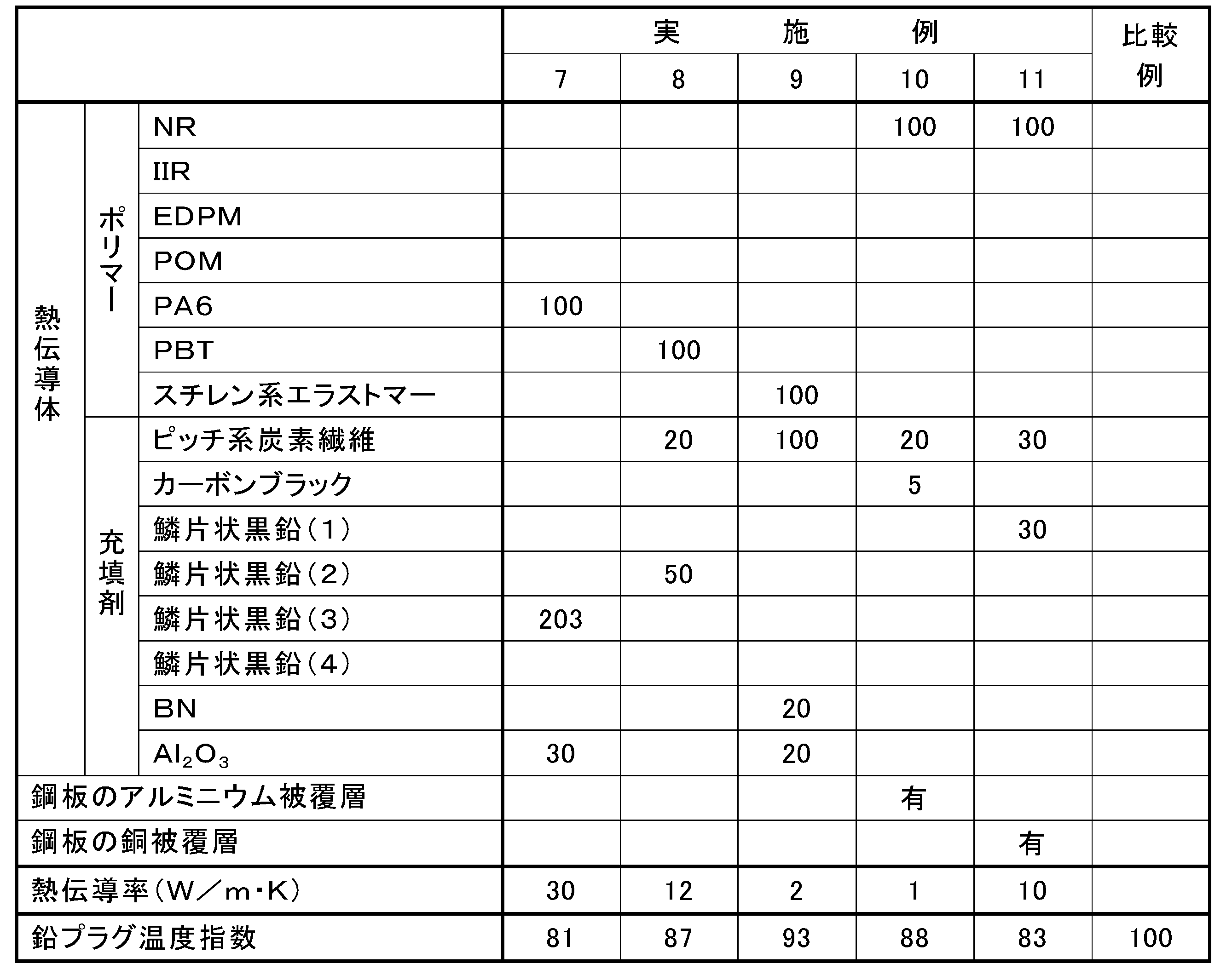
- Example 7 For unvulcanized heat conductor 9 having a thickness of 0.5 mm in the same manner as in Example 5 from 100 parts by mass of polyamide resin (PA6) as a polymer and 203 parts by mass of flaky graphite (3) as a filler
- the seismic isolation support device 1 was produced in the same manner as in Example 1 except that the sheet was produced.
- the thermal conductor 9 in the manufactured seismic isolation support device 1 exhibited a thermal conductivity of 30 W / m ⁇ K.
- Example 8 Example 5 from 100 parts by mass of polybutylene terephthalate resin (PBT) as a polymer, 50 parts by mass of flake graphite (2) of Example 3 as a filler and 20 parts by mass of pitch-based carbon fiber of Example 1 Similarly, the seismic isolation support device 1 was produced in the same manner as in Example 1 except that a sheet for the unvulcanized heat conductor 9 having a thickness of 0.5 mm was produced. The thermal conductor 9 in the manufactured seismic isolation support device 1 exhibited a thermal conductivity of 12 W / m ⁇ K.
- PBT polybutylene terephthalate resin
- Example 9 100 parts by mass of a low-hardness styrene-based thermoplastic elastomer as a polymer, 100 parts by mass of pitch-based carbon fiber of Example 1 as a filler, 20 parts by mass of hexagonal boron nitride of Example 4, and aluminum oxide of Example 5 From 20 parts by mass, a sheet for an unvulcanized thermal conductor 9 having a thickness of 0.5 mm was produced in the same manner as in Example 5, and the outside was produced in the same manner as in Example 1 to produce a seismic isolation support device 1. .
- the thermal conductor 9 in the manufactured seismic isolation support device 1 exhibited a thermal conductivity of 2 W / m ⁇ K.
- Example 10 An unvulcanized sheet for the heat conductor 9 similar to that in Example 1 and an unvulcanized rubber plate for the elastic layer 2 and an aluminum coating layer having a thickness of 60 ⁇ m were formed on the entire surface by hot-dip aluminum plating.
- the seismic isolation support device 1 was produced in the same manner as in Example 1 from the thin and thick steel plates for the rigid layer 3.
- the thermal conductor 9 in the manufactured seismic isolation support device 1 exhibited a thermal conductivity of 1 W / m ⁇ K.
- Example 11 An unvulcanized sheet for the heat conductor 9 similar to that in Example 2 and an unvulcanized rubber plate for the elastic layer 2 and a copper coating layer having a thickness of 30 ⁇ m are formed on the entire surface by electroless copper plating.
- the seismic isolation support device 1 was produced in the same manner as in Example 1 from the thin and thick steel plates for the rigid layer 3.
- the thermal conductor 9 in the manufactured seismic isolation support device 1 exhibited a thermal conductivity of 10 W / m ⁇ K.
- the seismic isolation support device 1 was produced in the same manner as each example without using a sheet for the heat conductor 9.
- Example 1 the seismic isolation support device 1 obtained in Example 1 to Example 11 and the comparative example was tested for the temperature rise of the lead plug 7 with the horizontal displacement H repeatedly received many times during a huge earthquake.
- the test results are shown in Tables 1 and 2.
- the lead plug temperature index in Tables 1 to 3 is the temperature after 50 cycles of vibration of the lead plugs 7 of Examples 1 to 11 and the temperature value of the lead plug 7 of the comparative example after 50 cycles of vibration.
- the ratio is expressed as 100.
- the temperature rise generated in the lead plug 7 can be released to the rigid layer 3 through the heat conductor 9, so that the lead during an earthquake or the like An excessive temperature rise of the plug 7 can be prevented.
- Seismic isolation support device Elastic layer 3 Rigid layer 4 Laminate 5 Inner peripheral surface 6 Hollow part 7 Lead plug 8, 10 Outer surface 9 Thermal conductor
Landscapes
- Engineering & Computer Science (AREA)
- General Engineering & Computer Science (AREA)
- Architecture (AREA)
- Mechanical Engineering (AREA)
- Business, Economics & Management (AREA)
- Emergency Management (AREA)
- Environmental & Geological Engineering (AREA)
- Physics & Mathematics (AREA)
- Acoustics & Sound (AREA)
- Aviation & Aerospace Engineering (AREA)
- Civil Engineering (AREA)
- Structural Engineering (AREA)
- Chemical & Material Sciences (AREA)
- Health & Medical Sciences (AREA)
- Chemical Kinetics & Catalysis (AREA)
- Medicinal Chemistry (AREA)
- Polymers & Plastics (AREA)
- Organic Chemistry (AREA)
- Vibration Prevention Devices (AREA)
- Springs (AREA)
- Buildings Adapted To Withstand Abnormal External Influences (AREA)
Abstract
Description
架橋ゴムに、充填剤のうちの少なくとも一つと、必要に応じて加硫促進剤(例えば、N-シクロヘキシル-2-ベンゾチアジル・スルフェンアミド、2-メルカプトベンゾチアゾール及びジベンゾチアジルジサルファイド等のチアゾール系並びにジフェニルグアジニン等のグアジニン系)、加硫促進助剤(亜鉛華(ZnO))及び酸化マグネシウム等の金属酸化物及びステアリン酸、ラウリン酸及びパルミチン酸等の脂肪酸)、加硫剤(例えば、硫黄及び硫黄含有化合物等)、プロセスオイル(例えば、パラフィン系、ナフテン系及び芳香族系等)及び老化防止剤〔N-イソプロピル-N′-フェニル-P-フェニレンジアミン及びN-(1、3-ジメチルブチル)-N′-フェニル-P-フェニレンジアミン等〕とを配合した後、素練り及び混練り工程を経て作製した熱伝導体組成物を、ついで、カレンダーロール機を用いて均一な厚さ、所定の幅の長いシートに圧延加工する。このシートを鉛プラグの外周面8を一周する長さに切断して、これを熱伝導体9用の未加硫のシートとする。
ノボラック型フェノール樹脂粉末に充填剤のうちの少なくとも一つと必要に応じて、硬化剤、離型剤、硬化促進剤とを加えて混合し、これらを適量の溶剤とともにヘンシェルミキサー等の混合機にて均一に撹拌混合して作製した混合物を混練機に投入し、加熱しながら混練した混練物を冷却固化した後、冷却固化した混練物を適当な大きさに粉砕した成形材料を金型に均一に入れ、圧力と熱をかけて圧縮成形し、均一な厚さと所定の幅を有する長いシートに加工する。このシートを鉛プラグ7の外周面を一周する長さに切断して、これを熱伝導体9用のシートとする。
熱可塑性合成樹脂又は熱可塑性エラストマーと充填剤のうちの少なくとも一つとをヘンシェルミキサー等の混合機で混合して作製した混合物をスクリュー式押出機でストランド状に押し出し、押し出したストランド状の混合物を切断して熱伝導体組成物のペレットを作製し、このペレットを、Tダイを備えた押出成形機に供給し、押出成形して均一な厚さと所定の幅を有する長いシートに加工する。このシートを鉛プラグ7の外周面を一周する長さに切断して、これを熱伝導体9用のシートとする。
架橋ゴムに加硫促進剤、加硫促進助剤、加硫剤、プロセスオイル、老化防止剤を配合し、素練り及び混練り工程を経てゴム組成物を作製し、ついで、カレンダーロール機を用いてゴム組成物を圧延加工して均一な厚さ、所定の幅の長い未加硫のゴムシートから弾性層2用の未加硫のゴム板を切り抜く。
薄肉の冷間圧延鋼板(SPCC)からプレス加工により最上部及び最下部の剛性層3間の剛性層3用の円環状の薄肉の鋼板と、厚肉の冷間圧延鋼板(SPCC)から同じくプレス加工により最上部及び最下部の剛性層3用の円環状の厚肉の鋼板とを作製する。
金型内に設けられた円柱体の外周面に上記(1)、(2)又は(3)で得られた熱伝導体9用のシートを円筒状に一周巻き付けて当該シートを固定すると共に当該熱伝導体9用の円筒状のシートの外周面に、必要に応じて、ゴム被覆層65用の0.3~0.5mmの厚さの未加硫のゴムシートを円筒状に一周巻き付け、この円筒状のゴムシートを固定すると共に当該ゴム被覆層65用の円筒状のゴムシートの外周面に、最下部の剛性層3用の厚肉の鋼板を凹所18を下向きにして内周面53で規定される貫通孔を介して嵌挿し、当該厚肉の鋼板の上面51に接着剤を塗布する。接着剤としては、上面51にプライマーとして下塗り接着剤を塗布した後、さらに上塗り接着剤を塗布する接着剤二液塗工式が好ましい。ついで、弾性層2用の未加硫のゴム板を内周面31で規定された貫通孔を介して熱伝導体9用の円筒状のシートの外周面に、必要に応じて設けられる場合には、ゴム被覆層65用の円筒状のゴムシートの外周面に嵌挿して接着剤が塗布された最下部の剛性層3用の厚板の鋼板の上面51に載置し、以下、上面57及び下面58に接着剤を塗布した最上部及び最下部剛性層3間の各剛性層3用の薄板の鋼板と弾性層2用の未加硫のゴム板とを交互に金型内に設けられた円柱体の外周面に固定された熱伝導体9用の円筒状のシートの周りに、必要に応じて設けられる場合には、ゴム被覆層65用の円筒状のゴムシートの周りに複数個積み重ね、最後に、金型内に設けられた円柱体の外周面に固定された熱伝導体9用の円筒状のシートの周りに、必要に応じて設けられる場合には、ゴム被覆層65用の円筒状のゴムシートの周りに交互に積み重ねられた最下部の剛性層3、最上部及び最下部の剛性層3間の各剛性層3用の薄肉の鋼板及び弾性層2用の未加硫のゴム板に最上部の剛性層3用の厚肉の鋼板が更に載置されるように、金型内に設けられた熱伝導体9用の円筒状のシートに、必要に応じて設けられる場合には、ゴム被覆層65用の円筒状のゴムシートに、下面42に接着剤を塗付した最上部の剛性層3用の厚肉の鋼板を嵌挿して、熱伝導体9用の円筒状のシート、必要に応じて設けられたゴム被覆層65用の円筒状のゴムシートを備えた未加硫の積層体4を作製し、この未加硫の積層体4の外周面10に、外周保護層11用の耐候性に優れた薄肉の未加硫のゴムシートを円筒状に巻き付け、この未加硫の積層体4を加熱加圧して、熱伝導体9用の円筒状のゴムシート、弾性層2用の未加硫のゴム板並びに外周保護層11用の未加硫の円筒状のゴムシート及び必要に応じて設けられたゴム被覆層65用の円筒状のゴムシートの加硫化を行うと共に相互を加硫接着して熱伝導体9、外周保護層11及びゴム被覆層65を備えた積層体4を作製する。
架橋ゴムとして天然ゴムと、カーボンブラックと、亜鉛華(ZnO)と、ステアリン酸と、老化防止剤と、プロセスオイルとを汎用の混練機に投入し、混練りした。ついで、これに加硫促進剤及び加硫剤を投入し、オープンロールを使用して混練りし、混練りしたゴム組成物を圧延加工して未加硫の厚さ5mmのゴムシートを作製した。
最上部及び最下部の剛性層3間の剛性層3として、外径1000mm、厚さ3.9mmを有すると共に中央部に直径202mmの内周面59で規定される貫通孔を有する冷間圧延鋼板(SPCC)からなる円板状の薄肉の鋼板と、最上部及び最下部の剛性層3として、外径1000mm、厚さ40mmを有すると共に中央部に直径240mmの凹所15及び18の夫々と、凹所15及び18の夫々の中央部に直径202mmの内周面43及び53の夫々で規定される貫通孔を夫々有する夫々冷間圧延鋼板(SPCC)からなる二枚の厚肉の鋼板を準備した。
ポリマーとしての天然ゴム(NR)100質量部と、充填剤としてのカーボンブラック5質量部及びピッチ系炭素繊維(日本グラファイトファイバー社製のGRANOCミルドファイバー「XN-100(商品名)」、平均長さ50μm、平均繊維径7μm)20質量部とから上記(1)の方法をもって厚さ0.5mmの熱伝導体9用の未加硫のシートを作製する一方、弾性層2用の未加硫のゴムシートから、直径1000mmの円形のゴム板を切り抜くと共にこのゴム板の中央部に直径202mmの内周面31で規定される貫通孔を切り抜き、弾性層2用の未加硫のゴム板を作製した。
充填剤として実施例1のピッチ系炭素繊維30質量部と、鱗片状黒鉛(1)(西村黒鉛社製の「PS-99(商品名)」、平均粒径7μm)30質量部とを用いた以外は実施例1と同様の方法で免震支持装置1を作製した。作製した免震支持装置1における熱伝導体9は、10W/m・Kの熱伝導率を示した。
ポリマーとしてのブチルゴム(ポリサーブチル)(IIR)100質量部と、充填剤としての実施例1のカーボンブラック50質量部、ピッチ系炭素繊維15質量部及び鱗片状黒鉛(2)(TIMCAL社製の「KS15(商品名)、平均粒子径8μm)75質量部とを用いた以外は実施例1と同様の方法で免震支持装置1を作製した。作製した免震支持装置1における熱伝導体9は、14W/m・Kの熱伝導率を示した。
ポリマーとしてのエチレンプロピレンゴム(EPDM)100質量部と、充填剤としてのカーボンブラック40質量部、六方晶窒化ホウ素(BN)(電気化学工業社製、平均粒径15μm)96質量部とを用いた以外は実施例1と同様の方法で免震支持装置1を作製した。作製した免震支持装置1における熱伝導体9は、5W/m・Kの熱伝導率を示した。
ポリマーとしてのポリアセタール樹脂(POM)100質量部と、充填剤としてのピッチ系炭素繊維150質量部及び酸化アルミニウム(Al2O3)(昭和電工社製)30質量部とから上記(3)の方法をもって未加硫の厚さ0.5mmの熱伝導体9用のシートを作製した以外は、実施例1と同様の方法で免震支持装置1を作製した。作製した免震支持装置1における熱伝導体9は、2W/m・Kの熱伝導率を示した。
ポリマーとしてのポリアミド樹脂(PA6)100質量部と、充填剤としての鱗片状黒鉛(3)(日本黒鉛社製、平均粒径130μm)132質量部とから実施例5と同様にして厚さ0.5mmの未加硫の熱伝導体9用のシートを作製した以外は、実施例1と同様にして免震支持装置1を作製した。作製した免震支持装置1における熱伝導体9は、20W/m・Kの熱伝導率を示した。
ポリマーとしてのポリアミド樹脂(PA6)100質量部と、充填剤としての鱗片状黒鉛(3)203質量部とから実施例5と同様にして厚さ0.5mmの未加硫の熱伝導体9用のシートを作製した以外は、実施例1と同様にして免震支持装置1を作製した。作製した免震支持装置1における熱伝導体9は、30W/m・Kの熱伝導率を示した。
ポリマーとしてのポリブチレンテレフタレート樹脂(PBT)100質量部と、充填剤としての実施例3の鱗片状黒鉛(2)50質量部及び実施例1のピッチ系炭素繊維20質量部とから実施例5と同様にして厚さ0.5mmの未加硫の熱伝導体9用のシートを作製した以外は、実施例1と同様にして免震支持装置1を作製した。作製した免震支持装置1における熱伝導体9は、12W/m・Kの熱伝導率を示した。
ポリマーとしての低硬度のスチレン系熱可塑性エラストマー100質量部と、充填剤としての実施例1のピッチ系炭素繊維100質量部、実施例4の六方晶窒化ホウ素20質量部及び実施例5の酸化アルミニウム20質量部とから実施例5と同様にして厚さ0.5mmの未加硫の熱伝導体9用のシートを作製し対外は、実施例1と同様にして免震支持装置1を作製した。作製した免震支持装置1における熱伝導体9は、2W/m・Kの熱伝導率を示した。
実施例1と同様の熱伝導体9用の未加硫のシート及び弾性層2用の未加硫のゴム板と、溶融アルミニウムメッキにより表面に厚さ60μmのアルミニウム被覆層が全面に形成された剛性層3用の薄肉及び厚肉の鋼板とから実施例1と同様にして免震支持装置1を作製した。作製した免震支持装置1における熱伝導体9は、1W/m・Kの熱伝導率を示した。
実施例2と同様の熱伝導体9用の未加硫のシート及び弾性層2用の未加硫のゴム板と、無電解銅メッキにより表面に厚さ30μmの銅被覆層が全面に形成された剛性層3用の薄肉及び厚肉の鋼板とから実施例1と同様にして免震支持装置1を作製した。作製した免震支持装置1における熱伝導体9は、10W/m・Kの熱伝導率を示した。
比較例として、熱伝導体9用のシートを用いないで各実施例と同様にして免震支持装置1を作製した。
面圧 15N/mm2(706.9kN)
剪断歪み(γ) 250%(120mm)
振動数 0.3Hz
最大速度 22.6kine
加振波数 50サイクル
<試験方法>
300トンの二軸試験機を用いて、上記試験条件に示す正弦波形の加振を50サイクル行い、鉛プラグ7に取り付けた熱電対センサにより、50サイクル加振後の鉛プラグ7の温度を測定した。

2 弾性層
3 剛性層
4 積層体
5 内周面
6 中空部
7 鉛プラグ
8、10 外周面
9 熱伝導体
Claims (10)
- 複数の弾性層及び剛性層を有する積層体と、この積層体の内周面で規定された柱状の中空部に配されている柱状の減衰体と、減衰体の外周面及び積層体の内周面間に配されていると共に弾性層の熱伝導率よりも高い熱伝導率を有した熱伝導体とを具備しており、この熱伝導体は、減衰体の筒状の外周面に接触した内周面と、積層体の内周面に接触した外周面とを有しており、剛性層の夫々は、弾性層の熱伝導率(W/m・K)よりも高い熱伝導率を有する環状の鋼板を具備している免震支持装置。
- 熱伝導体、熱伝導体の内周面及び熱伝導体の外周面の夫々は、筒状である請求項1に記載の免震支持装置。
- 熱伝導体は、少なくともポリマーと、弾性層の熱伝導率よりも高い熱伝導率を有した充填剤とを含んでいる請求項1又は2に記載の免震支持装置。
- ポリマーは、熱硬化性ポリマー及び熱可塑性ポリマーのうちの少なくとも一つを含んでいる請求項3に記載の免震支持装置。
- 熱硬化性ポリマーは、架橋ゴム、エポキシ樹脂、ポリイミド樹脂、ビスマレイミド樹脂、フェノール樹脂、不飽和ポリエステル樹脂、熱硬化型ポリフェニレンエーテル樹脂及び熱硬化型変性ポリフェニレンエーテル樹脂のうちの少なくとも一つを含んでいる請求項4に記載の免震支持装置。
- 熱可塑性ポリマーは、熱可塑性合成樹脂及び熱可塑性エラストマーのうちの少なくとも一つを含んでいる請求項4又は5に記載の免震支持装置。
- 充填剤は、カーボン系充填剤、金属系充填剤及びセラミック系充填剤のうちの少なくとも一つを含んでいる請求項3から6のいずれか一項に記載の免震支持装置。
- 熱伝導体は、少なくとも1W/m・Kの熱伝導率を有している請求項1から7のいずれか一項に記載の免震支持装置。
- 熱伝導体は、その外周面で、積層体の内周面となる鋼板の面に接触している請求項1から8のいずれか一項に記載の免震支持装置。
- 複数の剛性層の夫々は、鋼板を被覆していると共に鋼板の熱伝導率よりも高い熱伝導率を有する被覆層を具備しており、熱伝導体は、その外周面で、積層体の内周面となる被覆層の面に接触している請求項1から8のいずれか一項に記載の免震支持装置。
Priority Applications (4)
| Application Number | Priority Date | Filing Date | Title |
|---|---|---|---|
| US15/557,231 US20180051764A1 (en) | 2015-03-20 | 2016-03-03 | Seismic base isolation support apparatus |
| CN201680016770.2A CN107429783A (zh) | 2015-03-20 | 2016-03-03 | 隔震支撑装置 |
| KR1020177026229A KR20170128337A (ko) | 2015-03-20 | 2016-03-03 | 면진 지지 장치 |
| EP16767952.1A EP3273090A4 (en) | 2015-03-20 | 2016-03-03 | Seismic base isolation support device |
Applications Claiming Priority (2)
| Application Number | Priority Date | Filing Date | Title |
|---|---|---|---|
| JP2015-058680 | 2015-03-20 | ||
| JP2015058680A JP6540134B2 (ja) | 2015-03-20 | 2015-03-20 | 免震支持装置 |
Publications (1)
| Publication Number | Publication Date |
|---|---|
| WO2016152041A1 true WO2016152041A1 (ja) | 2016-09-29 |
Family
ID=56977191
Family Applications (1)
| Application Number | Title | Priority Date | Filing Date |
|---|---|---|---|
| PCT/JP2016/001162 Ceased WO2016152041A1 (ja) | 2015-03-20 | 2016-03-03 | 免震支持装置 |
Country Status (7)
| Country | Link |
|---|---|
| US (1) | US20180051764A1 (ja) |
| EP (1) | EP3273090A4 (ja) |
| JP (1) | JP6540134B2 (ja) |
| KR (1) | KR20170128337A (ja) |
| CN (1) | CN107429783A (ja) |
| TW (1) | TWI693325B (ja) |
| WO (1) | WO2016152041A1 (ja) |
Cited By (2)
| Publication number | Priority date | Publication date | Assignee | Title |
|---|---|---|---|---|
| CN109853722A (zh) * | 2019-03-20 | 2019-06-07 | 华北水利水电大学 | 一种减震抗震型钢结构建筑 |
| CN109898564A (zh) * | 2019-04-14 | 2019-06-18 | 山东天智信息科技有限公司 | 一种建筑多维隔震装置 |
Families Citing this family (8)
| Publication number | Priority date | Publication date | Assignee | Title |
|---|---|---|---|---|
| US9869084B2 (en) * | 2014-10-14 | 2018-01-16 | Emeh, Inc. | Stair expansion joint system with freedom of movement between landings |
| JP2017194098A (ja) * | 2016-04-19 | 2017-10-26 | オイレス工業株式会社 | 免震装置 |
| US10927920B2 (en) * | 2017-10-04 | 2021-02-23 | Illinois Tool Works, Inc | Passive damping system for mass flow controller |
| EP3540151B1 (en) * | 2018-03-15 | 2025-02-12 | Soletanche Freyssinet | Enhanced seismic isolation lead rubber bearings |
| KR102634353B1 (ko) * | 2018-11-26 | 2024-02-08 | 현대자동차주식회사 | 차량용 방진고무 조성물 |
| CN110154732B (zh) * | 2019-06-11 | 2020-03-17 | 湖南机电职业技术学院 | 一种新型汽车动力总成悬置装置 |
| GB202009430D0 (en) * | 2020-06-19 | 2020-08-05 | Ocado Innovation Ltd | A grid framework structure |
| US12201227B2 (en) * | 2022-06-03 | 2025-01-21 | Apple Inc. | Product display stand with reduced movement |
Citations (5)
| Publication number | Priority date | Publication date | Assignee | Title |
|---|---|---|---|---|
| JPH1148396A (ja) * | 1997-08-06 | 1999-02-23 | Nitta Ind Corp | 積層体の予熱方法 |
| JP2003191253A (ja) * | 2001-12-28 | 2003-07-08 | Toyo Tire & Rubber Co Ltd | 積層ゴムの製造方法 |
| JP2003214493A (ja) * | 2001-10-22 | 2003-07-30 | Toyo Tire & Rubber Co Ltd | 積層ゴム支承装置及びその製造方法 |
| JP2011141002A (ja) * | 2010-01-08 | 2011-07-21 | Bridgestone Corp | 免震装置 |
| JP2012132504A (ja) * | 2010-12-21 | 2012-07-12 | Bridgestone Corp | 免震装置 |
Family Cites Families (9)
| Publication number | Priority date | Publication date | Assignee | Title |
|---|---|---|---|---|
| NZ201015A (en) * | 1982-06-18 | 1986-05-09 | New Zealand Dev Finance | Building support:cyclic shear energy absorber |
| JP2883219B2 (ja) * | 1990-10-17 | 1999-04-19 | オイレス工業株式会社 | 免震支持装置 |
| JPH08326840A (ja) * | 1995-05-26 | 1996-12-10 | Bridgestone Corp | 免震構造体 |
| US5765322A (en) * | 1995-09-29 | 1998-06-16 | Bridgestone Corporation | Seismic isolation apparatus |
| JP3749761B2 (ja) * | 1995-10-02 | 2006-03-01 | 株式会社エコ・トゥエンティーワン | 空調換気装置 |
| KR101256771B1 (ko) * | 2009-12-25 | 2013-04-25 | 요코하마 고무 가부시키가이샤 | 고무 지승장치 |
| JP5884612B2 (ja) * | 2012-04-10 | 2016-03-15 | 住友電気工業株式会社 | 空気ばね |
| TWI426168B (zh) * | 2012-06-14 | 2014-02-11 | Chong-Shien Tsai | Can prevent the temperature rise of the support pad |
| JP5541329B2 (ja) * | 2012-09-03 | 2014-07-09 | オイレス工業株式会社 | 免震装置 |
-
2015
- 2015-03-20 JP JP2015058680A patent/JP6540134B2/ja active Active
-
2016
- 2016-03-03 WO PCT/JP2016/001162 patent/WO2016152041A1/ja not_active Ceased
- 2016-03-03 EP EP16767952.1A patent/EP3273090A4/en not_active Withdrawn
- 2016-03-03 KR KR1020177026229A patent/KR20170128337A/ko not_active Withdrawn
- 2016-03-03 CN CN201680016770.2A patent/CN107429783A/zh not_active Withdrawn
- 2016-03-03 US US15/557,231 patent/US20180051764A1/en not_active Abandoned
- 2016-03-16 TW TW105108132A patent/TWI693325B/zh active
Patent Citations (5)
| Publication number | Priority date | Publication date | Assignee | Title |
|---|---|---|---|---|
| JPH1148396A (ja) * | 1997-08-06 | 1999-02-23 | Nitta Ind Corp | 積層体の予熱方法 |
| JP2003214493A (ja) * | 2001-10-22 | 2003-07-30 | Toyo Tire & Rubber Co Ltd | 積層ゴム支承装置及びその製造方法 |
| JP2003191253A (ja) * | 2001-12-28 | 2003-07-08 | Toyo Tire & Rubber Co Ltd | 積層ゴムの製造方法 |
| JP2011141002A (ja) * | 2010-01-08 | 2011-07-21 | Bridgestone Corp | 免震装置 |
| JP2012132504A (ja) * | 2010-12-21 | 2012-07-12 | Bridgestone Corp | 免震装置 |
Non-Patent Citations (1)
| Title |
|---|
| See also references of EP3273090A4 * |
Cited By (2)
| Publication number | Priority date | Publication date | Assignee | Title |
|---|---|---|---|---|
| CN109853722A (zh) * | 2019-03-20 | 2019-06-07 | 华北水利水电大学 | 一种减震抗震型钢结构建筑 |
| CN109898564A (zh) * | 2019-04-14 | 2019-06-18 | 山东天智信息科技有限公司 | 一种建筑多维隔震装置 |
Also Published As
| Publication number | Publication date |
|---|---|
| EP3273090A1 (en) | 2018-01-24 |
| US20180051764A1 (en) | 2018-02-22 |
| TW201641790A (zh) | 2016-12-01 |
| EP3273090A4 (en) | 2018-11-14 |
| JP6540134B2 (ja) | 2019-07-10 |
| CN107429783A (zh) | 2017-12-01 |
| TWI693325B (zh) | 2020-05-11 |
| JP2016176577A (ja) | 2016-10-06 |
| KR20170128337A (ko) | 2017-11-22 |
Similar Documents
| Publication | Publication Date | Title |
|---|---|---|
| JP6458516B2 (ja) | 免震支持装置 | |
| WO2016152041A1 (ja) | 免震支持装置 | |
| Li et al. | Electrically and thermally conductive underwater acoustically absorptive graphene/rubber nanocomposites for multifunctional applications | |
| JP6082777B2 (ja) | 熱伝導性シート及びその製造方法 | |
| US9487690B2 (en) | Anisotropic heat conductive composition and molded product thereof | |
| KR101715988B1 (ko) | 열전도성 시트 및 그 제조 방법 | |
| US20210254910A1 (en) | Thermal interface materials | |
| US20110014466A1 (en) | Composite materials comprising core-shell nano-fibrils | |
| US20140239738A1 (en) | Transmission sheet, transmission unit, and non-contact power transmission system including the same | |
| JP6368910B2 (ja) | 熱伝導体 | |
| WO2018030430A1 (ja) | 熱伝導シート及びその製造方法 | |
| JP2013228097A (ja) | 複合制振材料 | |
| DE102010005020A1 (de) | Wärmeleitendes Kompositmaterial, Formkörper hieraus sowie Verwendungszwecke | |
| JP7312515B2 (ja) | 放熱部材 | |
| US20100021790A1 (en) | Elastomeric bipolar plates | |
| JP6540114B2 (ja) | 免震支持装置 | |
| WO2023042497A1 (ja) | 熱伝導性シートおよびその製造方法 | |
| JP2023042619A (ja) | 熱伝導性シートおよびその製造方法 | |
| KR20170087893A (ko) | 면진 장치 | |
| US20030064606A1 (en) | Electrically-conductive thermal insulator | |
| JP2011183563A (ja) | 炭素繊維強化プラスチック成形体 | |
| Manwar et al. | Failure Analysis Ceramic/Fibrous Filler-Based Polymer Composites | |
| JP2024124984A (ja) | 熱伝導シートおよびその製造方法 | |
| JP2005290018A (ja) | ゴム成形体 | |
| HK1179999B (en) | Thermally conductive sheet and process for producing same |
Legal Events
| Date | Code | Title | Description |
|---|---|---|---|
| 121 | Ep: the epo has been informed by wipo that ep was designated in this application |
Ref document number: 16767952 Country of ref document: EP Kind code of ref document: A1 |
|
| WWE | Wipo information: entry into national phase |
Ref document number: 15557231 Country of ref document: US |
|
| REEP | Request for entry into the european phase |
Ref document number: 2016767952 Country of ref document: EP |
|
| ENP | Entry into the national phase |
Ref document number: 20177026229 Country of ref document: KR Kind code of ref document: A |
|
| NENP | Non-entry into the national phase |
Ref country code: DE |