WO2016152131A1 - Dispositif de détection de fuite, système de détection de fuite, procédé de détection de fuite, et support d'enregistrement lisible par ordinateur - Google Patents
Dispositif de détection de fuite, système de détection de fuite, procédé de détection de fuite, et support d'enregistrement lisible par ordinateur Download PDFInfo
- Publication number
- WO2016152131A1 WO2016152131A1 PCT/JP2016/001590 JP2016001590W WO2016152131A1 WO 2016152131 A1 WO2016152131 A1 WO 2016152131A1 JP 2016001590 W JP2016001590 W JP 2016001590W WO 2016152131 A1 WO2016152131 A1 WO 2016152131A1
- Authority
- WO
- WIPO (PCT)
- Prior art keywords
- signal
- spectrum
- noise
- sound source
- leak detection
- Prior art date
- Legal status (The legal status is an assumption and is not a legal conclusion. Google has not performed a legal analysis and makes no representation as to the accuracy of the status listed.)
- Ceased
Links
Images





Classifications
-
- G—PHYSICS
- G01—MEASURING; TESTING
- G01M—TESTING STATIC OR DYNAMIC BALANCE OF MACHINES OR STRUCTURES; TESTING OF STRUCTURES OR APPARATUS, NOT OTHERWISE PROVIDED FOR
- G01M3/00—Investigating fluid-tightness of structures
- G01M3/02—Investigating fluid-tightness of structures by using fluid or vacuum
- G01M3/04—Investigating fluid-tightness of structures by using fluid or vacuum by detecting the presence of fluid at the leakage point
- G01M3/24—Investigating fluid-tightness of structures by using fluid or vacuum by detecting the presence of fluid at the leakage point using infrasonic, sonic or ultrasonic vibrations
Definitions
- the present invention relates to a leak detection device, a leak detection system, a leak detection method, and a computer-readable recording medium that detect the presence or absence of a leak of a tube based on a signal from a sensor.
- Patent Document 1 An example of a method for efficiently investigating and correctly investigating leakage even in a noisy environment is described in Patent Document 1 and Patent Document 2.
- a ground installation vibration sensor installed on the ground is used to generate noise other than leakage sound measured by pipe installation vibration sensors installed at intervals on a plurality of points on the pipe.
- the measured signal is used for suppression by an adaptive digital filter.
- a leak position is specified by the cross correlation process between the signals of the obtained several leaked sound. That is, in the pipe leakage position detection method described in Patent Document 1, the coherence (function representing the degree of association) between the signal captured by the pipe installation vibration sensor and the signal detected by the ground installation vibration sensor is large in the noise component, This is a noise suppression method using the small sound component.
- the pipe leakage position detection method described in Patent Document 1 can suppress noise mainly due to a fixed sound source that does not move.
- a target original signal can be satisfactorily restored from a mixed signal obtained by mixing a plurality of original signals.
- the main object of the present invention is to provide a leak detection device that solves the above-described problems and accurately detects leaks from piping even in an environment where noise is generated by a moving sound source.
- the leak detection device is obtained from a first signal acquired from a sensor installed at a position where a leak sound from a pipe can be detected and a sensor installed at a position where ambient noise can be detected.
- Subtracting means for subtracting noise from the non-moving sound source from the first signal, and subtracting noise from the moving sound source from the first signal, and noise from the non-moving sound source and moving sound source from the first signal.
- Leakage determining means for determining the presence or absence of leakage based on the result.
- a leak detection system includes a first sensor installed at a position where leakage sound from a pipe can be detected, a second sensor installed at a position where ambient noise can be detected, and the above-described sensor. And a leak detection device.
- the leak detection method in one aspect of the present invention is obtained from a first signal acquired from a sensor installed at a position where a leak sound from a pipe can be detected and a sensor installed at a position where ambient noise can be detected. Based on the second signal, the noise from the non-moving sound source is subtracted from the first signal, the noise from the moving sound source is further subtracted, and the noise from the non-moving sound source and the moving sound source is subtracted from the first signal. Based on this, the presence or absence of leakage is determined.
- a computer-readable recording medium includes a first signal acquired from a sensor installed at a position where leakage sound from a tube can be detected and a sensor installed at a position where ambient noise can be detected. Based on the acquired second signal, the noise from the non-moving sound source is subtracted from the first signal, and the noise from the moving sound source is further subtracted, and the noise from the non-moving sound source and the moving sound source is subtracted from the first signal.
- a program for causing a computer to execute a process for determining the presence or absence of leakage based on the obtained result is stored temporarily.
- the present invention can accurately detect leakage from piping even in an environment where noise is generated by a moving sound source.
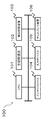
- FIG. 1 is a block diagram of a leak detection apparatus 10 according to the first embodiment.
- the leak detection device 10 in this embodiment includes a subtraction unit 11 and a leak determination unit 12.
- the subtracting unit 11 is based on a first signal acquired from a sensor installed so as to detect leakage sound from the pipe and a second signal acquired from a sensor installed so as to detect ambient noise.
- the noise due to the non-moving sound source is subtracted from the signal, and further the noise due to the moving sound source is subtracted.
- the first signal is a signal that mainly includes a pipe or a sound that propagates through a gas or liquid flowing through the pipe. If the tube is leaking, the first signal includes a leaking sound.
- the sensor for acquiring the first signal is installed in, for example, a pipe or a facility attached to the pipe.
- the second signal is a signal including noise mainly propagating in the surrounding area of the pipe or on the ground surface.
- the second signal includes, for example, noise caused by a non-moving sound source and noise caused by a moving sound source.
- a non-moving sound source is a sound source that emits sound at the same point, such as an object fixed on the ground or a building.
- the moving sound source is a sound source that emits sound while moving, such as a vehicle.
- the sensor that acquires the second signal is installed, for example, on the ground surface or in the ground.
- the subtracting unit 11 obtains, for example, noise due to the non-moving sound source and noise due to the moving sound source using the second signal. Then, the subtracting unit 11 subtracts the noise caused by the non-moving sound source from the first signal using the noise caused by the non-moving sound source and the noise caused by the moving sound source obtained as described above, and further subtracts the noise caused by the moving sound source. .
- the leakage determination unit 12 determines the presence or absence of leakage from the tube based on the result of subtracting noise from the non-moving sound source and the moving sound source from the first signal.
- the leakage determination unit 12 determines the presence or absence of leakage based on the level of a signal indicating the result. For example, the leakage determination unit 12 determines that there is leakage from the pipe when the level of the signal indicating the result is higher than a predetermined level.
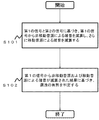
- FIG. 2 is a flowchart showing the operation of the leak detection apparatus 10.
- the subtracting unit 11 subtracts the noise due to the non-moving sound source from the first signal based on the first signal and the second signal, and further subtracts the noise due to the moving sound source (step S101).
- Leakage determination unit 12 determines the presence or absence of leakage based on the result of subtracting noise from the non-moving sound source and the moving sound source from the first signal (step S102).
- the leak detection apparatus 10 having the above configuration subtracts noise caused by a non-moving sound source from the first signal based on the first signal and the second signal, and further subtracts noise caused by the moving sound source.
- the first signal generally includes leaked sound caused by leak and noise caused by a non-moving sound source and a moving sound source.
- the second signal generally includes non-moving sound sources and noise caused by moving sound sources.
- the leak detection device 10 determines whether there is a leak based on the result of subtracting noise from the non-moving sound source and the moving sound source from the first signal. Therefore, the leak detection device 10 can detect leaks from the pipes accurately even in an environment where noise due to the moving sound source is generated by suppressing both noise due to the non-moving sound source and noise due to the moving sound source.
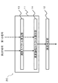
- FIG. 3 is a block diagram of the leak detection device 20 according to the second embodiment.
- the leakage detection device 20 in the present embodiment includes a subtraction unit 11 and a leakage determination unit 12.
- the subtraction unit 11 includes a subtraction spectrum calculation unit 13 and a subtraction amplitude spectrum calculation unit 14.
- the subtraction spectrum calculation unit 13 calculates the subtraction spectrum of the first signal and the spectrum of the second signal based on the first signal and the second signal.
- the subtraction spectrum of the first signal indicates, for example, a spectrum obtained by subtracting noise from a non-moving sound source from the spectrum of the first signal.
- the subtraction amplitude spectrum calculation unit 14 calculates the amplitude spectrum of the first signal based on the subtraction spectrum of the first signal and the spectrum of the second signal.
- the amplitude spectrum of the first signal indicates, for example, an amplitude spectrum obtained by subtracting noise from the non-moving sound source and the moving sound source from the spectrum of the first signal.
- the leakage determination unit 12 determines whether there is leakage from the tube from the amplitude spectrum of the first signal obtained by subtracting noise from the non-moving sound source and the moving sound source. The leak determination unit 12 determines whether there is a leak from the tube based on the magnitude of the amplitude indicated by the amplitude spectrum of the first signal.
- FIG. 4 is a flowchart showing the operation of the leak detection device 20.
- the subtraction spectrum calculation unit 13 calculates the subtraction spectrum of the first signal and the spectrum of the second signal based on the first signal and the second signal (step S201).
- the subtraction amplitude spectrum calculation unit 14 calculates the amplitude spectrum of the first signal based on the subtraction spectrum of the first signal and the spectrum of the second signal (step S202).
- Leakage determination unit 12 determines the presence or absence of leakage of the tube from the amplitude spectrum of the first signal (step S203).
- the leak detection device 20 having the above configuration calculates the subtraction spectrum of the first signal and the spectrum of the second signal based on the first signal and the second signal.
- the subtracted spectrum of the first signal indicates a spectrum obtained by subtracting noise from a non-moving sound source from the spectrum of the first signal, for example.
- the leak detection device 20 calculates the amplitude spectrum of the first signal based on the subtraction spectrum of the first signal and the spectrum of the second signal.
- the amplitude spectrum of the first signal indicates, for example, an amplitude spectrum obtained by subtracting noise from the non-moving sound source and the moving sound source from the spectrum of the first signal.
- the leak detection device 20 determines whether there is a leak from the tube from the amplitude spectrum of the first signal.
- the leak detection apparatus 20 determines the amplitude spectrum of the first signal in which both the noise caused by the non-moving sound source and the noise caused by the moving sound source are suppressed. It is possible to detect leaks from piping well.
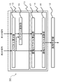
- FIG. 5 is a block diagram of the leak detection device 30 in the third embodiment.
- the leak detection device 30 in the present embodiment includes the subtraction unit 11 and the leak determination unit 12.
- the subtraction unit 11 includes a subtraction spectrum calculation unit 13 and a subtraction amplitude spectrum calculation unit 14.
- the subtraction spectrum calculation unit 13 includes a spectrum calculation unit 15 and a spectrum subtraction unit 16.
- the subtraction amplitude spectrum calculation unit 14 includes an amplitude spectrum calculation unit 17 and an amplitude spectrum subtraction unit 18.
- the spectrum calculation unit 15 is a spectrum of the tube signal from the first signal (hereinafter sometimes referred to as “tube signal”) and the second signal (hereinafter sometimes referred to as “ground signal”).
- a ground signal spectrum that is a tube signal spectrum and a ground signal spectrum is calculated.
- the tube signal is acquired by a sensor installed in, for example, a tube or a facility attached to the tube.
- the ground signal is acquired by a sensor installed on the ground surface or underground.
- the spectrum calculation unit 15 calculates the tube signal spectrum X 1, i (f) , which is the frequency spectrum of the tube signal, from the tube signal x 1 (t) by Fourier transform, wavelet transform, or the like.
- the spectrum calculating unit 15 for example, from the ground signal x 2 (t), similarly calculated is a frequency spectrum of the ground Ground signal spectrum X 2, i (f).
- X 1, i (f) and X 2, i (f) are spectra of the frequency f at the i-th time.
- X 1, i (f) and X 2, i (f) include both an amplitude component and a phase component. Therefore, X 1, i (f) and X 2, i (f) are represented by complex numbers.
- the spectrum subtraction unit 16 subtracts the product of the subtraction spectrum coefficient and the ground signal spectrum from the tube signal spectrum. For example, the spectrum subtraction unit 16 calculates a subtraction spectrum obtained by subtracting the ground spectrum X 2, i (f) from the tube signal spectrum X 1, i (f). As described above, since X 1, i (f) and X 2, i (f) both include both an amplitude component and a phase component, there is a correlation between both the time variation of the amplitude and the time variation of the phase. The effect of subtracting noise increases. That is, the spectrum subtracting unit 16 can subtract noise caused by a non-moving sound source, which is noise with high coherence between X 1, i (f) and X 2, i (f). That is, the subtracted spectrum is a spectrum obtained by subtracting noise due to a non-moving sound source from the tube signal spectrum. The spectrum subtracting unit 16 calculates a subtracted spectrum using, for example, Equation 1 (hereinafter described as Equation 1).
- the subtracted spectrum S a, i (f) is subtracted from the tube signal spectrum X 1, i (f) (hereinafter, may be referred to as “first coefficient”) k. It is calculated by subtracting the product of a (f) and the ground spectrum X 2, i (f). Subtraction spectral coefficients k a (f) is calculated using equation 2.
- Equation 3 E [
- R 12 (f) is a correlation coefficient between X 1, i (f) and X 2, i (f), and is expressed by Equation 3.
- X 2, i * (f) is a complex conjugate of X 2, i (f).
- Formula 2 is derived
- X 1, i (f) can be expressed using Equation 4. The reason is that the ground signal spectrum X 2, i (f) mainly includes a noise component and the leaked sound component C i (f) is hardly included, and the tube signal spectrum X 1, i This is because (f) includes the leaked sound component C i (f) and the noise component k a (f) X 2, i (f) transmitted from the ground.
- Equation 5 the time average of the product of X 1, i (f) and X 2, i (f) is expressed by Equation 5.
- Equation 6 Equation 6
- Equation 2 is derived by applying Equation 3 to Equation 6.
- noise which is represented by the number 4, by using the subtraction method in the spectral subtraction unit 16 to use the number 1 to number 6 for subtraction spectral coefficients k a (f), is suppressed.
- the more noise components are included in the tube signal that is, the greater the correlation between the tube signal spectrum and the ground signal spectrum, the greater the proportion of subtraction of the ground signal.
- the amplitude spectrum calculation unit 17 calculates the amplitude spectrum of the tube signal and the amplitude spectrum of the ground signal obtained by subtracting noise from the non-moving sound source from the subtraction spectrum and the ground signal spectrum.
- the amplitude spectrum of the tube signal indicates the amplitude component of the subtracted spectrum, which is the tube signal spectrum calculated by the spectrum subtracting unit 16 and subtracted with noise due to the non-moving sound source.
- the amplitude spectrum calculation unit 17 calculates the amplitude spectrum of the tube signal from Equation 7.
- the amplitude spectrum Y 1, i (f) of the tube signal is the absolute value of the subtraction spectrum S a, i (f).
- the amplitude spectrum calculation unit 17 calculates the amplitude spectrum of the ground signal, which is the amplitude component of the ground signal spectrum calculated by the spectrum calculation unit 15, from Equation 8.
- the amplitude spectrum Y 2, i (f) of the ground signal is the absolute value of the ground signal spectrum X 2, i (f).
- the amplitude spectrum subtracting unit 18 calculates a subtracted amplitude spectrum Sb, i (f) by subtracting a correlated component of the ground amplitude spectrum Y 2, i (f) from the tube amplitude spectrum Y 1, i (f). To do.
- the subtracted amplitude spectrum can be regarded as corresponding to the amplitude component of the spectrum obtained by subtracting noise from the moving sound source from the subtracted spectrum.
- Equations (9) and (10) show that Y 1, i (f) and Y 2, i (f) are fixed signal components B 1 (f) and B 2 (f), which are fixed signal components, respectively. It is represented by fluctuation components Z 1, i (f) and Z 2, i (f) which are signal components.
- the “fixed signal component” is a signal component with small temporal variation.
- the “variable signal component” is a signal component having temporal variation.
- Amplitude spectrum Y2 of the ground signal, i (f) is expressed by the sum of the variation component of the ground signal Z2, and i (f) fixing component of the ground signals B 2 and (f).
- the amplitude spectrum Y 1, i (f) of the tube signal is represented by the sum of the fluctuation component Z 1, i (f) of the tube signal and the fixed component B 1 (f) of the tube signal.
- the fluctuation component Z 1, i (f) of the tube signal mainly includes a noise component.
- the fluctuation component Z 1, i (f) of the tube signal is a noise component Z 12, i (f) transmitted from the ground as shown in Equation 11 and other noise components Z 11, i (f). It can be expressed as a sum.
- the amplitude spectrum subtraction unit 18 subtracts the noise component Z 12, i (f) transmitted from the ground. This is represented by Equation 12.
- the noise component Z 12, i (f) transmitted from the ground or the like is a subtracted amplitude spectrum coefficient (hereinafter sometimes referred to as “second coefficient”) k b (f) and a ground fluctuation component Z 2.
- i is the product of (f).
- the amplitude spectrum subtraction unit 18 calculates the subtraction amplitude spectrum S b, i (f) using Equation 13.
- the subtracted amplitude spectrum S b, i (f) is the product of the subtracted amplitude spectrum coefficient k b (f) and the ground fluctuation component Z 2, i (f) from the amplitude spectrum Y 1 , i (f) of the tube signal. Is calculated by subtracting.
- the subtracted amplitude spectrum coefficient k b (f) is 1 when the amplitude components of the tube signal and the ground signal are approximately the same, for example, the distance to the noise source is sufficiently larger than the distance between the two sensors. Further, the subtraction amplitude spectrum coefficient k b (f) is calculated using Equation 14 in the same manner as in the case of the subtraction spectrum coefficient k a (f), for example.
- Y ′ 1, i (f) and Y ′ 2, i (f) represent fluctuation components from the average of Y 1, i (f) and Y 2, i (f), respectively. It is represented by each of Equation 16.
- Equation 15 which is the fluctuation component of the tube signal amplitude spectrum Y 1, i (f) Y '1, i (f) is the amplitude spectrum Y 1, i (f) a tube signal tube signal It is expressed as a difference from the time average E [Y 1, i (f)] of the amplitude spectrum Y 1, i (f).
- Equation 16 Y ′ 2, i (f) , which is a fluctuation component of the amplitude spectrum Y 2, i (f) of the ground signal, represents the amplitude spectrum Y 2, i (f) of the ground signal and the amplitude of the ground signal. It is expressed as a difference from the time average E [Y 2, i (f)] of the spectrum Y 2, i (f).
- R b 12 (f) described on the right side of Equation 14 is a correlation coefficient when calculated from Y ′ 1, i (f) and Y ′ 2, i (f).
- B 2 (f) is calculated, for example , as the minimum value of the moving average value of Y 2, i (f), the 25th percentile value, the median value, the average value, or the like. Further, when the fixed component B 1 of the pipe signal (f) is assumed to be a component that is propagated from the fixed component B 1 of the ground signal (f), instead of the number 13, number 19 can be used.
- K d (f) B 2 (f) which is the third term on the right-hand side of Equation 19, cannot be captured by coherence or amplitude coherence (coherence calculated only from the amplitude component) in noise propagating from the ground signal to the tube.
- the noise component that cannot be captured by coherence or amplitude coherence is a noise component that cannot be subtracted in Equations 1 and 13 because both the coherence and the amplitude coherence are small.
- the coefficient k d (f) is an arbitrary real number.
- the coefficient k d (f) may be set to an optimum value from actual measurement, or the subtraction amplitude spectrum coefficient k b (f) may be used as the coefficient k d (f). If these values are not known, the coefficient k d (f) may be set to zero.
- Expression 19 can be transformed to Expression 20.
- the leakage determination unit 12 determines the presence or absence of leakage from the subtraction spectrum 2 calculated by the amplitude spectrum subtraction unit 18. For example, the leakage determination unit 12 determines the presence or absence of leakage based on the presence or absence of a spectrum peak or spectrum variation characteristic of leakage. The leak determination unit 12 may cause the subtracted spectrum 2 to be displayed as a spectrogram on a display device (not shown). In this case, the operator may determine whether or not there is a spectrum peak or spectrum fluctuation characteristic of leakage. In addition, the leak determination unit 12 has a leak if f exists such that the sound pressure level for each frequency f calculated based on the amplitude and power of the subtraction spectrum 2 exceeds a preset threshold value ⁇ (f). May be determined.
- 2 for the time i is used.
- the influence of sudden noise that cannot be subtracted by the amplitude spectrum subtracting unit 18 can be minimized.
- the minimum value of the moving average value, the 25th percentile value, the median value, the average value, or the like may be used.
- the range of time i is set to be sufficiently long with respect to the noise generation time.
- the threshold value ⁇ (f) may be obtained from an empirical value, or a background noise spectrum is calculated from a signal measured at a past non-leakage or a signal measured at a place without other leakage, and the sound of the background noise spectrum is calculated. It may be determined as a pressure level.
- the leak determination unit 12 automatically determines that there is a leak when a spectrum peak that is continuously generated over a certain time or a spectrum peak that is stably generated is detected. Also good.
- the leakage determination unit 12 may perform comparison with the background noise spectrum and determine that there is leakage when there is a change, such as when a peak that does not appear in the background noise spectrum appears.
- FIG. 6 is a flowchart showing the operation of the leak detection device 30.
- the spectrum calculation unit 15 calculates the spectrum of the tube signal and the spectrum of the ground signal from the tube signal and the ground signal (step S301).
- the spectrum subtracting unit 16 subtracts the product of the subtracted spectrum coefficient and the spectrum of the ground signal from the spectrum of the tube signal (step S302).
- the subtraction spectral coefficient (first coefficient) is calculated based on, for example, the correlation coefficient between the spectrum of the tube signal and the spectrum of the ground signal.
- the amplitude spectrum calculation unit 17 calculates the amplitude spectrum of the tube signal and the amplitude spectrum of the ground signal from the spectrum of the tube signal and the spectrum of the ground signal obtained by subtracting the product of the subtracted spectrum coefficient and the spectrum of the ground signal (step S303). .
- the subtraction amplitude spectrum calculation unit 18 subtracts the product of the subtraction amplitude spectrum coefficient (second coefficient) and the amplitude spectrum of the ground signal from the amplitude spectrum of the tube signal (step S304).
- the leak determination unit 12 determines whether or not there is a leak from the tube from the subtracted amplitude spectrum of the tube signal (step S305).
- the leak detection device 30 having the above configuration calculates the subtraction spectrum and the spectrum of the ground signal based on the tube signal and the ground signal.
- the leak detection device 30 calculates a subtraction amplitude spectrum based on the subtraction spectrum and the spectrum of the ground signal.
- the leak detection device 30 determines whether or not there is a leak in the pipe using the subtracted amplitude spectrum.
- the leak detection device 30 performs leak detection using the feature that the correlation of the noise amplitude spectrum by the moving sound source is large between the tube signal and the ground signal.
- the leak detection device 30 performs spectral subtraction in two stages.
- the leak detection device 30 subtracts noise with high coherence in the first stage and subtracts noise with high amplitude coherence in the second stage.
- the leak detection device 30 determines the subtraction amplitude spectrum in which both the noise caused by the non-moving sound source and the noise caused by the moving sound source are suppressed. Leakage can be detected.
- the noise suppression effect is low particularly in a high frequency band of noise caused by a moving sound source.
- the leak detection device 30 in this embodiment has a high noise suppression effect even in a high frequency band.
- the leak detection apparatus 30 in the present embodiment uses a spectral subtraction method instead of noise suppression by the adaptive digital filter used in the method of Patent Document 1. Therefore, the leak detection device 30 also has an effect that the calculation time is shorter than that of the method described in Patent Document 1.
- FIG. 7 is a block diagram of the leak detection device 40 according to the fourth embodiment.
- the leak detection device 40 includes a subtraction unit 11, a subtraction amplitude spectrum calculation unit 14, and a leak determination unit 12.
- the subtraction unit 11 includes an adaptive noise cancellation unit 19 and a spectrum calculation unit 15.
- the adaptive noise cancellation unit 19 calculates a noise suppression signal, which is a tube signal subjected to noise suppression, using an adaptive digital filter calculated using the ground signal.
- the noise suppression signal is a signal in which noise due to a non-moving sound source is suppressed using an adaptive digital filter among noises other than leakage sound included in the tube signal. That is, the noise suppression signal is a tube signal obtained by subtracting noise from a non-moving sound source.
- the adaptive digital filter coefficient is a coefficient estimated using, for example, a least square method algorithm.
- the spectrum calculation unit 15 calculates the spectrum of the noise suppression signal and the spectrum of the ground signal from the noise suppression signal and the ground signal.
- the spectrum calculation unit 15 calculates each spectrum by, for example, Fourier transform.
- the subtraction amplitude spectrum calculation unit 14 calculates the amplitude spectrum of the tube signal from which the noise due to the non-moving sound source and the moving sound source is subtracted based on the spectrum of the noise suppression signal and the spectrum of the ground signal.
- the leakage determination unit 12 determines the presence or absence of leakage based on the result of subtracting noise from the non-moving sound source and the moving sound source from the tube signal. That is, the leakage determination unit 12 determines whether there is leakage based on the subtracted amplitude spectrum of the tube signal.
- FIG. 8 is a flowchart showing the operation of the leak detection device 40.
- the adaptive noise cancellation unit 19 calculates a noise suppression signal based on the adaptive digital filter calculated using the tube signal and the ground signal (step S401).
- the spectrum calculation unit 15 calculates the spectrum of the noise suppression signal and the spectrum of the ground signal from the noise suppression signal and the ground signal (step S402).
- the subtraction amplitude spectrum calculation unit 14 calculates the amplitude spectrum of the tube signal from which the noise due to the non-moving sound source and the moving sound source is subtracted based on the spectrum of the noise suppression signal and the spectrum of the ground signal (step S403).
- the leakage determination unit 12 determines the presence or absence of leakage based on the result obtained by subtracting noise from the non-moving sound source and the moving sound source from the tube signal (step S404).
- the leak detection apparatus 40 having the above configuration suppresses noise caused by a non-moving sound source by adaptive noise cancellation, and then suppresses noise caused by the moving sound source using a spectral subtraction method. Thereby, since both the noise by a non-moving sound source and the noise by a moving sound source as described in the first to third embodiments can be suppressed, leakage detection can be performed with high accuracy. Furthermore, the leak detection device 40 can also suppress noise caused by a non-moving sound source in which the leaky sound and the frequency band overlap.
- FIG. 9 is a block diagram of a leak detection system 50 according to the fifth embodiment.
- the leak detection system 50 in this embodiment includes a leak detection device 10, a first sensor 21, and a second sensor 22.
- the leak detection apparatus 10 in the present embodiment has the same configuration and function as the leak detection apparatus 10 in the first embodiment. In the present embodiment, description of the leak detection device 10 is omitted. Further, instead of the leak detection device 10, the leak detection device in the second to fourth embodiments of the present invention may be used.
- the first sensor 21 is installed in a pipe or a facility attached to the pipe.
- the first sensor 21 detects sound or vibration propagating through a tube or a gas or liquid flowing through the tube.
- the first sensor 21 outputs a tube signal indicating the detected sound or vibration to the leak detection device 10.
- the second sensor 22 is installed in the ground or on the ground surface.
- the second sensor 22 detects sound or vibration that propagates in the ground or on the ground.
- the second sensor 22 outputs a ground signal indicating the detected sound or vibration to the leak detection device 10.
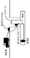
- FIG. 10 is a diagram illustrating an example of installation locations of the first sensor 21 and the second sensor 22.
- the 1st sensor 21 is installed in the position which leaks sound, such as the installation accompanying a piping and piping, for example. That is, the 1st sensor 21 is installed in the position which can detect the leak sound from a pipe.
- the second sensor 22 is installed on the ground or underground. In the example shown in FIG. 10, the second sensor 22 is directly installed on the ground. That is, the second sensor 22 is installed at a position where ambient noise of the tube can be detected.
- FIG. 11 is a flowchart showing the operation of the leak detection system 50.
- the first sensor 21 and the second sensor 22 detect sounds and signals propagating through pipes and underground, respectively, and output the detected sounds to the leak detection device 10 as tube signals or ground signals (step S501). .
- the subtracting unit 11 subtracts the noise due to the non-moving sound source from the tube signal based on the tube signal and the ground signal output from the first sensor 21 and the second sensor 22, and further subtracts the noise due to the moving sound source (step). S502).
- the leakage determination unit 12 determines the presence or absence of leakage based on the result of subtracting noise from the non-moving sound source and the moving sound source from the tube signal (step S503).
- the leak detection system 50 having the above configuration subtracts noise due to the non-moving sound source from the tube signal based on the tube signal and the ground signal, and further subtracts noise due to the moving sound source.
- the leak detection system 50 determines whether or not there is a leak based on the result of subtracting noise from the non-moving sound source and the moving sound source from the tube signal. Therefore, the leak detection system 50 can accurately detect leaks from the piping even in an environment where noise due to the moving sound source is generated by suppressing both noise due to the non-moving sound source and noise due to the moving sound source.
- FIG. 12 is a schematic block diagram showing a configuration example of the computer 100 in each embodiment of the present invention.
- the computer 100 includes a CPU 101, a main storage device 102, an auxiliary storage device 103, an interface 104, an input device 105, and a display device 106.
- the leakage detection apparatus 10 and the like of each embodiment and each example are mounted on a computer 100.
- the operation of the leak detection device 10 and the like is stored in the auxiliary storage device 103 in the form of a program.
- the CPU 101 reads out the program from the auxiliary storage device 103 and develops it in the main storage device 102, and executes the above processing according to the program.
- the auxiliary storage device 103 is an example of a tangible medium that is not temporary.
- Other examples of the non-temporary tangible medium include a magnetic disk, a magneto-optical disk, a CD-ROM, a DVD-ROM, and a semiconductor memory connected via the interface 104.
- the interface 104 is connected to the CPU 101 and connected to a network or an external storage medium. External data may be taken into the CPU 101 via the interface 104.
- the input device 105 is, for example, a keyboard, a mouse, or a touch panel.
- the display 106 displays a screen corresponding to drawing data processed by the CPU 101 or GPU (Graphics Processing Unit) (not shown) such as an LCD (Liquid Crystal Display) or CRT (Cathode Ray Tube) display. Device. Note that the hardware configuration illustrated in FIG. 12 is merely an example, and each unit illustrated in FIG. 1 may be configured with independent logic circuits.
- the program may realize a part of the above processing.
- the program may be a differential program that realizes the above-described processing in combination with another program already stored in the auxiliary storage device 103.
Landscapes
- Physics & Mathematics (AREA)
- General Physics & Mathematics (AREA)
- Examining Or Testing Airtightness (AREA)
Abstract
L'invention concerne la détection précise d'une fuite dans une conduite, même dans un environnement où se produit du bruit dû au déplacement de sources de bruit. Un aspect de la présente invention réalise un dispositif de détection de fuite comprenant : une unité de soustraction destinée à soustraire le bruit provenant de sources de bruit non mobiles d'un premier signal, en se basant sur le premier signal qui est acquis à partir d'un capteur installé à un emplacement auquel il est possible de détecter le bruit de fuite provenant d'un tuyau, et sur un deuxième signal qui est acquis à partir d'un capteur installé à un emplacement auquel il est possible de détecter un bruit ambiant, et à soustraire en plus le bruit provenant de sources de bruit mobiles ; et une unité d'évaluation de fuite destinée à évaluer l'existence d'une fuite, en se basant sur le résultat de la soustraction du bruit provenant de sources de bruit non mobiles et des sources de bruit mobiles du premier signal.
Priority Applications (1)
| Application Number | Priority Date | Filing Date | Title |
|---|---|---|---|
| JP2017507494A JP6773026B2 (ja) | 2015-03-25 | 2016-03-18 | 漏洩検知装置、漏洩検知システム、漏洩検知方法及びコンピュータ読み取り可能記録媒体 |
Applications Claiming Priority (2)
| Application Number | Priority Date | Filing Date | Title |
|---|---|---|---|
| JP2015061853 | 2015-03-25 | ||
| JP2015-061853 | 2015-03-25 |
Publications (1)
| Publication Number | Publication Date |
|---|---|
| WO2016152131A1 true WO2016152131A1 (fr) | 2016-09-29 |
Family
ID=56978127
Family Applications (1)
| Application Number | Title | Priority Date | Filing Date |
|---|---|---|---|
| PCT/JP2016/001590 Ceased WO2016152131A1 (fr) | 2015-03-25 | 2016-03-18 | Dispositif de détection de fuite, système de détection de fuite, procédé de détection de fuite, et support d'enregistrement lisible par ordinateur |
Country Status (2)
| Country | Link |
|---|---|
| JP (1) | JP6773026B2 (fr) |
| WO (1) | WO2016152131A1 (fr) |
Cited By (2)
| Publication number | Priority date | Publication date | Assignee | Title |
|---|---|---|---|---|
| TWI630379B (zh) * | 2017-02-08 | 2018-07-21 | 逸奇科技股份有限公司 | 一種測漏系統 |
| US20210325005A1 (en) * | 2018-09-04 | 2021-10-21 | Nec Corporation | Fluid leakage diagnosing device, fluid leakage diagnosing system, fluid leakage diagnosing method, and recording medium storing fluid leakage diagnosing program |
Families Citing this family (1)
| Publication number | Priority date | Publication date | Assignee | Title |
|---|---|---|---|---|
| JP7794508B1 (ja) * | 2025-03-26 | 2026-01-06 | 広州華科環保工程有限公司 | 水汚染源の排水及び排水管の監視システム及び方法 |
Citations (5)
| Publication number | Priority date | Publication date | Assignee | Title |
|---|---|---|---|---|
| JPH0522171B2 (fr) * | 1985-03-29 | 1993-03-26 | Tokyo Shibaura Electric Co | |
| JPH06323945A (ja) * | 1993-05-11 | 1994-11-25 | Tohoku Electric Power Co Inc | 弁漏洩探知装置 |
| JP4172241B2 (ja) * | 2002-10-02 | 2008-10-29 | Jfeスチール株式会社 | 配管の漏洩位置検知方法および装置 |
| WO2014051036A1 (fr) * | 2012-09-28 | 2014-04-03 | 日本電気株式会社 | Dispositif de détection de fuite, procédé de détection de fuite et programme |
| JP2014219342A (ja) * | 2013-05-10 | 2014-11-20 | 積水化学工業株式会社 | 埋設管路の漏洩検出方法および装置 |
-
2016
- 2016-03-18 JP JP2017507494A patent/JP6773026B2/ja active Active
- 2016-03-18 WO PCT/JP2016/001590 patent/WO2016152131A1/fr not_active Ceased
Patent Citations (5)
| Publication number | Priority date | Publication date | Assignee | Title |
|---|---|---|---|---|
| JPH0522171B2 (fr) * | 1985-03-29 | 1993-03-26 | Tokyo Shibaura Electric Co | |
| JPH06323945A (ja) * | 1993-05-11 | 1994-11-25 | Tohoku Electric Power Co Inc | 弁漏洩探知装置 |
| JP4172241B2 (ja) * | 2002-10-02 | 2008-10-29 | Jfeスチール株式会社 | 配管の漏洩位置検知方法および装置 |
| WO2014051036A1 (fr) * | 2012-09-28 | 2014-04-03 | 日本電気株式会社 | Dispositif de détection de fuite, procédé de détection de fuite et programme |
| JP2014219342A (ja) * | 2013-05-10 | 2014-11-20 | 積水化学工業株式会社 | 埋設管路の漏洩検出方法および装置 |
Cited By (3)
| Publication number | Priority date | Publication date | Assignee | Title |
|---|---|---|---|---|
| TWI630379B (zh) * | 2017-02-08 | 2018-07-21 | 逸奇科技股份有限公司 | 一種測漏系統 |
| US20210325005A1 (en) * | 2018-09-04 | 2021-10-21 | Nec Corporation | Fluid leakage diagnosing device, fluid leakage diagnosing system, fluid leakage diagnosing method, and recording medium storing fluid leakage diagnosing program |
| US11703189B2 (en) * | 2018-09-04 | 2023-07-18 | Nec Corporation | Fluid leakage diagnosing device, fluid leakage diagnosing system, fluid leakage diagnosing method, and recording medium storing fluid leakage diagnosing program |
Also Published As
| Publication number | Publication date |
|---|---|
| JP6773026B2 (ja) | 2020-10-21 |
| JPWO2016152131A1 (ja) | 2018-01-18 |
Similar Documents
| Publication | Publication Date | Title |
|---|---|---|
| CN105659080B (zh) | 用于从来自阀的声能中过滤噪声的系统和方法 | |
| US10458878B2 (en) | Position determination device, leak detection system, position determination method, and computer-readable recording medium | |
| JP6413741B2 (ja) | 振動発生源推定装置、方法およびプログラム | |
| JP6773026B2 (ja) | 漏洩検知装置、漏洩検知システム、漏洩検知方法及びコンピュータ読み取り可能記録媒体 | |
| US11703189B2 (en) | Fluid leakage diagnosing device, fluid leakage diagnosing system, fluid leakage diagnosing method, and recording medium storing fluid leakage diagnosing program | |
| US10948376B2 (en) | Apparatus and method of detecting leak sound in plant equipment using time-frequency transformation | |
| KR101381469B1 (ko) | 매설배관 누설 탐지용 상호상관함수기법의 정확도 향상을 위한 기계 잡음 제거 방법 | |
| JP2019124867A (ja) | アクティブノイズコントロールされる音場のシミュレーション方法及びシミュレーション装置 | |
| JPWO2015068343A1 (ja) | 漏洩位置算出装置、漏洩位置算出方法、コンピュータ読み取り可能な記録媒体、振動算出装置、及び演算装置 | |
| US10979833B2 (en) | Acoustical performance evaluation method | |
| JP6408929B2 (ja) | 分析データ作成方法、漏水位置検知装置および漏水位置特定方法 | |
| US10156493B2 (en) | Position determination device, position determination system, position determination method, and computer-readable recording medium | |
| US11448565B2 (en) | Measurement time determination device, measurement time determination method, and computer-readable recording medium | |
| WO2016185726A1 (fr) | Dispositif d'évaluation d'état, procédé d'évaluation d'état et support d'enregistrement de programme | |
| JP2018205192A (ja) | 漏水位置特定方法、漏洩有無判定方法 | |
| JP2020148462A (ja) | 水道管漏水解析装置 | |
| JP2014219342A (ja) | 埋設管路の漏洩検出方法および装置 | |
| JP2017083292A (ja) | 管路の異常の判定方法 | |
| JPWO2015146109A1 (ja) | 欠陥分析装置、欠陥分析方法および欠陥分析プログラム | |
| WO2023286147A1 (fr) | Système d'observation de quantité de sable mouvant, appareil d'observation de quantité de sable mouvant, procédé d'observation de quantité de sable mouvant et support lisible par ordinateur | |
| JP2019174536A (ja) | アクティブノイズコントロールによる音場シミュレーションの評価方法及び評価装置 | |
| JP2015190824A (ja) | 漏洩検知装置、漏洩検知システム、漏洩検知方法及びプログラム | |
| WO2014050990A1 (fr) | Procédé de détermination de fuite, dispositif de détermination de fuite, terminal de mesure et programme |
Legal Events
| Date | Code | Title | Description |
|---|---|---|---|
| 121 | Ep: the epo has been informed by wipo that ep was designated in this application |
Ref document number: 16768038 Country of ref document: EP Kind code of ref document: A1 |
|
| ENP | Entry into the national phase |
Ref document number: 2017507494 Country of ref document: JP Kind code of ref document: A |
|
| NENP | Non-entry into the national phase |
Ref country code: DE |
|
| 122 | Ep: pct application non-entry in european phase |
Ref document number: 16768038 Country of ref document: EP Kind code of ref document: A1 |