WO2016152202A1 - Dispositif de détection de rotation et système de moteur - Google Patents
Dispositif de détection de rotation et système de moteur Download PDFInfo
- Publication number
- WO2016152202A1 WO2016152202A1 PCT/JP2016/050966 JP2016050966W WO2016152202A1 WO 2016152202 A1 WO2016152202 A1 WO 2016152202A1 JP 2016050966 W JP2016050966 W JP 2016050966W WO 2016152202 A1 WO2016152202 A1 WO 2016152202A1
- Authority
- WO
- WIPO (PCT)
- Prior art keywords
- target
- pickup
- engine
- detection device
- rotation
- Prior art date
- Legal status (The legal status is an assumption and is not a legal conclusion. Google has not performed a legal analysis and makes no representation as to the accuracy of the status listed.)
- Ceased
Links
Images


Classifications
-
- F—MECHANICAL ENGINEERING; LIGHTING; HEATING; WEAPONS; BLASTING
- F02—COMBUSTION ENGINES; HOT-GAS OR COMBUSTION-PRODUCT ENGINE PLANTS
- F02D—CONTROLLING COMBUSTION ENGINES
- F02D45/00—Electrical control not provided for in groups F02D41/00 - F02D43/00
-
- F—MECHANICAL ENGINEERING; LIGHTING; HEATING; WEAPONS; BLASTING
- F02—COMBUSTION ENGINES; HOT-GAS OR COMBUSTION-PRODUCT ENGINE PLANTS
- F02P—IGNITION, OTHER THAN COMPRESSION IGNITION, FOR INTERNAL-COMBUSTION ENGINES; TESTING OF IGNITION TIMING IN COMPRESSION-IGNITION ENGINES
- F02P7/00—Arrangements of distributors, circuit-makers or -breakers, e.g. of distributor and circuit-breaker combinations or pick-up devices
- F02P7/06—Arrangements of distributors, circuit-makers or -breakers, e.g. of distributor and circuit-breaker combinations or pick-up devices of circuit-makers or -breakers, or pick-up devices adapted to sense particular points of the timing cycle
- F02P7/067—Electromagnetic pick-up devices, e.g. providing induced current in a coil
-
- F—MECHANICAL ENGINEERING; LIGHTING; HEATING; WEAPONS; BLASTING
- F02—COMBUSTION ENGINES; HOT-GAS OR COMBUSTION-PRODUCT ENGINE PLANTS
- F02P—IGNITION, OTHER THAN COMPRESSION IGNITION, FOR INTERNAL-COMBUSTION ENGINES; TESTING OF IGNITION TIMING IN COMPRESSION-IGNITION ENGINES
- F02P7/00—Arrangements of distributors, circuit-makers or -breakers, e.g. of distributor and circuit-breaker combinations or pick-up devices
- F02P7/06—Arrangements of distributors, circuit-makers or -breakers, e.g. of distributor and circuit-breaker combinations or pick-up devices of circuit-makers or -breakers, or pick-up devices adapted to sense particular points of the timing cycle
- F02P7/077—Circuits therefor, e.g. pulse generators
-
- G—PHYSICS
- G01—MEASURING; TESTING
- G01D—MEASURING NOT SPECIALLY ADAPTED FOR A SPECIFIC VARIABLE; ARRANGEMENTS FOR MEASURING TWO OR MORE VARIABLES NOT COVERED IN A SINGLE OTHER SUBCLASS; TARIFF METERING APPARATUS; MEASURING OR TESTING NOT OTHERWISE PROVIDED FOR
- G01D5/00—Mechanical means for transferring the output of a sensing member; Means for converting the output of a sensing member to another variable where the form or nature of the sensing member does not constrain the means for converting; Transducers not specially adapted for a specific variable
- G01D5/12—Mechanical means for transferring the output of a sensing member; Means for converting the output of a sensing member to another variable where the form or nature of the sensing member does not constrain the means for converting; Transducers not specially adapted for a specific variable using electric or magnetic means
- G01D5/244—Mechanical means for transferring the output of a sensing member; Means for converting the output of a sensing member to another variable where the form or nature of the sensing member does not constrain the means for converting; Transducers not specially adapted for a specific variable using electric or magnetic means influencing characteristics of pulses or pulse trains; generating pulses or pulse trains
- G01D5/245—Mechanical means for transferring the output of a sensing member; Means for converting the output of a sensing member to another variable where the form or nature of the sensing member does not constrain the means for converting; Transducers not specially adapted for a specific variable using electric or magnetic means influencing characteristics of pulses or pulse trains; generating pulses or pulse trains using a variable number of pulses in a train
Definitions
- the present invention relates to a rotation detection device and an engine system.
- Priority is claimed on Japanese Patent Application No. 2015-059207, filed March 23, 2015, the content of which is incorporated herein by reference.
- the rotation of a flywheel is detected by a flywheel pickup.
- the rotational position of the camshaft is detected by the camshaft pickup.
- Patent Document 1 describes a rotational angle position detection device that generates a crank pulse by rotation of a crankshaft of an engine and generates a cylinder pulse as the cam shaft rotates.
- the rotational angle position detection device described in Patent Document 1 includes a first rotating body, a second rotating body, a first pickup, and a second pickup.
- the first rotating body is interlocked with the rotation of a crankshaft of the engine.
- the first pickup detects a convex portion made of a magnetic material formed on the outer circumference of the first rotating body.
- the second rotating body is interlocked with the rotation of the cam shaft.
- the second pickup detects a convex portion made of a magnetic material formed on the outer circumference of the second rotating body.
- the control device of the engine in Patent Document 1 detects the engine rotational speed based on the detection result of the first pickup, and detects the ignition timing based on the detection result of the second pickup.
- An object of the present invention is to provide a rotation detection device and an engine system that can reduce the number of parts and simplify assembly work, and can suppress an increase in the size of the device.
- a rotation detection device comprises: a rotating body rotatable around the same axis together with an object to be detected; a first target disposed at an outer edge of the rotating body; And a first pick-up disposed adjacent to the radially outer side of the rotation locus of and detecting the passage of the first target.
- the rotation detection device includes a second target disposed at an outer edge of the rotating body and offset in the axial direction of the rotating body with respect to the first target, and a radial direction of a rotation locus of the second target And a second pickup disposed adjacent to the outside and detecting passage of the second target.
- the first pickup and the second pickup have to be arranged in the axial direction while being shifted, it is possible to use the first rotating body without using the plurality of rotating bodies.
- the detection of the first target by the pickup and the detection of the second target by the second pickup can be performed. Therefore, the number of parts can be reduced and the assembling operation can be simplified as compared with the case where the rotating body provided with the first target and the rotating body provided with the second target are separately provided.
- the mounting structure can be simplified as compared to the case where two rotating bodies are arranged side by side. Therefore, the device can be miniaturized by reducing the axial dimension.
- any one of the first target and the second target may be provided with a permanent magnet in the first aspect.
- an engine system includes an engine, a control device that performs drive control of the engine, and the rotation detection device according to claim 1 or 2, wherein the rotation detection device includes: The rotation of the camshaft of the engine is detected, and the detection result is output to the control device.
- the rotation of the cam shaft can be detected by detecting the first target by the first pickup, and the rotation of the cam shaft can be detected by detecting the second target by the second pickup. Therefore, even if the specifications and standards of the output signals of the first pickup and the second pickup are different, the rotation of the cam shaft is individually performed by the first pickup and the second pickup using one rotating body.
- the detection results can be individually output to the control device.
- an engine system includes a first wire connecting the first pickup and the control device, and a second wire connecting the second pickup and the control device.
- the second wiring may be disposed along the first wiring.
- an engine system comprises a flywheel provided at a first end of an output shaft of the engine, a flywheel rotation detection device for detecting rotation of the flywheel, and the flywheel rotation.
- a third wiring connecting the detection device and the control device may be provided.
- the control device is disposed closer to the first end than the central position of the engine in the axial direction of the output shaft, and the rotation detection device is disposed on the cam shaft of the engine in the axial direction of the output shaft. It may be disposed on the side closer to the first end.
- the route of the third wire between the flywheel rotation detection device for detecting the rotation of the flywheel and the control device and the first and second wires between the rotation detection device and the control device can be made common. . Therefore, the burden on the worker who performs the wiring operation can be reduced. Furthermore, the first wiring and the second and third wiring can be shortened by arranging the control device closer to the first end than the central position of the engine. Furthermore, by disposing the rotation detection device closer to the first end, the first, second, and third comparisons with the case where the rotation detection device is disposed closer to the end opposite to the first end than the center position of the engine. The two wires can be sufficiently shortened to suppress the superposition of noise and the like on the first, second and third wires.
- the number of parts can be reduced to simplify the assembling operation, and the increase in size of the device can be suppressed.
- FIG. 3 is a cross-sectional view taken along the line III-III in FIG.
- FIG. 4 is a cross-sectional view taken along the line IV-IV of FIG.
- FIG. 1 is a perspective view showing the configuration of an engine system according to an embodiment of the present invention.
- an engine system 1 of this embodiment includes an engine 2, a generator 3, and a control panel 4.
- the engine 2 of this embodiment can use a V-type engine in which a camshaft is provided on a cylinder.
- the engine 2 is a so-called multi-cylinder engine in which a large number (for example, about 18) of cylinders are arranged in the crankshaft direction.
- the engine 2 in this embodiment is a stationary gas engine that operates by burning a gaseous fuel such as city gas.
- a flywheel 5 is attached to an end of a crankshaft of the engine 2.
- a space 7 is formed between the flywheel 5 and the cylinder head 6 of the engine 2.
- the engine 2 is attached with a camshaft rotation detection device 10 for detecting the rotation of the camshaft 14 (see FIG. 2) and a flywheel rotation detection device 11 for detecting the rotation of the flywheel 5.
- the camshaft rotation detection device 10 and the flywheel rotation detection device 11 are connected to the control board 4 via dedicated wirings 12 a, 12 b and 13 respectively.
- the generator 3 converts rotational energy output from the engine 2 into electrical energy.
- the generator 3 includes a rotor (not shown) linked to a crankshaft (not shown) of the engine 2 via a clutch or the like.
- the generator 3 is disposed in series with the engine 2 such that the axis O1 of the rotor extends in the direction of extending the axis O2 of the crankshaft.
- the power generated by the generator 3 is distributed to various loads via the control panel 4.
- the control panel 4 controls the driving of the engine 2 and the generator 3. More specifically, the control panel 4 supplies the amount of gas supplied to each cylinder of the engine 2 based on the detection results of the camshaft rotation detection device 10 attached to the engine 2 and the flywheel rotation detection device 11. Control the ignition timing etc.
- the adjustment of the gas supply amount to each cylinder is controlled by a controller (not shown) for controlling the opening and closing of a solenoid valve (not shown) provided in a gas supply pipe (not shown) connected to each cylinder.
- the adjustment of the ignition timing can be performed using a controller (not shown) for ignition that collectively controls the ignition timing of the spark plug provided in each cylinder.
- the control panel 4 in this embodiment is disposed on the side closer to the first end to which the flywheel 5 is attached than the central position of the engine 2 in the axial direction of the crankshaft (output shaft).
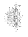
- FIG. 2 is a cross-sectional view of a camshaft rotation detection device in the embodiment of the present invention.
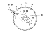
- FIG. 3 is a cross-sectional view taken along the line III-III in FIG.
- FIG. 4 is a cross-sectional view taken along line IV-IV of FIG.
- the camshaft rotation detection device 10 includes a connection member 21, a detection plate 22, a housing 23, and a plurality of pickups 24.
- the connecting member 21 is connected to the end face 15 of the cam shaft 14 by screw action.
- the connecting member 21 extends the cam shaft 14 in the direction of the axis O3.
- the connection member 21 includes a male screw portion 25, a bolt head portion 26, a shaft portion 27 and a plate mounting portion 28.
- the male screw 25 is screwed into a female screw 17 formed on the end face 15 of the cam shaft.
- the bolt head portion 26 is disposed between the male screw portion 25 and the plate mounting portion 28.
- the male screw 25 is screwed into the female screw 17 by rotating the bolt head 26 in a predetermined direction with a tool.
- the shank 27 extends outward from the bolt head 26 along the axis O3.
- a plate mounting portion 28 having a constant outer diameter smaller than the outer diameter on the side of the cam shaft 14 is formed.
- the detection plate 22 is attached to the plate attachment portion 28.
- the detection plate 22 includes a plate body 30, a first target 31, and a second target 32.
- the plate body 30 is formed in a flat plate shape, and has a hole 33 at its center.
- the hole 33 is formed slightly larger in diameter than the plate mounting portion 28 of the shaft portion 27.
- the plate body 30 is fixed to the shaft portion 27 in a state where the plate mounting portion 28 of the shaft portion 27 is inserted into the hole 33.
- the plate mounting portion 28 is inserted into the hole 33 of the plate body 30, and the shaft formed on the back side of the plate mounting portion 28 in the insertion direction
- the plate body 30 is abutted against the step of the part 27.
- the plate body 30 is provided with a first arm portion 37 and a second arm portion 38 extending in the radial direction centering on the hole 33.
- the first arm portion 37 and the second arm portion 38 are formed symmetrically about the hole 33.
- the first arm portion 37 and the second arm portion 38 are formed in a tapered flat plate shape whose width dimension D gradually decreases toward the radially outer side. With such a tapered shape, the increase in inertial force in the first arm portion 37 and the second arm portion 38 is suppressed.
- the thickness in the direction of the axis O3 is increased only at the periphery of the hole 33 in order to ensure sufficient mounting rigidity with respect to the plate mounting portion 28.
- the first target 31 is disposed at the outer edge of the plate main body 30 in the radial direction centering on the axis O3, more specifically, at the outer edge of the first arm portion 37.
- the first target 31 in this embodiment is formed of an unmagnetized metal such as iron.
- the first target 31 has a tapered shape so as to extend the side edge of the first arm 37 radially outward.
- the second target 32 is disposed at the outer edge of the plate body 30 in the radial direction about the axis O3.
- the second target 32 is offset from the first target 31 in the direction of the axis O3.
- a permanent magnet 39 is attached to the second target 32.
- the first target 31 and the second target 32 can be detected by the pickups 24 that are different in material that can be detected.
- the permanent magnet 39 protrudes outward in the radial direction centering on the axis O3 from the second target 32.
- the outer end surface of the second target 32 is disposed more inward in the radial direction centering on the axis O3 than the end surface of the first target 31 as much as the permanent magnet 39 protrudes.
- the pickup 24 includes a first pickup 24 a capable of detecting the passage of the first target 31 and a second pickup 24 b capable of detecting the passage of the second target 32.
- the first pickup 24 a in this embodiment can detect the passage of metal that is not a permanent magnet, and the second pickup 24 b can detect the passage of the permanent magnet 39.
- the first pickup 24 a is disposed adjacent to the outside in the radial direction of the rotation trajectory 31 a of the first target 31. Thus, when the plate body 30 rotates about the axis O3, the first target 31 passes the inside of the first pickup 24a in the circumferential direction in the radial direction about the axis O3.
- the second pickup 24 b is disposed adjacent to the radially outer side of the rotation trajectory 32 a of the second target 32.
- the second target 32 passes the inside of the second pickup 24b in the circumferential direction in the radial direction about the axis O3.
- the distance between the rotation locus 31a of the first target 31 and the radial inner end of the first pickup 24a, and the distance between the rotation locus 32a of the second target 32 and the radial inner end of the second pickup 24b are All are set to be sufficiently small in the range where contact does not occur.
- the first pickup 24a is connected to the control board 4 via a wire (first wire) 12a.
- the second pickup 24b is connected to the control board 4 via a wire (second wire) 12b.
- the wiring 12 a and the wiring 12 b are arranged such that the wiring 12 b is along the wiring 12 a as shown in FIG. 1.
- the wiring 12a and the wiring 12b are respectively connected to the control board 4 from the camshaft rotation detection device 10 through the same route.
- the same route is, for example, passing through the same cable ladder, pit or the like.
- the housing 23 covers the detection plate 22 from the outside.
- the housing 23 includes a housing main body 40, a nozzle mounting portion 41, and a lid 42.
- the housing main body 40 is fixed to the end face 18 of the cylinder head 6 by bolts 43.
- the housing main body 40 includes a bearing 44 that rotatably supports the end 14 a of the cam shaft 14.
- a bearing member 45 for rotatably supporting the shaft portion 27 is mounted on the outer side surface 40 a of the housing main body portion 40.
- the bearing member 45 is fixed to the housing main body 40 by bolts 46 at a plurality of locations in the circumferential direction.
- a restricting member 47 for restricting the displacement of the shaft portion 27 in the direction away from the cam shaft 14 is fixed by bolts 48 at a plurality of locations in the circumferential direction.
- the nozzle attachment portion 41 includes a main body 49, a nozzle 50 and a flange portion 51.
- the main body portion 49 is formed in a cylindrical shape in which the outer peripheral surface of the housing main body portion 40 described above is extended outward along the axis O3.
- the main body 49 covers the plate main body 30 described above from the outer side in the radial direction.
- the flange portion 51 is formed on the opposite side to the housing main body 40 with the main body 49 interposed in the direction of the axis O3.
- the flange portion 51 is formed to extend outward in the radial direction centering on the axis O3.
- the lid portion 42 is formed in a disk shape, and closes the opening of the main body portion 49. The outer edge of the lid 42 is fixed to the flange 51 by bolts 52.
- the nozzle 50 supports the first pickup 24a and the second pickup 24b described above.
- a plurality of nozzles 50 are provided in the main body 49.
- the plurality of nozzles 50 are fixed to the main body 49 by welding or the like.
- the nozzles 50 each have a through hole 53 communicating the inside of the main body 49 with the outside of the main body 49.
- An internal thread is formed on the inner circumferential surface of the nozzle 50.
- the second pickup 24b whose material that can be detected as a target is a permanent magnet, and the first pickup 24a whose material whose detection is possible is a metal other than a permanent magnet are used while using one detection plate 22 each. Can.
- the rotation of the cam shaft 14 can be detected by detecting the first target 31 by the first pickup 24 a
- the rotation of the cam shaft 14 is detected by detecting the second target 32 by the second pickup 24 b. can do. Therefore, even if the specifications and standards of the output signals of the first pickup 24a and the second pickup 24b are different, the rotation of the cam shaft 14 is respectively performed by the first pickup 24a and the second using the single detection plate 22. It is possible to individually detect the detection result by the pickup 24 b and individually output the detection result to the control board 4.
- the wiring 12a and the wiring 12b can be made the same route. As a result, the wiring 12a and the wiring 12b can be easily laid.
- the camshaft rotation detection device 10 having only one detection plate 22, the camshaft rotation detection device 10 can be disposed in the narrow space between the flywheel 5 and the engine 2. Therefore, the routes of the wires 12a and 12b between the flywheel rotation detection device 11 for detecting the rotation of the flywheel 5 and the control board 4 and the wires 13 between the camshaft rotation detection device 10 and the control board 4 are It can be made common. As a result, the burden on the worker who carries out the wiring work can be reduced. Furthermore, by arranging the control board 4 closer to the flywheel 5 than the central position of the engine 2, the wires 12a and 12b and the wire 13 can be shortened.
- the wiring 13 is sufficient compared to the case where the camshaft rotation detection device 10 is arranged on the end side opposite to the flywheel 5 Can be suppressed to suppress noise and the like from being superimposed on the wiring 13.
- the present invention is not limited to the above-described embodiment, and includes the above-described embodiment with various modifications added thereto, without departing from the spirit of the present invention. That is, the specific shape, configuration, and the like described in the embodiment are merely examples, and can be appropriately modified.
- the plate main body 30 of the embodiment described above may be disk-shaped.
- the first target 31 and the second target 32 were arranged at the same position in the circumferential direction has been described, it suffices if the second target 32 is offset with respect to these first targets 31 in the direction of the axis O3.
- the second target 32 may be provided at different positions in the circumferential direction with respect to the first target 31.
- first pickup 24a and the second pickup 24b are provided one by one.
- a plurality of first pickups 24a and second pickups 24b may be provided.
- the first pickups 24 a may be arranged in the circumferential direction on the radially outer side of the rotation trajectory 31 a of the first target 31.
- the second pickups 24 b may be arranged in the circumferential direction outside the radial direction of the rotation trajectory 32 a of the second target 32.
- the case where two sets of the first pickup 24a and the first target 31, and the second pickup 24b and the second target 32 are provided side by side in the direction of the axis O3 has been described.
- three or more sets may be provided for each detectable material.
- three or more targets may be arranged offset with respect to the detection plate 22 in the direction of the axis O3.
- the plurality of targets are arranged to be offset in the direction of the axis O3.
- the pickups may be arranged to face the respective targets.
- the number of parts can be reduced to simplify the assembling operation, and the increase in size of the device can be suppressed.
Landscapes
- Engineering & Computer Science (AREA)
- Chemical & Material Sciences (AREA)
- Combustion & Propulsion (AREA)
- Mechanical Engineering (AREA)
- General Engineering & Computer Science (AREA)
- Physics & Mathematics (AREA)
- General Physics & Mathematics (AREA)
- Electromagnetism (AREA)
- Ignition Installations For Internal Combustion Engines (AREA)
- Transmission And Conversion Of Sensor Element Output (AREA)
- Combined Controls Of Internal Combustion Engines (AREA)
- Measurement Of Length, Angles, Or The Like Using Electric Or Magnetic Means (AREA)
Abstract
L'invention concerne un dispositif de détection de rotation (10) qui comprend un corps rotatif (22) susceptible de tourner conjointement avec un objet à détecter autour de la même ligne d'axe (O3), une première cible (31) qui est disposée au niveau du bord extérieur du corps rotatif (22), un premier capteur (24a) qui est disposé adjacent au côté externe de la première cible (31) dans la direction radiale du lieu de rotation de celle-ci et qui détecte le passage de la première cible (31), une seconde cible (32) qui est disposée au niveau du bord externe du corps rotatif (22) et qui est agencée de manière décalée dans la direction de ligne d'axe du corps rotatif (22) par rapport à la première cible (31), et un second capteur (24b) qui est disposé adjacent au côté externe de la seconde cible (32) dans la direction radiale du lieu de rotation de celle-ci et qui détecte le passage de la seconde cible (32).
Applications Claiming Priority (2)
| Application Number | Priority Date | Filing Date | Title |
|---|---|---|---|
| JP2015-059207 | 2015-03-23 | ||
| JP2015059207A JP2016176904A (ja) | 2015-03-23 | 2015-03-23 | 回転検出装置、および、エンジンシステム |
Publications (1)
| Publication Number | Publication Date |
|---|---|
| WO2016152202A1 true WO2016152202A1 (fr) | 2016-09-29 |
Family
ID=56979087
Family Applications (1)
| Application Number | Title | Priority Date | Filing Date |
|---|---|---|---|
| PCT/JP2016/050966 Ceased WO2016152202A1 (fr) | 2015-03-23 | 2016-01-14 | Dispositif de détection de rotation et système de moteur |
Country Status (2)
| Country | Link |
|---|---|
| JP (1) | JP2016176904A (fr) |
| WO (1) | WO2016152202A1 (fr) |
Cited By (1)
| Publication number | Priority date | Publication date | Assignee | Title |
|---|---|---|---|---|
| CN119086082A (zh) * | 2024-10-12 | 2024-12-06 | 中国航发湖南动力机械研究所 | 一种发动机侧滚试验装置及发动机全姿态试验装置 |
Citations (4)
| Publication number | Priority date | Publication date | Assignee | Title |
|---|---|---|---|---|
| JPS5985443A (ja) * | 1982-11-08 | 1984-05-17 | Toyota Motor Corp | 二分割フライホイ−ルのトルク変動低減装置 |
| JPS63154828A (ja) * | 1986-12-19 | 1988-06-28 | Fuji Heavy Ind Ltd | 内燃機関のクランク角度検出装置 |
| JPS6430412U (fr) * | 1987-08-14 | 1989-02-23 | ||
| JPH0361503U (fr) * | 1989-10-19 | 1991-06-17 |
-
2015
- 2015-03-23 JP JP2015059207A patent/JP2016176904A/ja active Pending
-
2016
- 2016-01-14 WO PCT/JP2016/050966 patent/WO2016152202A1/fr not_active Ceased
Patent Citations (4)
| Publication number | Priority date | Publication date | Assignee | Title |
|---|---|---|---|---|
| JPS5985443A (ja) * | 1982-11-08 | 1984-05-17 | Toyota Motor Corp | 二分割フライホイ−ルのトルク変動低減装置 |
| JPS63154828A (ja) * | 1986-12-19 | 1988-06-28 | Fuji Heavy Ind Ltd | 内燃機関のクランク角度検出装置 |
| JPS6430412U (fr) * | 1987-08-14 | 1989-02-23 | ||
| JPH0361503U (fr) * | 1989-10-19 | 1991-06-17 |
Cited By (1)
| Publication number | Priority date | Publication date | Assignee | Title |
|---|---|---|---|---|
| CN119086082A (zh) * | 2024-10-12 | 2024-12-06 | 中国航发湖南动力机械研究所 | 一种发动机侧滚试验装置及发动机全姿态试验装置 |
Also Published As
| Publication number | Publication date |
|---|---|
| JP2016176904A (ja) | 2016-10-06 |
Similar Documents
| Publication | Publication Date | Title |
|---|---|---|
| US9708997B2 (en) | Control device and control method for internal combustion engine | |
| US11035698B2 (en) | Crank angle detection device | |
| US9074497B2 (en) | Camshaft phaser having a spring attached to the pin of a screw | |
| JP2019504592A (ja) | 特に膨張ストローク及び/又は圧縮比を調節する内燃機関の調節軸へ連結するためのアクチュエータ | |
| JP2014152648A (ja) | 内燃機関のバルブタイミング制御装置 | |
| US4653458A (en) | Arrangement for connecting a position sensing transducer to a machine | |
| US20170254232A1 (en) | Camshaft adjuster having two ball joints | |
| WO2006095532A1 (fr) | Controleur de temporisation d’ouverture/de fermeture de soupape | |
| US11628717B2 (en) | Hybrid drive train | |
| JP2016176904A (ja) | 回転検出装置、および、エンジンシステム | |
| EP1482149A1 (fr) | Agencement d'un capteur pour un moteur à combustion interne | |
| KR20140069348A (ko) | 밸브 개폐 시기 제어 장치 및 그 전방 부재의 고정 방법 | |
| CN100530908C (zh) | 分解器的定子固定结构 | |
| US10578190B2 (en) | Drivetrain module for a motor vehicle | |
| US10190450B2 (en) | Camshaft deactivation system for an internal combustion engine | |
| US20130152890A1 (en) | Camshaft adjuster arrangement and camshaft adjuster | |
| US20020033605A1 (en) | Power transmission structure of a motor assist apparatus for a vehicle | |
| JP7070021B2 (ja) | 固定用プレート | |
| JP6817455B2 (ja) | 内燃機関のバルブタイミング制御装置 | |
| JP4563983B2 (ja) | エンジンの回転角検出装置 | |
| KR20170073799A (ko) | 엔진용 터닝기어 | |
| US20190309769A1 (en) | Hydraulic drive device | |
| US20110303172A1 (en) | Valve drive of an internal combustion engine having an adustment device | |
| JP2007127057A (ja) | バルブタイミング調整装置の取付構造 | |
| JP2024135154A (ja) | ダイナミックダンパ構造 |
Legal Events
| Date | Code | Title | Description |
|---|---|---|---|
| 121 | Ep: the epo has been informed by wipo that ep was designated in this application |
Ref document number: 16768105 Country of ref document: EP Kind code of ref document: A1 |
|
| NENP | Non-entry into the national phase |
Ref country code: DE |
|
| 122 | Ep: pct application non-entry in european phase |
Ref document number: 16768105 Country of ref document: EP Kind code of ref document: A1 |