WO2016152306A1 - Instrument de traitement médical - Google Patents
Instrument de traitement médical Download PDFInfo
- Publication number
- WO2016152306A1 WO2016152306A1 PCT/JP2016/054120 JP2016054120W WO2016152306A1 WO 2016152306 A1 WO2016152306 A1 WO 2016152306A1 JP 2016054120 W JP2016054120 W JP 2016054120W WO 2016152306 A1 WO2016152306 A1 WO 2016152306A1
- Authority
- WO
- WIPO (PCT)
- Prior art keywords
- housing
- operation surface
- exposed
- medical treatment
- width direction
- Prior art date
- Legal status (The legal status is an assumption and is not a legal conclusion. Google has not performed a legal analysis and makes no representation as to the accuracy of the status listed.)
- Ceased
Links
Images








Classifications
-
- A—HUMAN NECESSITIES
- A61—MEDICAL OR VETERINARY SCIENCE; HYGIENE
- A61B—DIAGNOSIS; SURGERY; IDENTIFICATION
- A61B17/00—Surgical instruments, devices or methods
-
- A—HUMAN NECESSITIES
- A61—MEDICAL OR VETERINARY SCIENCE; HYGIENE
- A61B—DIAGNOSIS; SURGERY; IDENTIFICATION
- A61B18/00—Surgical instruments, devices or methods for transferring non-mechanical forms of energy to or from the body
-
- A—HUMAN NECESSITIES
- A61—MEDICAL OR VETERINARY SCIENCE; HYGIENE
- A61B—DIAGNOSIS; SURGERY; IDENTIFICATION
- A61B18/00—Surgical instruments, devices or methods for transferring non-mechanical forms of energy to or from the body
- A61B18/04—Surgical instruments, devices or methods for transferring non-mechanical forms of energy to or from the body by heating
- A61B18/12—Surgical instruments, devices or methods for transferring non-mechanical forms of energy to or from the body by heating by passing a current through the tissue to be heated, e.g. high-frequency current
Definitions
- the present invention relates to a medical treatment instrument including an operation member for performing an operation input by pressing an operation surface.
- Patent Document 3 discloses a pencil-type medical treatment instrument in which a grip and a handle are not provided and a housing main body extends along a longitudinal axis.
- an operation button for performing an operation input by pressing the operation surface is provided, and the operation surface is exposed to the outside on the outer surface (exposed surface) of the housing body.
- the present invention has been made paying attention to the above-mentioned problems, and the object of the present invention is medical treatment in which palms and fingers are effectively prevented from erroneously contacting the operation surface of the operation member when holding the housing. It is to provide a treatment tool.
- a pencil-type medical treatment instrument includes a housing body having a proximal end and a distal end and extending along a longitudinal axis from the proximal end to the distal end, and the housing body includes an external body.
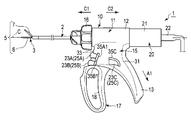
- FIG. 1 is a schematic view showing a medical treatment tool according to the first embodiment.
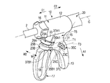
- FIG. 2 is a perspective view schematically showing the holding unit according to the first embodiment.
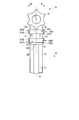
- FIG. 3 is a schematic view of the holding unit according to the first embodiment viewed from the distal end side.
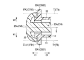
- FIG. 4 is a cross-sectional view schematically showing a configuration of an operation surface of an operation button and its vicinity according to the first embodiment.
- FIG. 5 is a cross-sectional view schematically showing a configuration of an operation surface of an operation button different from that of FIG. 4 according to the first embodiment and the vicinity thereof.
- FIG. 6 is a schematic diagram illustrating a state in which the holding unit according to the first embodiment is held.
- FIG. 1 is a schematic view showing a medical treatment tool according to the first embodiment.
- FIG. 2 is a perspective view schematically showing the holding unit according to the first embodiment.
- FIG. 3 is a schematic view of the holding unit according to the first embodiment viewed from the distal end side.
- FIG. 19 is a schematic diagram illustrating a holding unit according to a first modification of the second embodiment.
- FIG. 20 is a schematic diagram illustrating a holding unit according to a first reference example.
- FIG. 21 is a schematic diagram illustrating a holding unit according to a second reference example.
- FIG. 1 is a view showing a medical treatment instrument 1.
- the medical treatment instrument 1 has a longitudinal axis (central axis) C.
- one side in the direction along the longitudinal axis C is the distal end side (the arrow C1 side in FIG. 1), and the opposite side to the distal end side is the proximal end side (the arrow C2 side in FIG. 1).
- the medical treatment instrument 1 includes a cylindrical sheath 2 extending along the longitudinal axis C and a rod (probe) 3 inserted through the sheath 2.
- the rod 3 includes a rod treatment section (probe treatment section) 6 that protrudes from the distal end of the sheath 2 toward the distal end side.
- a jaw 7 is rotatably attached to the distal end portion of the sheath 2. When the jaw 7 rotates with respect to the sheath 2, the jaw 7 and the rod treatment section 6 are opened and closed.
- the end effector 5 is formed by the rod treatment portion 6 and the jaw 7.
- the medical treatment instrument 1 includes a holding unit 10 and a vibrator unit 20.
- FIG. 2 is a diagram illustrating a configuration of the holding unit 10.
- the holding unit 10 includes a housing 11, and the housing 11 includes a housing body 12 having a proximal end and a distal end.
- the housing body 12 extends along the longitudinal axis C from the proximal end to the distal end.
- the housing 11 also includes a grip (fixed handle) 13 that extends from the housing body 12 in a direction that intersects the longitudinal axis C (the direction of the arrow A1 in FIGS. 1 and 2).
- An exposed surface (outer surface) 15 of the housing 11 is exposed to the outside of the housing 11 at the housing body 12 and the grip 13.
- a rotation operation knob (rotation operation input unit) 16 is connected to the distal end side of the housing body 12 so as to be rotatable about the longitudinal axis C.
- the sheath 2 and the rod 3 are inserted into the inside of the rotary operation knob 16 and the inside of the housing body 12 from the distal end side, and are connected to the holding unit 10.
- the sheath 2, the rod 3 and the jaw 7 By rotating the rotary operation knob 16 about the longitudinal axis C with respect to the housing 11 (housing main body 12), the sheath 2, the rod 3 and the jaw 7 also rotate about the longitudinal axis C.
- the vibrator unit 20 is detachable from the holding unit 10, but the vibrator unit 20 is provided integrally with the holding unit 10, for example, an ultrasonic vibrator is provided inside the housing body 12. May be provided. In this case, one end of the cable 22 is connected to the housing body 12.
- the holding unit 10 includes a handle (movable handle) 17 that can be opened and closed with respect to the grip 13.
- the handle is provided with a force applying unit 18 to which an operating force is applied when the handle 17 is closed with respect to the grip 13.
- the force application unit 18 (handle 17) is located on the same side as the grip 13 with the longitudinal axis C as the center.
- a movable portion (not shown) of the sheath 2 moves along the longitudinal axis C, and the jaw 7 is opened or closed with respect to the rod treatment portion 6.
- the handle 17 is positioned on the distal end side of the grip 13, and the pistol-type holding unit 10 is formed.
- the handle 17 can be opened and closed substantially parallel to the longitudinal axis C.
- buttons 23A to 23C are attached to the housing 11.
- Each of the operation buttons 23A to 23C includes an operation surface (a corresponding one of 25A to 25C) exposed to the outside of the housing 11 on the exposed surface 15 of the housing 11.
- an operation surface (a corresponding one of 25A to 25C) is pressed by an operation input.
- operation switches (not shown) are provided corresponding to the operation buttons 23A to 23C, respectively.
- an imaginary plane S that is a central plane in the width direction in the housing 11 is defined.
- the virtual surface S includes the longitudinal axis C and extends along the extending direction of the grip 13.
- the exposed surface 15 of the housing 11 includes a first housing surface 31 facing the first housing width direction W1, a second housing surface 32 facing the second housing width direction W2, and a distal end side.
- a third housing surface 33 facing (in each of FIGS. 1 and 2, the arrow C1 side).
- the operation surface (one corresponding to 25 ⁇ / b> A and 25 ⁇ / b> B) is pressed from the distal end side by an operation input, or with respect to a cross section perpendicular to the width direction of the housing 11.
- the operation surface (one corresponding to 25A and 25B) is pressed from the intersecting direction. Therefore, each of the operation surfaces 25A and 25B can be pressed from the width direction of the housing 11 in operation input.
- the operation surface 25 ⁇ / b> C of the operation button 23 ⁇ / b> C extends on the first housing surface 31 in the grip 13. That is, the operation surface 25 ⁇ / b> C is located on the exposed surface 15 of the housing 11 at a portion facing one side in the width direction of the housing 11. With the operation button 23 ⁇ / b> C, the operation surface 25 ⁇ / b> C is pressed in a direction intersecting a cross section perpendicular to the width direction of the housing 11 by an operation input. Therefore, the operation surface 25C can be pressed from the width direction of the housing 11 in the operation input.
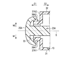
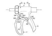
- the portion distal to the virtual surface S of the protrusion 35A1 in the first housing width direction W1 is first from the virtual surface S by the step 37A1 compared to the portion proximal to the protrusion 35A1 of the operation surface 25A. It is located at a far (high) position in the housing width direction W1.
- the part distal to the virtual surface S of the protrusion 35A2 in the second housing width direction W2 is second from the virtual surface S by the step 37A2 compared to the part proximal to the protrusion 35A2 of the operation surface 25A. It is located at a far (high) position in the housing width direction W2.
- each of the protrusions 35A1 and 35A2 has a step in the width direction of the housing 11 in a state where a portion closer to the operation surface 25A is lower (closer to the virtual surface S) than a portion far from the operation surface 25A. (One corresponding to 37A1 and 37A2) is formed. For this reason, at each of the steps 37A1 and 37A2 in the width direction of the housing 11, the position closest to the step (one corresponding to 37A1 and 37A2) at the outer edge of the operation surface 25A is the corresponding step (37A1 and 37A2). ) On the side farther from the operation surface 25A (lower in proximity to the virtual surface S).
- each of the steps 37A1 and 37A2 lowers at least a part of the outer edge of the operation surface 25A as compared to a portion far from the operation surface 25A of the step (corresponding one of 37A1 and 37A2) (virtual surface S). Close to).
- each of the steps 37B1 and 37B2 lowers at least a part of the outer edge of the operation surface 25B as compared to a portion farther from the operation surface 25B of the step (one corresponding to 37B1 and 37B2) (virtual surface S). Close to).
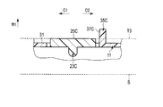
- FIG. 5 is a diagram showing the configuration of the operation surface 25C and the vicinity thereof.
- FIG. 5 is a cross-section substantially parallel to the longitudinal axis C and substantially parallel to the width direction of the housing 11.
- a protrusion 35 ⁇ / b> C is provided as a step forming portion on the first housing surface 31.
- a step 37C is formed in a state of facing the tip side (side close to the operation button 25C).
- the protrusion 35C (step 37C) is located in the vicinity of the operation surface 25C on the first housing surface 31.
- the portion distal to the virtual surface of the projection 35C in the first housing width direction W1 is first step from the virtual surface S by the step 37C compared to the portion proximal to the projection 35C of the operation surface 25C. It is located at a far (high) position in the housing width direction W1.
- the protrusion 35 ⁇ / b> C forms a step 37 ⁇ / b> C in the width direction of the housing 11 in a state where a portion near the operation surface 25 ⁇ / b> C is lower (close to the virtual surface S) than a portion far from the operation surface 25 ⁇ / b> C. .
- the operation surface 25A and the step 37A1 are arranged on a reference straight line T1 that is substantially parallel to the longitudinal axis C of the housing body 12 that passes through the first housing surface 31.
- An operation surface 25A and a step 37A2 are arranged on a reference straight line T2 that is substantially parallel to the longitudinal axis C of the housing body 12 that passes through the second housing surface 32.
- An operation surface 25B, a step 37B1, an operation surface 25C, and a step 37C are arranged on a reference straight line T3 that is substantially parallel to the longitudinal axis C of the housing body 12 that passes through the first housing surface 31.
- the reference straight line T3 passes through a position farther from the longitudinal axis C than the reference straight line T1.
- An operation surface 25B and a step 37B2 are disposed on a reference straight line T4 that is substantially parallel to the longitudinal axis C of the housing body 12 that passes through the second housing surface 32.
- the reference straight line T4 passes through a position farther from the longitudinal axis C than the reference straight line T2.
- the reference straight lines T1 to T4 pass through positions closer to the longitudinal axis C than the force application unit 18 of the handle 17.
- a reference straight line T5 that passes through the first housing surface 31 and connects the base end of the housing body 12 and the force applying portion 18 of the handle 17 is defined.
- the operation surface 25C and the step 37C are arranged on the reference straight line T5.
- FIG. 6 is a view showing a state in which the holding unit 10 is held.
- the thumb F1 located on the first housing surface 31 and the first housing surface 31 to the second housing surface 32 are arranged.
- the grip 13 is sandwiched between the palm P and The index finger F2, the middle finger F3, the ring finger F4, and the little finger F5 are extended through the second housing surface 32.
- the middle finger F3, the ring finger F4, and the little finger F5 are hooked on the force application unit 18 of the handle 17, and when the handle 17 is closed with respect to the grip 13, the operation force is applied to the handle 17 by the middle finger F3, the ring finger F4, and the little finger F5. Applied.
- the operation surface (one corresponding to 25A and 25B) is pressed by the index finger F2.
- the operation surface 25C is pressed by the thumb F1.
- corresponding operation surface corresponding one of 25A to 25C
- the palm P and the fingers F1 to F5 come into contact with the corresponding operation surface (one corresponding to 25A to 25C) by each of the steps 37A1, 37A2, 37B1, 37B2, and 37C.
- the operation surfaces 25A to 25C from being pressed by mistake.
- the treatment of the treatment target is not performed (for example, the end effector 5 toward the treatment target in the body cavity) In this state, energy is prevented from being erroneously supplied to the end effector 5.
- the surgeon intentionally presses any one of the operation surfaces 25A to 25C with the thumb F1 or the index finger F2, and the energy used for the treatment on the end effector 5 ( Ultrasonic vibration and high frequency energy).
- the first housing surface 31 faces the first housing width direction (one side in the housing width direction) and the second housing width direction (the other side in the housing width direction).
- a palm P and fingers F1 to F5 are extended through at least one of the second housing surfaces 32 facing the front.
- the operation surfaces 25A to 25C extend through at least one of the first housing surface 31 and the second housing surface 32.
- the steps 37A1, 37A2, 37B1, 37B2, and 37C in the width direction of the housing 11 are formed, so that the palm P and the fingers F1 to F5 correspond to the steps 37A1, 37A2, 37B1, 37B2, and 37C, respectively. Erroneous contact with the operation surface (corresponding one of 25A to 25C) is further effectively prevented.
- each of the steps 37A1, 37A2, 37B1, 37B2, and 37C has at least the steps (37A1, 37A2, 37B1, 37B2, etc.) on the outer edge of the corresponding operation surface (one corresponding to 25A to 25C).
- the position closest to the corresponding step (one or two of 37A1, 37A2, 37B1, 37B2, 37C) on the outer edge of each of the operation surfaces 25A to 25C is the corresponding step (37A1, 37A2, 37B1, 37B2, 37C corresponding one or two) is lower (close to the virtual surface S) than the part far from the operation surface (corresponding one of 25A to 25C). It is further effectively prevented that F1 to F5 come into contact with the operation surfaces 25A to 25C by mistake.
- An operation surface 25B, a step 37B1, an operation surface 25C, and a step 37C are arranged on a reference straight line T3 that is substantially parallel to the longitudinal axis C of the housing body 12 that passes through.
- An operation surface 25C and a step 37C are disposed on a reference straight line T5 that connects the base end of the housing body 12 and the force application unit 18 of the handle 17. For this reason, contact with the corresponding operation surface (one of 25A and 25B) corresponding to the thumb F1 extending substantially parallel to the longitudinal axis C is more effectively prevented by each of the steps 37A1 and 37B1.
- the step 37C further effectively prevents the palm P extending substantially parallel to the longitudinal axis C or substantially parallel to the reference straight line T5 from contacting the operation surface 25C.
- each of the steps 37A1, 37A2, 37B1, 37B2, and 37C is adjacent to the outer edge of the corresponding operation surface (a corresponding one of 25A to 25C) from the base end side.
- the step 37A1 formed on the protrusion 35A1 and the step 37A2 formed on the protrusion 35A2 are located away from the outer edge of the operation surface 25A toward the base end side.
- the distance from the outer edge of the operation surface 25A to each of the steps 37A1 and 37A2 is small, and the steps 37A1 and 37A2 are located in the vicinity of the operation surface 25A.
- the steps P37A1 and 37A2 prevent the palm P and the fingers F1 to F5 from erroneously contacting the operation surface 25A.
- the separation distances D1 and D2 vary according to the size of the hand and the type of the medical treatment instrument 1, but are at most about 2 cm corresponding to the length from the fingertip to the first joint.
- steps 37B1 and 37B2 may be positioned slightly apart from the outer edge of the operation surface 25B toward the base end as long as the steps 37B1 and 37B2 are located in the vicinity of the operation surface 25B. If it is located in the vicinity, the outer edge of the operation surface 25C may be slightly spaced from the base end side.
- each of the steps 37A1, 37A2, 37B1, 37B2, and 37C is formed by a corresponding protrusion (one corresponding to 35A1, 35A2, 35B1, 35B2, and 35C). It is not limited to.
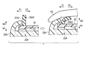
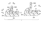
- a step 37A1 is formed by a groove (step forming portion) 38A1 that dents a part of the outer edge of the operation surface 25A with respect to the first housing surface 31.
- a step 37A2 is formed by a groove (step forming portion) 38A2 that makes a part of the outer edge of 25A recessed with respect to the second housing surface 32.
- the projection 35A2 When the operation surface 25A is pressed with the index finger F2 by an operation input, the projection 35A2 is also pressed with the index finger F2, for example, the projection 35A2 is bent toward the side farther from the operation surface 25A (base end side). Since the projection 35A2 is bent toward the proximal end, the operator can easily press the operation surface 25A and can easily perform operation input with the operation button 23A.
- the protrusion 35A2 with which the index finger F2 comes into contact when the operation surface 25A is pressed is formed of a soft elastic material. For this reason, the operator's index finger (finger) F2 does not receive a large reaction force from the protrusion, and the operator can easily perform an operation input with the operation button 23A.
- each structure of the 3rd modification and the 4th modification is applicable also to protrusion 35A1, 35B1, 35B2, 35C other than protrusion 35A2.
- the protrusion 35A2 which is a step forming portion may be removable from the grip 13.
- the protrusion 35A2 is removed from the grip 13 by an assistant or the like when the operation surface 25A is pressed with the index finger F2 by an operation input. This makes it easier for the surgeon to press the operation surface 25A and to perform an operation input with the operation button 23A.
- the projection 35A2 can be removed, a plurality of types of projections 35A2 having different heights relative to each other can be attached to the grip 13.
- protrusions 35A1, 35B1, 35B2, and 35C other than the protrusion 35A2 may be removable from the grip 13 as described in the fifth modification.
- a step 37C is formed by the groove (step forming portion) 38C, and the portion farther from the step 37C on the outer edge of the operation surface 25C (the tip side) is the first housing. It continues to the surface 31 without a step. As a result, a continuous surface is formed between the portion of the operation surface 25 ⁇ / b> C far from the step 37 ⁇ / b> C and the first housing surface 31.
- the portion of the outer edge of the operation surface 25C closer to the step 37C is formed lower than the portion of the step 37C farther from the operation surface 25C. For this reason, the step 37C prevents the palm P and the fingers F1 to F5 from erroneously contacting the operation surface 25C.
- the configuration in which the continuous surface is formed as in the sixth modification is the first that faces the width direction of the housing 11 toward the tip side (the side far from the corresponding step (for example, 37C)) of the operation surface (for example, 25C).
- the operation surfaces 25A and 25B are provided on the third housing surface 33 facing the front end direction, and the first housing surface 31 or the second housing surface 32 is not extended on the front end side.
- the configuration described in the modified example is not applicable.
- the operation surfaces 25A to 25C and the steps 37A1, 37A2, 37B1, 37B2, and 37C are provided on the grip 13.
- the present invention is not limited to this.
- the operation surface 25 ⁇ / b> C and the step 37 ⁇ / b> C are located on the housing body 12.
- the operation surface 25 ⁇ / b> C and the step 37 ⁇ / b> C are provided on the first housing surface 31 facing the first housing width direction (one side in the width direction of the housing 11) on the exposed surface 15 of the housing 11.
- step difference 37C is located in the base end side of the operation surface 25C in the vicinity of the operation surface 25C. Therefore, also in this modification, the step 37C prevents the palm P and the fingers F1 to F5 from erroneously contacting the operation surface 25C.
- the operation surfaces 25A to 25C can be pressed from the width direction of the housing 11 in operation input, but the present invention is not limited to this.
- the operation surface 25C is not pressed from the width direction of the housing 11 which is the step direction of the step 37C by an operation input, and from a direction different from the width direction of the housing 11. Pressed.
- the operation button 23 ⁇ / b> C includes a button protrusion 41 that protrudes from the first housing surface 31 of the exposed surface 15 in the first housing width direction.
- An operation surface 25 ⁇ / b> C is formed by the outer surface of the button protrusion 41.
- the operation surface 25 ⁇ / b> C is pressed by an operation input from a direction intersecting (substantially perpendicular) to the longitudinal axis C and intersecting (substantially perpendicular) to the width direction of the housing 11. .
- the step 37C is provided in the vicinity of the operation surface 25C and on the base end side of the operation surface 25C. And the protrusion end of the button protrusion part 41 becomes lower than the site
- the protrusion 35 ⁇ / b> C surrounds the entire outer periphery of the operation surface 25 ⁇ / b> C on the first housing surface 31.
- part which faces the front end side is formed in the outer peripheral surface of 35 C of protrusions.
- the thumb F1 is in contact with the outer peripheral surface of the protrusion 35C.
- the portion facing the distal end side of the outer peripheral surface of the protrusion 35C is pressed to the proximal end side by the thumb F1.
- the portion of the protrusion 35C facing the distal end side toward the distal end side the operation force for opening the handle 17 with respect to the grip 13 is efficiently transmitted to the grip 13, and the handle 17 is moved toward the grip 13. Opening operation becomes easy.
- a step 37C is formed in the vicinity of the operation surface 25C and on the base end side of the operation surface 25C by the protrusion 35C.
- the position and number of the operation surfaces (25A to 25C) can be changed as appropriate. That is, at least one operation surface (25A to 25C) is provided on the exposed surface 15 of the housing 11 (housing main body 12 and grip 13), and in the vicinity of the corresponding operation surface (one corresponding to 25A to 25C), Further, if each of the steps (37A1, 37A2, 37B1, 37B2, 37C) in the width direction of the housing 11 can be formed on the base end side of the corresponding operation surface (corresponding to 25A to 25C), the above-described configuration Is applicable.
- the handle 17 is positioned on the distal end side with respect to the grip 13.
- the operation described above is also applied to the medical treatment instrument in which the handle (17) is provided on the proximal end side with respect to the grip (13).
- the configuration of the surfaces (25A to 25C) and the steps (37A1, 37A2, 37B1, 37B2, 37C) can be applied.
- the opening / closing direction of the handle (17) may not be substantially parallel to the longitudinal axis (C) of the housing body (12).
- the medical treatment instrument that opens and closes the handle (17) in a direction that intersects (substantially perpendicular) to the longitudinal axis (C) and intersects (substantially perpendicular) to the width direction of the housing (11).
- the configuration of the operation surfaces (25A to 25C) and the steps (37A1, 37A2, 37B1, 37B2, and 37C) described above may be applied.
- the housing (11) of the medical treatment instrument (1) has a proximal end and a distal end, and extends along the longitudinal axis (C) from the proximal end to the distal end.
- the housing (11) has an exposed surface (15) exposed to the outside in the housing body (12) and the grip (13).
- At least one operation member (23A to 23C) is attached to the housing (11), and each of the operation members (23A to 23C) is exposed to the outside of the housing (11) and pressed by an operation input.
- An operation surface (corresponding one of 25A to 25C) is provided.
- step forming portions On the exposed surface (15) of the housing (11), in the vicinity of each of the operation surfaces (23A to 23C), there are one or two step forming portions (corresponding one or two of the steps 35A1, 35A2, 35B1, 35B2, 35C; 38A1, 38A2). ) Is provided.
- Each of the step forming portions (35A1, 35A2, 35B1, 35B2, 35C; 38A1, 38A2) has an operation surface (25A to 25C) corresponding to a portion closer to the corresponding operation surface (one corresponding to 25A to 25C).
- Steps (corresponding ones of 37A1, 37A2, 37B1, 37B2, and 37C) are formed in the width direction of the housing (11) so as to be lower than the portion farther from the part far from the corresponding one.
- Each of the steps (37A1, 37A2, 37B1, 37B2, 37C) has at least a part of the outer edge of the corresponding operation surface (one corresponding to 25A to 25C), and the steps (37A1, 37A2, 37B1, 37B2, 37C). Is lower than the part farther from the corresponding operation surface (one corresponding to 25A to 25C).
- Steps (37A1, 37A2, 37B1, 37B2, 37C) are formed in the width direction (W1, W2) of the housing (11) so as to be close to each other, and at least a part of the outer edge of the operation surface (25A-25C) Step forming portion (35A1, 35A2, 35B1) that is closer to the virtual surface (S) than the portion of the step (37A1, 37A2, 37B1, 37B2, 37C) farther from the operation surface (25A to 25C).
- 35B2, 35C; 38A1, 38A2) A medical treatment instrument (1) comprising:
- FIG. 16 is a diagram showing the medical treatment tool 100 of the present embodiment.
- the medical treatment tool 100 also has a longitudinal axis (center axis) C ′, like the medical treatment tool 1 of the first embodiment.
- One side in the direction along the longitudinal axis C ′ is the distal end side (arrow C′1 side in FIG. 16), and the side opposite to the distal end side is the proximal end side (arrow C′2 side in FIG. 16).
- the medical treatment instrument 100 includes a sheath 102, a rod (probe) 103, and a holding unit 110.
- a rod treatment section (probe treatment section) 106 projects from the distal end of the sheath 102 toward the distal end side.
- the jaw (7) is not provided, and the end effector 105 is formed by the rod treatment unit 106.
- FIG. 17 shows the configuration of the holding unit 110.
- the holding unit 110 includes a housing 111.
- the housing 111 includes a housing body 112 having a distal end and a proximal end, and the housing body 112 extends along the longitudinal axis C ′. Further, the housing 111 includes an exposed surface 115 exposed to the outside in the housing body 112 (housing 111).
- the holding unit 110 is not provided with the grip (13), the handle (17), and the rotation operation knob (16). For this reason, the sheath 102 is inserted into the housing main body 112 from the distal end side and connected to the housing 111.
- a vibrator unit (not shown) is provided inside the housing body 112, and the base end portion of the rod 103 is connected to an ultrasonic vibrator (not shown) inside the housing body 112. Yes.
- One end of the cable 122 is connected to the base end portion of the housing main body 112, and the other end of the cable 22 is connected to an energy source (not shown).
- the medical treatment tool 100 of the present embodiment is a pencil type medical treatment tool in which the holding unit 110 (housing 111) is held by an operator in the same manner as when holding a pencil.
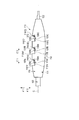
- the width direction of the housing 111 that is substantially perpendicular to (intersects) the longitudinal axis C is defined, and one side of the width direction is defined as the first housing width direction (the direction of the arrow W′1 in FIG. 17). The other side in the width direction is defined as a second housing width direction (direction of arrow W′2 in FIG. 17). Further, one side of the direction substantially perpendicular (crossing) the longitudinal axis C and substantially perpendicular (crossing) the width direction of the housing 111 is defined as a first crossing direction (the direction of arrow A′1 in FIG. 16). The side opposite to the first intersecting direction is defined as a second intersecting direction (the direction of arrow A′2 in FIG. 16). 16 is a view as seen from the first housing width direction, and FIG. 17 is a view as seen from the first intersecting direction (first vertical direction).
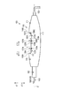
- a groove portion (step forming portion) 138C that is recessed toward the second intersecting direction (second vertical direction) is provided at a portion facing the first intersecting direction.
- the groove portion 138C has a bottom surface (operation button mounting surface) 115A as an exposed surface, and the exposed surface 115 includes a front end side extending portion 116A extending from the step 117 to the front end side C′1, and a step 137C described later.
- a proximal end extending portion 116B extending from the base end to the proximal end C′2.
- the bottom surface 115A is defined between the distal end side extending portion (step forming portion) 116A and the proximal end extending portion (step forming portion) 116B.
- Operation buttons 123A to 123C which are operation members, are attached to the bottom surface 115A of the groove 138C.
- each of the operation buttons 123A to 123C includes an operation surface (one corresponding to 125A to 125C) exposed to the outside of the housing 111 on the exposed surface 115 of the housing 111, and each of the operation buttons 123A to 123C is provided. Then, the operation surface (one corresponding to 125A to 125C) is pressed by the operation input.
- operation switches are provided in the housing 111 so as to correspond to the operation buttons 123A to 123C, and the energy sources correspond to the open / close states of the operation switches. It is detected whether or not an operation input has been performed with an operation button (one corresponding to 123A to 123C).
- an operation input is performed with the operation button 123A, for example, ultrasonic vibration generated in the ultrasonic vibrator by electric power from the energy source is transmitted to the rod treatment unit 106, and high-frequency energy (high-frequency power) is transmitted to the end effector 105. To be supplied.
- the energy source supplies high-frequency energy to the end effector 105 in the coagulation mode
- the energy source is high. High frequency energy is supplied to the end effector 105 in an energy level incision mode.
- the operation surfaces 125A to 125C are positioned on the reference straight line T′1 substantially parallel to the longitudinal axis C.
- the reference straight line T′1 is a virtual line that passes through the groove 138C.
- the operation surface (second operation surface) of the operation button (second operation member) 123B on the proximal side from the operation surface (first operation surface) 125A of the operation button (first operation member) 123A. ) 125B is located, and the operation surface (third operation surface) 125C of the operation button (third operation member) 123C is located closer to the base end side than the operation surface 125B of the operation button 123B.
- protrusions (step forming portions) 135A and 135B protruding in the first intersecting direction are provided.
- the protrusion 135A is located between the first operation surface 125A and the second operation surface 125B in the direction along the longitudinal axis C ′, and the protrusion 135B is aligned with the second operation surface 125B in the direction along the longitudinal axis C ′. It is located between two operation surfaces 125C.
- a step 137A is formed in a state facing the front end side (side closer to the operation surface 125A), and in the protrusion 135B, a step 137B is formed in a state facing the front end side (side closer to the operation surface 125B). Yes. Further, a step 137C is formed on the base end surface of the groove 138C so as to face the distal end side (side close to the operation surface 125C). Each of the steps 137A to 137C is located in the vicinity of the corresponding operation surface (corresponding one of 125A to 125C), and is located on the base end side from the corresponding operation surface (corresponding one of 125A to 125C). Yes.
- the reference straight line T′1 passes through the steps 137A to 137C.
- Each of the steps 137A to 137C may be adjacent to the outer edge of the corresponding operation surface (corresponding one of 125A to 125C) from the base end side as in the first embodiment.
- the proximal side from the outer edge of the corresponding operation surface (corresponding one of 125A to 125C) May be separated from each other.
- each of the protrusions 135A and 135B and the groove 138C forms a step (corresponding one of 137A to 137C) corresponding to the first intersecting direction and the second intersecting direction. That is, each of the steps 137A to 137C is formed in the radial direction with the longitudinal axis C as the center. A portion distal to each longitudinal axis C ′ of the steps 137A to 137C in the radial direction about the longitudinal axis C ′ is the step (137A) of the corresponding operation surface (corresponding one of 125A to 125C).
- the steps 137A to 137C in the first intersecting direction and the second intersecting direction respectively correspond to at least the steps (137A to 137C) at the outer edge of the corresponding operation surface (one corresponding to 125A to 125C).
- the position closest to (one) is lower (longitudinal axis) than the part of the step (corresponding one of 137A to 137C) farther from the corresponding operation surface (corresponding one of 125A to 125C). (Center axis) close to C ′).
- each of the steps 137A to 137C has at least a part of the outer edge of the corresponding operation surface (one corresponding to 125A to 125C) of the step (one corresponding to 137A to 137C). It is set lower than the part far from the corresponding operation surface (one corresponding to 125A to 125C) (adjacent to the longitudinal axis (center axis) C ′).
- FIG. 18 shows a state where the surgeon holds the holding unit 110.
- the medical treatment instrument 100 is a pencil type medical treatment instrument
- the holding unit 110 is held in the same manner as when holding a pencil.
- the thumb F1 is brought into contact with the exposed surface 115 from the first housing width direction W′1, and the middle finger F3 is exposed from the second housing width direction W′2.
- the housing 111 (housing main body 112) is held.
- the thumb F1 extends through a portion of the exposed surface 115 facing the first housing width direction W′1
- the middle finger F3 is a portion of the exposed surface 115 facing the second housing width direction W′2. It extends through.
- the base end portion of the exposed surface 115 (the base end side from the base end of the groove portion 138C) extends from the portion facing the first intersecting direction A′1 to the portion facing the second housing width direction W′2.
- the palm P is in contact.
- the index finger F2 extends through a portion of the exposed surface 115 that faces the first intersecting direction A′1.
- the operation surface (one corresponding to 125A to 125C) is pressed by the index finger F2.
- the ring finger F4 and the little finger F5 are located on the second housing width direction side from the housing 111.
- steps 137A to 137C are formed in the radial direction centered on the longitudinal axis C on the exposed surface 115 of the housing 111.
- Each of the steps 137A to 137C corresponds to the corresponding operation surface (125A to 125C). 1).
- at least a part of the outer edge of the corresponding operation surface corresponds to the operation surface (corresponding one of 137A to 137C) ( It is lower than the portion far from the corresponding one of 125A to 125C (close to the longitudinal axis (center axis) C ′).
- the palm P and the fingers F1 to F5 come into contact with the corresponding operation surface (one corresponding to 125A to 125C) by each of the steps 137A to 137C. It becomes difficult to effectively prevent the operation surfaces 125A to 125C from being pressed by mistake. That is, even when the plurality of operation surfaces 125A to 125C are arranged in parallel on the reference straight line T′1 substantially parallel to the longitudinal axis C, it is possible to effectively prevent the operation surfaces 125A to 125C from being pressed by mistake.
- the index finger F2 is extended through a portion of the exposed surface 115 facing the first crossing direction. Further, the operation surfaces 125A to 125C are located at portions of the exposed surface 115 that face the first intersecting direction. Therefore, by forming the steps 137A to 137C in the first intersecting direction and the second intersecting direction, each of the steps 137A to 137C causes the index finger F2 to correspond to the corresponding operation surface (corresponding 1 of 125A to 125C). Inadvertent contact with the other is more effectively prevented.
- each of the steps 137A to 137C has a position closest to at least the step (corresponding one of 137A to 137C) on the outer edge of the corresponding operation surface (corresponding one of 125A to 125C).
- the step (corresponding one of 137A to 137C) is made lower (longitudinal axis (central axis) C ′) than the part far from the corresponding operation surface (corresponding one of 125A to 125C) In close proximity). For this reason, it is more effectively prevented that the palm P and the fingers F1 to F5 come into contact with the operation surfaces 125A to 125C by mistake.
- each of the steps 137A to 137C is in the vicinity of the corresponding operation surface (corresponding one of 125A to 125C) and the base end of the corresponding operation surface (corresponding one of 125A to 125C). Located on the side. For this reason, the steps 137A to 137C further effectively prevent the palm P and the fingers F1 to F5 from erroneously contacting the operation surfaces 125A to 125C.
- the exposed surface 115 includes a distal end side extending portion (step forming portion) 116′A1 extending from the distal end of the groove portion 138A to the distal end side C′1, and a proximal end of the groove portion 138A to the proximal end side C′2. And a base end side extending portion (step forming portion) 116′A2.
- the exposed surface 115 extends from the distal end of the groove portion 138B to the distal end side, a distal end side extending portion (step forming portion) 116'B1, and the groove portion 138B extends from the proximal end to the proximal end side.
- a proximal end extending portion (step forming portion) 116′B2 has a distal end extending portion (step forming portion) 116′C1 extending from the distal end of the groove portion 138C to the distal end side, and a base of the groove portion 138C. It has a base end side extending portion (step forming portion) 116′C2 extending from the end to the base end side.
- Each of the operation surfaces 125A to 125C is located on the bottom surface (corresponding one of 115′A to 115′C) of the corresponding groove (corresponding one of 138A to 138C). Also in this modification, each of the steps 137A to 137C is in the vicinity of the corresponding operation surface (corresponding one of 125A to 125C) and the base end of the corresponding operation surface (corresponding one of 125A to 125C). Located on the side.
- each of the steps 137A to 137C2 at least a part of the outer edge of the corresponding operation surface (corresponding one of 125A to 125C) corresponds to the operation surface (corresponding one of 137A to 137C) ( 125A to 125C) and lower than the portion far from the region (close to the longitudinal axis (center axis) C ′).
- each operation surface 125C of front end side extension part 116'C1 and proximal end extension part 116'C2 is also more than the operation surface 125C about the radial direction centering on the longitudinal axis C '. It is located at a position far (high) from the longitudinal axis C ′. For this reason, when the medical treatment instrument 100 is arranged on a flat table or the like (not shown) in a state where the first intersecting direction A′1 coincides with the vertically downward direction, the first intersecting direction A′1 of the exposed surface 115 is changed. In the facing portion, the groove portions 138A to 138C and the operation surfaces 125A to 125C do not contact the table.
- the position and number of the operation surfaces (125A to 125C) can be changed as appropriate. That is, at least one operation surface (125A to 125C) is provided on the exposed surface 115 of the housing 111 (housing main body 112) and is in the vicinity of and corresponding to the corresponding operation surface (corresponding one of 125A to 125C). If each of the steps (137A to 137C) in the radial direction around the longitudinal axis C ′ can be formed on the base end side of the operation surface (one corresponding to 125A to 125C), the above-described configuration is used. Applicable.
- the housing (111) of the pencil type medical treatment device (100) has a proximal end and a distal end, and extends along the longitudinal axis (C ′) from the proximal end to the distal end.
- the housing (111) has an exposed surface (115) exposed to the outside in the housing body (112).
- a first operating member (123A) and a second operating member (123B; 123C) are attached to the housing (111), and the first operating member (123A) is exposed to the outside of the housing (111). And a first operation surface (125A) that is pressed by an operation input.
- the second operation member (123B; 123C) includes a second operation surface (125B; 125C) that is exposed to the outside of the housing (111) and is pressed by an operation input.
- the first operation surface (125A) and the second operation surface (125B; 125C) are located on a reference straight line (T′1) substantially parallel to the longitudinal axis (C ′), and the second operation surface (125B ; 125C) is located closer to the base end side than the first operation surface (125A).
- the first operation surface (125A) and the second operation surface (125B) in the vicinity of the first operation surface (125A) on the exposed surface (115) of the housing (111) and on the reference straight line (T′1).
- a step forming portion (135A; 138A) is provided.
- the step forming portion (135A; 138A) has a longitudinal axis (C ′) in a state where the portion closer to the first operation surface (125A) is lower than the portion farther from the first operation surface (125A). ) Is formed in the radial direction centered at).
- the step (137A) makes at least a part of the outer edge of the first operation surface (125A) lower than a portion of the step (137A) far from the first operation surface (125A).
- a pencil-type medical treatment device (100) comprising:
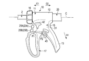
- the cover member 42 is rotatable between a position covering the operation surfaces 25A and 25B from the first housing width direction W1 and a position (position shown in FIG. 20) away from the operation surfaces 25A and 25B to the base end side. is there.
- the operator moves the cover member 42 to a position away from the operation surfaces 25A and 25B to the proximal end side.
- each of operation surface 25A, 25B is pressed.
- the operation surfaces 25A and 25B are covered with the cover member 42 from the first housing width direction W1. This makes it difficult for the operation surfaces 25A and 25B to come into contact with the palm P and the fingers F1 to F5, thereby effectively preventing the operation surfaces 25A and 25B from being pressed by mistake.
- the cover member 43 is attached to the exposed surface 115 of the housing 11 so as to be rotatable about the rotation axis P2.
- the cover member 42 is attached to the first housing surface 31 facing the first housing width direction W1.
- the rotation axis P2 is substantially parallel to the width direction of the housing 11 (the first housing width direction W1 and the second housing width direction W2).
- the cover member 43 is rotatable between a position covering the operation surface 25C and a position not covering the operation surface 25C (position shown in FIG. 20) from the first housing width direction W1.
- the operation surface 25C When no operation input is performed, the operation surface 25C is covered with the cover member 43 from the first housing width direction W1. This makes it difficult for the operation surface 25C to come into contact with the palm P and the fingers F1 to F5, thereby effectively preventing the operation surface 25C from being pressed by mistake.
- a cover member 45 is attached to the first housing surface 31 instead of the cover member 43.
- the cover member 45 is rotatable about a rotation axis P3 that is substantially parallel to the surface of the first housing.
- the cover member 45 can rotate between a position covering the operation surface 25C and a position not covering the operation surface 25C (position shown in FIG. 21) from the first housing width direction W1.
- the operation surface 25 ⁇ / b> C is covered with the cover member 43 from the first housing width direction W ⁇ b> 1 when no operation input is performed.
- the first housing width direction W1 is perpendicular to the paper surface
- the second housing width direction W2 is perpendicular to the paper surface
- the cover member (42, 43; 42, 45) configuration of the first reference example and the second reference example described above is the operation surface of the operation member (123A to 123C) provided in the pencil type medical treatment instrument (100). (125A to 125C) is also applicable.
Landscapes
- Health & Medical Sciences (AREA)
- Life Sciences & Earth Sciences (AREA)
- Surgery (AREA)
- Engineering & Computer Science (AREA)
- Medical Informatics (AREA)
- General Health & Medical Sciences (AREA)
- Biomedical Technology (AREA)
- Heart & Thoracic Surgery (AREA)
- Nuclear Medicine, Radiotherapy & Molecular Imaging (AREA)
- Molecular Biology (AREA)
- Animal Behavior & Ethology (AREA)
- Veterinary Medicine (AREA)
- Public Health (AREA)
- Otolaryngology (AREA)
- Physics & Mathematics (AREA)
- Plasma & Fusion (AREA)
- Surgical Instruments (AREA)
- Endoscopes (AREA)
Abstract
L'invention concerne un élément opératoire monté au boîtier d'un instrument de traitement médical et pourvu d'une surface opératoire exposée à l'extérieur du boîtier et poussée par une entrée opérationnelle. Une section de formation de partie étagée est formée sur la surface exposée du boîtier au niveau d'une position proche de la surface opératoire. La section de formation de partie étagée forme une partie étagée dans le sens de la largeur du boîtier de sorte que la portion de la section de formation de partie étagée, située à proximité de la surface opératoire, ait une hauteur inférieure à celle de la portion de la section de formation de partie étagée éloignée de la surface opératoire. À cause de la partie étagée, au moins une partie du bord extérieur de la surface opératoire présente une hauteur inférieure à celle de la portion de la partie étagée éloignée de la surface opératoire.
Priority Applications (1)
| Application Number | Priority Date | Filing Date | Title |
|---|---|---|---|
| JP2016575601A JPWO2016152306A1 (ja) | 2015-03-24 | 2016-02-12 | 医療処置具 |
Applications Claiming Priority (2)
| Application Number | Priority Date | Filing Date | Title |
|---|---|---|---|
| JP2015061014 | 2015-03-24 | ||
| JP2015-061014 | 2015-03-24 |
Publications (1)
| Publication Number | Publication Date |
|---|---|
| WO2016152306A1 true WO2016152306A1 (fr) | 2016-09-29 |
Family
ID=56978803
Family Applications (1)
| Application Number | Title | Priority Date | Filing Date |
|---|---|---|---|
| PCT/JP2016/054120 Ceased WO2016152306A1 (fr) | 2015-03-24 | 2016-02-12 | Instrument de traitement médical |
Country Status (2)
| Country | Link |
|---|---|
| JP (1) | JPWO2016152306A1 (fr) |
| WO (1) | WO2016152306A1 (fr) |
Cited By (1)
| Publication number | Priority date | Publication date | Assignee | Title |
|---|---|---|---|---|
| WO2018104995A1 (fr) * | 2016-12-05 | 2018-06-14 | オリンパス株式会社 | Outil de traitement |
Citations (11)
| Publication number | Priority date | Publication date | Assignee | Title |
|---|---|---|---|---|
| JPH09122141A (ja) * | 1995-10-31 | 1997-05-13 | Semuko:Kk | 電気手術装置用メスホルダ |
| JP2000135222A (ja) * | 1998-08-27 | 2000-05-16 | Olympus Optical Co Ltd | 高周波処置装置 |
| JP2008515562A (ja) * | 2004-10-08 | 2008-05-15 | エシコン・エンド−サージェリィ・インコーポレイテッド | 超音波手術器具 |
| JP2009050704A (ja) * | 2007-08-24 | 2009-03-12 | Olympus Medical Systems Corp | 外科用の手術装置 |
| JP2009261911A (ja) * | 2008-04-28 | 2009-11-12 | Olympus Medical Systems Corp | 外科手術装置 |
| JP2010227555A (ja) * | 2009-03-04 | 2010-10-14 | Terumo Corp | 医療用マニピュレータ |
| JP2010540186A (ja) * | 2007-10-05 | 2010-12-24 | エシコン・エンド−サージェリィ・インコーポレイテッド | 人間工学的外科用器具 |
| WO2012074013A1 (fr) * | 2010-12-01 | 2012-06-07 | オリンパスメディカルシステムズ株式会社 | Endoscope |
| JP5165163B2 (ja) * | 2011-03-24 | 2013-03-21 | オリンパスメディカルシステムズ株式会社 | 把持処置装置 |
| WO2013062103A1 (fr) * | 2011-10-26 | 2013-05-02 | オリンパスメディカルシステムズ株式会社 | Instrument de traitement à ultrasons |
| US20150076210A1 (en) * | 2013-08-23 | 2015-03-19 | Ethicon Endo-Surgery, Inc. | Torque optimization for surgical instruments |
-
2016
- 2016-02-12 WO PCT/JP2016/054120 patent/WO2016152306A1/fr not_active Ceased
- 2016-02-12 JP JP2016575601A patent/JPWO2016152306A1/ja active Pending
Patent Citations (11)
| Publication number | Priority date | Publication date | Assignee | Title |
|---|---|---|---|---|
| JPH09122141A (ja) * | 1995-10-31 | 1997-05-13 | Semuko:Kk | 電気手術装置用メスホルダ |
| JP2000135222A (ja) * | 1998-08-27 | 2000-05-16 | Olympus Optical Co Ltd | 高周波処置装置 |
| JP2008515562A (ja) * | 2004-10-08 | 2008-05-15 | エシコン・エンド−サージェリィ・インコーポレイテッド | 超音波手術器具 |
| JP2009050704A (ja) * | 2007-08-24 | 2009-03-12 | Olympus Medical Systems Corp | 外科用の手術装置 |
| JP2010540186A (ja) * | 2007-10-05 | 2010-12-24 | エシコン・エンド−サージェリィ・インコーポレイテッド | 人間工学的外科用器具 |
| JP2009261911A (ja) * | 2008-04-28 | 2009-11-12 | Olympus Medical Systems Corp | 外科手術装置 |
| JP2010227555A (ja) * | 2009-03-04 | 2010-10-14 | Terumo Corp | 医療用マニピュレータ |
| WO2012074013A1 (fr) * | 2010-12-01 | 2012-06-07 | オリンパスメディカルシステムズ株式会社 | Endoscope |
| JP5165163B2 (ja) * | 2011-03-24 | 2013-03-21 | オリンパスメディカルシステムズ株式会社 | 把持処置装置 |
| WO2013062103A1 (fr) * | 2011-10-26 | 2013-05-02 | オリンパスメディカルシステムズ株式会社 | Instrument de traitement à ultrasons |
| US20150076210A1 (en) * | 2013-08-23 | 2015-03-19 | Ethicon Endo-Surgery, Inc. | Torque optimization for surgical instruments |
Cited By (4)
| Publication number | Priority date | Publication date | Assignee | Title |
|---|---|---|---|---|
| WO2018104995A1 (fr) * | 2016-12-05 | 2018-06-14 | オリンパス株式会社 | Outil de traitement |
| CN110049737A (zh) * | 2016-12-05 | 2019-07-23 | 奥林巴斯株式会社 | 处置器具 |
| JPWO2018104995A1 (ja) * | 2016-12-05 | 2019-08-08 | オリンパス株式会社 | 処置具 |
| CN110049737B (zh) * | 2016-12-05 | 2022-06-14 | 奥林巴斯株式会社 | 处置器具 |
Also Published As
| Publication number | Publication date |
|---|---|
| JPWO2016152306A1 (ja) | 2017-04-27 |
Similar Documents
| Publication | Publication Date | Title |
|---|---|---|
| US20260020877A1 (en) | Surgical instrument | |
| JP5583865B2 (ja) | 超音波処置具 | |
| CN101371797B (zh) | 外科用手术装置 | |
| EP2589347A1 (fr) | Dispositif chirurgical de préhension | |
| CN104010584A (zh) | 把持处理装置 | |
| US20150327918A1 (en) | Treatment instrument | |
| JP6177491B2 (ja) | 内視鏡 | |
| CN106999228A (zh) | 把持处置单元 | |
| JPWO2016152306A1 (ja) | 医療処置具 | |
| US20170128095A1 (en) | Treatment instrument | |
| CN109692028B (zh) | 一种超声手术器械 | |
| CN108289701A (zh) | 能量处置器具 | |
| CN107920835A (zh) | 钳子型处置器具 | |
| JP6223649B1 (ja) | 医療機器、医療機器システム | |
| CN109416995A (zh) | 电子开关机构 | |
| US20190350643A1 (en) | Surgical device | |
| JP6084349B1 (ja) | 超音波処置具 | |
| US11195676B2 (en) | Electronic switch mechanism | |
| CN110049737B (zh) | 处置器具 | |
| JP2006340839A (ja) | 超音波処置用スイッチ装置および医療機器用スイッチ装着システム | |
| JPH11332871A (ja) | 内視鏡下外科手術用処置具 | |
| GB2428283A (en) | A tool with a switch encircling a handpiece | |
| WO2016075745A1 (fr) | Appareil de traitement médical |
Legal Events
| Date | Code | Title | Description |
|---|---|---|---|
| 121 | Ep: the epo has been informed by wipo that ep was designated in this application |
Ref document number: 16768209 Country of ref document: EP Kind code of ref document: A1 |
|
| ENP | Entry into the national phase |
Ref document number: 2016575601 Country of ref document: JP Kind code of ref document: A |
|
| NENP | Non-entry into the national phase |
Ref country code: DE |
|
| 122 | Ep: pct application non-entry in european phase |
Ref document number: 16768209 Country of ref document: EP Kind code of ref document: A1 |