WO2016152668A1 - 中空スタビライザ - Google Patents
中空スタビライザ Download PDFInfo
- Publication number
- WO2016152668A1 WO2016152668A1 PCT/JP2016/058278 JP2016058278W WO2016152668A1 WO 2016152668 A1 WO2016152668 A1 WO 2016152668A1 JP 2016058278 W JP2016058278 W JP 2016058278W WO 2016152668 A1 WO2016152668 A1 WO 2016152668A1
- Authority
- WO
- WIPO (PCT)
- Prior art keywords
- hollow
- quenching
- hollow stabilizer
- bending
- stabilizer
- Prior art date
- Legal status (The legal status is an assumption and is not a legal conclusion. Google has not performed a legal analysis and makes no representation as to the accuracy of the status listed.)
- Ceased
Links
Images









Classifications
-
- B—PERFORMING OPERATIONS; TRANSPORTING
- B60—VEHICLES IN GENERAL
- B60G—VEHICLE SUSPENSION ARRANGEMENTS
- B60G21/00—Interconnection systems for two or more resiliently-suspended wheels, e.g. for stabilising a vehicle body with respect to acceleration, deceleration or centrifugal forces
- B60G21/02—Interconnection systems for two or more resiliently-suspended wheels, e.g. for stabilising a vehicle body with respect to acceleration, deceleration or centrifugal forces permanently interconnected
- B60G21/04—Interconnection systems for two or more resiliently-suspended wheels, e.g. for stabilising a vehicle body with respect to acceleration, deceleration or centrifugal forces permanently interconnected mechanically
- B60G21/05—Interconnection systems for two or more resiliently-suspended wheels, e.g. for stabilising a vehicle body with respect to acceleration, deceleration or centrifugal forces permanently interconnected mechanically between wheels on the same axle but on different sides of the vehicle, i.e. the left and right wheel suspensions being interconnected
- B60G21/055—Stabiliser bars
-
- B—PERFORMING OPERATIONS; TRANSPORTING
- B21—MECHANICAL METAL-WORKING WITHOUT ESSENTIALLY REMOVING MATERIAL; PUNCHING METAL
- B21D—WORKING OR PROCESSING OF SHEET METAL OR METAL TUBES, RODS OR PROFILES WITHOUT ESSENTIALLY REMOVING MATERIAL; PUNCHING METAL
- B21D53/00—Making other particular articles
- B21D53/88—Making other particular articles other parts for vehicles, e.g. cowlings, mudguards
-
- B—PERFORMING OPERATIONS; TRANSPORTING
- B21—MECHANICAL METAL-WORKING WITHOUT ESSENTIALLY REMOVING MATERIAL; PUNCHING METAL
- B21D—WORKING OR PROCESSING OF SHEET METAL OR METAL TUBES, RODS OR PROFILES WITHOUT ESSENTIALLY REMOVING MATERIAL; PUNCHING METAL
- B21D7/00—Bending rods, profiles, or tubes
- B21D7/16—Auxiliary equipment, e.g. for heating or cooling of bends
- B21D7/165—Cooling equipment
-
- C—CHEMISTRY; METALLURGY
- C21—METALLURGY OF IRON
- C21D—MODIFYING THE PHYSICAL STRUCTURE OF FERROUS METALS; GENERAL DEVICES FOR HEAT TREATMENT OF FERROUS OR NON-FERROUS METALS OR ALLOYS; MAKING METAL MALLEABLE, e.g. BY DECARBURISATION OR TEMPERING
- C21D1/00—General methods or devices for heat treatment, e.g. annealing, hardening, quenching or tempering
- C21D1/18—Hardening; Quenching with or without subsequent tempering
-
- C—CHEMISTRY; METALLURGY
- C21—METALLURGY OF IRON
- C21D—MODIFYING THE PHYSICAL STRUCTURE OF FERROUS METALS; GENERAL DEVICES FOR HEAT TREATMENT OF FERROUS OR NON-FERROUS METALS OR ALLOYS; MAKING METAL MALLEABLE, e.g. BY DECARBURISATION OR TEMPERING
- C21D1/00—General methods or devices for heat treatment, e.g. annealing, hardening, quenching or tempering
- C21D1/62—Quenching devices
- C21D1/667—Quenching devices for spray quenching
-
- C—CHEMISTRY; METALLURGY
- C21—METALLURGY OF IRON
- C21D—MODIFYING THE PHYSICAL STRUCTURE OF FERROUS METALS; GENERAL DEVICES FOR HEAT TREATMENT OF FERROUS OR NON-FERROUS METALS OR ALLOYS; MAKING METAL MALLEABLE, e.g. BY DECARBURISATION OR TEMPERING
- C21D9/00—Heat treatment, e.g. annealing, hardening, quenching or tempering, adapted for particular articles; Furnaces therefor
- C21D9/08—Heat treatment, e.g. annealing, hardening, quenching or tempering, adapted for particular articles; Furnaces therefor for tubular bodies or pipes
-
- C—CHEMISTRY; METALLURGY
- C21—METALLURGY OF IRON
- C21D—MODIFYING THE PHYSICAL STRUCTURE OF FERROUS METALS; GENERAL DEVICES FOR HEAT TREATMENT OF FERROUS OR NON-FERROUS METALS OR ALLOYS; MAKING METAL MALLEABLE, e.g. BY DECARBURISATION OR TEMPERING
- C21D9/00—Heat treatment, e.g. annealing, hardening, quenching or tempering, adapted for particular articles; Furnaces therefor
- C21D9/08—Heat treatment, e.g. annealing, hardening, quenching or tempering, adapted for particular articles; Furnaces therefor for tubular bodies or pipes
- C21D9/085—Cooling or quenching
-
- B—PERFORMING OPERATIONS; TRANSPORTING
- B60—VEHICLES IN GENERAL
- B60G—VEHICLE SUSPENSION ARRANGEMENTS
- B60G2206/00—Indexing codes related to the manufacturing of suspensions: constructional features, the materials used, procedures or tools
- B60G2206/01—Constructional features of suspension elements, e.g. arms, dampers, springs
- B60G2206/012—Hollow or tubular elements
-
- B—PERFORMING OPERATIONS; TRANSPORTING
- B60—VEHICLES IN GENERAL
- B60G—VEHICLE SUSPENSION ARRANGEMENTS
- B60G2206/00—Indexing codes related to the manufacturing of suspensions: constructional features, the materials used, procedures or tools
- B60G2206/01—Constructional features of suspension elements, e.g. arms, dampers, springs
- B60G2206/40—Constructional features of dampers and/or springs
- B60G2206/42—Springs
- B60G2206/427—Stabiliser bars or tubes
-
- B—PERFORMING OPERATIONS; TRANSPORTING
- B60—VEHICLES IN GENERAL
- B60G—VEHICLE SUSPENSION ARRANGEMENTS
- B60G2206/00—Indexing codes related to the manufacturing of suspensions: constructional features, the materials used, procedures or tools
- B60G2206/01—Constructional features of suspension elements, e.g. arms, dampers, springs
- B60G2206/70—Materials used in suspensions
- B60G2206/72—Steel
-
- B—PERFORMING OPERATIONS; TRANSPORTING
- B60—VEHICLES IN GENERAL
- B60G—VEHICLE SUSPENSION ARRANGEMENTS
- B60G2206/00—Indexing codes related to the manufacturing of suspensions: constructional features, the materials used, procedures or tools
- B60G2206/01—Constructional features of suspension elements, e.g. arms, dampers, springs
- B60G2206/70—Materials used in suspensions
- B60G2206/72—Steel
- B60G2206/724—Wires, bars or the like
-
- B—PERFORMING OPERATIONS; TRANSPORTING
- B60—VEHICLES IN GENERAL
- B60G—VEHICLE SUSPENSION ARRANGEMENTS
- B60G2206/00—Indexing codes related to the manufacturing of suspensions: constructional features, the materials used, procedures or tools
- B60G2206/01—Constructional features of suspension elements, e.g. arms, dampers, springs
- B60G2206/80—Manufacturing procedures
- B60G2206/81—Shaping
-
- B—PERFORMING OPERATIONS; TRANSPORTING
- B60—VEHICLES IN GENERAL
- B60G—VEHICLE SUSPENSION ARRANGEMENTS
- B60G2206/00—Indexing codes related to the manufacturing of suspensions: constructional features, the materials used, procedures or tools
- B60G2206/01—Constructional features of suspension elements, e.g. arms, dampers, springs
- B60G2206/80—Manufacturing procedures
- B60G2206/84—Hardening
- B60G2206/8402—Quenching
-
- B—PERFORMING OPERATIONS; TRANSPORTING
- B60—VEHICLES IN GENERAL
- B60G—VEHICLE SUSPENSION ARRANGEMENTS
- B60G2600/00—Indexing codes relating to particular elements, systems or processes used on suspension systems or suspension control systems
- B60G2600/72—Cooling or warming means
-
- C—CHEMISTRY; METALLURGY
- C21—METALLURGY OF IRON
- C21D—MODIFYING THE PHYSICAL STRUCTURE OF FERROUS METALS; GENERAL DEVICES FOR HEAT TREATMENT OF FERROUS OR NON-FERROUS METALS OR ALLOYS; MAKING METAL MALLEABLE, e.g. BY DECARBURISATION OR TEMPERING
- C21D2221/00—Treating localised areas of an article
- C21D2221/10—Differential treatment of inner with respect to outer regions, e.g. core and periphery, respectively
Definitions
- the present invention relates to a hollow stabilizer having a hollow structure.
- Vehicles such as automobiles are provided with a stabilizer (stabilizer bar or anti-roll bar) that suppresses the roll of the vehicle body due to the vertical shift of the wheels.
- the stabilizer generally includes a torsion portion that extends in the vehicle width direction and a pair of left and right arm portions that are bent toward the front and rear direction of the vehicle, and includes a substantially U-shaped rod.
- the stabilizer In a vehicle, the stabilizer is in a state of being suspended between the left and right suspension devices by connecting the tip of each arm portion to a wheel suspension device and inserting the torsion portion into a bush fixed to the vehicle body side. Supported.
- the solid stabilizer has features such as excellent mechanical strength and low manufacturing cost.
- the hollow stabilizer is in a form suitable for reducing the weight of the vehicle, although it is not easy to ensure the mechanical strength as compared with the solid stabilizer.
- a material for the hollow stabilizer an electric resistance welded steel pipe, a seamless steel pipe, a forged steel pipe or the like is generally used.
- ERW steel pipe is frequently used as a material for a hollow stabilizer because of its low manufacturing cost and excellent mass productivity.
- carbon steel such as S48C (JIS standard)
- spring steel such as SUP9 (JIS standard) and SUP9A (JIS standard)
- the hollow stabilizer is often manufactured by subjecting a spring steel pipe to bending to form a product shape and then subjecting it to a heat treatment.
- a cold bending process performed using an NC bender, a hot bending process performed using a total bending mold, and the like are performed according to the thickness and diameter of the steel pipe.
- the heat treatment a quenching process and a tempering process are performed, and the quenching method is mainly oil quenching.
- the heat-treated raw tube is usually made into a product through a finishing process such as a surface processing process by shot peening or a coating process.
- Patent Document 1 discloses an ERW welded steel pipe in which an ERW welded steel pipe for hollow stabilizers having a thickness ratio of thickness t to outer diameter D of t / D ⁇ 20% is reduced in diameter after ERW welding. It is described that it is realized by adopting.
- Patent Document 2 discloses a technique for obtaining the durability of a stabilizer, in which an electric resistance welded tube is contracted in a hot or warm temperature range so that the ratio of the plate thickness to the outer diameter is 18 to 35%.
- a hollow stabilizer manufacturing method is disclosed, in which a contracted ERW tube is formed into a stabilizer shape, and a heat treatment step, shot peening, and coating are performed.
- the hollow stabilizer has a hollow structure, the section modulus is low, the bending stiffness (EI) is lowered, and the strength is disadvantageous compared to a solid stabilizer with a solid structure.
- the hollow stabilizer having a hollow structure is lightweight, but since it is hollow, the section modulus is reduced and the strength is reduced as compared with a solid stabilizer having a solid structure.
- the bending portion of the hollow stabilizer has a concave shape in the case of energization heating at the time of quenching, so that the current density is high and local high temperature may occur. Also, during cooling, the bent portion is concave, so the cooling rate tends to be low. For this reason, the bent portion may be insufficiently quenched, resulting in a decrease in hardness.
- the bending portion of the hollow stabilizer is a portion where both a large bending stress and a torsional stress are generated, and the stress is high. For this reason, the bent portion is the most desired part for improving the strength and fatigue strength (durability) of the hollow stabilizer. Therefore, when the thickness of the hollow stabilizer is increased, quenching is further insufficient.
- a solid stabilizer having a solid structure has a high section modulus and a high strength, but has a drawback of increasing weight.
- the present invention was conceived in view of the above circumstances, and an object thereof is to provide a lightweight hollow stabilizer having high strength with improved hardness of a bent portion.
- a hollow stabilizer according to claim 1 of the present invention is provided in a vehicle, and a torsion portion extending in the vehicle width direction, an arm portion extending in the front-rear direction of the vehicle, the torsion portion and the arm A tubular hollow stabilizer having a bending portion for connecting the bending portion, wherein the hardness of the bending inner surface of the bending portion is 70% or more with respect to the hardness of the outer surface of the arm portion.
- the hollow stabilizer of the first aspect of the present invention since the hardness of the outer surface of the bending portion inside the bending portion is 70% or more with respect to the hardness of the outer surface of the arm portion, a hollow stabilizer having high fatigue durability can be obtained.
- a hollow stabilizer according to claim 2 of the present invention is provided in a vehicle, and includes a torsion portion extending in the vehicle width direction, an arm portion extending in the front-rear direction of the vehicle, and a bending portion connecting the torsion portion and the arm portion.
- the bending portion is subjected to a treatment for increasing the hardness locally or from the inner surface side.
- the bending portion is subjected to a treatment for increasing the hardness locally or from the inner surface side, the fatigue failure at the bending portion is suppressed by improving the hardness of the bending portion. it can.
- a hollow stabilizer according to claim 6 of the present invention is provided in a vehicle, and includes a torsion portion extending in the vehicle width direction, an arm portion extending in the front-rear direction of the vehicle, and a bending portion connecting the torsion portion and the arm portion.
- a hollow hollow stabilizer provided with a quenching agent in which a coolant is injected to the outer surface of the bent portion on the inner side of the bend.
- the quenching in which the coolant is sprayed is applied to the outer surface of the bent portion inside the bent portion, the hardness of the bent portion is improved and the fatigue failure at the bent portion is achieved. Can be suppressed.
- a hollow stabilizer according to an eighth aspect of the present invention is provided in a vehicle and includes a torsion portion extending in the vehicle width direction, an arm portion extending in the front-rear direction of the vehicle, and a bending portion connecting the torsion portion and the arm portion.
- a hollow hollow stabilizer provided with a quenching agent in which a coolant is injected into the hollow stabilizer.
- the hollow stabilizer of the eighth aspect of the present invention since the quenching in which the coolant is injected into the hollow stabilizer is performed, the hardness inside the bending portion of the bending portion can be increased, and fatigue failure can be suppressed.
- Process drawing which shows the manufacturing method of the hollow stabilizer which concerns on embodiment of this invention.
- the top view which shows the state which carries out the water quenching of the hollow pipe base pipe formed by bending.
- the perspective schematic diagram seen from the diagonally upward direction which shows the state which rocks the hollow pipe raw tube to which the bending process was given when water quenching.
- the top view which shows the state which has quenched the inner side of the bending part of the hollow pipe element pipe
- the figure which shows the effect by an outer surface jet by hardness Steel type C formed at a temperature of about 900 ° C. to about 1200 ° C. is tempered at a tempering temperature of 350 ° C., and steel type D formed at a temperature of about 900 ° C. to about 1200 ° C. is tempered at a tempering temperature of 350 ° C. and 400 ° C. , SN diagram comparing durability.
- the SN diagram which compared the tempering temperature of 250 degreeC and 300 degreeC of the steel grade D of shaping
- the top view which shows the state which is quenching locally from the inner surface by the hollow pipe element pipe
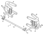
- FIG. 1A is a perspective view of a hollow stabilizer according to an embodiment of the present invention connected to a suspension device provided in a vehicle.
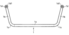
- FIG. 1B is a plan view of a hollow stabilizer according to an embodiment of the present invention connected to a suspension device provided in a vehicle.
- the hollow stabilizer 1 is a tubular stabilizer formed using a hollow steel pipe or the like.
- the hollow stabilizer 1 includes a torsion portion 1a extending in the vehicle width direction and a pair of left and right arm portions 1b, 1b extending in the vehicle front-rear direction.
- the hollow stabilizer 1 is bent at bent portions 1c and 1c (indicated by broken lines in FIG. 1B) symmetrically positioned at both ends of a torsion portion 1a extending in the vehicle width direction, and is connected to a pair of left and right arm portions 1b and 1b. It has a U-shape. In addition, it is good also as a structure which has the bending part 1c two or more places.
- the hollow stabilizer 1 has an outer diameter D of the torsion part 1a of about 10 mm to about 43 mm, and a plate thickness t of about 2 mm to about 10 mm. T / D described later indicates the above (plate thickness t / outer diameter D).
- each arm part 1b, 1b there is a flat plate-like connecting part (eyeball part) 1d, 1d serving as an attaching part.
- the connecting portions (eyeball portions) 1d and 1d are formed in a flat plate shape (flat shape) having mounting holes 1d1 and 1d1 by pressing.
- the connecting portions 1d and 1d at the distal ends of the arm portions 1b and 1b are connected to a pair of left and right suspension devices 3 and 3 fixed to a vehicle body (not shown) via stabilizer links 2 and 2, respectively.
- a wheel (not shown) is attached to the axle portion 3 a of each suspension device 3.
- the suspension device 3 has a compression spring and an oil damper, and works to attenuate and transmit shocks, vibrations, and the like from the wheels to the vehicle body by being attenuated by internal friction and viscous resistance.
- the torsion part 1 a is inserted into a rubber bush 4 fixed to a cross member (not shown) of the vehicle body and is suspended between the left and right suspension devices 3 and 3.
- a load due to displacement is transmitted from each suspension device 3 and 3 to each arm portion 1b and 1b, and the torsion portion 1a is Torsional deformation.
- an elastic force is generated in the torsion portion 1a so as to restore the torsional deformation.
- the hollow stabilizer 1 suppresses the left-right inclination of the vehicle body by the elastic force against the torsional deformation, thereby increasing the roll rigidity and stabilizing the traveling of the vehicle.
- the hollow stabilizer 1 is made of manganese boron steel.
- FIG. 2A is a cross-sectional view showing an electric resistance welded tube
- FIG. 2B is a cross-sectional view showing an SR tube.
- An electric resistance welded tube is a hot-rolled steel plate formed into a pipe shape by a roll, and the edge in the short direction, which is the joint in the longitudinal direction of the pipe, is joined by electric resistance welding.
- the outer bead gb at the joint of the pipe shown in FIG. 2A is functionally obstructed and is removed by cutting.
- SR pipe has a large diameter ERW pipe and is heated by high frequency. Then, it is thickened to a small-diameter pipe by molding by hot drawing, so that a thick-walled small-diameter pipe is manufactured (see FIG. 2B).
- an electric resistance sewing tube is used for the hollow stabilizer 1 having an outer diameter of about 12 mm to about 44 mm and a plate thickness t of about 2 mm to about 6.5 mm.
- An SR tube is used for the hollow stabilizer 1 having an outer diameter of about 12 mm to about 44 mm and a plate thickness t of about 2 mm to about 10 mm.
- the hollow stabilizer 1 in order to achieve uniform mechanical properties up to the deep part, it is desirable to make the quenching depth sufficiently deep and to convert the main phase of the metal structure to martensite with high hardness up to the central part of the cross section. It is.
- the hollow stabilizer 1 is formed of a metal structure whose main phase is martensite by performing quenching with cooling including immersion in a coolant, injection of coolant, and injection as described later.
- the tensile stress remains in the hollow stabilizer 1, the generation and propagation of a crack are promoted by an external force, a repeated load, etc., and it is easy to break early.
- the hollow stabilizer 1 has a compressive residual stress
- the lifetime can be extended by a crack suppressing effect that acts in a direction in which the compressive residual stress cancels a tensile load such as an external force or a repeated load.
- the residual stress has a close relationship with the life of the metal material, and the influence becomes remarkable particularly in metal fatigue in which a crack gradually develops due to repeated loading.
- compressive residual stress is applied to the surface layer of the base body of the hollow stabilizer 1.
- compressive residual stress due to thermal stress and tensile residual stress due to transformation stress are generated. From these balances, the surface residual stress shows a predetermined distribution. In the vicinity of the surface of the hollow pipe, the thermal stress generated by water quenching is predominantly compressive residual stress.
- a quenching condition with a fast cooling rate suitable for generating the thermal stress.
- a compressive residual stress of a certain value or more exists at a certain depth or more that does not reach the depth of the corrosion pit, which is a factor related to corrosion durability.
- the hollow stabilizer 1 may not be completely quenched inside the bent portions 1c and 1c (see FIGS. 1A and 1B). This is because when cooling is performed, the cooling rate is lowered due to thickening and the difficulty of hitting water in terms of shape. When quenching does not completely occur, the durability of the hollow stabilizer 1 is adversely affected. Therefore, in the present hollow stabilizer 1, in addition to normal water quenching, local quenching by a jet water flow described later is complementarily performed.
- the hollow stabilizer 1 has a metal structure whose main phase is martensite. More specifically, at least 90% or more of the metal structure of the hollow stabilizer 1 has a martensite structure.
- the metal structure of the hollow stabilizer 1 is a martensite structure, static strength, durability strength, fatigue characteristics and the like can be improved. Moreover, since it is a single phase, it becomes difficult to form a local battery in a metal structure, and corrosion resistance can be improved.
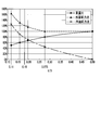
- FIG. 3 shows a comparison between a solid stabilizer and a hollow stabilizer of an equivalent size in terms of weight, outer surface stress, and inner surface stress.
- the horizontal axis represents t (plate thickness) / D (outer diameter), and the vertical axis represents weight (solid line), outer surface stress (dashed line), and inner surface stress (dashed line).
- FIG. 3 shows how the weight, outer surface stress, and inner surface stress change in the hollow stabilizer, assuming that the solid stabilizer is 100%. Therefore, the weight and the external stress of the solid stabilizer are 100%. Since the solid stabilizer has no internal surface and no internal stress is generated, the internal stress is 0%.
- the weight is 100% for the solid stabilizer, and as the t / D decreases (the thickness t decreases), the change in the thickness t is a change in the diameter, so the weight ratio decreases as a quadratic function. .
- the solid stabilizer is changed to a hollow stabilizer in which t / D is reduced, the cross-sectional area is reduced, so that the outer surface stress and the inner surface stress tend to increase.
- the internal stress is 0% for the solid stabilizer, and the internal stress increases as the cross-sectional area decreases as t (plate thickness) decreases (t / D decreases).
- the change in the internal stress when t / D is about 0.275 or less is larger than the external stress.
- t / D is about 0.18 or less, fatigue failure occurs from the inner surface.
- t / D about 0.18 or less, both the internal stress and the external stress rise rapidly. Therefore, when t / D is about 0.18 or less, it is more important to improve the hardness of the inner surface.
- both the inner surface stress and the outer surface stress are rapidly increased, so that it is necessary to improve the hardness on the inner surface side and the outer surface side.
- FIG. 4 is a process diagram showing a method for manufacturing a hollow stabilizer according to an embodiment of the present invention.
- the stabilizer manufacturing method shown in FIG. 4 includes a forming step S10, a quenching step S20, a tempering step S30, a tube end processing step S40, a surface processing step S50, and a coating step S60.
- manganese boron steel is used as the material of the hollow stabilizer 1.
- the material is a tubular hollow pipe material.
- the length and diameter of the hollow pipe material can be set to appropriate dimensions according to the desired product shape.
- the outer diameter of the torsion part 1a is in the range of about 12 mm to about 44 mm, and the plate thickness t is in the range of about 2 mm to about 6.5 mm.
- t / D 0.09 to 0.22.
- the outer diameter of the torsion part 1a is about 12 mm to about 44 mm, and the plate thickness t is about 2 mm to about 10 mm.
- t / D 0.12 to about 0.31.
- hollow pipe material for example, a hot rolled steel material is used.
- the above-mentioned electric resistance welded tube, SR tube, and the like are manufactured using the hot-rolled steel material described above.
- a hollow pipe base tube 1S such as an electric sewing tube or an SR tube for manufacturing the hollow stabilizer 1 having a predetermined length is prepared.
- the forming step S10 is a step in which the hollow pipe base tube 1S is heat-treated in order to bend, and is bent at about 900 ° C. or more and about 1200 ° C. or less to be formed close to the product shape.
- a heating method an appropriate method such as heating with a heating furnace, energization heating, high-frequency induction heating, or the like can be used.
- the electric heating can heat the hollow pipe base tube 1S while suppressing decarburization and deboronation by rapid heating. Therefore, it is preferable to use current heating.
- the hollow pipe base tube 1S is heated to about 900 ° C. or more and about 1200 ° C. or less, and the hollow pipe base tube 1S is bent by molding. Molding at about 900 ° C. or higher is easy to process because it is performed at a high temperature above the recrystallization temperature of the metal.
- the bending may be performed at about 720 ° C. or less. When bending at about 720 ° C. or lower, unlike metal molding at about 900 ° C. or higher and about 1200 ° C. or lower, bending is performed in a state where the metal is not soft. is there.
- the heating temperature is lower than the recrystallization temperature of the metal, and the metal is not soft. Therefore, for example, the interval between the bends needs to be about 1 time or more of the outer diameter.
- the bending process is performed at a heating temperature equal to or higher than the recrystallization temperature of the metal, the metal is soft and the interval between the bendings is about half that of bending by the vendor.
- the mold forming is easy to process.
- the molding at about 900 ° C. or more and about 1200 ° C. or less has high productivity.
- the mass productivity is more than double that of bending by a vendor.
- the bending process can be performed at a plurality of locations so that a plurality of bent portions 1c are formed according to a desired product shape. That is, a plurality of bent portions 1c, torsion portions 1a, and arm portions 1b can be formed by multistage bending by molding.
- the quenching step S20 is a step of heating the bent hollow pipe blank 1S to a high temperature (about 900 ° C. or higher) and cooling it with a coolant.
- a coolant a medium having a heat transfer coefficient equivalent to or close to that of water is used. That is, the quenching step S40 is a step of heating and quenching the hollow pipe base tube 1S that has been subjected to the bending process, followed by cooling at a lower critical cooling rate or higher.
- the heat transfer coefficient of the coolant is preferably within a range of ⁇ 10% with respect to the heat transfer coefficient value of static water or water having flow with respect to the hollow pipe element 1S.
- the quenching temperature, the heating rate, and the quenching holding time can be performed in appropriate ranges.
- the quenching temperature is preferably set to an austenitizing temperature (AC3) + 100 ° C. or less from the viewpoint of avoiding excessive coarsening of austenite crystal grains or occurrence of quench cracking.
- the heat treatment of the hollow pipe base tube 1S can be performed using a carburizing agent in combination. That is, in the quenching step S20, the hollow pipe base tube 1S can be carburized and quenched.
- a carburizing method any of a solid carburizing method, a gas carburizing method, and a liquid carburizing method may be used.
- a carburizing accelerator such as barium carbonate (BaCO 3 ) is used for charcoal or bone charcoal.
- the gas carburizing method is carried out by mixing air in a furnace using a gas such as natural gas containing C, incompletely burning, and heating.
- the liquid carburizing method is performed by heating in a salt bath containing NaCN as a main component.
- the carburizing temperature is about 750 ° C. to about 950 ° C. Carburization may be performed separately in a later step.
- water quenching is a quenching process using water as a coolant.
- the water temperature can be in the temperature range of about 0 ° C. to 100 ° C., preferably 5 ° C. to 40 ° C.
- Aqueous solution quenching is a quenching process using an aqueous solution to which a polymer is added as a coolant.
- polymer for example, various polymers such as polyalkylene glycol and polyvinyl pyrrolidone can be used.
- the polymer concentration is not particularly limited as long as it exhibits the predetermined heat transfer coefficient, and can be adjusted according to the type of polymer, the quenching target of the hollow pipe blank 1S used for processing, and the like.
- Salt water quenching is a quenching process using an aqueous solution to which salts such as sodium chloride are added as a coolant.
- the salt concentration is not particularly limited as long as it exhibits the predetermined heat transfer coefficient, and can be adjusted according to the degree of quenching of the hollow pipe base tube 1S used for the treatment.
- the coolant may be stirred or circulated or may not be stirred or circulated.
- water is used as the coolant and is circulated in order to suppress the temperature rise of the water in the quenching tank (not shown).
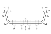
- FIG. 5A is a top view showing a state in which the hollow pipe blank 1S that has been bent is water-quenched
- FIG. 5B is a state in which the hollow pipe blank 1S that has been subjected to bending is swung during water quenching. It is the isometric view schematic diagram seen from diagonally upward direction. As shown in FIG. 5A, when the hollow pipe blank 1S is water-quenched, the hollow pipe blank 1S that has been subjected to bending may be thermally deformed.
- the straight torsion portion 1a of the hollow pipe base tube 1S is clamped by the clamps c1, c2, c3, and c4.
- the clamp c1 and the clamp c4 are arranged at a distance from the bent portion 1c of the torsion portion 1a in order to prevent the quenching of the bent portion 1c from being hindered. Consideration is made so that the portions clamped (clamped) by the clamps c1, c2, c3, and c4 have a small area in order to prevent insufficient cooling.
- the clamps c1, c2, c3, and c4 are arranged with a distance as much as possible almost symmetrically and at almost equal intervals. Thereby, a deformation
- the hollow pipe base tube 1S fixed to the quenching jig is quenched by being swung as shown by arrows ⁇ 1 and ⁇ 2 in the coolant water by the quenching jig J. Done. That is, restraint quenching is performed.
- the hollow pipe element 1S that has been subjected to bending is prevented from being thermally deformed by cooling.
- FIGS. 6A to 6C show that when water quenching is performed, the hollow pipe base tube 1S does not swing, the hollow pipe base tube 1S swing speed is 220 mm / sec, and the hollow pipe base tube 1S swing speed is 500 mm / sec. It is the figure which compared the Rockwell hardness (HRC) of.
- the horizontal axis represents t (plate thickness) / D (outer diameter), and the vertical axis represents Rockwell hardness (HRC).
- Rockwell hardness 40.0 indicates a lower limit of specification, a two-dot chain line indicates a maximum value of hardness, a broken line indicates a minimum value of hardness, and a solid line indicates an average value of hardness.
- the hollow pipe element 1S is effectively and efficiently cooled with water of the coolant by setting the hollow pipe element 1S to a swing speed of 350 mm / sec or more and about 650 mm / sec during the water quenching. It is possible to improve and homogenize the quenching hardness.
- fluctuate hollow pipe elementary pipe 1S is also possible by changing the kind of coolant, accelerating the circulation speed of coolant, or lowering the temperature of coolant.
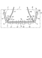
- FIG. 7 is a top view showing a state in which the inside of the bent portion 1c of the hollow pipe blank 1S that has been bent is locally quenched from the outer surface.
- the inner portions 1c1 and 1c2 of the bent portions 1c and 1c may not be completely quenched.
- t (plate thickness) / D (outer diameter) 0.18 to 0.275
- the plate thickness of the hollow pipe base tube 1S is increased, so that quenching may be insufficient. In this case, quenching by an outer jet is performed.
- the quenching by the outer surface jet is a jet of coolant on each outer surface 1e of the inner side 1c1, 1c2 of the bent portions 1c, 1c of the hollow pipe base tube 1S which is bent during water quenching.
- a jet of water is continuously injected and cooled rapidly.
- the coolant jet may be a liquid other than water, a gas jet, for example, a gas using a trade name “Colder” or the like.
- a gaseous jet flow is used, the metal hollow stabilizer 1 has a rust prevention effect. Moreover, there is an effect that the production line becomes simple.
- a nozzle n1 for injecting water into the inner side 1c1 of the bent portion 1c on one side is connected to the tip of the hose h1 via a small submersible pump p1.
- a nozzle n2 for injecting water into the inner side 1c2 of the other bent portion 1c is connected to the tip of the hose h2 via a small submersible pump p2.
- At least the nozzles n1 and n2 are integrally fixed to the quenching jig J, and the relative position with respect to the hollow pipe blank 1S is unchanged.
- the hose h1, h2 may be a bellows-structured flexible tube made of rubber, resin, metal such as stainless steel (SUS), and smoothly supplies coolant water such as flexibility and rust prevention for a long time. If it has a function which can be performed, it will not be specifically limited.
- the tip of the nozzle n1 on one side is directed toward the inner side 1c1 of the bending portion 1c on one side of the hollow pipe 1S that has been bent and bent. Then, by pumping the coolant water in the hose h1 with the small submersible pump p1, the jet water flow is applied from the nozzle n1 to the outer surface of the inside 1c1 of the bent portion 1c on one side, and rapidly cooled (quenched). At the same time, the tip of the nozzle n2 on the other side is directed toward the inner side 1c2 of the bent portion 1c on the other side of the hollow pipe base tube 1S.
- the jet water flow is applied from the nozzle n2 to the outer surface of the inner side 1c2 of the bent portion 1c on the other side, and is rapidly cooled (quenched).
- the flow rate of the outer surface jet to the insides 1c1 and 1c2 of the bent portion 1c of the hollow pipe base tube 1S is preferably a jet flow rate of 8.5 liters / min or more and a flow rate of 2000 mm / sec or more.
- the jet flow rate was less than 8.5 l / min and the flow rate was less than 2000 mm / sec, the cooling rate of the bent portion 1c of the hollow pipe base tube 1S was reduced. Thereby, hardening of each inner side 1c1, 1c2 of the bending parts 1c, 1c of the hollow pipe base tube 1S formed by bending can be made more complete.
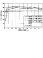
- FIG. 8 is a diagram showing the effect of the outer jet in terms of hardness.
- the horizontal axis represents the depth (distance) from the surface of the inside 1c1, 1c2 of the bent portion 1c of the hollow pipe base tube 1S, and the vertical axis represents Vickers hardness.
- the indenter load in the Vickers hardness test is 300 gf.
- Rockwell hardness HRC40 and 43 are shown for reference.
- Test tube A without an outer jet is indicated by a thick solid line
- test tube A with an outer jet is indicated by a thick broken line
- the outer jet of the test tube B is indicated by a thin solid line
- the outer jet of the test tube B is indicated by a thin broken line.
- the tempering step S30 is a step of tempering the quenched hollow pipe base tube 1S.
- Tempering is a process of heating and cooling performed to bring the metastable metal structure obtained by quenching into transformation or precipitation, bring it closer to the stable structure, and give the required properties and conditions (particularly to increase toughness). It is. Heating is performed at a temperature below the Ac1 transformation point by a heating furnace, energization heating, and high frequency induction heating. Cooling can be performed by any method such as water cooling.
- Table 1 is a table
- FIG. 9 shows that the test tube C molded at a temperature of about 900 ° C. or higher and about 1200 ° C. or lower is tempered at a tempering temperature of 350 ° C.
- FIG. 5 is an SN diagram comparing the durability after tempering at 400 ° C.
- the horizontal axis indicates the number of durability (number of repetitions), and the vertical axis indicates the stress amplitude (MPa) (fatigue strength).
- MPa stress amplitude
- the tempering life (the number of fatigue fractures) of the test tube C formed from the hollow pipe element 1S in the molding step S10 at about 900 ° C. or more and about 1200 ° C. or less to 350 ° C. is indicated by “ ⁇ ”, and the molding step S10
- the tempering life (number of fatigue fractures) of the test tube D formed from the hollow pipe element 1S at 350 ° C. to 350 ° C. is indicated by “ ⁇ ”, which is also about 900 ° C. or higher.
- the tempering life (number of fatigue fractures) of the test tube D molded at 1200 ° C. or lower to 400 ° C. is indicated by “ ⁇ ”. As shown in FIG.
- the test tubes C and D obtained by forming the hollow pipe element 1S at about 900 ° C. or more and about 1200 ° C. or less can obtain the same life as the conventional one at tempering temperatures of 350 ° C. and 400 ° C. It became clear.
- FIG. 10 is an SN diagram comparing the durability of tempering temperatures of 250 ° C. and 300 ° C. for steel type D formed at about 720 ° C. or less.
- the horizontal axis indicates the number of durability (number of repetitions), and the vertical axis indicates the stress amplitude (MPa) (fatigue strength).
- MPa stress amplitude
- FIG. 10 for reference, the 50% breakage probability (average) of the Weibull distribution of a conventional hollow pipe with only water quenching is indicated by a one-dot chain line, and the 10% breakage probability (average) is indicated by a broken line.
- the tempering life (number of fatigue fractures) of the test tube D to 250 ° C is indicated by “ ⁇ ”, and the tempering life of the test tube D to 300 ° C (the number of fatigue fractures) is indicated by “ ⁇ ”. Show
- the heating temperature for tempering is preferably about 200 ° C. to about 290 ° C., and most preferably about 230 ° C. to about 270 ° C.
- connection portion 1d and 1d connected to the stabilizer link 2 (see FIGS. 1A and 1B) by processing both ends of the hollow pipe base tube 1S which is bent and formed.
- the end of the hollow pipe base tube 1S that has been bent is plastically deformed by compression using a press to form a flat shape, and then a hole is formed with a punching die.
- the connecting portions 1d and 1d having the attachment holes 1d1 and 1d1 at the ends of the bent hollow pipe base tube 1S are formed.
- the form and formation method of connection part 1d, 1d are not restrict
- the painting step S60 is a step of painting the hollow pipe base tube 1S.
- first, surface cleaning and surface treatment are performed.
- Various pretreatments such as a removal treatment for removing fats and oils, foreign matters and the like and a ground treatment are performed on the surface of the hollow pipe base tube 1S.
- a coating such as zinc phosphate or iron phosphate can be formed.
- the hollow pipe base 1S is preheated.
- the coating processing efficiency can be improved.
- the adhesion of the coating film can be improved.
- a heating method an appropriate method such as heating with a heating furnace or infrared heating can be used.
- the residual heat after heat drying can be used for applying the paint. Therefore, when the heating and drying temperature in draining is sufficiently high, the coating may be performed without preheating after the pretreatment.
- the hollow pipe base tube 1S is coated with a paint.
- a powder paint is preferably used, and for example, a powder paint made of an epoxy resin can be suitably used.
- a coating method for example, a method of spraying a paint so that a coating film having a thickness of about 50 ⁇ m or more is formed on the surface of the hollow stabilizer 1 or a method of immersing in a paint can be used.
- the coating treatment electrodeposition coating, solvent coating, or the like may be performed.
- the hollow stabilizer 1 (see FIG. 1B) can be manufactured.
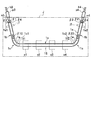
- quenching is performed by an inner jet of a coolant that locally quenches the hollow pipe element 1S from the inner surface 1f.
- FIG. 11 is a top view showing a state in which the hollow pipe base tube 1S formed by bending is locally quenched from the inner surface by the quenching method using the inner surface jet. Quenching with the internal jet is performed as follows. Nozzles n3 and n4 corresponding to the inner diameter of the hollow pipe base tube 1S are arranged at intervals between the tube ends 1s1 and 1s2 of the openings at both ends of the hollow pipe base tube 1S. The diameters of the nozzles n3 and n4 are appropriately determined according to the inner diameter of the hollow pipe base tube 1S.
- the flexible hoses h3 and h4 are connected to the nozzles n3 and n4 via small submersible pumps p3 and p4, respectively.
- the hose h3, h4 may be a bellows-structured flexible tube made of rubber, resin, metal, such as stainless steel (SUS), and smoothly supply coolant water for a long time, such as flexibility and rust prevention. If it has a function which can be performed, it will not be specifically limited.
- the nozzles n3 and n4, the small submersible pumps p3 and p4, etc. are fixed to a quenching jig J to which the hollow pipe base pipe 1S is clamped, and are swung integrally with the hollow pipe base pipe 1S. That is, the relative position between the hollow pipe base tube 1S and the nozzles n3 and n4 remains unchanged during the quenching cooling of the hollow pipe base tube 1S.
- the water in the hoses h3 and h4 is pumped up by the small submersible pumps p3 and p4, respectively, and jet water flows from the nozzles n3 and n4 into the pipe ends 1s1 and 1s2 at the openings at both ends of the hollow pipe base pipe 1S, respectively. (White arrows ⁇ 1, ⁇ 2 in FIG. 11).
- the jet water flow that has entered the hollow pipe element 1S from one pipe end 1s1 flows in the pipe (the white arrow ⁇ 10 in FIG. 11), and rapidly cools the inner surfaces 1f1, 1f2 of the bent portions 1c, 1c in order, It is discharged from the other tube end 1s2 (arrow ⁇ 3 in FIG. 11).
- the jet water flow that has entered the hollow pipe element 1S from the other pipe end 1s2 flows in the pipe (the white arrow ⁇ 20 in FIG. 11), and rapidly turns the inner surfaces 1f2, 1f1 of both bent portions 1c, 1c in order. It cools and is discharged
- nozzles n3 and n4 are arranged separately from the tube ends 1s1 and 1s2 of the hollow pipe base tube 1S, discharge of the jet water flow (arrows ⁇ 3 and ⁇ 4 in FIG. 11) is not hindered.
- the diameters of the nozzles n3 and n4 can be appropriately set so that the jet water flow from both directions can be smoothly performed.
- the flow rate of the inner surface jet into the hollow pipe base tube 1S is desirably a jet flow rate of 8.5 liter / min or more and a flow rate of 2000 mm / sec or more.
- the cooling rate of the bent portion 1c of the hollow pipe base tube 1S was reduced.
- FIG. 12 is a SN diagram showing the effect of water quenching and quenching by an internal jet in a fatigue test in comparison with the case of water quenching alone.
- the horizontal axis indicates the number of durability (number of repetitions), and the vertical axis indicates the stress amplitude (MPa) (fatigue strength).
- MPa stress amplitude
- FIG. 12 the 50% breakage probability (average) of the Weibull distribution of the conventional hollow pipe only with water quenching is indicated by a one-dot chain line, and the 10% breakage probability (average) is indicated by a broken line.
- the number of fatigue fractures of the conventional hollow pipe 1S hollow pipe only is indicated by “ ⁇ ”, and the number of fatigue fractures of the quenched hollow pipe blank 1S obtained by adding quenching by an internal jet water flow to the water quenching of this embodiment. Is indicated by “ ⁇ ”. From FIG. 12, it was confirmed that the number of times of durability increased with the inner surface jet ( ⁇ ) compared to the case without the inner surface jet ( ⁇ ), and the durability was improved by performing the inner surface jet.
- the coolant injection from the nozzles n3 and n4 may be performed alternately. Of course, even with a gas jet flow such as the trade name “Colder”, the heat treatment effect by rapid cooling of the hollow stabilizer 1 can be obtained. Moreover, the effect that the manufacturing line of the hollow stabilizer 1 becomes simple and the manufacturing line becomes clean is obtained.
- FIG. 13 is a top view showing a state in which the bent hollow pipe base tube 1S is quenched from the inner surface by the quenching method using the inner surface jet of another example.
- the quenching method using the second inner surface jet is performed as follows.
- a nozzle n5 is arranged at a suitable distance away from the tube end 1s1 of one opening of the hollow pipe base tube 1S.
- the diameter of the nozzle n5 is appropriately determined according to the inner diameter of the hollow pipe base tube 1S.
- a tubular injection guard g1 is provided that softens the flow rate of the jet water flow discharged from the tube end 1s2.
- a flexible hose h5 is connected to each nozzle n5 via a small submersible pump p5.
- the hose h5 is arbitrarily made of rubber, resin, metal or the like.
- the nozzle n5, the injection guard g1, etc. are fixed to a quenching jig J to which the hollow pipe base tube 1S is clamped, and are swung integrally with the hollow pipe base tube 1S.
- the relative positions of the hollow pipe shell 1S, the nozzle n5, and the injection guard g1 remain unchanged during cooling of the quenching of the hollow pipe shell 1S.
- Water in the hose h5 is pumped up by the small submersible pump p5, and a jet water flow is ejected from the nozzle n5 into the tube end 1s1 of the opening at one end of the hollow pipe base tube 1S (the white arrow ⁇ 5 in FIG. 13). ).
- the jet water flow that has entered the hollow pipe element 1S from the one pipe end 1s1 flows in the pipe (the white arrow ⁇ 50 in FIG. 13), and rapidly turns the inner surface 1f1 of the bent portion 1c and the inner surface 1f2 of the bent portion 1c in order. It cools and is discharged
- the above-described second inner surface jet improves the hardenability of the inner surface 1f1 of the bent portion 1c1 of the hollow pipe base tube 1S and the inner surface 1f2 of the bent portion 1c2.
- the jet water flow simultaneously flows from the pipe ends 1s1 and 1s2 of the openings at both ends of the hollow pipe base pipe 1S because deformation due to quenching is further suppressed.
- quenching is performed in which rocking is performed by immersing in coolant water or the like.
- the outer surface jet flow is quenched.
- the plate thickness t becomes thick and the bending portion 1c may be insufficiently quenched.
- the outer surface stress is equivalent to that of a solid stabilizer, and the inner surface stress is relatively low, so the inner surface hardness may be low. That is, quenching may be performed by swinging the coolant immersed in water.
- the hollow stabilizer 1 in which the hardness of the outer surface 1e of the inner side 1c1, 1c2 of the bent portion 1c is at least about 70% or more can be realized.
- the hardness of the outer surface 1e of the inner side 1c1 and 1c2 of the bent portion 1c was about 34 to about 40% compared to the hardness of the outer surface 1e of the arm portion 1b.
- it could be about 70% or more.
- the hardness ratio is about 70% or more.
- the hardness of the outer surface 1e of the inner side 1c1, 1c2 of the bent portion 1c may be about 80% or more, or about 90% or more compared to the hardness of the outer surface 1e of the arm portion 1b. it can.
- the hardness is assumed to be Rockwell hardness or Vickers hardness.
- the coolant is continuously sprayed toward the outer surface 1e of the inner side 1c1, 1c2 of the bent portion 1c. Sufficient quenching can be applied to areas that are likely to be sufficient. Further, the cooling rate of the entire hollow stabilizer 1 can be improved.
- the coolant is continuously injected into the inner surface 1f of the bent portion 1c of the hollow stabilizer 1 from the tube end 1s1 or the tube end 1s2 at the end opening, the hardness of the inner surfaces 1f1, 1f2 of the bent portion 1c is increased. be able to. Further, the cooling rate of the entire hollow stabilizer 1 can be improved.
- the quenching hardness can be improved and made uniform by setting the rocking speed to about 350 mm / sec or more and about 650 mm / sec or less when immersed in the coolant during quenching.
- the hollow stabilizer 1 can be molded by molding at about 900 ° C. or more and about 1200 ° C. or less, the degree of freedom in shape is higher than bending molding by a molding vendor at about 720 ° C. or less.
- a molding vendor at about 720 ° C. or less.
- the hollow stabilizer 1 can be molded by molding at about 900 ° C. or more and about 1200 ° C. or less, productivity can be improved more than double compared to bending by a molding vendor at about 720 ° C. or less.
- the hollow stabilizer 1 can be molded by molding at about 900 ° C. or more and about 1200 ° C. or less, a solid stabilizer production line can be used.
- quenching with a medium having a heat transfer coefficient equal to or higher than that of water can be employed.
- mineral oil for oil quenching is collected by a waste disposal company, which increases disposal costs.
- the water used for the water quenching of this embodiment can be discharged except for the scale. Therefore, the production cost of the hollow stabilizer 1 can be reduced. Further, the hollow stabilizer 1 can be efficiently produced.
- the hardness of the outer surface 1e of the inner side 1c1, 1c2 of the bent portion 1c can be at least about 70% or more as compared with the hardness of the outer surface 1e of the arm portion 1b of the thick hollow stabilizer 1.
- the hollow stabilizer 1 with improved durability and strength can be realized.
- Embodiments >> 1.
- the cooling by the outer surface jet or the inner surface jet of the coolant to the bending portion 1c of the hollow stabilizer 1 described in the above embodiment may be performed independently.
- the outer surface jet or the inner surface jet to the bent portion 1c of the hollow stabilizer 1 may be performed without performing the inner surface jet or the outer surface jet, respectively.
- quenching is performed at a lower critical cooling rate or higher than, for example, cold air, a gas such as a trade name “Colder”, and the like other than water
- the cooling of the liquid may be performed by spraying on the outer surface 1e of the inner side 1c1, 1c2 of the bent portion 1c of the hollow pipe base tube 1S that has been bent or by injecting the inner surface 1f.
- each configuration may be selected, or each configuration may be appropriately selected and combined.
Landscapes
- Engineering & Computer Science (AREA)
- Chemical & Material Sciences (AREA)
- Mechanical Engineering (AREA)
- Physics & Mathematics (AREA)
- Thermal Sciences (AREA)
- Crystallography & Structural Chemistry (AREA)
- Materials Engineering (AREA)
- Metallurgy (AREA)
- Organic Chemistry (AREA)
- Heat Treatment Of Articles (AREA)
- Vehicle Body Suspensions (AREA)
Abstract
Description
熱処理としては、焼入れ処理と焼戻し処理とが行われており、焼入れの方法は、油焼入れが主流である。そして、熱処理された素管は、通常、ショットピーニングによる表面加工処理や、塗装処理等の仕上処理を経て製品化されている。
例えば、特許文献1には、板厚tと外径Dの%比がt/D≧20%である中空スタビライザー用電縫溶接鋼管が、電縫溶接後に縮径圧延されてなる電縫溶接鋼管を採用することによって実現することが記載されている。
そこで、強度が高いながら軽量である中空スタビライザが求められるというニーズがある。
また、中空スタビライザの曲げ部は、焼入れに際して、通電加熱の場合に凹状のため電流密度が高く局所的な高温化を生じる場合がある。また、冷却に際しても曲げ部は凹状のために冷却速度が低く成り易い。そのため、曲げ部は、焼入れが不充分となり、硬度が低下するおそれがある。
一方、前記したように、中実構造の中実スタビライザは断面係数が高く、強度が高いものの、重量が嵩むという欠点がある。
中空スタビライザ1は、車幅方向に延びるトーション部1aと、車両の前後方向に延びる左右一対のアーム部1b,1bとを備えている。
なお、曲げ部1cは2か所以上有する構成としてもよい。
アーム部1b,1bの先端の各連結部1d、1dは、スタビライザリンク2,2を介して、不図示の車体に固定される左右一対の懸架装置3,3にそれぞれ連結されている。各懸架装置3の車軸部3aには、不図示の車輪が取り付けられる。懸架装置3は、圧縮ばね、オイルダンパを有し、車輪からの衝撃、振動等を内部摩擦、粘性抵抗により減衰して車体に和らげて伝える働きをする。
この構成により、左右の車輪の上下移動により左右の懸架装置3,3にストローク差が生じると、各懸架装置3,3から各アーム部1b,1bに変位による荷重が伝達され、トーション部1aがねじり変形する。そして、トーション部1aには、該ねじり変形を復元しようとする弾性力が生じる。中空スタビライザ1は、このねじり変形に抗する弾性力によって、車体の左右の傾きを抑えてロール剛性を高め、車両の走行を安定化させる。
中空スタビライザ1に用いられる中空パイプは、電縫管、SR(Stretch Reduce)管(熱間圧延電縫鋼管)、電縫引抜鋼管等が使用される。図2Aは、電縫管を示す横断面図であり、図2Bは、SR管を示す横断面図である。
また、外径約12mm~約44mm、板厚tが約2mm~約10mmの中空スタビライザ1には、SR管が使用される。t/D=0.12~0.31程度の中空スタビライザ1である。
中空スタビライザ1は、後記する冷却剤への浸漬や冷却剤の噴射、噴入を含む冷却を伴う焼入れを行うことにより、主相がマルテンサイトである金属組織で形成されている。
このように、残留応力は金属材料の寿命と密接な関係があり、特に繰返し負荷によってき裂が徐々に進展する金属疲労においては、影響が顕著となる。
中空スタビライザ1の素管の中空パイプの焼入れ時には、熱応力による圧縮残留応力と変態応力による引張残留応力とが発生する。これらの兼ね合いから、表面残留応力が所定の分布を示すことになる。中空パイプの表面近傍は、水焼入れによって発生する熱応力は圧縮残留応力が優位である。
そこで、本中空スタビライザ1では、通常の水焼入れに加えて、後記するジェット水流による局所的な焼入れを補完的に行っている。
中空スタビライザ1は、主相がマルテンサイトである金属組織を有している。より具体的には、中空スタビライザ1の金属組織の少なくとも90%以上にマルテンサイト組織を有する。
次に、中実スタビライザと本実施形態の中空スタビライザ1とをt(板厚)/D(外径)で重量比較するとともに、中空スタビライザ1の外面1fと内面1eとに発生する応力を定性的に相対比較した結果を説明する。
図3においては、中実スタビライザの場合を100%として、中空スタビライザでどのように重量、外面応力、内面応力が変化するかを表わしている。そのため、中実スタビライザの重量、外面応力が100%であり、中実スタビライザは、内面がなく内面応力が発生しないので、内面応力は0%である。
中実スタビライザからt/Dが低下する中空スタビライザとなると断面積が減少することから、外面応力、内面応力は増加する傾向となる。
なお、t/D=約0.275の中空スタビライザ1とすると重量が約20%低下できる。
t/D=約0.18以下では、内面からの疲労破壊が発生する。t/D=約0.18以下では、内面応力および外面応力ともに急激に上昇する。
そこで、t/D=約0.18以下では、内面の硬度の向上がより重要である。
また、中空スタビライザ1は、t/D=約0.18~0.275など板厚tが厚くなるので、前記したように、曲げ部1cの内側の焼入れが不充分となるおそれがある。
次に、本実施形態に係る中空スタビライザの製造方法の一例について説明する。
素材の中空パイプ材の長さ及び径は、所望の製品形状に応じて適宜の寸法とすることが可能である。
上述の熱間圧延鋼材を用いて、前記の電縫管、SR管等が製管される。そして、所定長さの中空スタビライザ1を製造する電縫管、SR管等の中空パイプ素管1Sが用意される。
加熱方法としては、加熱炉による加熱、通電加熱、高周波誘導加熱等の適宜の方法を用いることができる。通電加熱は、急速加熱によって脱炭や脱ホウ素を抑制しつつ中空パイプ素管1Sを加熱処理することができる。そのため、通電加熱を用いることが好ましい。
なお、約720℃以下での曲げ成形としてもよい。
約720℃以下での曲げ加工を施した場合には、約900℃以上約1200℃以下での成形と異なり、金属が柔らかくなっていない状態での曲げ加工となるため、大きな力をかける必要がある。
これに対して、加熱温度が金属の再結晶温度以上での曲げ加工の場合、金属が柔らかく、曲げと曲げとの間隔はベンダによる曲げの半分程度で済み、約900℃以上約1200℃以下での型成形は加工性がよい。
型成形によって、中空パイプ素管1Sに曲げ加工を施すことによって、中空パイプ素管1Sにトーション部1a及びアーム部1b、曲げ部1cを形成し、中空パイプ素管1Sの形状を所望の中空スタビライザ1の形状近くに賦形される。
本実施形態では、冷却剤として水を用いており、不図示の焼入れ槽内の水の温度上昇を抑えるため、循環させている。
図5Aに示すように、中空パイプ素管1Sは水焼入れする際に、曲げ加工が施された中空パイプ素管1Sが熱変形するおそれがある。
クランプc1、c2、c3、c4によりクランプ(把持)される箇所は、冷却が不充分となるのを防ぐため小さい面積になるように配慮する。
これにより、水焼入れ中、中空パイプ素管1Sは焼入れ冶具Jに一体的固定される。
中空パイプ素管1Sをクランプして拘束焼入れすることにより、曲げ加工が施された中空パイプ素管1Sは冷却による熱変形することが抑えられる。
そこで、焼入れ中、中空パイプ素管1Sを揺動速度220mm/secで揺動させたところ、図6Bに示すように、規格下限より低い硬さのt/Dがなくなり、硬さの下限が上昇した。
なお、冷却剤の種類を変えたり、冷却剤の循環速度を速めたり、冷却剤の温度を低下させるなどして、中空パイプ素管1Sの揺動を行わない構成も可能である。
図7は、曲げ成形された中空パイプ素管1Sの曲げ部1cの内側を外面から局所的に焼入れを行っている状態を示す上面図である。
ところで、前記したように、中空パイプ素管1Sが厚肉の場合、曲げ部1c,1c(図1A、図1B参照)の内側1c1、1c2は、焼入れが完全に入らないおそれがある。
例えば、t(板厚)/D(外径)=0.18~0.275の場合、中空パイプ素管1Sの板厚が厚くなるので、焼き入れが不充分になるおそれがある。この場合、外面ジェットによる焼入れが行われる。
ジェット流量8.5リットル/min未満、流速2000mm/sec未満の場合、中空パイプ素管1Sの曲げ部1cの冷却速度が低下する結果となった。
これにより、曲げ成形された中空パイプ素管1Sの曲げ部1c、1cの各内側1c1、1c2の焼入れをより完全なものにすることができる。
図8は、外面ジェットによる効果を硬度で示す図である。横軸に中空パイプ素管1Sの曲げ部1cの内側1c1、1c2の表面からの深さ(距離)をとり、縦軸にビッカース硬さをとっている。なお、ビッカース硬さ試験の圧子の荷重は300gfである。図8では、参考にロックウェル硬さHRC40、43を示す。
以上より、中空パイプ素管1Sの曲げ部1cの内側1c1、1c2に冷却剤による外面ジェットを行うことで、焼入れ性が向上することが確認できた。
上述の冷却剤による外面ジェットは、中空パイプ素管1Sを冷却剤に浸漬することなく行ってもよい。

図9により、成形工程S10において、中空パイプ素管1Sを約900℃以上約1200℃以下で成形した供試管C、Dは、350℃、400℃の焼戻し温度で従来と同様な寿命が得られることが明らかになった。
これらの検討より、成形を約720℃以下で行う中空スタビライザ1の場合、焼戻しの加熱温度は約200℃~約290℃が望ましく、約230℃~約270℃が最も望ましいことが判明した。
管端加工工程S40では、曲げ成形された中空パイプ素管1Sの末端をプレスによる圧縮加工で塑性変形させて扁平状に形成した後、穴開け型で孔開けする。これにより、曲げ成形された中空パイプ素管1Sの末端に取り付け孔1d1、1d1をそれぞれ有する連結部1d、1dが形成される。なお、連結部1d、1dの形態や形成方法は、特に制限されない。
中空パイプ素管1Sに塗装処理を行うため、まず表面洗浄や表面処理を行う。中空パイプ素管1Sの表面に、油脂分や異物等を除去する除去処理や下地処理等の各種の前処理を施す。下地処理としては、例えば、リン酸亜鉛、リン酸鉄等の被膜を形成することができる。
塗装処理として、電着塗装、溶剤塗装等を実施してもよい。
<内面ジェットによる焼入れ>
中空パイプ素管1Sの曲げ部1cの内側1c1、1c2の焼入れ性を上げたい場合、中空パイプ素管1Sを内面1fから局所的に焼入れを行う冷却剤の内面ジェットによる焼入れが行われる。
図11は、内面ジェットによる焼入れ方法で、曲げ成形された中空パイプ素管1Sを内面から局所的に焼入れを行っている状態を示す上面図である。
内面ジェットによる焼入れは、次のようにして行われる。
中空パイプ素管1Sの両端部の開口の管端1s1、1s2に間隔をおいて、それぞれ中空パイプ素管1Sの内径に対応したノズルn3、n4が配置される。ノズルn3、n4の径は中空パイプ素管1Sの内径に対応して、適宜に定められる。
なお、中空パイプ素管1S内への内面ジェットの流量は、検討結果、ジェット流量8.5リットル/min以上、流速2000mm/sec以上が望ましい。
ジェット流量8.5リットル/min未満、流速2000mm/sec未満の場合、中空パイプ素管1Sの曲げ部1cの冷却速度が低下する結果となった。
図12は、水焼入れおよび内面ジェットによる焼入れの効果を、水焼入れのみの場合との比較を疲労試験で示すS-N線図である。横軸に耐久回数(繰返し数)を示し、縦軸に応力振幅(MPa)(疲労強度)を示す。図12では、従来の水焼入れのみの中空パイプ素管のワイブル分布の50%折損確率(平均)を一点鎖線で示し、10%折損確率(平均)を破線で示す。
図12より、内面ジェット有り(△)の場合が内面ジェット無し(▲)の場合より耐久回数が上昇し、内面ジェットを行うことで耐久性が向上することが確認された。
なお、ノズルn3、n4からの冷却剤の噴入は互い違いに行ってもよい。
もちろん、商品名「コルダー」等の気体ジェット流であっても、中空スタビライザ1の急冷による熱処理効果が得られる。また、中空スタビライザ1の製造ラインが簡便になるとともに製造ラインがクリーンになるという効果が得られる。
図13は、他例の内面ジェットによる焼入れ方法で、曲げ成形された中空パイプ素管1Sを内面から焼入れを行っている状態を示す上面図である。
第2の内面ジェットによる焼入れ方法は、次のようにして行われる。
中空パイプ素管1Sの一方の開口の管端1s1に対向して適切な距離離膈して、ノズルn5が配置される。ノズルn5の径は中空パイプ素管1Sの内径に対応して、適宜に定められる。
ノズルn5にはそれぞれ小型水中ポンプp5を介して、可撓性のホースh5が接続される。ホースh5は、ゴム製、樹脂製、金属製等任意である。
一方の管端1s1から中空パイプ素管1S内に入ったジェット水流は、管内を流れ(図13の白抜き矢印β50)、曲げ部1cの内面1f1と曲げ部1cの内面1f2とを順に急速に冷却し、他方の管端1s2から排出される(図13の矢印β6)。
なお、中空パイプ素管1Sの両端部の開口の管端1s1、1s2から、同時にジェット水流を流す場合の方が焼入れによる変形がより抑えられ、より好ましい。
図3により、t/D=約0.18未満では、外面応力および内面応力が急激に増加することから、ショットピーニングや、表面から炭素を拡散させて表面に高炭素の合金の層を作り、より内面の硬さを高くする浸炭が行われる。
そこで、t/D=約0.18~0.275などの領域では、前記した冷却剤を中空スタビライザ1の曲げ部1cの内側1c1、1c2に対して噴射する冷却を伴う焼入れで中空スタビライザ1の曲げ部1cの内側1c1、1c2の硬度を高め、焼入れ不足を改善する。
t/D=約0.275以上では、外面応力が中実スタビライザと同等であり、内面応力が比較的低いので内面硬さは低くてもよい。つまり、前記の冷却剤の水などに浸漬した揺動を行う焼入れを行えばよい。
なお、ジェット流なしの場合、アーム部1bの外面1eの硬度に比べて、曲げ部1cの内側1c1、1c2の外面1eの硬度が約34~約40%であったが、ジェット流を用いることで、約70%以上とすることができた。結果として、硬さ比が約70%以上であれば実用レベルにあると言える。
また、ジェット水流による焼入れを工夫することでアーム部1bの外面1eの硬度に比べて、曲げ部1cの内側1c1、1c2の外面1eの硬度が約80%以上や約90%以上とすることができる。硬度は、ロックウェル硬度またはビッカース硬度によるものとする。
1.中空スタビライザ1の曲げ部1cに冷却剤に浸漬する焼入れに加えて、曲げ部1cの内側1c1、1c2の外面1eに向かって冷却剤を連続的に噴射するので、冷却剤に浸漬する焼入れでは不充分となり易い箇所に充分な焼入れを施すことができる。また、中空スタビライザ1全体の冷却速度向上を図ることができる。
そのため、中空スタビライザ1の生産コストを、低減できる。また、中空スタビライザ1の効率的な生産が可能になる。
1.前記実施形態で説明した中空スタビライザ1の曲げ部1cへの冷却剤の外面ジェットまたは内面ジェットによる冷却は単独で独立して行ってもよい。
例えば、中空スタビライザ1の曲げ部1cへの外面ジェットまたは内面ジェットは、それぞれ内面ジェットまたは外面ジェットを行うことなく行ってもよい。また、冷却剤に浸漬する焼入れを行うことなく、外面ジェットまたは内面ジェットを行ってもよい。
1a トーション部
1b アーム部
1c 曲げ部
1e 外面
1f1、1f2 内面
1s1、1s2 開口
1S 中空パイプ素管(素管)
Claims (13)
- 車両に備えられ、車幅方向に延びるトーション部と、車両の前後方向に延びるアーム部と、前記トーション部と前記アーム部とを接続する曲げ部とを備える管状の中空スタビライザであって、
前記アーム部外面の硬度に対して、前記曲げ部の曲げ内側の外面の硬度が70%以上である
ことを特徴とする中空スタビライザ。 - 車両に備えられ、車幅方向に延びるトーション部と、車両の前後方向に延びるアーム部と、前記トーション部と前記アーム部とを接続する曲げ部とを備える管状の中空スタビライザであって、
前記曲げ部は、局所的にまたは内面側から硬度が高められる処理が行われている
ことを特徴とする中空スタビライザ。 - 板厚をtとし、外径をDとした場合、t/D=0.18以上0.5未満であり、
前記曲げ部の曲げ内側の外面に対して冷却剤が噴射される冷却を伴う焼入れが施されている
ことを特徴とする請求項1または請求項2に記載の中空スタビライザ。 - 板厚をtとし、外径をDとした場合、t/D=0.25~0.275未満であり、
前記中空スタビライザの内部に冷却剤が噴入される冷却を伴う焼入れが施されている
ことを特徴とする請求項1または請求項2に記載の中空スタビライザ。 - 板厚をtとし、外径をDとした場合、t/D=0.1~0.18であり、
前記曲げ部の曲げ内側の外面または内面に、少なくともショットピーニングまたは浸炭の何れかが施されている
ことを特徴とする請求項1または請求項2に記載の中空スタビライザ。 - 車両に備えられ、車幅方向に延びるトーション部と、車両の前後方向に延びるアーム部と、前記トーション部と前記アーム部とを接続する曲げ部とを備える管状の中空スタビライザであって、
前記曲げ部の曲げ内側の外面に対して冷却剤が噴射される焼入れが施されている
ことを特徴とする中空スタビライザ。 - 左右の前記曲げ部の曲げ内側の両外面に対して一緒に前記冷却剤が噴射されている
ことを特徴とする請求項6に記載の中空スタビライザ。 - 車両に備えられ、車幅方向に延びるトーション部と、車両の前後方向に延びるアーム部と、前記トーション部と前記アーム部とを接続する曲げ部とを備える管状の中空スタビライザであって、
前記中空スタビライザの内部に冷却剤が噴入される焼入れが施されている
ことを特徴とする中空スタビライザ。 - 前記中空スタビライザの両端部から冷却剤が噴入される焼入れが施されている
ことを特徴とする請求項4または請求項8に記載の中空スタビライザ。 - 前記冷却剤は、流量8.5リットル/min以上、流速2000mm/sec以上で噴射または噴入される
ことを特徴とする請求項1または請求項2または請求項6または請求項8に記載の中空スタビライザ。 - 冷却剤に浸漬して冷却する焼入れが施され、
揺動速度350mm/sec以上650mm/secで揺動される
ことを特徴とする請求項1または請求項2または請求項6または請求項8に記載の中空スタビライザ。 - 900℃から1200℃で曲げ成形が行われている
ことを特徴とする請求項1または請求項2または請求項6または請求項8に記載の中空スタビライザ。 - 720℃以下で曲げ成形が行われ、
230℃~270℃に加熱して焼戻しが行われている
ことを特徴とする請求項1または請求項2または請求項6または請求項8に記載の中空スタビライザ。
Priority Applications (8)
| Application Number | Priority Date | Filing Date | Title |
|---|---|---|---|
| CA2980524A CA2980524C (en) | 2015-03-24 | 2016-03-16 | Hollow stabilizer |
| EP16768571.8A EP3279016B1 (en) | 2015-03-24 | 2016-03-16 | Hollow stabilizer |
| US15/560,892 US10442269B2 (en) | 2015-03-24 | 2016-03-16 | Hollow stabilizer |
| KR1020177026389A KR101984288B1 (ko) | 2015-03-24 | 2016-03-16 | 중공 스태빌라이저 |
| MX2017012087A MX2017012087A (es) | 2015-03-24 | 2016-03-16 | Estabiizador hueco. |
| CN201680017784.6A CN107428220A (zh) | 2015-03-24 | 2016-03-16 | 中空稳定器 |
| ES16768571T ES3041918T3 (en) | 2015-03-24 | 2016-03-16 | Hollow stabilizer |
| CN201911166838.7A CN110978934B (zh) | 2015-03-24 | 2016-03-16 | 中空稳定器 |
Applications Claiming Priority (2)
| Application Number | Priority Date | Filing Date | Title |
|---|---|---|---|
| JP2015061552A JP6494357B2 (ja) | 2015-03-24 | 2015-03-24 | 中空スタビライザの製造方法 |
| JP2015-061552 | 2015-03-24 |
Publications (1)
| Publication Number | Publication Date |
|---|---|
| WO2016152668A1 true WO2016152668A1 (ja) | 2016-09-29 |
Family
ID=56978451
Family Applications (1)
| Application Number | Title | Priority Date | Filing Date |
|---|---|---|---|
| PCT/JP2016/058278 Ceased WO2016152668A1 (ja) | 2015-03-24 | 2016-03-16 | 中空スタビライザ |
Country Status (9)
| Country | Link |
|---|---|
| US (1) | US10442269B2 (ja) |
| EP (1) | EP3279016B1 (ja) |
| JP (1) | JP6494357B2 (ja) |
| KR (1) | KR101984288B1 (ja) |
| CN (2) | CN110978934B (ja) |
| CA (1) | CA2980524C (ja) |
| ES (1) | ES3041918T3 (ja) |
| MX (1) | MX2017012087A (ja) |
| WO (1) | WO2016152668A1 (ja) |
Cited By (1)
| Publication number | Priority date | Publication date | Assignee | Title |
|---|---|---|---|---|
| WO2018186102A1 (ja) * | 2017-04-05 | 2018-10-11 | 新日鐵住金株式会社 | 車両足回り部品素材の製造方法および製造装置、車両足回り部品素材製造用焼入れ用鋼材ならびに車両足回り部品素材 |
Families Citing this family (5)
| Publication number | Priority date | Publication date | Assignee | Title |
|---|---|---|---|---|
| EP3357724B1 (en) * | 2015-10-02 | 2020-08-26 | NHK Spring Co., Ltd. | Stabilizer for vehicle |
| EP3653414B1 (en) * | 2017-07-14 | 2023-06-28 | NHK Spring Co., Ltd. | Vehicle stabilizer, and shot peening jig with stabilizers |
| RU200772U1 (ru) * | 2020-06-25 | 2020-11-11 | Публичное акционерное общество "КАМАЗ" | Штанга стабилизатора грузового автомобиля |
| JP2023146950A (ja) * | 2022-03-29 | 2023-10-12 | 日本発條株式会社 | スタビライザの製造方法 |
| US20250196553A1 (en) * | 2022-06-01 | 2025-06-19 | Nippon Steel Corporation | Torsion beam |
Citations (10)
| Publication number | Priority date | Publication date | Assignee | Title |
|---|---|---|---|---|
| JPS56127731A (en) * | 1980-03-13 | 1981-10-06 | Kawasaki Steel Corp | Quenching method of steel pipe |
| JPS58141332A (ja) * | 1982-02-17 | 1983-08-22 | Kawasaki Steel Corp | 管状体の浸漬冷却における形状変化防止方法 |
| JPS63186831A (ja) * | 1987-01-28 | 1988-08-02 | Nippon Steel Corp | 鋼管の内面焼入方法 |
| JPH0931541A (ja) * | 1995-07-17 | 1997-02-04 | Toshiba Corp | 高Crフェライト鋼管の製造方法 |
| JP2001152315A (ja) * | 1999-11-22 | 2001-06-05 | Nhk Spring Co Ltd | 中空スタビライザと、その製造方法 |
| JP2002331326A (ja) * | 2001-03-08 | 2002-11-19 | Nhk Spring Co Ltd | 中空スタビライザおよびその製造方法 |
| JP2010228555A (ja) * | 2009-03-26 | 2010-10-14 | Chuo Spring Co Ltd | 車両用スタビライザとその製造方法 |
| JP2012052197A (ja) * | 2010-09-02 | 2012-03-15 | Sumitomo Metal Ind Ltd | 鋼管の焼入れ方法およびそれを用いた鋼管の製造方法 |
| JP2013086798A (ja) * | 2011-10-21 | 2013-05-13 | Luhn & Pulvermacher-Dittmann & Neuhaus Gmbh | 繊維強化合成樹脂複合構造におけるスタビライザ及びその製造方法 |
| WO2014054287A1 (ja) * | 2012-10-04 | 2014-04-10 | Jfeスチール株式会社 | 厚肉鋼管の製造方法 |
Family Cites Families (20)
| Publication number | Priority date | Publication date | Assignee | Title |
|---|---|---|---|---|
| JPS5847366B2 (ja) * | 1979-09-07 | 1983-10-21 | 日本発条株式会社 | 車輛用スタビライザ |
| JPS57134520A (en) * | 1981-02-13 | 1982-08-19 | Nhk Spring Co Ltd | Heat treatment of hollow stabilizer |
| JPS5953631A (ja) * | 1982-09-21 | 1984-03-28 | Nippon Steel Corp | パイプ冷却装置 |
| US4781054A (en) * | 1986-12-19 | 1988-11-01 | Rockwell International Suspension Systems Company | Apparatus for bending and forming heated tubular workpieces |
| JPH01111848A (ja) * | 1987-10-26 | 1989-04-28 | Nisshin Steel Co Ltd | スタビライザーに用いられるパイプ素管 |
| JP2000024737A (ja) * | 1998-07-14 | 2000-01-25 | Mitsubishi Motors Corp | スタビライザバーの製造方法 |
| JP2004009126A (ja) | 2002-06-11 | 2004-01-15 | Nippon Steel Corp | 中空スタビライザー用電縫溶接鋼管 |
| JP2006137997A (ja) * | 2004-11-12 | 2006-06-01 | Toyota Motor Corp | 中空部材の焼き入れ装置及び焼き入れ方法 |
| US7744708B2 (en) | 2006-03-14 | 2010-06-29 | Tenaris Connections Limited | Methods of producing high-strength metal tubular bars possessing improved cold formability |
| JP4976242B2 (ja) * | 2007-09-05 | 2012-07-18 | 山陽特殊製鋼株式会社 | 長尺鋼材の焼入れ方法 |
| CN201077855Y (zh) * | 2007-09-06 | 2008-06-25 | 上海中国弹簧制造有限公司 | 空心稳定杆的淬火夹具 |
| JP5511451B2 (ja) * | 2010-03-16 | 2014-06-04 | 中央発條株式会社 | 自動車用スタビライザの製造方法 |
| CN102189910B (zh) * | 2010-03-19 | 2013-02-27 | 上海中国弹簧制造有限公司 | 汽车空心稳定杆的制造工艺 |
| JP5757475B2 (ja) * | 2010-12-08 | 2015-07-29 | Dowaサーモテック株式会社 | 焼入れ方法及び焼入れ装置 |
| DE102010054363B3 (de) * | 2010-12-13 | 2011-12-29 | Benteler Automobiltechnik Gmbh | Vorrichtung zur Wärmebehandlung von Langmaterial sowie Verfahren zum Wärmebehandeln eines Langmaterials |
| EP2857537B1 (en) | 2012-05-25 | 2018-07-25 | Nippon Steel & Sumitomo Metal Corporation | Hollow stabilizer, and steel pipe for hollow stabilizers and method for production thereof |
| JP5513555B2 (ja) * | 2012-06-15 | 2014-06-04 | 日本発條株式会社 | スタビライザの製造方法および加熱装置 |
| JP6077790B2 (ja) * | 2012-08-28 | 2017-02-08 | 日本発條株式会社 | スタビライザの製造方法および加熱装置 |
| JP5812293B2 (ja) * | 2012-10-04 | 2015-11-11 | 株式会社黒木工業所 | ベンド鋼管の製造方法 |
| KR20140048429A (ko) * | 2012-10-15 | 2014-04-24 | 현대자동차주식회사 | 상용차용 중공 스테빌라이저 바의 제조방법 |
-
2015
- 2015-03-24 JP JP2015061552A patent/JP6494357B2/ja active Active
-
2016
- 2016-03-16 CN CN201911166838.7A patent/CN110978934B/zh active Active
- 2016-03-16 CA CA2980524A patent/CA2980524C/en active Active
- 2016-03-16 CN CN201680017784.6A patent/CN107428220A/zh active Pending
- 2016-03-16 MX MX2017012087A patent/MX2017012087A/es unknown
- 2016-03-16 EP EP16768571.8A patent/EP3279016B1/en active Active
- 2016-03-16 ES ES16768571T patent/ES3041918T3/es active Active
- 2016-03-16 WO PCT/JP2016/058278 patent/WO2016152668A1/ja not_active Ceased
- 2016-03-16 KR KR1020177026389A patent/KR101984288B1/ko active Active
- 2016-03-16 US US15/560,892 patent/US10442269B2/en active Active
Patent Citations (10)
| Publication number | Priority date | Publication date | Assignee | Title |
|---|---|---|---|---|
| JPS56127731A (en) * | 1980-03-13 | 1981-10-06 | Kawasaki Steel Corp | Quenching method of steel pipe |
| JPS58141332A (ja) * | 1982-02-17 | 1983-08-22 | Kawasaki Steel Corp | 管状体の浸漬冷却における形状変化防止方法 |
| JPS63186831A (ja) * | 1987-01-28 | 1988-08-02 | Nippon Steel Corp | 鋼管の内面焼入方法 |
| JPH0931541A (ja) * | 1995-07-17 | 1997-02-04 | Toshiba Corp | 高Crフェライト鋼管の製造方法 |
| JP2001152315A (ja) * | 1999-11-22 | 2001-06-05 | Nhk Spring Co Ltd | 中空スタビライザと、その製造方法 |
| JP2002331326A (ja) * | 2001-03-08 | 2002-11-19 | Nhk Spring Co Ltd | 中空スタビライザおよびその製造方法 |
| JP2010228555A (ja) * | 2009-03-26 | 2010-10-14 | Chuo Spring Co Ltd | 車両用スタビライザとその製造方法 |
| JP2012052197A (ja) * | 2010-09-02 | 2012-03-15 | Sumitomo Metal Ind Ltd | 鋼管の焼入れ方法およびそれを用いた鋼管の製造方法 |
| JP2013086798A (ja) * | 2011-10-21 | 2013-05-13 | Luhn & Pulvermacher-Dittmann & Neuhaus Gmbh | 繊維強化合成樹脂複合構造におけるスタビライザ及びその製造方法 |
| WO2014054287A1 (ja) * | 2012-10-04 | 2014-04-10 | Jfeスチール株式会社 | 厚肉鋼管の製造方法 |
Non-Patent Citations (1)
| Title |
|---|
| See also references of EP3279016A4 * |
Cited By (2)
| Publication number | Priority date | Publication date | Assignee | Title |
|---|---|---|---|---|
| WO2018186102A1 (ja) * | 2017-04-05 | 2018-10-11 | 新日鐵住金株式会社 | 車両足回り部品素材の製造方法および製造装置、車両足回り部品素材製造用焼入れ用鋼材ならびに車両足回り部品素材 |
| JP6428981B1 (ja) * | 2017-04-05 | 2018-11-28 | 新日鐵住金株式会社 | 車両足回り部品素材の製造方法および製造装置、車両足回り部品素材製造用焼入れ用鋼材ならびに車両足回り部品素材 |
Also Published As
| Publication number | Publication date |
|---|---|
| CA2980524A1 (en) | 2016-09-29 |
| EP3279016A4 (en) | 2018-10-31 |
| ES3041918T3 (en) | 2025-11-17 |
| MX2017012087A (es) | 2018-07-06 |
| JP2016179765A (ja) | 2016-10-13 |
| CN110978934A (zh) | 2020-04-10 |
| US20180117983A1 (en) | 2018-05-03 |
| KR20170118205A (ko) | 2017-10-24 |
| EP3279016B1 (en) | 2025-08-27 |
| EP3279016A1 (en) | 2018-02-07 |
| CA2980524C (en) | 2021-03-23 |
| CN107428220A (zh) | 2017-12-01 |
| CN110978934B (zh) | 2023-05-02 |
| JP6494357B2 (ja) | 2019-04-03 |
| KR101984288B1 (ko) | 2019-05-30 |
| US10442269B2 (en) | 2019-10-15 |
Similar Documents
| Publication | Publication Date | Title |
|---|---|---|
| CN107249909B (zh) | 中空稳定器的制造方法 | |
| JP6494357B2 (ja) | 中空スタビライザの製造方法 | |
| US6682610B1 (en) | Manufacturing method for hollow stabilizer | |
| US7010950B2 (en) | Suspension component having localized material strengthening | |
| KR101923126B1 (ko) | 스태빌라이저 | |
| JP6110840B2 (ja) | スタビライザの製造方法 | |
| KR20140048429A (ko) | 상용차용 중공 스테빌라이저 바의 제조방법 | |
| WO2016158408A1 (ja) | 懸架装置用ばねの製造方法及び懸架装置用ばね |
Legal Events
| Date | Code | Title | Description |
|---|---|---|---|
| 121 | Ep: the epo has been informed by wipo that ep was designated in this application |
Ref document number: 16768571 Country of ref document: EP Kind code of ref document: A1 |
|
| ENP | Entry into the national phase |
Ref document number: 20177026389 Country of ref document: KR Kind code of ref document: A |
|
| ENP | Entry into the national phase |
Ref document number: 2980524 Country of ref document: CA |
|
| WWE | Wipo information: entry into national phase |
Ref document number: 15560892 Country of ref document: US |
|
| WWE | Wipo information: entry into national phase |
Ref document number: MX/A/2017/012087 Country of ref document: MX |
|
| NENP | Non-entry into the national phase |
Ref country code: DE |
|
| WWE | Wipo information: entry into national phase |
Ref document number: 2016768571 Country of ref document: EP |
|
| WWG | Wipo information: grant in national office |
Ref document number: 2016768571 Country of ref document: EP |