WO2016157236A1 - Machine à fluide - Google Patents
Machine à fluide Download PDFInfo
- Publication number
- WO2016157236A1 WO2016157236A1 PCT/JP2015/001771 JP2015001771W WO2016157236A1 WO 2016157236 A1 WO2016157236 A1 WO 2016157236A1 JP 2015001771 W JP2015001771 W JP 2015001771W WO 2016157236 A1 WO2016157236 A1 WO 2016157236A1
- Authority
- WO
- WIPO (PCT)
- Prior art keywords
- metal case
- fluid
- fluid machine
- sealed container
- positioning locking
- Prior art date
- Legal status (The legal status is an assumption and is not a legal conclusion. Google has not performed a legal analysis and makes no representation as to the accuracy of the status listed.)
- Ceased
Links
Images


Classifications
-
- F—MECHANICAL ENGINEERING; LIGHTING; HEATING; WEAPONS; BLASTING
- F04—POSITIVE - DISPLACEMENT MACHINES FOR LIQUIDS; PUMPS FOR LIQUIDS OR ELASTIC FLUIDS
- F04B—POSITIVE-DISPLACEMENT MACHINES FOR LIQUIDS; PUMPS
- F04B39/00—Component parts, details, or accessories, of pumps or pumping systems specially adapted for elastic fluids, not otherwise provided for in, or of interest apart from, groups F04B25/00 - F04B37/00
-
- H—ELECTRICITY
- H02—GENERATION; CONVERSION OR DISTRIBUTION OF ELECTRIC POWER
- H02K—DYNAMO-ELECTRIC MACHINES
- H02K5/00—Casings; Enclosures; Supports
- H02K5/04—Casings or enclosures characterised by the shape, form or construction thereof
- H02K5/22—Auxiliary parts of casings not covered by groups H02K5/06-H02K5/20, e.g. shaped to form connection boxes or terminal boxes
Definitions
- the present invention relates to a fluid machine for supplying fluid, such as a compressor and a pump.
- a sealed container having a fluid suction port and a fluid discharge port, and a fluid container that is disposed and driven in the sealed container, sucks fluid into the sealed container from the fluid suction port, and discharges the fluid from the fluid discharge port.
- a compression mechanism an electric motor that is disposed in the sealed container and drives the compression mechanism, an airtight terminal that is welded in a sealed manner to the mounting hole of the sealed container and is connected to the motor by wiring to supply power to the motor from an external power source; What is made up of is known.
- the airtight terminal includes a cup-shaped metal case that is welded in a sealed manner to a mounting hole of the hermetic container, a conductive pin disposed in a burring portion formed on a bottom flat portion of the metal case, and a conductive pin and a burring portion. And a glass seal portion that is loaded in between and holds the conductive pins in an insulating state.
- the burring part of the bottom flat part of the metal case at the hermetic terminal is fixed with a welding jig and pressed against the sealed container with a press. In this state, welding is performed. Since the burring portion is fixed in this manner, excessive stress may be applied to the glass seal portion of the burring portion when the hermetic terminal is pressed and welded to the sealed container. When excessive stress is applied in this way, there is a problem that the glass seal portion is broken, fine cracks are generated, or the insulation resistance is lowered.
- Patent Document 1 a fluid machine has been proposed that includes an airtight terminal in which the thickness of the side wall portion of the metal case is made thinner than the bottom flat surface portion or ribs are formed on the metal case. Yes.
- the stress applied to the insulating glass seal portion is relieved by suppressing the deformation of the metal case of the airtight terminal against the abnormally high pressure in the sealed container.
- Patent Document 1 can prevent the abnormally high pressure in the sealed container by reducing the thickness of the side wall portion of the metal case in the hermetic terminal from the bottom flat surface portion or by forming a rib on the metal case. In this way, deformation of the metal case of the airtight terminal is suppressed and stress relaxation to the glass seal portion is attempted, but deformation at the time of welding to the sealed container is not taken into consideration.
- the present invention has been made to solve the above-described problems, and avoids stress applied to the glass seal portion during welding and prevents misalignment between the airtight terminal and welding jig during welding. Then, it aims at provision of the fluid machine which can ensure sufficient welding length and can improve the reliability of a compressive strength.
- a fluid machine includes a sealed container having a fluid suction port and a fluid discharge port, and a compression mechanism that is disposed and driven in the sealed container to suck fluid from the fluid suction port into the sealed container and discharge the fluid from the fluid discharge port. And an electric motor that is disposed in the sealed container and drives the compression mechanism, and an airtight terminal that is welded in a sealed manner to the mounting hole of the sealed container and is connected to the motor to supply power from the external power source to the motor.
- the hermetic terminal includes a cup-shaped metal case that is welded in a sealed manner to the mounting hole of the hermetic container, a conductive pin disposed in a burring portion formed on a bottom flat portion of the metal case, and a conductive pin and a burring portion. And a glass seal portion that is inserted between and holds the conductive pins in an insulating state, and is inserted into the metal case when the metal case of the hermetic terminal is welded to the mounting hole of the hermetic container.
- a welding jig for positioning and supporting the metal case is used, a first positioning locking portion is provided at the opening edge of the metal case, and the metal case is located at a position facing the opening edge of the metal case in the welding jig.
- a second positioning locking portion that is detachably engaged with the first positioning locking portion is provided.
- the first positioning locking portion is provided at the opening edge of the metal case of the airtight terminal, and the first positioning of the metal case is located at the position where the opening edge of the metal case faces in the welding jig. Since the second positioning locking portion that is detachably engaged with the locking portion is provided, the first positioning locking portion of the opening edge of the metal case is connected to the second of the welding jig during welding. By engaging and fixing the positioning locking portion, the metal case and the welding jig can be accurately positioned at a specified position. Thereby, fixation by the welding jig with respect to the burring part of the bottom plane part of a metal case can be abolished.
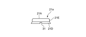
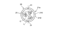
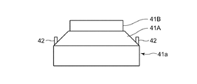
- Embodiment 1 of this invention It is a front view of the fluid machine which concerns on Embodiment 1 of this invention. It is a fragmentary longitudinal cross-section which shows the inside of the said fluid machine. It is an expanded sectional view which shows the airtight terminal attachment part of the said fluid machine. It is a side view which shows the metal case of the airtight terminal of the said fluid machine. It is a top view which shows the airtight terminal of the said fluid machine. It is a front view which shows the welding jig used for the said fluid machine. It is a side view of the welding jig. It is a top view which shows the state which mounted
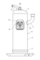
- FIG. 1 is a front view of a fluid machine according to Embodiment 1 of the present invention
- FIG. 2 is a partial longitudinal sectional view showing the inside of the fluid machine
- FIG. 3 is an enlarged sectional view showing an airtight terminal mounting portion of the fluid machine.
- the fluid machine according to the first embodiment is obtained by improving the positioning method during welding of the hermetic terminal.
- a scroll compressor that has an orbiting scroll and is used in a refrigerant circuit such as an air conditioner is exemplified as a fluid machine.
- the scroll compressor as a fluid machine includes a sealed container 14 having a fluid suction port 17A and a fluid discharge port 18A, and a fluid (refrigerant gas) disposed in the sealed container 14 and driven and driven into the sealed container 14 from the fluid suction port 17A.
- a fluid refrigerant gas
- the sealed container 14 is formed in a sealed shape by welding the upper end plate 11 to the upper end edge of the cylindrical container body 12 and welding the lower end plate 13 to the lower end edge of the container body 12.
- a suction pipe 17 is connected to the fluid suction port 17A of the sealed container 14, and a discharge pipe 18 is connected to the fluid discharge port 18A.
- a rotary drive unit such as a rocking scroll in the compression mechanism 15 is connected to a rotary drive shaft 16 ⁇ / b> A of the electric motor 16.
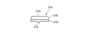
- the airtight terminal 26 includes a cup-shaped metal case 21a that is welded in a sealed manner to the mounting hole 19 of the sealed container 14, and a conductive material disposed in the burring portions 21B, 21B, and 21B formed in the metal case 21a. Attached to the metal case 21 with the pins 25, 25, 25, the insulating glass seal portions 24, 24, 24 loaded between the conductive pins 25 and the burring portions 21 B and holding the conductive pins 25. And a protective hood 23.
- the metal case 21a includes a flat disk-shaped bottom flat surface portion 21A, an outer surface portion 21E extending from the periphery of the bottom flat surface portion 21A, and a periphery of the outer surface portion 21E.
- An opening edge portion 21D extending in a taper shape and extending.
- the burring portions 21B, 21B, and 21B are formed on the bottom flat surface portion 21A.
- a pair of first positioning locking portions 31 and 31 are provided on the opening edge portion 21D of the metal case 21a. These first positioning locking portions 31, 31 are formed as concave notches, and are provided at opposing positions on a diagonal L passing through the cup cylinder C of the metal case 21a.
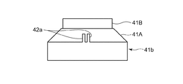
- the welding jig 41a is mounted in the metal case 21a of the hermetic terminal 26, and has a cylindrical shape that supports the back surface of the bottom flat surface portion 21A in the metal case 21a.
- the outer surface portion 41B and a tapered surface portion 41A that extends from the edge of the outer surface portion 41B and supports the back surface of the opening edge portion 21D of the metal case 21a.
- Three pin accommodating spaces 28, 28, 28 for accommodating the respective conductive pins 25 and the glass seal portion 24 are formed on the surface of the outer side surface portion 41B.
- second positioning locking portions 42 and 42 are erected at the position of the tapered surface portion 41A facing the opening edge portion 21D of the mounted metal case 21a.
- These second positioning locking portions 42 and 42 are formed as convex portions, are opposed to each other on a diagonal L passing through the cup cylinder C of the metal case 21a, and the welding jig 41a is in the metal case 21a. It is provided at a position where it engages with the first positioning locking portions 31, 31 of the metal case 21 a when mounted at a specified position for welding.
- the electric motor 16 is supplied with power from an external power source via the hermetic terminal 26 and the electric wire 20. Then, by driving the compression mechanism 15, the refrigerant is sucked into the sealed container 14 from the suction pipe 17 connected to the refrigeration cycle through the fluid suction port 17 ⁇ / b> A and pressurized by the compression mechanism 15, and then the fluid discharge port. It is sent out to the refrigeration cycle from the discharge pipe 18 from 18A.
- the fluid machine is, for example, a refrigerant compressor
- the refrigerant and the refrigerating machine oil circulate in the hermetic container 14.
- the insulating property of the airtight terminal 26 is ensured by applying a silicon coating on the surface to prevent the refrigerant and refrigerator oil from adhering to the surface of the glass seal portion 24.
- the first positioning locking portion 31 of the opening edge 21D of the metal case 21 is replaced with the second positioning locking portion of the welding jig 41 during welding.
- the metal case 21 and the welding jig 41 can be accurately positioned and fixed at the specified positions.
- the fixing by the welding jig 41 of the glass-insulated burring part 21B of the bottom flat part 21A of the metal case 21 as in the prior art can be eliminated.
- the welding length can be stabilized, the quality of the pressure strength of the entire sealed container 14 can be improved.
- the metal case 21a is provided with the concave first positioning locking portions 31 and 31, and the convex second positioning locking portions 42 and 42 engaged therewith are provided on the welding jig 41a.
- the convex first positioning locking portion may be provided on the metal case 21a, and the concave second positioning locking portion that engages with the first positioning locking portion may be provided on the welding jig 41a.
- Embodiment 2 FIG.
- the first positioning locking portions 31 and 31 of the hermetic terminal 26 are provided at positions on the diagonal L passing through the cup cylinder C of the metal case 21a.
- the angles are not two points on the diagonal L. You may form in the position.
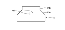
- FIGS. Such a second embodiment is shown in FIGS.
- the basic configuration of the airtight terminal 26a and the welding jig 41b according to the second embodiment is the same as that of the airtight terminal 26 and the welding jig 41a shown in the first embodiment.
- the place where the airtight terminal 26a and the welding jig 41b according to the second embodiment are different from those of the first embodiment is that the first positioning locking portions 31a and 31a of the metal case 21b in the airtight terminal 26a are Corresponding to being provided at a position (that is, a non-diagonal position) other than on the diagonal line L passing through the cup cylinder C of the metal case 21b as a convex portion, and corresponding to the arrangement of the first positioning locking portions 31a and 31a.
- the second positioning locking portions 42a and 42a are provided as opposing portions at positions other than the diagonal line L passing through the cup cylinder center C of the welding jig 41b as concave portions.
- locking part 42a is the arrangement
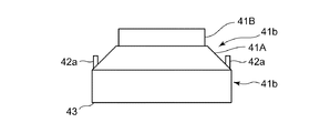
- the metal case 21b and the welding jig 41b of the hermetic terminal 26a are provided with concavities and convexities that are engaged for positioning.
- the positioning at the time of welding can be performed not at the glass seal portion 24 and the conductive pin 25 but at the metal case 21b. Therefore, unlike the fluid machine described in Patent Document 1, the fluid machine according to Embodiment 2 can avoid damage to the glass seal portion 24 when welding the airtight terminal 26a to the sealed container 14, As with the first embodiment, the quality of the fluid machine can be improved.
- the fluid machine according to the second embodiment can reliably prevent the reverse phase attachment from being reversed by 180 degrees by the engagement of the concavo-convex portion at the non-diagonal position. For this reason, the fluid machine according to the second embodiment can further improve the quality with respect to the deterioration of the insulation resistance of the terminal portion of the fluid machine as compared with the fluid machine shown in the first embodiment.
- convex first positioning locking portions 31a, 31a are provided on the metal case 21b, and concave positioning second positioning locking portions 42a, 42a, 42a, 42a are formed.
- a concave first positioning locking portion may be provided on the metal case 21b, and a convex second positioning locking portion may be provided on the welding jig 41b.
- the fluid applied to the fluid machine of the present invention is not limited to the refrigerant exemplified in the first and second embodiments, and may be a gas such as air or carbon dioxide, or a liquid such as water or alcohol. .
Landscapes
- Engineering & Computer Science (AREA)
- Power Engineering (AREA)
- Mechanical Engineering (AREA)
- General Engineering & Computer Science (AREA)
- Compressor (AREA)
- Applications Or Details Of Rotary Compressors (AREA)
Abstract
L'invention vise à procurer une machine à fluide conçue de telle sorte qu'une longueur de soudure suffisante est assurée entre un boîtier métallique de borne étanche à l'air et un trou de montage dans un récipient hermétique afin d'améliorer la fiabilité de résistance à la pression. A cet effet, l'invention porte sur une machine à fluide, laquelle machine comprend un récipient hermétique, un mécanisme de compression, un moteur électrique, et une borne étanche à l'air (26). Un gabarit de soudage (41a) qui est installé à l'intérieur de l'enceinte métallique (21a) de la borne étanche à l'air (26) et qui positionne et qui soutient le boîtier métallique (21a) est utilisé lors du soudage du boîtier métallique (21a) à un trou de montage dans le récipient hermétique. Une première section de prise de positionnement (31) est disposée au bord d'ouverture (21D) du boîtier métallique (21a). Une seconde section de prise de positionnement (42) qui vient en prise avec la première section de prise de positionnement (31) du boîtier métallique (21a) de manière à être apte à se désaccoupler de cette dernière est disposée sur le gabarit de soudage (41a) en une position faisant face au bord d'ouverture (21D) du boîtier métallique (21a).
Priority Applications (2)
| Application Number | Priority Date | Filing Date | Title |
|---|---|---|---|
| JP2017508785A JP6366819B2 (ja) | 2015-03-27 | 2015-03-27 | 流体機械 |
| PCT/JP2015/001771 WO2016157236A1 (fr) | 2015-03-27 | 2015-03-27 | Machine à fluide |
Applications Claiming Priority (1)
| Application Number | Priority Date | Filing Date | Title |
|---|---|---|---|
| PCT/JP2015/001771 WO2016157236A1 (fr) | 2015-03-27 | 2015-03-27 | Machine à fluide |
Publications (1)
| Publication Number | Publication Date |
|---|---|
| WO2016157236A1 true WO2016157236A1 (fr) | 2016-10-06 |
Family
ID=57004039
Family Applications (1)
| Application Number | Title | Priority Date | Filing Date |
|---|---|---|---|
| PCT/JP2015/001771 Ceased WO2016157236A1 (fr) | 2015-03-27 | 2015-03-27 | Machine à fluide |
Country Status (2)
| Country | Link |
|---|---|
| JP (1) | JP6366819B2 (fr) |
| WO (1) | WO2016157236A1 (fr) |
Citations (8)
| Publication number | Priority date | Publication date | Assignee | Title |
|---|---|---|---|---|
| JPH03273844A (ja) * | 1990-03-21 | 1991-12-05 | Tecumseh Prod Co | 可融リンク付き端子ピン組立品のある密封端子およびそれを含むモータ・コンプレッサ装置 |
| JPH04132885A (ja) * | 1990-09-20 | 1992-05-07 | Nec Kansai Ltd | 気密端子及び圧縮機 |
| JPH11303744A (ja) * | 1998-04-20 | 1999-11-02 | Matsushita Electric Ind Co Ltd | 密閉型圧縮機 |
| US20020060217A1 (en) * | 2000-11-23 | 2002-05-23 | Lg Electronics Inc. | Welding apparatus and method thereof for hermetic compressor |
| JP2003148344A (ja) * | 2001-11-09 | 2003-05-21 | Mitsubishi Electric Corp | 冷媒圧縮機及び耐圧容器 |
| JP2003161262A (ja) * | 2001-11-26 | 2003-06-06 | Sanyo Electric Co Ltd | 圧縮機 |
| JP2005307798A (ja) * | 2004-04-20 | 2005-11-04 | Matsushita Electric Ind Co Ltd | 密閉型電動圧縮機 |
| US20110008193A1 (en) * | 2009-07-13 | 2011-01-13 | Samsung Gwangju Electronics Co., Ltd. | Hermetic type compressor |
-
2015
- 2015-03-27 WO PCT/JP2015/001771 patent/WO2016157236A1/fr not_active Ceased
- 2015-03-27 JP JP2017508785A patent/JP6366819B2/ja not_active Expired - Fee Related
Patent Citations (8)
| Publication number | Priority date | Publication date | Assignee | Title |
|---|---|---|---|---|
| JPH03273844A (ja) * | 1990-03-21 | 1991-12-05 | Tecumseh Prod Co | 可融リンク付き端子ピン組立品のある密封端子およびそれを含むモータ・コンプレッサ装置 |
| JPH04132885A (ja) * | 1990-09-20 | 1992-05-07 | Nec Kansai Ltd | 気密端子及び圧縮機 |
| JPH11303744A (ja) * | 1998-04-20 | 1999-11-02 | Matsushita Electric Ind Co Ltd | 密閉型圧縮機 |
| US20020060217A1 (en) * | 2000-11-23 | 2002-05-23 | Lg Electronics Inc. | Welding apparatus and method thereof for hermetic compressor |
| JP2003148344A (ja) * | 2001-11-09 | 2003-05-21 | Mitsubishi Electric Corp | 冷媒圧縮機及び耐圧容器 |
| JP2003161262A (ja) * | 2001-11-26 | 2003-06-06 | Sanyo Electric Co Ltd | 圧縮機 |
| JP2005307798A (ja) * | 2004-04-20 | 2005-11-04 | Matsushita Electric Ind Co Ltd | 密閉型電動圧縮機 |
| US20110008193A1 (en) * | 2009-07-13 | 2011-01-13 | Samsung Gwangju Electronics Co., Ltd. | Hermetic type compressor |
Also Published As
| Publication number | Publication date |
|---|---|
| JP6366819B2 (ja) | 2018-08-01 |
| JPWO2016157236A1 (ja) | 2017-10-12 |
Similar Documents
| Publication | Publication Date | Title |
|---|---|---|
| US20110158833A1 (en) | Electric compressor | |
| JP2005155369A (ja) | 電動圧縮機 | |
| JPWO2018154689A1 (ja) | 圧縮機 | |
| CN105683572B (zh) | 压缩机及压缩机的制造方法 | |
| JP2007255332A (ja) | 圧縮機 | |
| JP6366819B2 (ja) | 流体機械 | |
| WO2020202493A1 (fr) | Raccord métallique, compresseur de type hermétique et procédé de fabrication dudit compresseur | |
| JP6497365B2 (ja) | 圧力容器、圧力容器を備えた圧縮機及び圧力容器の製造方法 | |
| JP6391953B2 (ja) | 下部フレームを備えた圧縮機及びその製造方法 | |
| JP6314610B2 (ja) | 圧縮機の溶接方法 | |
| JP6416645B2 (ja) | 密閉型圧縮機 | |
| JP3843917B2 (ja) | 圧縮機及びその製造方法 | |
| JP2003148344A (ja) | 冷媒圧縮機及び耐圧容器 | |
| US10495091B2 (en) | Rotary compressor having an injection connecting pipe that extends to an upper portion of a compressor housing and that is linked to an injection pipe via an injection pipe taking-out portion | |
| CN113423953B (zh) | 包括具有通过双面焊接t形接头固定的安装基座和圆柱形边沿的底板的涡旋式压缩机 | |
| KR200265571Y1 (ko) | 받침대를 갖춘 압축기 조립체 | |
| JP7312967B2 (ja) | ステータ、モータおよび圧縮機 | |
| CN105896764A (zh) | 密闭型电动压缩机 | |
| JP6076819B2 (ja) | 密閉型圧縮機 | |
| JP6107785B2 (ja) | 圧縮機の製造方法、および圧縮機 | |
| JP5206635B2 (ja) | 電動圧縮機およびその製造方法 | |
| JP4395013B2 (ja) | 密閉型圧縮機 | |
| JP5246127B2 (ja) | 密閉型圧縮機 | |
| JP2005220762A (ja) | 圧縮機 | |
| WO2018138772A1 (fr) | Compresseur de type fermé |
Legal Events
| Date | Code | Title | Description |
|---|---|---|---|
| 121 | Ep: the epo has been informed by wipo that ep was designated in this application |
Ref document number: 15887394 Country of ref document: EP Kind code of ref document: A1 |
|
| ENP | Entry into the national phase |
Ref document number: 2017508785 Country of ref document: JP Kind code of ref document: A |
|
| NENP | Non-entry into the national phase |
Ref country code: DE |
|
| 122 | Ep: pct application non-entry in european phase |
Ref document number: 15887394 Country of ref document: EP Kind code of ref document: A1 |