WO2016157263A1 - Dispositif d'alimentation et dispositif électronique équipé d'un tel dispositif - Google Patents
Dispositif d'alimentation et dispositif électronique équipé d'un tel dispositif Download PDFInfo
- Publication number
- WO2016157263A1 WO2016157263A1 PCT/JP2015/005566 JP2015005566W WO2016157263A1 WO 2016157263 A1 WO2016157263 A1 WO 2016157263A1 JP 2015005566 W JP2015005566 W JP 2015005566W WO 2016157263 A1 WO2016157263 A1 WO 2016157263A1
- Authority
- WO
- WIPO (PCT)
- Prior art keywords
- power supply
- supply device
- battery case
- frame
- battery
- Prior art date
- Legal status (The legal status is an assumption and is not a legal conclusion. Google has not performed a legal analysis and makes no representation as to the accuracy of the status listed.)
- Ceased
Links
Images






Classifications
-
- H—ELECTRICITY
- H01—ELECTRIC ELEMENTS
- H01M—PROCESSES OR MEANS, e.g. BATTERIES, FOR THE DIRECT CONVERSION OF CHEMICAL ENERGY INTO ELECTRICAL ENERGY
- H01M10/00—Secondary cells; Manufacture thereof
- H01M10/60—Heating or cooling; Temperature control
- H01M10/65—Means for temperature control structurally associated with the cells
- H01M10/656—Means for temperature control structurally associated with the cells characterised by the type of heat-exchange fluid
- H01M10/6561—Gases
- H01M10/6563—Gases with forced flow, e.g. by blowers
-
- B—PERFORMING OPERATIONS; TRANSPORTING
- B60—VEHICLES IN GENERAL
- B60L—PROPULSION OF ELECTRICALLY-PROPELLED VEHICLES; SUPPLYING ELECTRIC POWER FOR AUXILIARY EQUIPMENT OF ELECTRICALLY-PROPELLED VEHICLES; ELECTRODYNAMIC BRAKE SYSTEMS FOR VEHICLES IN GENERAL; MAGNETIC SUSPENSION OR LEVITATION FOR VEHICLES; MONITORING OPERATING VARIABLES OF ELECTRICALLY-PROPELLED VEHICLES; ELECTRIC SAFETY DEVICES FOR ELECTRICALLY-PROPELLED VEHICLES
- B60L50/00—Electric propulsion with power supplied within the vehicle
- B60L50/50—Electric propulsion with power supplied within the vehicle using propulsion power supplied by batteries or fuel cells
- B60L50/60—Electric propulsion with power supplied within the vehicle using propulsion power supplied by batteries or fuel cells using power supplied by batteries
- B60L50/64—Constructional details of batteries specially adapted for electric vehicles
-
- H—ELECTRICITY
- H01—ELECTRIC ELEMENTS
- H01M—PROCESSES OR MEANS, e.g. BATTERIES, FOR THE DIRECT CONVERSION OF CHEMICAL ENERGY INTO ELECTRICAL ENERGY
- H01M10/00—Secondary cells; Manufacture thereof
- H01M10/42—Methods or arrangements for servicing or maintenance of secondary cells or secondary half-cells
- H01M10/425—Structural combination with electronic components, e.g. electronic circuits integrated to the outside of the casing
-
- H—ELECTRICITY
- H01—ELECTRIC ELEMENTS
- H01M—PROCESSES OR MEANS, e.g. BATTERIES, FOR THE DIRECT CONVERSION OF CHEMICAL ENERGY INTO ELECTRICAL ENERGY
- H01M10/00—Secondary cells; Manufacture thereof
- H01M10/42—Methods or arrangements for servicing or maintenance of secondary cells or secondary half-cells
- H01M10/425—Structural combination with electronic components, e.g. electronic circuits integrated to the outside of the casing
- H01M10/4257—Smart batteries, e.g. electronic circuits inside the housing of the cells or batteries
-
- H—ELECTRICITY
- H01—ELECTRIC ELEMENTS
- H01M—PROCESSES OR MEANS, e.g. BATTERIES, FOR THE DIRECT CONVERSION OF CHEMICAL ENERGY INTO ELECTRICAL ENERGY
- H01M10/00—Secondary cells; Manufacture thereof
- H01M10/60—Heating or cooling; Temperature control
- H01M10/61—Types of temperature control
- H01M10/613—Cooling or keeping cold
-
- H—ELECTRICITY
- H01—ELECTRIC ELEMENTS
- H01M—PROCESSES OR MEANS, e.g. BATTERIES, FOR THE DIRECT CONVERSION OF CHEMICAL ENERGY INTO ELECTRICAL ENERGY
- H01M10/00—Secondary cells; Manufacture thereof
- H01M10/60—Heating or cooling; Temperature control
- H01M10/62—Heating or cooling; Temperature control specially adapted for specific applications
- H01M10/625—Vehicles
-
- H—ELECTRICITY
- H01—ELECTRIC ELEMENTS
- H01M—PROCESSES OR MEANS, e.g. BATTERIES, FOR THE DIRECT CONVERSION OF CHEMICAL ENERGY INTO ELECTRICAL ENERGY
- H01M10/00—Secondary cells; Manufacture thereof
- H01M10/60—Heating or cooling; Temperature control
- H01M10/64—Heating or cooling; Temperature control characterised by the shape of the cells
- H01M10/647—Prismatic or flat cells, e.g. pouch cells
-
- H—ELECTRICITY
- H01—ELECTRIC ELEMENTS
- H01M—PROCESSES OR MEANS, e.g. BATTERIES, FOR THE DIRECT CONVERSION OF CHEMICAL ENERGY INTO ELECTRICAL ENERGY
- H01M10/00—Secondary cells; Manufacture thereof
- H01M10/60—Heating or cooling; Temperature control
- H01M10/65—Means for temperature control structurally associated with the cells
- H01M10/655—Solid structures for heat exchange or heat conduction
- H01M10/6556—Solid parts with flow channel passages or pipes for heat exchange
- H01M10/6557—Solid parts with flow channel passages or pipes for heat exchange arranged between the cells
-
- H—ELECTRICITY
- H01—ELECTRIC ELEMENTS
- H01M—PROCESSES OR MEANS, e.g. BATTERIES, FOR THE DIRECT CONVERSION OF CHEMICAL ENERGY INTO ELECTRICAL ENERGY
- H01M10/00—Secondary cells; Manufacture thereof
- H01M10/60—Heating or cooling; Temperature control
- H01M10/66—Heat-exchange relationships between the cells and other systems, e.g. central heating systems or fuel cells
- H01M10/667—Heat-exchange relationships between the cells and other systems, e.g. central heating systems or fuel cells the system being an electronic component, e.g. a CPU, an inverter or a capacitor
-
- H—ELECTRICITY
- H01—ELECTRIC ELEMENTS
- H01M—PROCESSES OR MEANS, e.g. BATTERIES, FOR THE DIRECT CONVERSION OF CHEMICAL ENERGY INTO ELECTRICAL ENERGY
- H01M50/00—Constructional details or processes of manufacture of the non-active parts of electrochemical cells other than fuel cells, e.g. hybrid cells
- H01M50/20—Mountings; Secondary casings or frames; Racks, modules or packs; Suspension devices; Shock absorbers; Transport or carrying devices; Holders
- H01M50/204—Racks, modules or packs for multiple batteries or multiple cells
-
- H—ELECTRICITY
- H01—ELECTRIC ELEMENTS
- H01M—PROCESSES OR MEANS, e.g. BATTERIES, FOR THE DIRECT CONVERSION OF CHEMICAL ENERGY INTO ELECTRICAL ENERGY
- H01M50/00—Constructional details or processes of manufacture of the non-active parts of electrochemical cells other than fuel cells, e.g. hybrid cells
- H01M50/20—Mountings; Secondary casings or frames; Racks, modules or packs; Suspension devices; Shock absorbers; Transport or carrying devices; Holders
- H01M50/218—Mountings; Secondary casings or frames; Racks, modules or packs; Suspension devices; Shock absorbers; Transport or carrying devices; Holders characterised by the material
- H01M50/22—Mountings; Secondary casings or frames; Racks, modules or packs; Suspension devices; Shock absorbers; Transport or carrying devices; Holders characterised by the material of the casings or racks
- H01M50/222—Inorganic material
- H01M50/224—Metals
-
- H—ELECTRICITY
- H01—ELECTRIC ELEMENTS
- H01M—PROCESSES OR MEANS, e.g. BATTERIES, FOR THE DIRECT CONVERSION OF CHEMICAL ENERGY INTO ELECTRICAL ENERGY
- H01M50/00—Constructional details or processes of manufacture of the non-active parts of electrochemical cells other than fuel cells, e.g. hybrid cells
- H01M50/20—Mountings; Secondary casings or frames; Racks, modules or packs; Suspension devices; Shock absorbers; Transport or carrying devices; Holders
- H01M50/218—Mountings; Secondary casings or frames; Racks, modules or packs; Suspension devices; Shock absorbers; Transport or carrying devices; Holders characterised by the material
- H01M50/22—Mountings; Secondary casings or frames; Racks, modules or packs; Suspension devices; Shock absorbers; Transport or carrying devices; Holders characterised by the material of the casings or racks
- H01M50/227—Organic material
-
- H—ELECTRICITY
- H01—ELECTRIC ELEMENTS
- H01M—PROCESSES OR MEANS, e.g. BATTERIES, FOR THE DIRECT CONVERSION OF CHEMICAL ENERGY INTO ELECTRICAL ENERGY
- H01M50/00—Constructional details or processes of manufacture of the non-active parts of electrochemical cells other than fuel cells, e.g. hybrid cells
- H01M50/20—Mountings; Secondary casings or frames; Racks, modules or packs; Suspension devices; Shock absorbers; Transport or carrying devices; Holders
- H01M50/233—Mountings; Secondary casings or frames; Racks, modules or packs; Suspension devices; Shock absorbers; Transport or carrying devices; Holders characterised by physical properties of casings or racks, e.g. dimensions
- H01M50/24—Mountings; Secondary casings or frames; Racks, modules or packs; Suspension devices; Shock absorbers; Transport or carrying devices; Holders characterised by physical properties of casings or racks, e.g. dimensions adapted for protecting batteries from their environment, e.g. from corrosion
-
- H—ELECTRICITY
- H01—ELECTRIC ELEMENTS
- H01M—PROCESSES OR MEANS, e.g. BATTERIES, FOR THE DIRECT CONVERSION OF CHEMICAL ENERGY INTO ELECTRICAL ENERGY
- H01M50/00—Constructional details or processes of manufacture of the non-active parts of electrochemical cells other than fuel cells, e.g. hybrid cells
- H01M50/20—Mountings; Secondary casings or frames; Racks, modules or packs; Suspension devices; Shock absorbers; Transport or carrying devices; Holders
- H01M50/249—Mountings; Secondary casings or frames; Racks, modules or packs; Suspension devices; Shock absorbers; Transport or carrying devices; Holders specially adapted for aircraft or vehicles, e.g. cars or trains
-
- H—ELECTRICITY
- H01—ELECTRIC ELEMENTS
- H01M—PROCESSES OR MEANS, e.g. BATTERIES, FOR THE DIRECT CONVERSION OF CHEMICAL ENERGY INTO ELECTRICAL ENERGY
- H01M50/00—Constructional details or processes of manufacture of the non-active parts of electrochemical cells other than fuel cells, e.g. hybrid cells
- H01M50/20—Mountings; Secondary casings or frames; Racks, modules or packs; Suspension devices; Shock absorbers; Transport or carrying devices; Holders
- H01M50/271—Lids or covers for the racks or secondary casings
- H01M50/273—Lids or covers for the racks or secondary casings characterised by the material
- H01M50/276—Inorganic material
-
- H—ELECTRICITY
- H01—ELECTRIC ELEMENTS
- H01M—PROCESSES OR MEANS, e.g. BATTERIES, FOR THE DIRECT CONVERSION OF CHEMICAL ENERGY INTO ELECTRICAL ENERGY
- H01M50/00—Constructional details or processes of manufacture of the non-active parts of electrochemical cells other than fuel cells, e.g. hybrid cells
- H01M50/20—Mountings; Secondary casings or frames; Racks, modules or packs; Suspension devices; Shock absorbers; Transport or carrying devices; Holders
- H01M50/284—Mountings; Secondary casings or frames; Racks, modules or packs; Suspension devices; Shock absorbers; Transport or carrying devices; Holders with incorporated circuit boards, e.g. printed circuit boards [PCB]
-
- H—ELECTRICITY
- H01—ELECTRIC ELEMENTS
- H01M—PROCESSES OR MEANS, e.g. BATTERIES, FOR THE DIRECT CONVERSION OF CHEMICAL ENERGY INTO ELECTRICAL ENERGY
- H01M2220/00—Batteries for particular applications
- H01M2220/20—Batteries in motive systems, e.g. vehicle, ship, plane
-
- H—ELECTRICITY
- H01—ELECTRIC ELEMENTS
- H01M—PROCESSES OR MEANS, e.g. BATTERIES, FOR THE DIRECT CONVERSION OF CHEMICAL ENERGY INTO ELECTRICAL ENERGY
- H01M50/00—Constructional details or processes of manufacture of the non-active parts of electrochemical cells other than fuel cells, e.g. hybrid cells
- H01M50/20—Mountings; Secondary casings or frames; Racks, modules or packs; Suspension devices; Shock absorbers; Transport or carrying devices; Holders
- H01M50/262—Mountings; Secondary casings or frames; Racks, modules or packs; Suspension devices; Shock absorbers; Transport or carrying devices; Holders with fastening means, e.g. locks
-
- H—ELECTRICITY
- H01—ELECTRIC ELEMENTS
- H01M—PROCESSES OR MEANS, e.g. BATTERIES, FOR THE DIRECT CONVERSION OF CHEMICAL ENERGY INTO ELECTRICAL ENERGY
- H01M50/00—Constructional details or processes of manufacture of the non-active parts of electrochemical cells other than fuel cells, e.g. hybrid cells
- H01M50/20—Mountings; Secondary casings or frames; Racks, modules or packs; Suspension devices; Shock absorbers; Transport or carrying devices; Holders
- H01M50/296—Mountings; Secondary casings or frames; Racks, modules or packs; Suspension devices; Shock absorbers; Transport or carrying devices; Holders characterised by terminals of battery packs
-
- Y—GENERAL TAGGING OF NEW TECHNOLOGICAL DEVELOPMENTS; GENERAL TAGGING OF CROSS-SECTIONAL TECHNOLOGIES SPANNING OVER SEVERAL SECTIONS OF THE IPC; TECHNICAL SUBJECTS COVERED BY FORMER USPC CROSS-REFERENCE ART COLLECTIONS [XRACs] AND DIGESTS
- Y02—TECHNOLOGIES OR APPLICATIONS FOR MITIGATION OR ADAPTATION AGAINST CLIMATE CHANGE
- Y02E—REDUCTION OF GREENHOUSE GAS [GHG] EMISSIONS, RELATED TO ENERGY GENERATION, TRANSMISSION OR DISTRIBUTION
- Y02E60/00—Enabling technologies; Technologies with a potential or indirect contribution to GHG emissions mitigation
- Y02E60/10—Energy storage using batteries
-
- Y—GENERAL TAGGING OF NEW TECHNOLOGICAL DEVELOPMENTS; GENERAL TAGGING OF CROSS-SECTIONAL TECHNOLOGIES SPANNING OVER SEVERAL SECTIONS OF THE IPC; TECHNICAL SUBJECTS COVERED BY FORMER USPC CROSS-REFERENCE ART COLLECTIONS [XRACs] AND DIGESTS
- Y02—TECHNOLOGIES OR APPLICATIONS FOR MITIGATION OR ADAPTATION AGAINST CLIMATE CHANGE
- Y02T—CLIMATE CHANGE MITIGATION TECHNOLOGIES RELATED TO TRANSPORTATION
- Y02T10/00—Road transport of goods or passengers
- Y02T10/60—Other road transportation technologies with climate change mitigation effect
- Y02T10/70—Energy storage systems for electromobility, e.g. batteries
Definitions
- the present invention relates to a power supply device and a vehicle including the power supply device, and more particularly to a power supply device for a motor that is mounted on an electric vehicle such as a hybrid vehicle, an electric vehicle, and an electric motorcycle to drive the vehicle.
- an electric vehicle such as a hybrid vehicle, an electric vehicle, and an electric motorcycle to drive the vehicle.
- a power supply device in which a plurality of secondary battery cells are connected in series or in parallel is used for in-vehicle applications.
- a structure in which a high voltage component such as a module such as a secondary battery cell or a circuit board is housed and fixed in a metal frame or metal case is mainly used.
- a power supply device for a vehicle is required to be strong enough to withstand vibrations and impacts while holding heavy modules and high-voltage components.
- a metal member is used. It was common to construct a frame or case.
- the case may be made of resin.
- the weight can be reduced, there is a problem that the strength becomes weak and sufficient resistance cannot be obtained.
- An object of the present invention is to provide a power supply device that is lightweight while increasing rigidity.
- the battery case A power supply apparatus comprising: a resin battery case that houses a body and a circuit board; a metal lower frame that covers a bottom surface of the battery case; and a metal upper frame that covers an upper surface of the battery case,
- the battery case has a waterproof structure, and the battery case can be sandwiched by connecting the upper frame and the lower frame.
- the battery case is made of a resin that is easy to mold even with a relatively complicated shape, thereby making it easy to achieve a waterproof structure, while ensuring the strength by covering the upper and lower surfaces with a metal frame.
- EMC electromagnetic noise
- the upper frame includes a first frame and a second frame, the first frame and the second frame are spaced apart from each other, and the first frame and the second frame are separated from each other.
- An exposed region in which a part of the battery case is exposed can be provided.
- the external shape of the power supply device is a rectangular shape extending in one direction in plan view, and the exposed region can be provided at the center in the longitudinal direction.
- the battery pack further includes a DC / DC converter for converting the output of the battery stack into a predetermined voltage, and the DC / DC converter is connected to the battery case. It can arrange
- the DC / DC converter is built in the battery case to be compact, the DC / DC converter is protected by the first frame, and the heat generated by the DC / DC converter is supplied via the first frame.
- the heat radiation performance for radiating heat to the outside of the device can be enhanced.
- the cooling structure of the battery stack can also be used for cooling the DC / DC converter, so that the structure can be further downsized.
- the circuit board can be arranged in an area of the battery case covered with the second frame.
- the circuit board can be shielded with the metal second frame, and the heat dissipation can be enhanced through the second frame.
- the battery case has an intake port for taking in the cooling gas and an exhaust port for discharging the heat-exchanged cooling gas. And at least one of the exhaust port may be provided in the exposed region.
- an opening can be formed in at least one of the intake port and the exhaust port provided in the exposed area so as to protrude from the surface of the battery case.
- the other of the intake port and the exhaust port can be opened on the side surface of the battery case.
- the exhaust port can be provided in the exposed area.
- the lower frame and the upper frame can project a fixing piece for fixing the power supply device.
- the battery case can be divided into an upper case and a lower case, and an elastic member can be disposed on a joint surface between the upper case and the lower case.
- one or more recesses having a recessed surface can be formed in the exposed region of the battery case.
- the recess can be used for positioning and fixing.
- the recess includes a first recess provided on the upper surface side of the battery case and a first recess provided on the lower surface side of the battery case in the exposed region of the battery case. And two recesses.
- the concave portions are provided on the upper and lower surfaces of the battery case, so that the battery case can be positioned from both sides and fixed more stably.
- the battery case houses a plurality of the battery stacks, and the battery stacks are arranged side by side in the longitudinal direction of the battery case.
- the said recessed part can be formed between the said battery laminated bodies arrange
- the lower frame can be formed by welding a plurality of metal plates.
- the above power supply device can be provided.
- a power supply device 100 according to Embodiment 1 of the present invention is shown in FIGS.
- the power supply device 100 shown in these drawings shows an example of an in-vehicle power supply device.
- the power supply device 100 is mounted mainly on an electric vehicle such as a hybrid vehicle or an electric vehicle, and is used as a power source for supplying power to the vehicle running motor to drive the vehicle.
- the power supply device of the present invention can be used for an electric vehicle other than a hybrid vehicle or an electric vehicle, and can also be used for an application requiring a high output other than an electric vehicle. (Power supply device 100)
- the external appearance of the power supply device 100 has a substantially box shape extending in one direction as shown in FIGS.
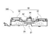
- the power supply device 100 has a structure in which the upper and lower sides of the resin battery case 20 are covered with a metal frame 30.
- the metal frame 30 has a metal lower frame 35 that covers the bottom surface of the battery case 20 and a metal upper frame 34 that covers the top surface of the battery case 20.
- the resin battery case 20 houses the battery assembly 10 therein.
- the battery assembly 10 includes a battery stack 11 in which the secondary battery cells 1 are stacked, a circuit board 42, and the like.
- the battery case 20 is made of resin, it can be formed into various shapes, so that a waterproof structure can be easily realized.
- the mechanical strength is ensured by covering the upper and lower surfaces with the metal frame 30. Further, by covering the periphery with the metal frame 30, it is possible to improve heat dissipation and improve noise resistance of the electronic circuit in the battery case by the shielding effect of the metal plate. (Metal frame 30)
- the upper and lower surfaces of the battery case 20 are held between the upper frame 34 and the lower frame 35. For this reason, the upper frame 34 and the lower frame 35 are connected by screws or the like via the fixing pieces 36 on the side surfaces.
- the upper frame 34 and the lower frame 35 are formed by bending a metal plate. Moreover, in order to improve rigidity, the unevenness
- the metal plate can be made of high strength steel, general steel, stainless steel, aluminum alloy, magnesium alloy, etc., which are excellent in rigidity and heat conduction, or a combination thereof.
- the lower frame 35 is configured by welding a plurality of metal plates. Note that the lower frame 35 is not necessarily welded with a plurality of metal plates, and can be processed by integral molding by pressing.
- the metal frame 30 does not cover the entire periphery of the battery case 20 but covers only a necessary part. 6 and 7, the lower frame 35 of the metal frame 30 has a bottomed box shape with the upper surface open, and the upper frame 34 has a shape that exposes a part of the upper surface of the battery case 20. . Further, the side surface of the battery case 20 may be opened without being covered with the metal frame 30. In this way, by partially covering the battery case 20 with the metal frame 30, a metal plate is disposed in a portion where strength is required, while the metal plate is omitted in a region where strength is not required. The required area of the plate can be reduced, contributing to weight reduction and cost reduction. Further, in the exposed area where the metal plate is not covered, it is possible to reduce the thickness corresponding to the thickness of the metal plate.
- the upper frame 34 is divided into a first frame 31 and a second frame 32, and the first frame 31 and the second frame 32 are arranged apart from each other. Thereby, an exposed area 23 in which a part of the battery case 20 is exposed is formed between the first frame 31 and the second frame 32. In the exposed area 23, the thickness can be reduced.
- a portion corresponding to the lower surface of the seat ST where strength is required in a configuration in which the power supply device 100 is disposed across the lower surfaces of two adjacent seats ST of the vehicle, a portion corresponding to the lower surface of the seat ST where strength is required.
- the first frame 31 and the second frame 32 are respectively disposed, while the metal frame is omitted from the portion between them to secure a necessary space for arranging members and to efficiently use the in-vehicle space.
- the metal frame 30 having excellent thermal conductivity is disposed on the surface of the battery case 20 made of resin, and has a function as a heat sink.
- the metal frame 30 having excellent thermal conductivity is disposed on the surface of the battery case 20 made of resin, and has a function as a heat sink.
- first frame 31 and the second frame 32 there is an advantage that the metal frames 30 can be thermally separated.
- first heat source and the second heat source are present as the heat sources in the battery case 20, they are arranged apart from each other to ensure heat dissipation from each heat source.
- the first frame 31 and the second frame 32 are arranged at the positions of the first heat source and the second heat source, respectively, so that each metal frame 30 bears heat radiation from each heat source.
- the heat radiation from each heat source is more propagated to the metal frame 30 side through the battery case 20 than the heat radiation to the inside of the battery case 20, and the members inside the battery case 20 can be protected from heat generation.
- the heat generation amount of the first heat source is different from the heat generation amount of the second heat source, for example, when the heat generation amount of the first heat source is large, the heat generation of the first heat source is also transferred to the second heat source side. Since it is conceivable that the heat radiation from the heat source is inhibited, the heat radiation can be improved by thermally separating the two from the members having a large calorific value. In the examples of FIGS.
- the first frame 31 and the second frame 32 are respectively arranged at the ends in the longitudinal direction of the battery case 20, and the exposed region 23 is provided at the center in the longitudinal direction. Thereby, while arrange
- the metal frame 30 has a fixing piece 36 protruding outward, and the upper frame 34 and the lower frame 35 are fixed with bolts and nuts through screw holes opened in the fixing piece 36.
- the fixing pieces 36 are provided at four locations on the top, bottom, left, and right in plan view.
- the screw hole of the fixing piece 36 can be used for fixing the power supply device 100.
- the power supply device 100 is fixed to a vehicle using a screw hole. (Battery case 20)
- the battery case 20 is divided into an upper case 21 and a lower case 22 as shown in exploded perspective views of FIGS.
- the battery case 20 is divided into an upper case 21 and a lower case 22 as shown in exploded perspective views of FIGS.
- a resin material PP (polypropylene), PBT (polybutylene terephthalate), PA (polyamide / nylon (registered trademark)) or a composite material of those resins and glass fiber / glass beads, and carbon fiber resin are used. It can also be used.
- a resin-metal composite material or the like in which a metal mesh, a metal plate or the like is sandwiched between resins at the time of resin molding can be used.
- a fitting structure is provided at the joining interface where the upper case 21 and the lower case 22 are joined. Thereby, airtightness is improved. Furthermore, further waterproofness can be achieved by arranging the elastic member 24 in the fitting structure. In the example of FIG. 7, packing is interposed as an elastic member 24 at the joint interface between the upper case 21 and the lower case 22. In this way, the battery case 20 is waterproofed, and the secondary battery cell 1 and the electronic circuit inside the battery case 20 are protected from an unintended short circuit.
- the battery stack 11, the circuit board 42, and the DC / DC converter 41 are accommodated.
- the battery stack 11 is formed by stacking a plurality of secondary battery cells 1 via an insulating separator. In addition, both end surfaces of the laminate are covered with end plates, and the end plates are fastened with a bind bar.
- the circuit board 42 is mounted with an electronic circuit such as a control circuit or a protection circuit that controls charging / discharging of the battery stack 11. (DC / DC converter 41)
- the DC / DC converter 41 is a member for converting the output of the battery stack 11 into a predetermined voltage.
- the DC / DC converter 41 converts the output of the battery stack 11 into 12V, 24V, or the like for power feeding to the electrical components of the vehicle.
- the arrangement space of the DC / DC converter 41 that has been conventionally arranged as a separate member is unnecessary, which contributes to space saving.
- the cooling mechanism for the battery stack 11 and the like in the battery case 20 can also be used for the cooling of the DC / DC converter 41, so that the cooling mechanism for the DC / DC converter that has been conventionally required is also omitted.
- the structure can be simplified, downsized, and the cost can be reduced.
- the DC / DC converter 41 is disposed so as to overlap an area covered with the first frame 31 in the battery case 20.
- the shape of the first frame 31, the internal structure of the battery case 20, the size and arrangement of the DC / DC converter 41 are arranged in advance so that the DC / DC converter 41 is positioned immediately below the first frame 31. Etc. are designed. In this way, the DC / DC converter 41 is mechanically protected by the first frame 31 and the heat generated by the DC / DC converter 41 can be efficiently radiated to the outside of the power supply device via the first frame 31. . It is preferable to arrange the DC / DC converter 41 so that it completely fits in the area covered with the first frame 31.
- the first frame and the DC / DC converter are arranged so as to overlap in a plan view of the battery case, even if a part of the DC / DC converter partially protrudes from the first frame. Good.
- a circuit board 42 is disposed in the area covered with the second frame 32. Thereby, the heat generated by the circuit group mounted on the circuit board 42 can be radiated through the second frame 32. Moreover, by covering the circuit board 42 with the metal second frame 32, a shielding effect for the electronic circuit mounted on the circuit board 42 can be obtained, and noise resistance can be improved.
- the DC / DC converter 41 is disposed on the first frame 31 side and the circuit board 42 is disposed on the second frame 32 side.
- the present invention is not limited to this configuration. It goes without saying that a circuit board may be arranged on one frame side and a DC / DC converter may be arranged on the second frame side. (Cooling structure)
- the battery case 20 is provided with a cooling mechanism for radiating heat from the internal members.
- a cooling mechanism for radiating heat from the internal members.
- an air cooling method is adopted in which a cooling gas is introduced from the outside, heat is exchanged in the battery case 20 and discharged.
- an intake port 51 for taking in the cooling gas and an exhaust port 52 for discharging the heat-exchanged cooling gas are opened in a part of the battery case 20.
- the intake port 51 and the exhaust port 52 is provided in the exposed region 23.
- the opening 54 does not have a metal frame, the opening 54 can be formed to protrude from the surface of the battery case 20.
- the opening area of the opening 54 can be increased to increase the air volume of the cooling gas, and the cooling capacity can be improved.
- the opening 54 is formed by projecting upward from the upper surface of the battery case 20 by a height d while opening the opening 54 on the back side of the battery case 20.
- Such an opening 54 is formed integrally with the upper case 21 of the battery case 20.
- the protruding portion is provided with a gradient on the upper surface of the battery case 20 so as to gradually increase toward the opening 54.
- the 1st frame 31 is provided in the structure which arrange
- frame 32 side can be employ
- either the intake port or the exhaust port is opened on the side surface side of the battery case 20.
- the opening on the side surface side of the battery case 20 is an intake port 51
- the opening formed on the back side of the exposed region 23 is an exhaust port 52.
- the lower frame 35 opens each corner corresponding to each intake port 51.
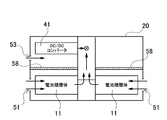
- the gas path through which the cooling gas flows into the battery case 20 and is exhausted is as shown in the schematic horizontal sectional view of FIG.
- four battery stacks 11 are arranged on the top, bottom, left, and right in the battery case 20, and the cooling gas sucked from the top and bottom of the left and right side surfaces in the figure is bent in the top and bottom directions to form the battery stack.
- the cooling gas of the plurality of battery stacks 11 is passed through to exchange heat, and this cooling gas is further guided to the center in the longitudinal direction.
- the cooling gas collected from the left and right to the center is discharged to the outside of the battery case 20 through an exhaust port 52 opened upward (back side).
- an air duct or the like is appropriately provided inside the battery case 20.
- a blower fan 56 is provided in the vicinity of the exhaust port 52. The blower fan 56 forcibly discharges the cooling gas introduced into the battery case 20 from the exhaust port 52 to the outside.
- a plurality of intake ports 51 are provided to supply cooling air to many parts, while the exhaust ports 52 are made common so that the number of blower fans 56 can be reduced.
- the cooling gas of the plurality of battery stacks 11 can be sucked into and exhausted from the battery case 20 with the single blower fan 56.
- the cooling gas is used for cooling other members in the battery case 20.
- it can be used to cool a circuit group mounted on a DC / DC converter 41 as a first heat source or a circuit board 42 as a second heat source.
- the first heat source inlet 53 is opened on the side surface of the battery case 20 on the side where the DC / DC converter 41 is disposed.
- the first heat source intake port 53 is communicated with the DC / DC converter 41, whereby the cooling gas is taken into the battery case 20 from the first heat source intake port 53 to exchange heat with the DC / DC converter 41. Can be cooled. Further, the heat exchanged cooling gas is discharged to the outside of the battery case 20 by the blower fan 56.
- the cooling gas discharge path can be integrated with the cooling gas discharge path that has cooled the battery stack 11 as described above. Therefore, a partition wall for partitioning the cooling gas path for the battery stack 11 and the cooling gas path for the DC / DC converter 41 is provided inside the battery case 20.
- a partition wall for partitioning the cooling gas path for the battery stack 11 and the cooling gas path for the DC / DC converter 41 is provided inside the battery case 20.
- the cooling gas path for the lower battery stack 11 in the battery case 20 and the cooling gas path for the upper DC / DC converter 41 in the battery case 20 are defined.
- the cooling gas that has cooled the battery stack 11 disposed on the lower side of the battery case 20 is sent upward at the center in the longitudinal direction of the battery case 20.
- the cooling gas that has cooled the DC / DC converter 41 arranged on the upper side inside the battery case 20 is also sent to the center of the battery case 20 and merged with the cooling gas for the battery stack 11 sent from below.
- the gas is discharged from the exhaust port 52 provided on the back side of FIG.
- the blower fan 56 for cooling the battery cells can also be used for cooling a heat source such as a circuit, thereby simplifying the configuration, reducing the size, and reducing the cost.
- a heat source such as a circuit
- the cooling mechanism for the DC / DC converter 41 is provided, but the intake port for cooling the circuit board side is not provided.
- the second heat source intake air is used as a cooling mechanism for cooling this. Needless to say, a mouth or the like may be provided.
- the opening on the side surface of the battery case 20 is the intake port 51 and the opening formed on the back side of the exposed region 23 is the exhaust port 52 has been described, but the present invention is not limited to this configuration.
- the opening on the side surface of the battery case can be used as an exhaust port, and the opening formed on the back side of the exposed region can be used as an intake port.
- the blower fan is on the inlet side, and the cooling gas is forcibly sent to each part.
- Air can be suitably used as the cooling gas.
- air cooling using a refrigerant gas can be used.
- the present invention does not limit the cooling means of the power supply device to the air cooling type, but instead of this, or in addition to this, a cooling mechanism using cooling by a refrigerant, a Peltier element or the like can also be used. (Concave part 25)
- the battery case 20 has one or more recesses 25 whose surfaces are recessed in the exposed region 23. Such a recess 25 can be used for positioning and fixing the power supply device 100.
- the recess 25 includes a first recess 26 provided on the upper surface side of the battery case 20 and a second recess 27 provided on the lower surface side of the battery case 20.
- the power supply device 100 is disposed below the seat ST in the cabin of the vehicle.
- the rail of the seat ST is disposed in the first recess 26 provided on the upper surface.
- the battery assembly 10 includes a battery stack 11 and a circuit board 42. An exploded perspective view of the battery assembly 10 is shown in FIG.
- the battery assembly 10 includes four battery stacks 11. In the battery stack 11, two sets of two battery stacks 11 arranged so that their longitudinal directions are adjacent to each other are arranged in the longitudinal direction of the battery case 20.
- the number and layout of the battery stack are not limited to this example.
- a waterproof structure can also be realized. That is, since the battery case 20 is made of resin, it is easy to have a sealed structure, and it is possible to enhance dustproof and waterproof functions. In addition, as a result of enhancing the insulation on the bottom surface side and side surface side of the power supply device, it is possible to adopt a structure in which the surface of the secondary battery cell 1 is exposed. Furthermore, it contributes to weight reduction of the power supply device. (Battery laminate 11)
- Each battery stack 11 includes a plurality of secondary battery cells 1, a separator 2 that is interposed between the main surfaces of the plurality of secondary battery cells 1 stacked together, and insulates between the secondary battery cells 1, and a plurality of battery stacks 11.
- a pair of end plates 3 disposed on end surfaces in the stacking direction in which the secondary battery cells 1 and separators 2 are alternately stacked, and metal plates that are disposed on both side surfaces of the battery stack 11 and fasten the end plates 3 together.
- a plurality of fastening members 4 are provided.
- the secondary battery cell 1 exposes an outer can.
- the insulating property is enhanced by the configuration in which the battery stack 11 is housed in the battery case 20 made of resin.
- the surface of the secondary battery cell can be covered with an insulating material. For example, you may heat-weld the surface of the exterior can except the electrode part of a secondary battery cell with shrink tubes, such as PET resin. (Fastening member 4)
- the fastening member 4 is disposed on the side surface side of the battery stack 11 in which the end plates 3 are stacked at both ends, and is fastened to the pair of end plates 3 to fasten the battery stack 11.
- the fastening member 4 is formed in a size that covers almost the entire side surface of the battery stack 11.
- the opening part is provided so that cooling gas can ventilate between the secondary battery cells 1.
- the fastening member may have other shapes. For example, it is good also as a shape which bent both ends of the metal plate extended in strip
- the structure for fixing the fastening member to the end plate is not limited to screwing, and known fixing structures such as rivets, caulking, welding, and adhesion can be used as appropriate. (Secondary battery cell 1)
- the secondary battery cell 1 has an outer can that forms the outer shape of a rectangular shape that is thinner than the width.
- the outer can is formed in a bottomed cylindrical shape that opens upward, and the opening is closed with a sealing plate.
- An electrode assembly is accommodated in the outer can.
- the sealing plate is provided with positive and negative electrode terminals and a gas exhaust valve between the electrode terminals.
- the separator 2 is interposed between the opposing main surfaces of the adjacent secondary battery cells 1 to insulate them.
- the separator 2 is formed in a size that can cover the whole or most of the main surface of the secondary battery cell 1.
- the separator has a cooling gap through which the cooling gas passes between the secondary battery cells 1.
- Each separator is bent in an uneven shape in a vertical sectional view so that a cooling gap 2b is formed between the separator and the secondary battery cell 1.
- the cooling gap is connected to a cooling mechanism that forcibly blows and cools a cooling gas such as air or a cooling gas.
- the separator 2 has the secondary battery cells 1 connected to each other by a fitting structure. By using the separator 2 connected to the secondary battery cell 1 by the fitting structure, the adjacent secondary battery cells 1 can be stacked while being prevented from being displaced.
- the material of the separator shall be insulating.
- a resin such as plastic
- it can be configured to be lightweight and inexpensive.
- a flexible member may be used.
- a separator having no cooling gap can be made of a thin flexible material such as a tape. If a separator having an adhesive surface coated on one side is used as a tape shape, it becomes easy to apply to a region requiring insulation, such as a main surface or a part of a side surface of the secondary battery cell 1.
- the thickness of the separator can be easily reduced by using a tape, and an increase in thickness and weight of the battery stack 11 can be suppressed.
- the resin battery case 20 ensures hermeticity while partially securing the strength by leaving the metal frame 30 to maintain strength, exhibit waterproofness, and light weight. Is achieved.
- the above power supply apparatus can be used as a vehicle-mounted power supply.
- a vehicle equipped with a power supply device an electric vehicle such as a hybrid vehicle or a plug-in hybrid vehicle that runs with both an engine and a motor, or an electric vehicle that runs only with a motor can be used, and it is used as a power source for these vehicles. . (Power supply for hybrid vehicles)
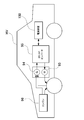
- FIG. 14 shows an example in which a power supply device is mounted on a hybrid vehicle that runs with both an engine and a motor.
- a vehicle HV equipped with the power supply device shown in this figure includes an engine 96 and a travel motor 93 that travel the vehicle HV, a power supply device 100 that supplies power to the motor 93, and a generator that charges a battery of the power supply device 100.
- the power supply apparatus 100 is connected to a motor 93 and a generator 94 via a DC / AC inverter 95.
- the vehicle HV travels by both the motor 93 and the engine 96 while charging / discharging the battery of the power supply device 100.
- the motor 93 is driven to drive the vehicle when the engine efficiency is low, for example, during acceleration or low-speed driving.
- the motor 93 is driven by power supplied from the power supply device 100.
- the generator 94 is driven by the engine 96 or is driven by regenerative braking when the vehicle is braked to charge the battery of the power supply device 100. (Power
- FIG. 15 shows an example in which a power supply device is mounted on an electric vehicle that runs only with a motor.
- a vehicle EV equipped with the power supply device shown in this figure includes a traveling motor 93 for traveling the vehicle EV, a power supply device 100 that supplies power to the motor 93, and a generator 94 that charges a battery of the power supply device 100.
- the motor 93 is driven by power supplied from the power supply device 100.
- the generator 94 is driven by energy when regeneratively braking the vehicle EV and charges the battery of the power supply device 100.
- each element constituting the present invention may be configured such that a plurality of elements are constituted by the same member and the plurality of elements are shared by one member, and conversely, the function of one member is constituted by a plurality of members. It can also be realized by sharing.
- the power supply device according to the present invention and a vehicle including the power supply device can be suitably used as a power supply device for a plug-in hybrid electric vehicle, a hybrid electric vehicle, an electric vehicle, or the like that can switch between the EV traveling mode and the HEV traveling mode.
- a backup power supply device that can be mounted on a rack of a computer server, a backup power supply device for a wireless base station such as a mobile phone, a power storage device for home use and a factory, a power supply for a street light, etc. Also, it can be used as appropriate for applications such as a backup power source such as a traffic light.
- Blower fan 58 ... Upper and lower partition walls, 93 ... Motor, 94 ... Generator, 95 ... DC / AC inverter, 96 ... Engine, 100 ... Power supply, d ... Height, ST ... Seat, HV ... Hybrid vehicle, EV ... Electric car
Landscapes
- Chemical & Material Sciences (AREA)
- Chemical Kinetics & Catalysis (AREA)
- Electrochemistry (AREA)
- General Chemical & Material Sciences (AREA)
- Engineering & Computer Science (AREA)
- Manufacturing & Machinery (AREA)
- Inorganic Chemistry (AREA)
- Microelectronics & Electronic Packaging (AREA)
- Sustainable Development (AREA)
- Sustainable Energy (AREA)
- Power Engineering (AREA)
- Transportation (AREA)
- Mechanical Engineering (AREA)
- Life Sciences & Earth Sciences (AREA)
- Aviation & Aerospace Engineering (AREA)
- Battery Mounting, Suspending (AREA)
- Secondary Cells (AREA)
- Electric Propulsion And Braking For Vehicles (AREA)
Abstract
Priority Applications (3)
| Application Number | Priority Date | Filing Date | Title |
|---|---|---|---|
| CN201580076020.XA CN107210398B (zh) | 2015-03-31 | 2015-11-06 | 电源装置以及具有该电源装置的车辆 |
| US15/540,376 US10879572B2 (en) | 2015-03-31 | 2015-11-06 | Power supply device and vehicle provided with same |
| JP2017508800A JP6400838B2 (ja) | 2015-03-31 | 2015-11-06 | 電源装置及びこれを備える車両 |
Applications Claiming Priority (2)
| Application Number | Priority Date | Filing Date | Title |
|---|---|---|---|
| JP2015-073506 | 2015-03-31 | ||
| JP2015073506 | 2015-03-31 |
Publications (1)
| Publication Number | Publication Date |
|---|---|
| WO2016157263A1 true WO2016157263A1 (fr) | 2016-10-06 |
Family
ID=57006749
Family Applications (1)
| Application Number | Title | Priority Date | Filing Date |
|---|---|---|---|
| PCT/JP2015/005566 Ceased WO2016157263A1 (fr) | 2015-03-31 | 2015-11-06 | Dispositif d'alimentation et dispositif électronique équipé d'un tel dispositif |
Country Status (4)
| Country | Link |
|---|---|
| US (1) | US10879572B2 (fr) |
| JP (1) | JP6400838B2 (fr) |
| CN (1) | CN107210398B (fr) |
| WO (1) | WO2016157263A1 (fr) |
Cited By (6)
| Publication number | Priority date | Publication date | Assignee | Title |
|---|---|---|---|---|
| JP2019016565A (ja) * | 2017-07-10 | 2019-01-31 | トヨタ自動車株式会社 | 電源装置の製造方法 |
| JPWO2021111850A1 (fr) * | 2019-12-06 | 2021-06-10 | ||
| JP2021150110A (ja) * | 2020-03-18 | 2021-09-27 | 株式会社Subaru | 電池スタック構造 |
| US20220223939A1 (en) * | 2020-04-29 | 2022-07-14 | Lg Energy Solution, Ltd. | Battery Module And Battery Pack Including The Same |
| JP2024145766A (ja) * | 2023-03-31 | 2024-10-15 | ダイハツ工業株式会社 | 電動車 |
| US12183903B2 (en) | 2019-05-14 | 2024-12-31 | Kabushiki Kaisha Toshiba | Storage battery device |
Families Citing this family (14)
| Publication number | Priority date | Publication date | Assignee | Title |
|---|---|---|---|---|
| KR102580847B1 (ko) * | 2018-04-26 | 2023-09-19 | 에스케이온 주식회사 | 배터리 랙 |
| CN109920949B (zh) * | 2019-02-18 | 2021-10-22 | 上海汽车集团股份有限公司 | 轻量化动力电池箱体 |
| US12355053B2 (en) | 2019-03-05 | 2025-07-08 | Ge Grid Solutions Llc | Systems and methods for cooling power electronics in an energy storage system |
| KR102846582B1 (ko) * | 2019-09-30 | 2025-08-13 | 에스케이온 주식회사 | 배터리 모듈 |
| DE102019133496B3 (de) * | 2019-12-09 | 2020-12-17 | Dr. Ing. H.C. F. Porsche Aktiengesellschaft | Teilkarosserie für ein wenigstens teilweise elektrisch betriebenes Kraftfahrzeug und Kraftfahrzeug |
| CN111525210B (zh) * | 2020-04-27 | 2021-12-28 | 深圳市元鼎科技有限公司 | 户外电源 |
| JP7443185B2 (ja) * | 2020-07-29 | 2024-03-05 | 本田技研工業株式会社 | 電源装置 |
| JP7167103B2 (ja) | 2020-08-25 | 2022-11-08 | プライムプラネットエナジー&ソリューションズ株式会社 | 蓄電装置およびその製造方法 |
| CN112510312A (zh) * | 2020-11-09 | 2021-03-16 | 东风汽车集团有限公司 | 一种电动车的动力电池箱 |
| WO2022197867A1 (fr) * | 2021-03-17 | 2022-09-22 | Power.Global, Pbc | Module de batterie pour véhicule ou kiosque |
| CN117042994B (zh) * | 2021-04-05 | 2024-06-18 | 日产自动车株式会社 | 高电压电子单元车载构造 |
| KR102669127B1 (ko) | 2021-12-02 | 2024-05-23 | 엘지전자 주식회사 | 에너지저장장치 |
| CN115566346A (zh) * | 2022-09-01 | 2023-01-03 | 风帆有限责任公司 | 车载集成电池系统 |
| EP4510308A3 (fr) * | 2023-08-10 | 2025-03-19 | Hyundai Motor Company | Bloc-batterie de véhicule |
Citations (5)
| Publication number | Priority date | Publication date | Assignee | Title |
|---|---|---|---|---|
| JPH05193366A (ja) * | 1992-01-22 | 1993-08-03 | Honda Motor Co Ltd | 電気自動車用バッテリの固定構造 |
| JP2011146289A (ja) * | 2010-01-15 | 2011-07-28 | Mitsubishi Motors Corp | 車両用バッテリケース |
| JP2012054054A (ja) * | 2010-08-31 | 2012-03-15 | Toyota Motor Corp | 蓄電装置および車両 |
| JP2013109845A (ja) * | 2011-11-17 | 2013-06-06 | Mitsubishi Motors Corp | 電動車のバッテリーパック構造 |
| JP2014072087A (ja) * | 2012-09-28 | 2014-04-21 | Lithium Energy Japan:Kk | 蓄電装置 |
Family Cites Families (11)
| Publication number | Priority date | Publication date | Assignee | Title |
|---|---|---|---|---|
| US5392873A (en) * | 1992-01-22 | 1995-02-28 | Honda Giken Kogyo Kabushiki Kaisha | Structure for securing batteries used in an electric vehicle |
| JP4543464B2 (ja) * | 1999-12-09 | 2010-09-15 | トヨタ自動車株式会社 | 電池パック |
| JP4294372B2 (ja) * | 2003-05-21 | 2009-07-08 | 本田技研工業株式会社 | 高圧電装部品の車載構造 |
| EP2067194B8 (fr) * | 2006-09-25 | 2018-07-18 | Lg Chem, Ltd. | Cartouche de module de cellule et module de batterie de taille moyenne comportant une telle cartouche |
| JP4919102B2 (ja) | 2008-11-17 | 2012-04-18 | 本田技研工業株式会社 | 車両用電源ユニットの冷却構造 |
| JP2011049014A (ja) * | 2009-08-26 | 2011-03-10 | Sanyo Electric Co Ltd | 防水構造のバッテリパック |
| EP2525426B1 (fr) | 2010-01-15 | 2017-10-18 | Mitsubishi Jidosha Kogyo Kabushiki Kaisha | Bac d'accumulateur pour véhicule |
| JP2011181415A (ja) * | 2010-03-02 | 2011-09-15 | Sanyo Electric Co Ltd | 安定化回路を備えるバッテリパック |
| JP5902078B2 (ja) * | 2012-11-08 | 2016-04-13 | 本田技研工業株式会社 | 電動車両 |
| JP5910692B2 (ja) | 2014-09-29 | 2016-04-27 | 三菱自動車工業株式会社 | 電動車のバッテリーパック構造 |
| US9825343B2 (en) * | 2014-09-30 | 2017-11-21 | Johnson Controls Technology Company | Battery module passive thermal management features and positioning |
-
2015
- 2015-11-06 WO PCT/JP2015/005566 patent/WO2016157263A1/fr not_active Ceased
- 2015-11-06 US US15/540,376 patent/US10879572B2/en active Active
- 2015-11-06 CN CN201580076020.XA patent/CN107210398B/zh active Active
- 2015-11-06 JP JP2017508800A patent/JP6400838B2/ja active Active
Patent Citations (5)
| Publication number | Priority date | Publication date | Assignee | Title |
|---|---|---|---|---|
| JPH05193366A (ja) * | 1992-01-22 | 1993-08-03 | Honda Motor Co Ltd | 電気自動車用バッテリの固定構造 |
| JP2011146289A (ja) * | 2010-01-15 | 2011-07-28 | Mitsubishi Motors Corp | 車両用バッテリケース |
| JP2012054054A (ja) * | 2010-08-31 | 2012-03-15 | Toyota Motor Corp | 蓄電装置および車両 |
| JP2013109845A (ja) * | 2011-11-17 | 2013-06-06 | Mitsubishi Motors Corp | 電動車のバッテリーパック構造 |
| JP2014072087A (ja) * | 2012-09-28 | 2014-04-21 | Lithium Energy Japan:Kk | 蓄電装置 |
Cited By (9)
| Publication number | Priority date | Publication date | Assignee | Title |
|---|---|---|---|---|
| JP2019016565A (ja) * | 2017-07-10 | 2019-01-31 | トヨタ自動車株式会社 | 電源装置の製造方法 |
| US12183903B2 (en) | 2019-05-14 | 2024-12-31 | Kabushiki Kaisha Toshiba | Storage battery device |
| JPWO2021111850A1 (fr) * | 2019-12-06 | 2021-06-10 | ||
| JP7248151B2 (ja) | 2019-12-06 | 2023-03-29 | 三菱自動車工業株式会社 | 車両用電池パック |
| JP2021150110A (ja) * | 2020-03-18 | 2021-09-27 | 株式会社Subaru | 電池スタック構造 |
| JP7505901B2 (ja) | 2020-03-18 | 2024-06-25 | 株式会社Subaru | 電池スタック構造 |
| US20220223939A1 (en) * | 2020-04-29 | 2022-07-14 | Lg Energy Solution, Ltd. | Battery Module And Battery Pack Including The Same |
| JP2024145766A (ja) * | 2023-03-31 | 2024-10-15 | ダイハツ工業株式会社 | 電動車 |
| JP7720345B2 (ja) | 2023-03-31 | 2025-08-07 | ダイハツ工業株式会社 | 電動車 |
Also Published As
| Publication number | Publication date |
|---|---|
| CN107210398A (zh) | 2017-09-26 |
| US20170365897A1 (en) | 2017-12-21 |
| CN107210398B (zh) | 2021-05-25 |
| JP6400838B2 (ja) | 2018-10-03 |
| US10879572B2 (en) | 2020-12-29 |
| JPWO2016157263A1 (ja) | 2017-09-14 |
Similar Documents
| Publication | Publication Date | Title |
|---|---|---|
| JP6400838B2 (ja) | 電源装置及びこれを備える車両 | |
| JP7051862B2 (ja) | バッテリシステム及びこのバッテリシステムを備える車両 | |
| JP6189301B2 (ja) | 電源装置及びこれを備える電動車両並びに蓄電装置 | |
| JP6490105B2 (ja) | グリッピング部が備えられているカートリッジを含んでいる電池モジュール | |
| JP6138688B2 (ja) | 電源装置及びこれを備える車両並びに蓄電装置 | |
| JP5528772B2 (ja) | 電源装置及びこれを備える車両並びに防水ケース | |
| CN112514145A (zh) | 车辆用的电池系统和搭载该电池系统的车辆 | |
| JP2013229182A (ja) | 電源装置、電源装置を備える車両及び蓄電装置 | |
| US20120141855A1 (en) | Battery pack for suppressing deviation of central battery cell and vehicle including the same | |
| WO2013161655A1 (fr) | Dispositif d'alimentation électrique, véhicule comprenant celui-ci, et dispositif de stockage d'électricité | |
| CN105658459B (zh) | 燃料电池车辆及燃料电池组的车载方法 | |
| JPWO2012057322A1 (ja) | 組電池及びこれを用いた車両 | |
| WO2014024451A1 (fr) | Dispositif d'alimentation électrique, et véhicule électrique ainsi que dispositif d'accumulation électrique équipés de celui-ci | |
| WO2013031614A1 (fr) | Dispositif d'alimentation électrique ainsi que véhicule équipé de celui-ci, et dispositif de stockage | |
| JP2014500587A (ja) | バッテリーモジュールケース | |
| CN103718374A (zh) | 具有外部热管理系统的电池系统 | |
| WO2014024450A1 (fr) | Dispositif d'alimentation électrique, et véhicule électrique ainsi que dispositif d'accumulation électrique équipés de celui-ci | |
| US20150303420A1 (en) | Temperature regulation structure | |
| JP6759007B2 (ja) | 電源装置及びこれを備える車両 | |
| CN111133607A (zh) | 电源装置 | |
| JP2015187912A (ja) | 電源装置の製造方法、電源装置及びこれを備える電動車両並びに蓄電装置 | |
| JP5119727B2 (ja) | ラミネート電池パックの冷却装置 | |
| KR20170065832A (ko) | 3층 적층 구조의 전지팩용 베이스 플레이트 | |
| JP2011159482A (ja) | 電源装置及びこれを備える車両 | |
| KR20200093258A (ko) | 전기 자동차용 배터리 충전 장치 |
Legal Events
| Date | Code | Title | Description |
|---|---|---|---|
| 121 | Ep: the epo has been informed by wipo that ep was designated in this application |
Ref document number: 15887420 Country of ref document: EP Kind code of ref document: A1 |
|
| ENP | Entry into the national phase |
Ref document number: 2017508800 Country of ref document: JP Kind code of ref document: A |
|
| WWE | Wipo information: entry into national phase |
Ref document number: 15540376 Country of ref document: US |
|
| NENP | Non-entry into the national phase |
Ref country code: DE |
|
| 122 | Ep: pct application non-entry in european phase |
Ref document number: 15887420 Country of ref document: EP Kind code of ref document: A1 |