WO2016157355A1 - パイプレンチ - Google Patents
パイプレンチ Download PDFInfo
- Publication number
- WO2016157355A1 WO2016157355A1 PCT/JP2015/059891 JP2015059891W WO2016157355A1 WO 2016157355 A1 WO2016157355 A1 WO 2016157355A1 JP 2015059891 W JP2015059891 W JP 2015059891W WO 2016157355 A1 WO2016157355 A1 WO 2016157355A1
- Authority
- WO
- WIPO (PCT)
- Prior art keywords
- frame
- upper jaw
- main body
- pipe wrench
- worm
- Prior art date
- Legal status (The legal status is an assumption and is not a legal conclusion. Google has not performed a legal analysis and makes no representation as to the accuracy of the status listed.)
- Ceased
Links
Images




Classifications
-
- B—PERFORMING OPERATIONS; TRANSPORTING
- B25—HAND TOOLS; PORTABLE POWER-DRIVEN TOOLS; MANIPULATORS
- B25B—TOOLS OR BENCH DEVICES NOT OTHERWISE PROVIDED FOR, FOR FASTENING, CONNECTING, DISENGAGING, OR HOLDING
- B25B13/00—Spanners; Wrenches
- B25B13/48—Spanners; Wrenches for special purposes
- B25B13/50—Spanners; Wrenches for special purposes for operating on work of special profile, e.g. pipes
Definitions
- the present invention relates to a pipe wrench suitable for piping work such as a water pipe and a gas pipe.
- the present applicant has developed a thin corner wrench shown in Patent Document 1.
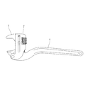
- this corner wrench as shown in FIG. 2, the frame 3 that supports the upper jaw 5 so as to be movable protrudes in a direction perpendicular to the longitudinal direction of the main body 4, so that it is parallel to the wall or another pipe.
- the frame 3 hits obstacles around it, and tightening work may not be possible.
- the object of the present invention is to solve the above-mentioned conventional problems, and even when it is necessary to use two pipe wrench at a narrow interval, mutual interference can be avoided, and a corner wrench-shaped pipe wrench is used. It is to provide a new pipe wrench that can be used even in places where it cannot.
- the pipe wrench of the present invention which has been made to solve the above-mentioned problems, includes an elongated body having a tooth implant at the tip, a frame pivotally supported by a rivet on the side of the tip of the body, and an upper jaw passing through the frame And a worm for moving the upper jaw in the longitudinal direction of the main body, and the worm is supported by the frame at a position between the main body and the upper jaw.
- the frame is formed by bending a steel plate into a U shape, and the worm can be supported by the corner portion and the upper jaw formed in the window hole. Further, the worm can have a structure in which protrusions are provided at both ends, and these protrusions are inserted between U-shaped steel plates. Further, the end of the frame opposite to the rivet can be protruded obliquely so as to be in contact with an inclined surface formed on the main body.
- a worm is disposed at a position between the elongated main body and the upper jaw, the worm is meshed with a rack formed on the side surface of the upper jaw on the main body side, and the worm is rotated to rotate the upper jaw to the main body.
- the structure is moved in the longitudinal direction. For this reason, the conventional round nut having a large outer diameter can be eliminated, and the horizontal width of the pipe wrench can be reduced. Therefore, even when it is necessary to use two pipe wrenches at a narrow interval, mutual interference can be avoided.
- the pipe wrench of the present invention has a structure in which an upper jaw that moves in the longitudinal direction of the main body is provided on a frame that is pivotally supported on the side of the front end of the main body. It has the same basic form as a pipe wrench. For this reason, it can be used even in a place where a corner wrench-shaped pipe wrench cannot be used, as in the case of installing a pipe parallel to a wall or another pipe.
- the shaft for supporting the worm becomes unnecessary and the shaft is supported. It is not necessary to provide a hole to be formed in the frame. For this reason, it is possible to reduce the number of parts and the processing and assembly work.
- the worm can be prevented from rattling without complicating the structure.
- the frame end opposite to the rivet that pivots the frame is protruded diagonally and is in contact with the inclined surface formed on the body, the frame rotates when tightening pipes and joints.
- the force can be received on a plane closer to the right angle with respect to the direction of rotation of the frame end. For this reason, even if there is a processing error of the frame, the inclination of the frame at the time of tightening can be maintained almost constant.
- FIG. 9 is a cross-sectional view taken along the line AA in FIG. It is a B arrow view of FIG. It is a front view which shows the state which opened the upper jaw.
- FIG. 4 is a front view of the pipe wrench of the embodiment.
- reference numeral 10 denotes a main body provided with an elongated handle portion 11, and a tooth implant 12 is fixed to the tip thereof.
- the tooth implant 12 is attached so that its tooth surface 13 is substantially perpendicular to the longitudinal direction of the main body 10.
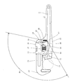
- the main body 10 includes a through hole 14 at a position slightly rearward of the tooth implant 12 at the tip, and a rivet 15 passing through the through hole 14 causes a frame to be formed on the side of the tip of the main body 10. 16 is pivotally supported. As shown in FIGS. 8 and 9, the frame 16 is formed by bending a steel plate into a U shape, and the front end side thereof is pivotally supported by the main body 10.
- a window hole 17 is formed in the frame 16, and a worm 18 is supported therein.
- the worm 18 has a spiral blade 20 protruding from the outer peripheral surface of the cylindrical portion 19. Further, small-diameter columnar projections 21 and 21 are formed at both ends of the columnar portion 19.
- the window hole 17 includes corner portions 22 that receive the cylindrical portion 19 on the front, rear, left, and right sides of the worm 18. Since the frame 16 is formed by bending a steel plate into a U-shape, the corner portions 22 are at four locations, front, rear, left, and right, and the column portion 19 of the worm 18 is supported.
- small-diameter columnar projections 21 and 21 at both ends of the worm 18 are sandwiched between U-shaped bent portions as shown in FIG. 18 rattles are prevented.
- the rack portion 24 of the upper jaw 23 passes through the bent portion of the frame 16, and the rack portion 24 and the worm 18 are engaged with each other. That is, the worm 18 is supported so as to be sandwiched between the corner portion 22 that receives the cylindrical portion 19 provided in the frame 16 and the rack portion 24 of the upper jaw 23 at a position between the main body 10 and the upper jaw 23. By rotating, the upper jaw 23 can be moved in the longitudinal direction of the main body 10.
- the shaft for supporting the worm 18 is not necessary, and it is not necessary to provide a hole for supporting the shaft in the frame. For this reason, the number of parts can be reduced. Further, it is only necessary to drop the worm 18 into the window hole 17 of the frame 16. In addition, since a conventional round nut with a large outer diameter is not used, the overall width of the pipe wrench can be reduced as shown in FIG. 5, and it is necessary to use two pipe wrench at a narrow interval. Mutual interference can be avoided.
- two protrusions 25 are formed at the center of the main body 10, and the rack portion 24 of the upper jaw 23 is sandwiched between these protrusions 25 and 25.
- a compression coil spring 26 is provided inside the protrusions 25, 25, and the rack portion 24 of the upper jaw 23 is always repelled in a direction away from the main body 10. For this reason, as in the prior art, the upper jaw 23 receives a force in a direction approaching the tooth implant 12.
- the pipe wrench constructed in this manner opens the upper jaw 23 as shown in FIG. 11 and bites an elbow, nipple, or the like between the tooth implant 12 and applies a force in the direction of the arrow to the handle portion 11 of the main body 10. In addition, it is rotated. Since this structure is close to the general pipe wrench shown in Fig. 3, use it even when a corner wrench-shaped pipe wrench cannot be used, for example, when installing a pipe parallel to a wall or another pipe. Can do.
- the end portion 27 of the frame 16 is brought into contact with the inclined surface 28 formed on the main body 10 so that the rotational force applied to the frame 16 and the force received by the contact surface are reduced.
- the formed angle ⁇ B is increased. Accordingly, there is an advantage that the variation in the angle of the frame 16 due to the variation in the processing dimension can be suppressed to the minimum without greatly extending the end portion of the frame 16 downward.
- the pipe wrench of the present invention is thin and can avoid mutual interference even when it is necessary to use two with a narrow interval, even in a place where a corner wrench shaped pipe wrench cannot be used. There are advantages that can be used.
Landscapes
- Engineering & Computer Science (AREA)
- Mechanical Engineering (AREA)
- Clamps And Clips (AREA)
- Gripping Jigs, Holding Jigs, And Positioning Jigs (AREA)
Abstract
本発明のパイプレンチは、狭い間隔で2本のパイプレンチを使用する必要がある場合にも相互の干渉を避けることができ、コーナーレンチを使用できない場所でも使用することができるものであり、先端に植歯(12)を備えた細長い本体(10)と、本体(10)の先端部側方にリベット(15)により軸支されたフレーム(16)と、フレーム(16)を貫通する上顎(23)と、上顎(23)を本体(10)の長手方向に移動させるウォーム(18)とからなるパイプレンチである。本発明のパイプレンチはウォーム(18)を本体(10)と上顎(23)との間の位置でフレーム(16)に支持させた構造とすることにより、薄型化を可能とした。
Description
本発明は、水道管やガス管等の配管作業に適したパイプレンチに関するものである。
水道管やガス管等を接続する場合には、図1に示すようにエルボ1やニップル2等の継手が用いられる。このような場合に、ニップルのねじ部を疵付けないように締め付けるためには、図1に示されるように幅の狭い部分に2本のパイプレンチを差し込んで互いに逆方向に回転させる作業が必要となる。
このため本出願人は、特許文献1に示される薄型のコーナーレンチを開発した。しかしこのコーナーレンチは図2に示すように、上顎5を移動可能に支持するフレーム3が本体4の長手方向に対して直角方向に大きく突出しているため、壁や別の配管に対して平行に配管を設置する場合には、フレーム3がまわりの障害物に当たり、締付作業が行えない場合があった。
このような場合には、特許文献2に示されるフレームの突出量が小さい一般的なパイプレンチを用いることが考えられる。しかし一般的なパイプレンチは図3に示すように、外径の大きい丸ナット6の内部に上顎5のラック部7を挿入し、丸ナット6を回転させて上顎5を本体4の長手方向に移動させる構造となっている。このため、パイプレンチの幅を丸ナット6の直径より薄くすることはできず、幅の狭い部分で2つのパイプレンチを使用すると、互いが干渉することがあった。
従って本発明の目的は上記した従来の問題点を解決し、狭い間隔で2本のパイプレンチを使用する必要がある場合にも相互の干渉を避けることができ、コーナーレンチ形状のパイプレンチを使用できない場所でも使用することができる新規なパイプレンチを提供することである。
上記の課題を解決するためになされた本発明のパイプレンチは、先端に植歯を備えた細長い本体と、本体の先端部側方にリベットにより軸支されたフレームと、このフレームを貫通する上顎と、この上顎を本体の長手方向に移動させるウォームとからなり、このウォームを本体と上顎との間の位置でフレームに支持させたことを特徴とするものである。
好ましい実施形態においては、フレームが鋼板をU字状に折り曲げたものであり、その窓穴に形成された角部と上顎とによってウォームを支持させた構造とすることができる。また、ウォームがその両端部に突起を備え、これらの突起をU字状に折り曲げた鋼板間に挿入した構造とすることができる。さらに、フレームの前記リベットとは反対側の端部を斜めに突出させ、本体に形成した傾斜面と当接させた構造とすることができる。
本発明のパイプレンチは、細長い本体と上顎との間の位置にウォームを配置し、このウォームを上顎の本体側の側面に形成されたラックと噛みあわせ、ウォームを回転させることによって上顎を本体の長手方向に移動させる構造とした。このため従来のような外径の大きい丸ナットを無くすことができ、パイプレンチの横幅を薄くすることができた。従って、狭い間隔で2本のパイプレンチを使用する必要がある場合にも相互の干渉を避けることができる。
また本発明のパイプレンチは、本体の先端部側方に軸支されたフレームに本体の長手方向に移動する上顎を設けた構造であり、特許文献1に示すコーナーレンチ形状ではなく、一般的なパイプレンチと同様の基本形態を備えている。このため、壁や別の配管に対して平行に配管を設置する場合のように、コーナーレンチ形状のパイプレンチを使用できない場所でも使用することができる。
鋼板をU字状に折り曲げてフレームを構成し、その窓穴に形成された角部と上顎とによってウォームを支持させた構造とすれば、ウォームを支持させるための軸が不要となり、軸を支持する穴をフレームへ設けることも不要となる。このため部品点数の削減と、加工・組立の手数を省略することができる。
また、ウォームの両端部に突起を形成し、これらの突起をU字状に折り曲げた鋼板間に挿入した構造とすれば、構造を複雑化することなく、ウォームのガタツキを防止することができる。
さらにフレームを本体に枢着するリベットとは反対側のフレーム端部を斜めに突出させ、本体に形成した傾斜面と当接させた構造とすれば、パイプや継手の締付時のフレームの回転力をフレーム端部の回転方向に対してより直角に近い面で受けることができる。このためフレームの加工誤差等があっても、締付け時のフレームの傾きをほぼ一定に維持することができる。
図4~図11を参照しつつ、本発明の実施形態を説明する。
図4は実施形態のパイプレンチの正面図である。図中、10は細長いハンドル部11を備えた本体であり、その先端には植歯12が固定されている。植歯12はその歯面13が本体10の長手方向に対してほぼ直角となるように取付けられている。
図4は実施形態のパイプレンチの正面図である。図中、10は細長いハンドル部11を備えた本体であり、その先端には植歯12が固定されている。植歯12はその歯面13が本体10の長手方向に対してほぼ直角となるように取付けられている。
本体10は図4、図7に示すように先端部の植歯12よりもやや後方位置に貫通孔14を備え、この貫通孔14を貫通するリベット15によって、本体10の先端部側方にフレーム16が軸支されている。フレーム16は図8、図9に示すように鋼板をU字状に折り曲げたものであり、その先端側が本体10に軸支されている。
フレーム16には窓穴17が形成されており、その内部にウォーム18が支持されている。ウォーム18は円柱部19の外周面に螺旋羽根20を突出させたものである。またこの円柱部19の両端部には、小径円柱状の突起21、21が形成されている。図8に示すように、窓穴17はウォーム18の前後左右に円柱部19を受ける角部22を備えている。フレーム16は鋼板をU字状に折り曲げたものであるから、角部22は前後左右の4か所となり、ウォーム18の円柱部19が支持される。
また、ウォーム18の両端部の小径円柱状の突起21、21が、図10のB矢視図に示すようにU字状の折り曲げ部に挟み込まれることにより、矢印方向の移動が防止され、ウォーム18のガタツキが防止される。
図4、図6に示すように、上顎23のラック部24がフレーム16の折り曲げ部を貫通しており、ラック部24とウォーム18とが噛み合っている。すなわち、ウォーム18は本体10と上顎23との間の位置でフレーム16に備えられた円柱部19を受ける角部22と上顎23のラック部24に挟み込まれるように支持されており、ウォーム18を回転させることによって、上顎23を本体10の長手方向に移動させることができる。
このような構造としたので、ウォーム18を支持する軸は不要となり、軸を支持する穴をフレームへ設けることも不要となる。このため部品点数の削減を図ることができる。またウォーム18をフレーム16の窓穴17内に落とし込むだけでよい。また従来のような外径の大きい丸ナットを用いないので、図5に示すようにパイプレンチの全幅を小さくすることができ、狭い間隔で2本のパイプレンチを使用する必要がある場合にも相互の干渉を避けることができる。
図6に示すように、本体10の中央部には2枚の突起25が形成されており、上顎23のラック部24がこれらの突起25,25の間に挟み込まれるようになっている。そしてこの突起25,25の内側には、圧縮コイルばね26が設けられており、上顎23のラック部24を常に本体10から離れる方向に弾発している。このため従来と同様、上顎23は植歯12に接近する方向の力を受けている。
このように構成されたパイプレンチは、図11に示すように上顎23を開き、エルボやニップル等を植歯12との間に噛み込ませて、本体10のハンドル部11に矢印方向の力を加えて回転させるものである。この構造は図3に示した一般的なパイプレンチに近いので、コーナーレンチ形状のパイプレンチが使用できない場合、例えば壁や別の配管に対して平行に配管を設置するような場合でも使用することができる。
図4において本体10のハンドル部11に矢印方向の力を加えて回転させる時、上顎23と植歯12の歯面13の摩擦力により、フレーム16はリベット15を回転中心として斜めに突出させた端部27が本体10の傾斜面28に当接する。
図3に示した従来構造では、本体4に矢印方向の力を加えた時、フレーム3が本体4と当接する面は垂直面8となっており、フレーム3にかかる回転力と垂直面8で受ける力のなす角度はθAとなる。θAが直角に近いほど当接する面の加工寸法のバラつきによりフレーム3の角度がバラつきやすい。このため図3の従来品はフレーム3の端部を大きく下方に延ばしてθAを大きくしている。
これに対して本実施形態においては、図4に示すようにフレーム16の端部27を本体10に形成した傾斜面28と当接させ、フレーム16にかかる回転力と当接面で受ける力のなす角度θBを大きくしている。これによりフレーム16の端部を大きく下方に延ばすことなく、加工寸法のバラつきによるフレーム16の角度のバラつきを最小限に抑制することができる利点がある。
以上に説明したように、本発明のパイプレンチは薄型であり、狭い間隔で2本使用する必要がある場合にも相互の干渉を避けることができ、コーナーレンチ形状のパイプレンチを使用できない場所でも使用することができる利点がある。
1 エルボ
2 ニップル
3 フレーム
4 本体(従来技術)
5 上顎
6 丸ナット
7 ラック
8 垂直面
10 本体(実施形態)
11 ハンドル部
12 植歯
13 歯面
14 貫通孔
15 リベット
16 フレーム
17 窓穴
18 ウォーム
19 円柱部
20 螺旋羽根
21 突起
22 角部
23 上顎
24 ラック部
25 突起
26 圧縮コイルばね
27 端部
28 傾斜面
2 ニップル
3 フレーム
4 本体(従来技術)
5 上顎
6 丸ナット
7 ラック
8 垂直面
10 本体(実施形態)
11 ハンドル部
12 植歯
13 歯面
14 貫通孔
15 リベット
16 フレーム
17 窓穴
18 ウォーム
19 円柱部
20 螺旋羽根
21 突起
22 角部
23 上顎
24 ラック部
25 突起
26 圧縮コイルばね
27 端部
28 傾斜面
Claims (4)
- 先端に植歯を備えた細長い本体と、本体の先端部側方にリベットにより軸支されたフレームと、このフレームを貫通する上顎と、この上顎を本体の長手方向に移動させるウォームとからなり、このウォームを本体と上顎との間の位置でフレームに支持させたことを特徴とするパイプレンチ。
- フレームが、鋼板をU字状に折り曲げたものであり、その窓穴に形成された角部と上顎とによってウォームを支持させたことを特徴とする請求項1記載のパイプレンチ。
- ウォームがその両端部に突起を備え、これらの突起をU字状に折り曲げた鋼板間に挿入したことを特徴とする請求項2記載のパイプレンチ。
- フレームの前記リベットとは反対側の端部を斜めに突出させ、本体に形成した傾斜面と当接させたことを特徴とする請求項1記載のパイプレンチ。
Priority Applications (2)
| Application Number | Priority Date | Filing Date | Title |
|---|---|---|---|
| JP2017508880A JP6632609B2 (ja) | 2015-03-30 | 2015-03-30 | パイプレンチ |
| PCT/JP2015/059891 WO2016157355A1 (ja) | 2015-03-30 | 2015-03-30 | パイプレンチ |
Applications Claiming Priority (1)
| Application Number | Priority Date | Filing Date | Title |
|---|---|---|---|
| PCT/JP2015/059891 WO2016157355A1 (ja) | 2015-03-30 | 2015-03-30 | パイプレンチ |
Publications (1)
| Publication Number | Publication Date |
|---|---|
| WO2016157355A1 true WO2016157355A1 (ja) | 2016-10-06 |
Family
ID=57003980
Family Applications (1)
| Application Number | Title | Priority Date | Filing Date |
|---|---|---|---|
| PCT/JP2015/059891 Ceased WO2016157355A1 (ja) | 2015-03-30 | 2015-03-30 | パイプレンチ |
Country Status (2)
| Country | Link |
|---|---|
| JP (1) | JP6632609B2 (ja) |
| WO (1) | WO2016157355A1 (ja) |
Citations (5)
| Publication number | Priority date | Publication date | Assignee | Title |
|---|---|---|---|---|
| US1526749A (en) * | 1924-04-08 | 1925-02-17 | Fred Larson | Wrench |
| US2991677A (en) * | 1959-03-16 | 1961-07-11 | Savarin & Veuve Foinant Sa | Slidably adjustable inner jaw wrench |
| JPS5415396U (ja) * | 1977-07-04 | 1979-01-31 | ||
| JPS6310070U (ja) * | 1986-07-04 | 1988-01-22 | ||
| JPH0819966A (ja) * | 1994-07-01 | 1996-01-23 | Mitsuya Shiba | パイプレンチ |
Family Cites Families (1)
| Publication number | Priority date | Publication date | Assignee | Title |
|---|---|---|---|---|
| JP5539701B2 (ja) * | 2009-11-24 | 2014-07-02 | 株式会社スーパーツール | レンチ |
-
2015
- 2015-03-30 WO PCT/JP2015/059891 patent/WO2016157355A1/ja not_active Ceased
- 2015-03-30 JP JP2017508880A patent/JP6632609B2/ja active Active
Patent Citations (5)
| Publication number | Priority date | Publication date | Assignee | Title |
|---|---|---|---|---|
| US1526749A (en) * | 1924-04-08 | 1925-02-17 | Fred Larson | Wrench |
| US2991677A (en) * | 1959-03-16 | 1961-07-11 | Savarin & Veuve Foinant Sa | Slidably adjustable inner jaw wrench |
| JPS5415396U (ja) * | 1977-07-04 | 1979-01-31 | ||
| JPS6310070U (ja) * | 1986-07-04 | 1988-01-22 | ||
| JPH0819966A (ja) * | 1994-07-01 | 1996-01-23 | Mitsuya Shiba | パイプレンチ |
Also Published As
| Publication number | Publication date |
|---|---|
| JPWO2016157355A1 (ja) | 2018-01-25 |
| JP6632609B2 (ja) | 2020-01-22 |
Similar Documents
| Publication | Publication Date | Title |
|---|---|---|
| TWI735941B (zh) | 六角起子 | |
| JP7100384B2 (ja) | ラチェットレンチのトグル部材構造 | |
| TWI671168B (zh) | 壓接鉗 | |
| US9662698B2 (en) | Tube bender | |
| CN105605174B (zh) | 棘轮机构弹簧 | |
| TW201032957A (en) | Driving component structure of dual size driving tool | |
| JP2006341338A (ja) | 加工用クランプ | |
| WO2016157355A1 (ja) | パイプレンチ | |
| CN203853900U (zh) | 自锁大力钳 | |
| CN111601669A (zh) | 折叠钳 | |
| TWI566892B (zh) | 液壓式球接頭拆卸器 | |
| TW201527050A (zh) | 具有強固結構之活動扳手 | |
| CN104080578B (zh) | 开口扳手头 | |
| CN203936842U (zh) | 扳手 | |
| TWM474598U (zh) | 具有強固裝置的活動扳手 | |
| TWI644763B (zh) | 越夾越緊的鉗子 | |
| JP6304802B2 (ja) | 蝶番矯正具及び蝶番矯正方法 | |
| JP5916182B1 (ja) | 控え金具 | |
| CN106500908B (zh) | 角度可修正扭矩杠杆装置 | |
| JP6360689B2 (ja) | スパナ | |
| RU2623377C2 (ru) | Разводной гаечный ключ | |
| JP2007038273A (ja) | 段付け加工治具 | |
| JPH0746465Y2 (ja) | 単能型トルクレンチ | |
| US20180185991A1 (en) | Dual head ratchet and socket wrench assembly | |
| CN212192131U (zh) | 一种板状物固定装置 |
Legal Events
| Date | Code | Title | Description |
|---|---|---|---|
| 121 | Ep: the epo has been informed by wipo that ep was designated in this application |
Ref document number: 15887508 Country of ref document: EP Kind code of ref document: A1 |
|
| ENP | Entry into the national phase |
Ref document number: 2017508880 Country of ref document: JP Kind code of ref document: A |
|
| NENP | Non-entry into the national phase |
Ref country code: DE |
|
| 122 | Ep: pct application non-entry in european phase |
Ref document number: 15887508 Country of ref document: EP Kind code of ref document: A1 |