WO2016157392A1 - 部品情報管理システム及び部品情報管理方法 - Google Patents
部品情報管理システム及び部品情報管理方法 Download PDFInfo
- Publication number
- WO2016157392A1 WO2016157392A1 PCT/JP2015/060021 JP2015060021W WO2016157392A1 WO 2016157392 A1 WO2016157392 A1 WO 2016157392A1 JP 2015060021 W JP2015060021 W JP 2015060021W WO 2016157392 A1 WO2016157392 A1 WO 2016157392A1
- Authority
- WO
- WIPO (PCT)
- Prior art keywords
- information
- component
- component information
- acquired
- parts
- Prior art date
- Legal status (The legal status is an assumption and is not a legal conclusion. Google has not performed a legal analysis and makes no representation as to the accuracy of the status listed.)
- Ceased
Links
Images




Classifications
-
- G—PHYSICS
- G07—CHECKING-DEVICES
- G07C—TIME OR ATTENDANCE REGISTERS; REGISTERING OR INDICATING THE WORKING OF MACHINES; GENERATING RANDOM NUMBERS; VOTING OR LOTTERY APPARATUS; ARRANGEMENTS, SYSTEMS OR APPARATUS FOR CHECKING NOT PROVIDED FOR ELSEWHERE
- G07C5/00—Registering or indicating the working of vehicles
- G07C5/08—Registering or indicating performance data other than driving, working, idle, or waiting time, with or without registering driving, working, idle or waiting time
- G07C5/0841—Registering performance data
- G07C5/085—Registering performance data using electronic data carriers
-
- G—PHYSICS
- G06—COMPUTING OR CALCULATING; COUNTING
- G06Q—INFORMATION AND COMMUNICATION TECHNOLOGY [ICT] SPECIALLY ADAPTED FOR ADMINISTRATIVE, COMMERCIAL, FINANCIAL, MANAGERIAL OR SUPERVISORY PURPOSES; SYSTEMS OR METHODS SPECIALLY ADAPTED FOR ADMINISTRATIVE, COMMERCIAL, FINANCIAL, MANAGERIAL OR SUPERVISORY PURPOSES, NOT OTHERWISE PROVIDED FOR
- G06Q50/00—Information and communication technology [ICT] specially adapted for implementation of business processes of specific business sectors, e.g. utilities or tourism
- G06Q50/10—Services
-
- E—FIXED CONSTRUCTIONS
- E02—HYDRAULIC ENGINEERING; FOUNDATIONS; SOIL SHIFTING
- E02F—DREDGING; SOIL-SHIFTING
- E02F9/00—Component parts of dredgers or soil-shifting machines, not restricted to one of the kinds covered by groups E02F3/00 - E02F7/00
- E02F9/20—Drives; Control devices
- E02F9/2025—Particular purposes of control systems not otherwise provided for
-
- E—FIXED CONSTRUCTIONS
- E02—HYDRAULIC ENGINEERING; FOUNDATIONS; SOIL SHIFTING
- E02F—DREDGING; SOIL-SHIFTING
- E02F9/00—Component parts of dredgers or soil-shifting machines, not restricted to one of the kinds covered by groups E02F3/00 - E02F7/00
- E02F9/20—Drives; Control devices
-
- E—FIXED CONSTRUCTIONS
- E02—HYDRAULIC ENGINEERING; FOUNDATIONS; SOIL SHIFTING
- E02F—DREDGING; SOIL-SHIFTING
- E02F9/00—Component parts of dredgers or soil-shifting machines, not restricted to one of the kinds covered by groups E02F3/00 - E02F7/00
- E02F9/26—Indicating devices
-
- E—FIXED CONSTRUCTIONS
- E02—HYDRAULIC ENGINEERING; FOUNDATIONS; SOIL SHIFTING
- E02F—DREDGING; SOIL-SHIFTING
- E02F9/00—Component parts of dredgers or soil-shifting machines, not restricted to one of the kinds covered by groups E02F3/00 - E02F7/00
- E02F9/26—Indicating devices
- E02F9/264—Sensors and their calibration for indicating the position of the work tool
- E02F9/265—Sensors and their calibration for indicating the position of the work tool with follow-up actions (e.g. control signals sent to actuate the work tool)
-
- E—FIXED CONSTRUCTIONS
- E02—HYDRAULIC ENGINEERING; FOUNDATIONS; SOIL SHIFTING
- E02F—DREDGING; SOIL-SHIFTING
- E02F9/00—Component parts of dredgers or soil-shifting machines, not restricted to one of the kinds covered by groups E02F3/00 - E02F7/00
- E02F9/26—Indicating devices
- E02F9/267—Diagnosing or detecting failure of vehicles
- E02F9/268—Diagnosing or detecting failure of vehicles with failure correction follow-up actions
-
- G—PHYSICS
- G06—COMPUTING OR CALCULATING; COUNTING
- G06K—GRAPHICAL DATA READING; PRESENTATION OF DATA; RECORD CARRIERS; HANDLING RECORD CARRIERS
- G06K17/00—Methods or arrangements for effecting co-operative working between equipments covered by two or more of main groups G06K1/00 - G06K15/00, e.g. automatic card files incorporating conveying and reading operations
-
- G—PHYSICS
- G07—CHECKING-DEVICES
- G07C—TIME OR ATTENDANCE REGISTERS; REGISTERING OR INDICATING THE WORKING OF MACHINES; GENERATING RANDOM NUMBERS; VOTING OR LOTTERY APPARATUS; ARRANGEMENTS, SYSTEMS OR APPARATUS FOR CHECKING NOT PROVIDED FOR ELSEWHERE
- G07C5/00—Registering or indicating the working of vehicles
- G07C5/08—Registering or indicating performance data other than driving, working, idle, or waiting time, with or without registering driving, working, idle or waiting time
- G07C5/0816—Indicating performance data, e.g. occurrence of a malfunction
-
- E—FIXED CONSTRUCTIONS
- E02—HYDRAULIC ENGINEERING; FOUNDATIONS; SOIL SHIFTING
- E02F—DREDGING; SOIL-SHIFTING
- E02F3/00—Dredgers; Soil-shifting machines
- E02F3/04—Dredgers; Soil-shifting machines mechanically-driven
- E02F3/28—Dredgers; Soil-shifting machines mechanically-driven with digging tools mounted on a dipper- or bucket-arm, i.e. there is either one arm or a pair of arms, e.g. dippers, buckets
- E02F3/30—Dredgers; Soil-shifting machines mechanically-driven with digging tools mounted on a dipper- or bucket-arm, i.e. there is either one arm or a pair of arms, e.g. dippers, buckets with a dipper-arm pivoted on a cantilever beam, i.e. boom
- E02F3/32—Dredgers; Soil-shifting machines mechanically-driven with digging tools mounted on a dipper- or bucket-arm, i.e. there is either one arm or a pair of arms, e.g. dippers, buckets with a dipper-arm pivoted on a cantilever beam, i.e. boom working downwardly and towards the machine, e.g. with backhoes
Definitions
- the present invention relates to a parts information management system and a parts information management method, for example, a parts information management system and a parts information management method for managing parts information of parts provided in a work vehicle.
- the controller issues an engine stoppage or a warning by monitoring.
- the controller stores the filter installation time and calculates the next replacement time to notify the operator. Further, the controller stores the presence / absence of replacement of the genuine filter and the number of replacements.
- spare parts (unused parts) and used parts may be stored (arranged) or left in the work vehicle.
- a replacement part currently in use a replacement part installed at a predetermined installation position
- a replacement part of the same type as the replacement part are disposed within the communication range of the reader, Since the reader obtains information from each replacement part, there is a possibility that it is difficult to know which replacement part is the replacement part currently used. In such a case, there is a risk that management of replacement parts or collection management of unnecessary parts cannot be performed properly.
- the present invention has an object to provide a parts information management system and a parts information management method that can notify the possibility that parts are left unattended.
- the component information management system is an identification device that is attached to a mounted component that is installed at a preset installation position and stores component information for identifying the mounted component; Managing a communication device that wirelessly communicates with an identification device to acquire the component information, a transmission device that transmits acquisition information including the component information acquired by the communication device, and the acquisition information received from the transmission device
- the component information includes type information indicating a type of the mounted part and unique information for distinguishing each mounted part in the same type of mounted part.
- the management device includes the same type of component information, which is the component information having the same type information but different specific information, in the received information to be installed at the installation position.
- the acquired information determining means for determining whether or not the number of attached parts is greater than the number of parts, and the acquired information determining means includes the same type of part information more than the number of parts in the acquired information. And determining means for notifying abnormality information.
- the part number and name of the attached part can be exemplified, and as the unique information, information unique to the attached part (for example, serial number) or information unique to the identification device (for example, tag ID) Can be illustrated.
- the information which shows that the to-be-attached components which are not installed in the said installation position may exist, for example can be mentioned.
- examples of the notification method by the notification means include displaying the content of the abnormality information on a monitor and outputting the content of the abnormality information to a speaker.
- the component information is acquired from each identification device by the communication device.
- the identification device attached to the attached part (attached part in use) installed at the installation position and the same type as the attached part, but at a position different from the installation position
- component information may be acquired from each identification device by the communication device.
- These pieces of component information are pieces of component information (identical type component information) having the same type information but different unique information.
- the acquisition information including such component information is transmitted to the management device via the transmission device.
- the acquisition information determination unit determines whether or not the received acquisition information includes more of the same type component information than the corresponding number of components.
- the number of parts of the same type included in the acquired information is 2 and the number of parts is 2, the number of parts of the same type matches the number of corresponding mounted parts. Therefore, the number of parts of the same type is normal.
- the attached part indicated by any one of the parts of the same type is arranged (leaved) at a position different from the installation position. May have been.
- the abnormality information is notified by the notification means.
- the management device includes a storage unit that stores the type information and the number of components in association with each other, and the acquisition information determination unit includes the storage unit from the storage unit.
- the number of parts of the attached part corresponding to the type information included in the same type part information is acquired, and it is determined whether the acquired information includes the same type part information more than the number of parts. It is preferable.
- the number of parts to be attached (number of parts) installed at the installation position is stored in the storage unit, so that the acquisition information determination unit includes the same type component included in the acquired acquisition information. Whether or not the number of pieces of information is larger than the number of parts can be easily and appropriately determined. Therefore, it is possible to appropriately determine whether there is a mounted part that is not installed at the installation position.
- the communication device includes a measurement unit that measures the reception intensity of the radio wave that is output from the identification device and received by the communication device, including the component information.
- the transmission device transmits the acquisition information in which the reception intensity measured by the measurement unit and the component information included in the radio wave are associated with each other to the management device, and the management device If the acquisition information determination unit determines that the acquisition information includes more parts of the same type than the number of parts, the reception strength associated with the parts of the same type and the information of the same type.
- the same type component information whose difference with the received intensity acquired in the past for the mounted component indicated by the type information Has a specifying means for specifying as the component information of the object to be attached parts that are not installed in position, the notification means, together with the abnormality information, it is preferable to notify the component information specified by the specifying means.
- the relative distance of the identification device to the communication device can be grasped based on the reception intensity of the radio wave received from the identification device.
- the installation position is There is a possibility that the mounted parts exist at different positions.
- the measurement unit of the communication device measures the reception intensity of the radio wave received from the identification device, and the transmission device receives the component information included in the received radio wave and the reception intensity of the radio wave.
- the specifying unit determines that a difference between the reception intensity associated with the same type component information and the reception intensity acquired in the past for the attached part indicated by the type information included in the same type component information is within a predetermined range.
- the same type component information that is outside is specified as the component information of the mounted component that is not installed at the installation position.
- the component information management system is an identification device that is attached to a mounted component that is installed at a preset installation position and stores component information for identifying the mounted component;
- a communication device that wirelessly communicates with an identification device to acquire the component information;
- a transmission device that transmits the component information acquired by the communication device;
- a management device that manages the component information received from the transmission device;
- the component information includes type information indicating a type of the attached component, and the communication device includes the component information and is output from the identification device and received by the communication device.
- Measuring means for measuring intensity wherein the transmitting device transmits the received intensity measured by the measuring unit and the component information included in the radio wave to the management device;
- the physical device associates the acquired component information with the reception intensity, and the reception acquired in the past for the attached component indicated by the acquired reception intensity and the type information included in the acquired component information.
- State determination means for determining whether or not the state in which the difference from the intensity exceeds the predetermined range has continued for a predetermined period; and the state in which the state in which the difference exceeds the predetermined range has continued for a predetermined period
- a notification means for notifying abnormality information when the determination means makes a determination.
- the notification means As a notification method by the notification means, a notification method similar to the notification means of the component information management system according to the first aspect can be exemplified.
- a counterfeit product a mounted part to which an identification device is not attached or a mounted part to which an inappropriate identification device is attached
- a genuine product the above-described identification
- a mounted part to which the device is attached is arranged.
- the genuine product is erroneously recognized as being installed at the installation position by acquiring the part information from the identification device attached to the genuine product.
- the reception intensity of the radio wave output from the identification device fluctuates depending on the distance between the identification device and the communication device as described above, and also temporarily varies depending on environmental factors.
- the change in the received intensity is an index indicating whether or not the mounted part is removed from the installation position (an index indicating whether or not the mounted member is disposed at a position different from the installation position)
- the environmental factor If the reception intensity varies due to the above, there is a possibility that it is determined that the attached part has been removed. In this case, the actual use state and the use state grasped by the management device are deviated.
- fluctuations in reception intensity due to environmental factors are temporary, if the state in which the reception intensity changes continues for a long time, it can be determined that the attached part has been removed from the installation position without any problem.
- the received strength related to the newly acquired component information and the mounted component indicated by the type information included in the component information in the past by the state determination unit of the management device When it is determined that the state in which the difference from the acquired reception intensity is outside the predetermined range has continued for a predetermined period, the notification unit notifies the abnormality information. According to this, it is possible to notify the manager of the management apparatus and the like of the possibility that the attached part installed at the installation position is removed and left in the vicinity of the installation position. Therefore, it is possible to appropriately manage the mounted parts.
- a work vehicle including the identification device, the communication device, and the transmission device, a management center having the management device, the work vehicle, and the management center. And a communication network for wirelessly connecting the two.
- the part information of the mounted parts installed in the work vehicle can be managed by the management center located away from the work vehicle via the communication network.
- a parts information management system includes a work vehicle, a management center, and a communication network that connects the work vehicle and the management center wirelessly, and the work vehicle is set in advance.
- An identification device that is attached to a filter installed at an installation position and stores component information for identifying the filter, a communication device that wirelessly communicates with the identification device to acquire the component information, and the communication device
- a transmission device that transmits the acquired information including the acquired component information, and the management center includes a management device that manages the acquired information received from the transmission device, and the component information is stored in the filter.
- Storage means for associating and storing the type information and the number of parts that is the number of the filters installed at the installation position, and the same type parts that are the part information having the same type information but different specific information
- the number of parts corresponding to the type information included in the information is acquired from the storage unit, and it is determined whether or not the acquired information includes the same type part information more than the acquired number of parts.
- the component information management method is a component information management method for acquiring and managing component information, wherein the component information is a type of a mounted component that is installed at a preset installation position. And the same type that is the part information having the same type information but different pieces of the specific information, and the specific information for distinguishing the attached parts in the attached parts of the same type. It is determined whether or not the component information has been acquired more than the number of components, which is the number of the mounted components installed at the installation position, and it is determined that the same type of component information more than the number of components has been acquired. And anomaly information is reported.
- the part information management method is implemented using a system (particularly a management device) having the same configuration as the part information management system according to the first aspect. The same effects as the parts information management system can be obtained.
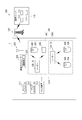
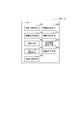
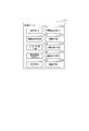
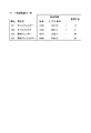
- FIG. 1 is a perspective view showing a hydraulic excavator that is a work vehicle according to an embodiment of the present invention. Schematic which shows a machine room. Schematic which shows the inside of a pump room. Schematic which shows the structure of an IC tag. The figure explaining component information. 1 is a block diagram showing a configuration of a hydraulic excavator and a schematic configuration of a component information management system. The block diagram which shows the structure of a leader (master). The block diagram which shows the structure of a leader (slave). The block diagram which shows the structure of a management server. The figure which shows an example of server acquisition information. The flowchart which shows components information management processing.
- FIG. 1 is a perspective view showing a hydraulic excavator 1 as an example of a work vehicle of the present invention.
- the parts information management system 100 communicates parts and engines EG mounted on a work vehicle at a management center 110 (see FIG. 6) at a position different from that of the work vehicle. Management and monitoring via the network 120.
- the component information management system 100 includes a management center 110, at least one work vehicle (for example, the excavator 1 shown in FIG. 1), a communication network 120 that transmits and receives information between the management center 110 and the work vehicle, Is provided.
- the target work vehicle may be, for example, different types of work vehicles such as a hydraulic excavator and a bulldozer.
- the communication network 120 is a network for data communication by wireless communication, and a mobile phone network or a satellite communication network can be used.
- the parts information management system 100 including the hydraulic excavator 1 as a work vehicle is illustrated, but the present invention can also be applied to a construction machine as another work vehicle.
- the excavator 1 includes a vehicle body 2 and a work implement 3 as shown in FIG.
- the vehicle body 2 includes a traveling device 4 and an upper swing body 5.
- the side on which the work implement 3 and the operator cab 5B are arranged is the front
- the side on which the machine room 5A is arranged is the rear.
- the left side toward the front is the left of the upper swing body 5, and the right side toward the front is the right of the upper swing body 5.
- the excavator 1 and the vehicle main body 2 are on the lower side of the traveling device 4 with respect to the upper swing body 5, and the upper side of the upper swing body 5 with respect to the traveling device 4.
- the lower side is the vertical direction, that is, the gravity direction side
- the upper side is the opposite side of the vertical direction.
- the hydraulic excavator 1 uses, for example, an internal combustion engine such as a diesel engine as a power generation device, but the hydraulic excavator 1 is not limited to such a configuration.
- the hydraulic excavator 1 may be, for example, a so-called hybrid power generator that combines an internal combustion engine, a generator motor, and a power storage device, or a power generator that replaces the internal combustion engine with an electric motor. Good.
- FIG. 2 is a schematic view showing the machine room 5A.
- the upper swing body 5 includes a machine room 5A, a driver's cab 5B, and a counterweight 5C.
- the machine room 5 ⁇ / b> A is disposed on one end side (rear side) of the upper swing body 5.
- the interior of the machine room 5A is partitioned into a pump room 5A1 and an engine room 5A2 by a partition wall 5A3.
- the pump room 5A1 is on the right side and the engine room 5A2 is on the left side. To position.
- the engine room 5A2 houses a cooling unit CU including a cooling core CC such as a radiator in addition to an engine EG serving as a power generation device.
- the cooling unit CU is disposed adjacent to the engine EG, and cools cooling water flowing through the engine EG, hydraulic oil flowing through hydraulic equipment (not shown), and the like.
- the engine EG is surrounded on all sides by a counterweight 5C, a partition on the front side of the engine room 5A2, the partition 5A3, and a left door (not shown), and includes a top including an engine hood disposed above the engine EG. It arrange
- a filter 20C and an identification device 30C that are fuel main filters, an identification device 30D attached to the engine EG, and a reader 15B that communicates with the identification devices 30C and 30D are provided. These will be described in detail later.
- the cab 5B is placed on the other end side (front side) of the upper swing body 5 as shown in FIG.
- the counterweight 5C is provided at the rearmost part of the upper swing body 5.
- the counterweight 5C is provided for weight balance with the work machine 3, and is filled with heavy objects. That is, the machine room 5A is disposed between the cab 5B and the counterweight 5C.
- the traveling device 4 has crawler belts 4a and 4b.
- the traveling device 4 is driven or rotated by the hydraulic motor (not shown) and the crawler belts 4a and 4b rotating.
- the working machine 3 is attached to the side of the cab 5B of the upper swing body 5 and includes a boom 6, an arm 7, a bucket 8, a boom cylinder 6A, an arm cylinder 7A, and a bucket cylinder 8A.
- a base end portion of the boom 6 is coupled to a front portion of the vehicle main body 2 via a boom pin 6B, and the boom 6 is operably attached.
- the base end portion of the arm 7 is coupled to the distal end portion of the boom 6 via the arm pin 7B, and the arm 7 is operably attached.
- a bucket 8 is coupled to the tip of the arm 7 via a bucket pin 8B, and the bucket 8 is operably attached.
- FIG. 3 is a view showing the inside of the pump room 5A1 in a state where a door (not shown) is opened from the right side of the upper swing body 5.
- FIG. 3 is a schematic diagram showing an arrangement state of the filter 20 (20A, 20B) and the leader 15 (15A) in the pump room 5A1.
- the pump room 5A1 includes a right door (not shown), a counterweight 5C, a partition wall on the front side of the pump room 5A1, and a top plate including an engine hood disposed on the upper side and surrounded by the partition wall 5A3. A substantially sealed space surrounded by a bottom plate (not shown).
- a hydraulic pump PN is accommodated in the pump room 5A1.
- the hydraulic pump PN is mechanically connected to the engine EG and is driven by driving the engine EG.
- the hydraulic pump PN discharges hydraulic oil to hydraulic equipment such as the boom cylinder 6A.
- the pump room 5A1 is provided with a bracket 11A on which the hydraulic pump PN is installed.
- a filter head 13A which is a filter holding component, is attached to the bracket 11A, and a hose 14A is attached to the filter head 13A.
- a filter head 13B is attached to the pump room 5A1 via a bracket 11B, and a fuel hose 14B is attached to the filter head 13B.
- a filter 20A is attached to the filter head 13A.
- the filter 20A is an oil filter for engine oil, and removes dust and the like contained in the engine oil flowing through the hose 14A.
- the filter 20A is connected to the engine EG (see FIG. 2) via the hose 14A.
- the engine oil staying in the engine EG is pumped up by the pump and sent to the filter 20A.
- the engine oil that has passed through the filter 20A is returned to the engine EG again.
- a filter 20B is attached to the filter head 13B.
- the filter 20B is a fuel prefilter and removes dust and the like contained in the fuel that has flowed to the fuel hose 14B.
- the filter 20B is not essential for the hydraulic excavator 1, and may be the hydraulic excavator 1 that does not include the filter 20B.
- the filter 20B (fuel prefilter) is connected to a fuel tank (not shown) via a hose 14B. Fuel in a fuel tank (not shown) is sent to the filter 20B. Thereafter, the fuel is sent to the filter 20C (fuel main filter), and the fuel that has passed through the filter 20C is sent to a fuel injection device (not shown). The excess fuel in the fuel injection device is returned to the fuel tank via a hose (not shown).
- the filters 20A and 20B are provided in the pump room 5A1, and the filter 20C is provided in the engine room 5A2.
- Each filter 20 (20A, 20B, 20C) is a part (replacement part) that needs to be replaced periodically because the internal filter member is clogged by use.
- the arrival of the regular replacement time is determined based on, for example, the cumulative operation time indicated by the SMR (service meter) that measures the operation time of the engine EG of the excavator 1.
- SMR service meter
- Identification devices 30A, 30B, and 30C are attached to these filters 20A, 20B, and 20C.
- the identification device 30D is attached to the engine EG. That is, the filters 20A, 20B, 20C and the engine EG correspond to attached parts to which the identification device 30 (30A, 30B, 30C, 30D) is attached.
- the type of attached component is sometimes referred to as a product number, and the type of component differs if the product number is different.
- the identification device 30 (30A, 30B, 30C, 30D) stores and provides information related to a mounted part (including a replacement part and a device such as an engine EG) to which the identification device 30 is attached.
- the identification devices 30A, 30B, and 30C can use a passive type IC tag 301 that generates electric power by electromagnetic induction by microwaves output from the reader 15 (15A, 15B), microwaves, or the like.
- each of the identification devices 30A, 30B, and 30C includes at least one IC tag 301 (see FIG. 4) that is an identification component. For this reason, each of the identification devices 30A, 30B, and 30C may include one IC tag 301 or a plurality of IC tags 301.
- the identification device 30 ⁇ / b> D includes one passive type IC tag 301.
- the IC tag 301 included in the identification device 30D may be the same as or different from the IC tag 301 included in the identification devices 30A, 30B, and 30C, and includes at least an IC chip 35 and an antenna 36 described later.
- the identification device 30 includes the passive type IC tag 301, the built-in battery can be made unnecessary, the cost can be reduced, and the malfunction due to running out of the battery can be prevented.
- FIG. 4 is a schematic diagram showing the configuration of the IC tag 301.
- the IC tag 301 is an RFID (Radio Frequency Identification) tag in which an IC chip 35 and an internal antenna 36 are enclosed with package materials 31 and 32.
- the IC tag 301 of the present embodiment can perform communication in a UHF (ultrahigh frequency) band, specifically, a band of 860 to 960 MHz as a communication frequency band.
- the communication frequency band of the RFID tag may be another band.
- the IC chip 35 is connected to the antenna 36.
- the shape and dimensions of the antenna 36 are set so that communication with the readers 15A and 15B is possible.
- the IC chip 35 and the antenna 36 are sandwiched between the package materials 31 and 32.
- FIG. 4 is a view through which the package material 31 is transmitted.
- Such an IC tag 301 is attached to the filters 20A, 20B, 20C and the engine EG using a bonding material such as a double-sided tape or an adhesive.
- FIG. 5 is a diagram for explaining the contents of the component information.
- the IC chip 35 identifies a code (TID: Tag Identifier) for identifying the IC chip 35 and components (for example, the filter 20 and the engine EG) to which the identification device 30 is mounted.
- Component information tag information
- EPC Electronic Product Code
- the EPC has a part name identification number for identifying the name of the part, a product number as type information for identifying the type of the component on which the identification device 30 is mounted, a manufacturing date, and individual parts among the parts having the same product number.
- Identification information including a serial number (manufacturing number) as unique information for identifying a component and a supplier code indicating the manufacturer of the component is stored.
- the part name identification number can identify parts such as an oil filter for engine oil, a fuel pre-filter, and a fuel main filter, for example. For example, each part is assigned an individual number. When the part is an engine EG, an individual number assigned to each engine may be used as the part name identification number. When the component is an engine EG, the number of overhauls of the engine EG is included in the identification information.
- the TID is unique information unique to each IC tag 301. Therefore, if the part number of a certain attached part and the TID of the IC tag 301 attached to the attached part can be acquired, the part number can be obtained even when a plurality of IC tags 301 are attached to the attached part. And by TID, each mounted part can be distinguished from the mounted part of the same product number.
- the identification device 30 has one IC tag 301, even if the combination of the product number and the TID is not known, if the information on the product number and the TID can be acquired from the identification device 30, the same product number can be attached.
- Each mounted part can be distinguished from each other.
- the serial number is unique information unique to each mounted part having the same product number. For this reason, each mounted part can be distinguished from the mounted part of the same product number by the product number and the serial number.
- FIG. 6 is a block diagram illustrating the configuration of the hydraulic excavator 1 and the schematic configuration of the component information management system 100 including the hydraulic excavator 1 according to the embodiment of the present invention.
- a reader 15 (15A, 15B) as a communication device that communicates with the identification devices 30A, 30B, 30C, 30D is attached to the machine room 5A.
- Each of these readers 15 reads and acquires the above-described component information (hereinafter sometimes referred to simply as “data”) including the identification information stored in the IC tags 301 of the identification devices 30A, 30B, 30C, and 30D.
- the reader 15 is described as having a reading function, but a reader / writer having a writing function in addition to the reading function may be used instead of the reader 15.
- Leader 15A is installed in pump room 5A1.
- the reader 15A communicates with identification devices 30A and 30B attached to the filters 20A and 20B and assumed to be located within the communication range of the reader 15A under the control of the communication controller 200 described later. Then, the reader 15A performs reading assuming that the component information from the identification devices 30A and 30B can be read. Furthermore, the reader 15A controls the operation of the reader 15B, which is another reader. That is, the reader 15A functions as a master, and the reader 15B functions as a slave whose operation is controlled by the master. The reader 15B performs reading on the assumption that component information can be read from the identification devices 30C and 30D.
- the communication range of the reader 15A indicates a range in which the reader 15A can receive a response signal output from the identification device 30 in response to the radio wave output from the reader 15A.
- the communication range of the reader 15B is the same.
- FIG. 7 is a block diagram showing a configuration of the reader 15A functioning as a master.
- the reader 15A includes an instruction determination unit 151, an information reception unit 152, a measurement unit 153, a slave control unit 154, a reception determination unit 155, an information holding unit 156, an information determination unit 157, and a transmission information generation unit 158.
- information transmission means 159 The instruction determination unit 151 determines whether or not instruction information for instructing acquisition of component information stored in the identification device 30 is input from the communication controller 200 described later. When it is determined that the instruction information is input by the instruction determination unit 151, the information reception unit 152 outputs a radio wave to the identification device 30 for a predetermined time and receives the radio wave output from the identification device 30.
- the measuring unit 153 measures a received signal strength indicator (RSSI) as the reception strength of the radio wave received from the identification device 30.
- RSSI received signal strength indicator
- the reception intensity measured by the measurement unit 153 is held by the information holding unit 156 described later in association with the component information included in the measured radio wave.
- Information in which the reception intensity measured by the measurement unit 153 is associated with the component information included in the measured radio wave is included in information transmitted by the information transmission unit 159 described later (see FIG. 10).
- the slave control means 154 controls the operation of the reader 15B that functions as a slave. For example, the slave control unit 154 outputs instruction information similar to the instruction information to the reader 15B. Based on the radio wave received by the information receiving unit 152, the reception determination unit 155 determines whether or not the radio wave including the component information stored in the identification device 30 has been received from the identification device 30. The reception determination unit 155 determines whether or not the component information has been received from the reader 15B within a predetermined time after the instruction information is output by the slave control unit 154, so that the reader 15B operates normally. It is determined whether or not.
- the information holding unit 156 determines that the reception determination unit 155 determines that the component information can be received from the identification device 30 according to the output radio wave from the information reception unit 152, and from the reader 15 (15B) functioning as a slave.
- the respective component information is held as master-side acquisition information.
- the information holding unit 156 includes the component information acquired from the identification devices 30A and 30B that are supposed to be acquired by the reader 15A and the components of the identification devices 30C and 30D acquired by the reader 15B.
- the slave side acquisition information including the information is held as master side acquisition information.
- the information holding unit 156 holds each acquired component information and each received intensity measured by the measuring unit 153 in association with each other. That is, the information holding unit 156 holds the component information included in the radio wave received from the identification device 30A and the reception intensity in association with each other, and also stores the component information included in the radio wave received from the identification device 30B and the reception. Keep the strength in relation. Since the reader 15B performs the same association, the slave-side acquired information includes the component information and reception intensity of the associated identification device 30C, and the component information and reception intensity of the associated identification device 30D, respectively. Is included. Then, the information holding unit 156 holds master side acquisition information including these component information and the corresponding reception intensity.
- the information determination unit 157 determines whether or not error information is included in the slave side acquisition information included in the master side acquisition information held in the information holding unit 156. In addition, the information determination unit 157 performs a duplication determination process for determining whether or not the held master-side acquisition information includes the same component information that is component information having the same content. That is, the information determination unit 157 corresponds to the same information determination unit of the present invention. In the present embodiment, the information determination unit 157 uses at least the same part information and the same part information (part information with the same EPC as identification information for specifying each mounted part) as the part information having the same product number and serial number. Is determined.
- the information determination unit 157 matches the product number read by the reader 15A or the reader 15B. If there is component information to be processed, it may be determined that the component information has the same content (component information having identification information having the same content). Even if the identification devices 30A, 30B, 30C, and 30D provided in the hydraulic excavator 1 are all different serial numbers (unique information), the information determination unit 157 sets the serial number read by the reader 15A or the reader 15B. If there is matching component information, it may be determined that the component information has the same content (component information having identification information having the same content).
- each of the identification devices 30A, 30B, and 30C has at least one IC tag 301.
- one reader 15 may receive component information from a plurality of identification devices 30A, 30B, 30C, or identification device 30D. That is, component information with different contents may be received from each IC tag 301 of the identification device 30.
- component information may be received from one identification device 30 by a plurality of readers 15 (15 ⁇ / b> A, 15 ⁇ / b> B) arranged at different positions.
- one reader 15 may receive component information from one IC tag 301 included in one identification device 30, and each of the plurality of readers 15 includes one identification device 30 included in one identification device 30.
- component information having the same identification information that is, the same component information is received from the IC tag 301. That is, depending on the communication status between the reader 15 and the identification device 30, component information may be received from the identification device 30 that is different from the identification device 30 that is assumed to be located within the communication range of the reader 15.
- the information holding unit 156 leaves one of the same component information and the other. An arrangement process (integration process) for deleting and integrating the component information having the same contents is executed. For this reason, the master-side acquisition information held by the information holding unit 156 does not include the same component information. In this embodiment, the information holding unit 156 deletes one of the component information determined to be the same component information and deletes the other, but the transmission information generating unit 158 does not delete the other. It may not be included in the generated transmission information.
- the transmission information generation unit 158 generates transmission information including the master side acquisition information held in the information holding unit 156. If the information determining unit 157 determines that the same part information is included, the transmission information generating unit 158 generates transmission information including the master side acquired information after the organizing process. If the reception determination unit 155 determines that the component information of the identification devices 30A and 30B has not been acquired, the transmission information generation unit 158 includes information indicating its own reader 15 (15A) and the reader Error information which is operation information including information indicating 15 operation states (information indicating that communication with the identification device 30 could not be performed) is generated.
- the transmission information generating unit 158 determines that the reception determining unit 155 has not received information from the reader 15B functioning as a slave within a predetermined time (that is, the reader 15B is not operating normally). Error information that is operation information including information indicating the reader 15 (15B) and information indicating the operation state of the reader 15 (information indicating that the reader 15 is not operating normally). Is generated. In addition, the transmission information generation unit 158 has determined by the information determination unit 157 that error information is included in the information received from the reader 15 (15B) functioning as a slave (that is, the slave-side acquisition information). In this case, error information to be transmitted to the communication controller 200 is generated based on the acquired error information.
- the acquired error information includes information indicating the reader 15 (15B) that is the transmission source and information indicating the operation state of the reader 15 (information indicating that communication with the identification device 30 has failed). Therefore, these pieces of information are included in the error information transmitted to the communication controller 200.
- the information transmission unit 159 transmits the transmission information or error information generated by the transmission information generation unit 158 to the communication controller 200 described later. The information transmitted by the information transmitting unit 159 corresponds to the acquired information of the present invention.
- Leader 15B is installed in engine room 5A2.
- the reader 15B is assumed to communicate with the identification device 30C attached to the filter 20C and the identification device 30D attached to the engine EG. That is, the reader 15B communicates with the identification devices 30C and 30D that are assumed to be located within the communication range of the reader 15B. Then, the reader 15B executes a process of reading the component information from the identification devices 30C and 30D under the control of the reader 15A.
- FIG. 8 is a block diagram showing a configuration of the reader 15B functioning as a slave.
- the leader 15B has a configuration in which a part of the leader 15A is omitted.
- the reader 15B includes the above-described instruction determination unit 151, information reception unit 152, measurement unit 153, reception determination unit 155, information holding unit 156, transmission information generation unit 158, and information transmission. Means 159 are included.
- the information holding unit 156 of the reader 15B includes the component information included in the radio waves received from the identification devices 30C and 30D by the information receiving unit 152 and the reception intensity measured by the measuring unit 153, which are associated with each other. Holds the acquired information on the slave side. Further, the transmission information generation unit 158 of the reader 15B generates transmission information based on the slave-side acquisition information held by the information holding unit 156, and the information transmission unit 159 serves as a reader that functions as the master. Send to 15A. Note that the transmission information generation unit 158 of the reader 15B also receives the above error when the reception determination unit 155 determines that the component information has not been acquired from the identification device 30 (30C, 30D) that is the acquisition target of the component information.
- the reader 15B does not include the slave control unit 154 and the information determination unit 157.
- the reader 15B includes the respective means 154 and 157, but the respective means 154 and 157 may be configured not to function.
- the information receiving means 152 of the reader 15 communicates with the IC tag 301 included in the identification device 30 using, for example, a 900 MHz UHF band radio wave. Since radio waves in this frequency band can communicate with the identification device 30 (30A, 30B, 30C, 30D) separated by about 1 m, they can be used in the pump room 5A1 and the engine room 5A2.
- the reader 15 as a reading device is used as a communication device.
- a reader / writer read / write device
- the reader 15 may be only one of the readers 15A, and there may be three or more including the readers 15A, 15B. May be. Since the communication state between the reader 15 and each identification device 30 is determined by the relative positional relationship, by providing a plurality of readers 15, the component information stored in the IC tag 301 can be read with higher probability.
- the excavator 1 that is a work vehicle is connected to the communication controller 200, the readers 15A and 15B, the engine controller 211, the pump controller 212, and the monitor device 213 as shown in FIG.
- the engine controller 211 controls the output of the engine EG by adjusting the fuel supply amount to the engine EG.
- the pump controller 212 controls the output of the pump PN.
- the monitor device 213 includes a display function for displaying the remaining amount of fuel, failure information of the excavator 1, and an input function for performing operation settings of the excavator 1.
- the monitor device 213 includes an SMR (service meter) that measures the operating time of the engine EG of the excavator 1.
- SMR service meter
- the SMR is displayed on the monitor device 213 and SMR information (cumulative operating time information). ) Is transmitted to the management center 110 via the communication controller 200 and the communication network 120.
- the communication controller 200 includes a communication terminal 202 connected to the antenna 201 in order to enable mutual communication with the management center 110 via a communication network 120 described later.
- the communication controller 200 functions as a controller that controls the operations of the controllers 211 and 212, the monitor device 213, and the reader 15.
- the communication controller 200 functions as a processing device that processes information acquired from the reader 15 and also functions as a transmission device that transmits the information to the management server 111 of the management center 110 via the communication network 120. That is, the communication controller 200 corresponds to the transmission device of the present invention. Therefore, the communication controller 200 includes a storage device for storing data acquired by the reader 15 and a program for executing the processing.
- the program executes, for example, a process for comparing data newly acquired by the reader 15 with data stored in the storage device.
- the communication controller 200 also includes an arithmetic device for executing such processing.
- the communication controller 200 activates the reader 15 when the operator of the excavator 1 operates a key switch (not shown) to start the engine EG.
- the key switch is operated to the accessory position, and the electronic devices such as the communication controller 200 and the reader 15 are supplied with power from a battery (not shown). That is, in order to operate the reader 15, the engine EG does not necessarily have to be started.
- the timing at which the reader 15 operates is not limited to this, and a timer function is provided in the communication controller 200 so that the communication controller 200 has a predetermined timing such as once a day or once a week. It may be set so that the reader 15 is activated at the time.
- the reader 15 may be periodically operated so that the component information can be acquired from the identification device 30.
- the communication controller 200 may be configured to operate the reader 15 in accordance with the operation instruction of the operator. That is, when the operator operates an operation button for generating a predetermined activation signal, the communication controller 200 may be configured to activate the reader 15 when receiving the activation signal.
- the communication controller 200 may be configured to operate the reader 15 in accordance with an operation instruction from an administrator of the management center 110 described later. That is, the administrator transmits a predetermined activation signal from the management center 110 to the hydraulic excavator 1 via the communication network 120, and the communication controller 200 operates the reader 15 when receiving the activation signal. May be.
- the management server 111 of the management center 110 executes a start signal generation program that generates the start signal at a predetermined cycle, and the start signal is automatically transmitted to the excavator 1. You may make it do.
- a sensor for detecting the attachment / detachment of the filters 20A, 20B, 20C (the filter head to which the filter 20C is attached is not shown) is provided in the filter heads 13A, 13B, and the reader 15 is operated according to the output of the sensors.
- You may comprise as follows.
- the communication controller 200 processes the data acquired by the reader 15 as described above. For example, the communication controller 200 compares the data with the stored data. If the communication controller 200 determines that new data has been acquired, the communication controller 200 updates the stored data with the newly acquired data. Such comparison processing may be performed by the management server 111 described later.
- the communication controller 200 transmits the data read from each identification device 30 to the management server 111 of the management center 110 via the communication network 120, the date / time data and the type of the work vehicle on which the communication controller 200 is provided. And vehicle specific information (ID, etc.) specific to the work vehicle are also transmitted. For this reason, the management server 111 can grasp which work vehicle the information is transmitted from.
- the communication controller 200 includes, for example, a clock IC (not shown), and date / time data can be acquired by the clock IC.
- the date and time data As the date and time data, the date and time when each reader 15 was activated (the date and time when the radio wave was transmitted), the date and time when each reader 15 read the data of the identification device 30, and the date and time when the data of the identification device 30 was transmitted to the management server 111 At least one of these can be illustrated. Note that data indicating date or time may be used instead of the date / time data.
- the other controller for example, pump controller 212) and the reader
- the management center 110 includes a management server 111 that centrally manages various types of information including part information acquired by each work vehicle.
- the management server 111 includes a mass storage device configured with a hard disk or the like.
- the management server 111 is configured to be able to communicate with a display device 112 configured with a display or the like, a communication device 113 capable of wireless or wired communication, and the like.
- the management server 111 manages and stores, for example, the component information received from the excavator 1 and the accumulated operating time information of the excavator 1 via the communication network 120.
- the management server 111 may be installed in a site where the work vehicle operates, or may be installed in a place far from the site where the work vehicle operates.
- the management server 111 may be accessible by the administrator of the management server 111, or may be accessible by other managers such as a person who manages the work vehicle and a person who performs maintenance and inspection of the work vehicle.
- FIG. 9 is a block diagram illustrating a configuration of the management server 111.
- the management server 111 includes a storage unit 1111 configured by the large-capacity storage device and a CPU (Central Processing Unit) executing a program stored in the storage unit 1111.
- the storage unit 1111 stores programs and data necessary for managing component information by the management server 111.
- the storage unit 1111 stores a component information management program for executing a component information management process described later.
- storage means 1111 has memorize
- the type of work vehicle indicates the type of work vehicle such as a hydraulic excavator or a bulldozer.
- the type of component indicates the type of component such as an oil filter or a fuel prefilter.
- the storage unit 1111 stores the acquired information including the part information and the reception intensity received from each work vehicle in association with the vehicle specific information of the work vehicle.
- the vehicle specific information may be a vehicle production number assigned to each work vehicle or a serial number assigned to each communication controller 200. That is, the vehicle unique information may be information that can identify the work vehicle for each work vehicle.
- the storage unit 1111 stores the TID and EPC included in the received component information in association with each other. For this reason, for example, the management server 111 collates newly acquired component information, that is, a combination of TID and EPC data read from the IC tag 301 with already stored component information (data).
- the replacement time of the filter 20 can be managed on the management server 111 side.
- the information acquisition unit 1112 receives acquisition information transmitted from the work vehicle (hereinafter also referred to as server acquisition information).
- server acquisition information since the same component information is integrated by the processing in the reader 15A, the server acquisition information does not include the same component information.
- the management server 111 for example, the information acquisition unit 1112 may execute the organization process (integration process).
- the error determination unit 1113 determines whether error information is included in the server acquisition information. If it is determined in this determination process that error information is included, the error information is notified by the notification means 1120 described later.
- the acquisition information determination unit 1114 determines the content of the server acquisition information.
- parts information having the same product number (type information of attached parts) and different serial numbers (specific information of attached parts) is defined as the same type of part information.
- the product number (type information) indicates the type of component such as an oil filter or a fuel prefilter.
- the serial number is information that is a different number even for parts of the same type, such as a part manufacturing number. Then, the acquisition information determination unit 1114 is installed in the server acquisition information at a preset installation position in the work vehicle, and the number of parts to be attached (number of parts) to which the identification device 30 is supposed to be attached. An information number determination process for determining whether or not more parts of the same type are included is executed.
- FIG. 10 is a diagram illustrating an example of server acquisition information. Specifically, in the information count determination process, the acquisition information determination unit 1114 first determines whether or not the same type component information is included in the server acquisition information. For example, in the parts A1 and A2 shown in FIG. 10, the product number that is the type information is the same, but the serial number that is the unique information is different. When the component information of each of these components A1 and A2 can be acquired from the work vehicle, the acquisition information determination unit 1114 treats the component information of the component A1 and the component information of the component A2 as the same type of component information, and the same type of component information. Is determined to be two.
- the acquisition information determination unit 1114 determines the number of components according to the product number included in the same type of component information in the corresponding work vehicle. Is acquired from the storage unit 1111. Then, the acquisition information determination unit 1114 determines whether or not the number of same-type component information matches the number of acquired components.
- the acquisition information determination unit 1114 further determines that the number of parts of the same type is the number of parts. Determine if more.
- the state in which it is determined that the number of parts of the same type is greater than the number of parts is, for example, the presence of the filter 20A installed in the filter head 13A, and the filter 20A of the same type (installed in the filter head 13A). It is assumed that there is an unfiltered filter 20A).
- the state in which the number of pieces of the same type of component information is determined to be smaller than the number of components is, for example, a filter that is a counterfeit (a component to which the identification device 30 is not attached) on the filter head 13A, or inappropriate identification.
- a state is assumed in which a filter to which the device 30 is attached is installed.
- the number of parts to be attached (number of parts) is “3”. It becomes.
- the number of parts is stored in the storage unit 1111.
- the component information of the components A1 to A4 shown in FIG. 10 is acquired from the work vehicle, the number of the same type component information is “4”.
- the part information includes more part information of the same type than the number of attached parts.
- the server acquisition information includes two pieces of the same type of component information, and more information of the same type of component information stored in the storage unit 1111 than the assumed number of components (number of oil filters) is stored in the server.
- the acquired information determination unit 1114 determines.
- the specifying unit 1115 is based on the reception intensity associated with the same type of component information. , At least one of a part installed at the corresponding installation position and a part not installed at the installation position is specified. Specifically, the specifying unit 1115 receives the received intensity (stored in association with the part information of the part number of the part treated as the same type of part information from the received intensity acquired in the past and stored in the storage unit 1111. Receive strength).
- the specifying unit 1115 installs the same type component information associated with the received intensity whose difference from the stored received intensity is within the predetermined range among the newly acquired same type component information at the corresponding installation position.
- Component information for example, the filter 20A installed in the filter head 13A.
- the specifying unit 1115 stores the same type component information associated with the reception intensity outside the predetermined range of the component not installed at the corresponding installation position (for example, the filter 20A left in the vicinity of the filter head 13A). Identified as part information.
- the specifying unit 1115 receives the reception acquired in the past by associating the associated reception strength with the component information of the same type information as the same type of component information included in the received server acquisition information.
- the same type component information close to the strength is specified as the component information of the component installed at the installation position.
- the specifying unit 1115 specifies the same type of component information associated with the reception strength having a large difference from the reception strength acquired in the past as the component information of the component installed at a position different from the installation position. Then, the specified component information is notified to the administrator by a notification unit 1120 described later. Whether or not the difference between the reception intensity associated with the newly acquired same-type component information and the stored reception intensity is within a predetermined range is executed by the state determination unit 1118 described later.
- the reception intensity of the identification device 30A of the oil filter 20A is stored as “11” in the storage unit 1111, and the predetermined range is within ⁇ 3.
- the reception strength related to the component A1 is “10”
- the reception strength related to the component A2 is “2”.
- the reception intensity related to the part A1 that is the oil filter is “10” with respect to “11” stored in the storage unit 1111. For this reason, the difference between the reception strengths is “1”, and the reception strength related to the component A1 is within the predetermined range.
- the reception intensity related to the part A2 which is also an oil filter is “2” with respect to “11” stored in the storage unit 1111. For this reason, the difference between the reception strengths is “9”, and the reception strength related to the component A2 is outside the predetermined range. Therefore, it is estimated that the part A2 (oil filter) is left in the vicinity of the filter head 13A.
- the specifying unit 1115 if each of the reception intensities associated with the same type component information is outside the predetermined range, the component information of the component installed at the corresponding installation position cannot be specified. .
- a counterfeit product or a filter to which an inappropriate identification device 30 is attached is attached at a corresponding installation position, and the number of genuine products (parts to which the identification device 30 is attached) exceeding the number of the components is installed.
- the component information of the component installed at the installation position cannot be acquired, and the reception intensity of the radio wave received from the identification device 30 attached to the genuine product is out of the predetermined range. There is a possibility. For these reasons, it is not possible to specify the component installed at the installation position.
- the specifying unit 1115 determines, based on the acquired part information, at least a part that may not be installed at the corresponding installation position (genuine product left in the vicinity of the installation position), that is, The component information of the component left in the vicinity of the installation position is specified, and the notification unit 1120 described later notifies the component information.
- the information comparison unit 1116 matches the number of the same type component information. It works when it is determined.
- the information comparison unit 1116 stores each piece of component information (newly acquired component information) included in the server acquisition information and component information (stored in association with the corresponding vehicle specific information) already stored in the storage unit 1111. It is determined whether each of the component information) matches.
- the information comparison unit 1116 determines that the component information matches when the serial number matches the component information included in the server acquisition information and the stored component information in the component information of the same product number. judge. On the other hand, if the serial numbers do not match, it is determined that the component information does not match.
- the update unit 1117 updates the component information stored in the storage unit 1111 with the newly acquired component information. At this time, the update unit 1117 also updates the reception intensity stored in association with each piece of component information. As a result, the latest component information is stored (stored) in the management server 111 in association with the reception intensity.
- the state determining unit 1118 determines the arrangement state of each component based on the reception intensity associated with each piece of component information. Specifically, the state determination unit 1118 performs the following determination.
- the state determination unit 1118 includes a difference between the reception intensity included in the server acquisition information and associated with each component information and the reception intensity stored in the storage unit 1111 and associated with the corresponding component information.
- a first determination process is performed to determine whether or not a predetermined range (within a predetermined error range).
- the said 1st determination process is good also as a process which determines whether the receiving intensity linked
- the predetermined range is temporary due to environmental factors centered on the reception intensity assumed for radio waves oscillated from the identification device 30 attached to the genuine product installed at the corresponding installation position.
- a range including various fluctuations (errors) can be exemplified. Therefore, the width of the predetermined range can be set in advance through experiments and tests.
- the state determination unit 1118 determines whether or not the period during which the state exceeding the predetermined range continues exceeds the predetermined period. A second determination process is executed.
- the counterfeit product or a mounted part (hereinafter, generically referred to as a counterfeit product) to which the improper identification device 30 is attached is installed at the corresponding installation position, and the genuine product is located near the installation position.
- placement there is a possibility that component information may be acquired from the identification device 30 attached to the genuine product. In this case, if no action is taken, there is a possibility that a genuine product is installed at the installation position.
- the reception intensity of the radio wave from the genuine product placed near the installation position is different from the reception intensity of the radio wave received from the genuine product identification device 30 installed in the past in the correct installation position.
- the reception intensity temporarily changes depending on environmental factors. For this reason, if the period in which the reception intensity of radio waves including certain component information exceeds the predetermined range exceeds the predetermined period set as a relatively long period, the imitation product etc. There is a possibility that is installed. For this reason, the state determination unit 1118 executes the second determination process in order to evoke such a possibility, and the period during which the state exceeding the predetermined range continues exceeds the predetermined period.
- the notification unit 1120 described later notifies the error information (second abnormality information).
- the period calculation unit 1119 calculates a duration exceeding the predetermined range when it is determined in the first determination process by the state determination unit 1118 that the difference in reception intensity exceeds the predetermined range. Specifically, the time period calculation means 1119, every time it is determined that the predetermined range is exceeded in the first determination process, the date and time indicated by the date and time data included in the previously acquired server acquisition information and the current time A difference period from the date and time indicated by the date and time data included in the acquired server acquisition information is added to the duration period. In addition, the period calculation unit 1119 initializes the duration period when it is determined in the first determination process by the state determination unit 1118 that the predetermined range is not exceeded. The duration calculated by the period calculation unit 1119 is performed for each part, that is, for each piece of component information corresponding to the part.
- the notifying unit 1120 notifies various information to an administrator such as an administrator of the management server 111, an administrator of the excavator 1, and a person who performs maintenance and inspection of the excavator 1. This notification may be performed to any of these managers or the like, or may be performed to a plurality of managers.
- the notification unit 1120 displays information on the display device 112 connected to the management server 111 to perform notification to the administrator or the like.
- the present invention is not limited to this, and may be configured to notify the administrator or the like by other methods. Further, various information may be notified from the management server 111 to a portable terminal held by the administrator or the like.
- the notification unit 1120 notifies the error information.
- the details of the error are not limited to these, and details of error information (first abnormality information and second abnormality information) will be described later.
- the notifying unit 1120 notifies the component information specified by the specifying unit 1115 and information (first abnormality information) indicating that there is a possibility that there is a component that is not installed at the installation position. As a result, it is possible to notify the administrator or the like what components are arranged without being installed at an appropriate installation position. Furthermore, when the state determination unit 1118 determines that the continuation period has exceeded the predetermined period, the notification unit 1120 includes component information related to the continuation period exceeding the predetermined period and the mounted part installed at the installation position. The information (second abnormality information) indicating that there is a possibility that the component has been removed and left unattended, or that a mounted part to be installed at the installation position may have been left unattended. As a result, it is possible to make an administrator or the like recognize the possibility that a counterfeit product or the like is installed at a corresponding installation position and a genuine product is left unattended.
- FIG. 11 is a flowchart showing the component information management process executed by the management server 111.
- the management server 111 executes the component information management program and executes the following component information management process. For example, the administrator or the like is notified of component information of components that may not be installed at the corresponding installation position.
- This component information management process is a process including the procedure shown in the component information management method of the present invention. Specifically, in the part information management process, as shown in FIG. 11, first, the information acquisition unit 1112 of the management server 111 receives information (server acquisition information) transmitted from a work vehicle such as the hydraulic excavator 1. And obtaining (step S1).
- the error determination unit 1113 determines whether or not error information is included in the acquired information (server acquisition information) (step S2). If it is determined in step S2 that the error information is included (step S2, YES), the notification unit 1120 notifies the error content including the error information (step S3). After step S3, the management server 111 ends the component information management process.
- step S2 determines whether the error information is not included (NO in step S2)
- the acquisition information determination unit 1114 includes component information that is handled as the same type component information in the server acquisition information. It is determined whether it is included (step S4). If it is determined in the determination process in step S4 that the same type component information is not included (step S4, NO), the management server 111 moves the process to step S9. On the other hand, if it is determined in the determination process in step S4 that the same type component information is included (step S4, YES), the acquisition information determination unit 1114 indicates that the number of the same type component information is the storage unit 1111.
- step S5 The number of parts stored in (the number of mounted parts mounted on the work vehicle acquired from the storage unit 1111 based on the vehicle identification information of the work vehicle and the type information included in the same type of part information) and It is determined whether or not they match (step S5). If it is determined in the determination process of step S5 that the number of pieces of the same type component information matches the number of parts (step S5, YES), the management server 111 moves the process to step S9.
- step S5 If it is determined in the determination process of step S5 that the number of parts of the same type does not match the number of parts (step S5, NO), the acquisition information determination unit 1114 further indicates that the number of parts of the same type is It is determined whether or not the number is greater than the number (step S6).
- step S6 When it is determined in the determination process of step S6 that the number of the same type component information newly acquired from the work vehicle is smaller than the number of components stored in the storage unit 1111 (step S6, NO).
- the management server 111 moves the process to step S3. And in the said step S3, the information to which the alerting
- step S6 determines whether the number of the same type component information is larger. If it is determined in the determination process in step S6 that the number of the same type component information is larger (step S6, YES), the specifying unit 1115 will appropriately select the information based on each reception intensity as described above. At least one of the component information of the component installed at the proper installation position and the component information of the component not installed at the installation position is specified (step S7). Thereafter, the notification unit 1120 notifies the specified component information and the first abnormality information (step S8). After step S8, the management server 111 ends the component information management process.
- step S9 the information comparison unit 1116 determines whether each piece of component information included in the server acquisition information matches the corresponding stored component information (step S9). If it is determined in the determination process in step S9 that they do not match (NO in step S9), the update unit 1117 updates the stored component information for the corresponding component with the component information determined not to match. (Step S10). At this time, as described above, the update unit 1117 also updates the reception intensity associated with each piece of component information. After step S10, the management server 111 ends the component information management process.
- step S11 determines whether or not the error range has been exceeded. If it is determined in the determination process in step S11 that the difference does not exceed the predetermined range (step S11, NO), a duration (in accordance with the reception intensity determined not to exceed the predetermined range) ( The duration calculating unit 1119 is initialized by the period calculation unit 1119 (step S12). That is, in step S12, the period calculation unit 1119 sets the corresponding duration to “0”. If it is determined in step S11 that all received strengths do not exceed the predetermined range, after step S12, the management server 111 ends the component information management process.
- step S11 determines whether the difference exceeds the predetermined range (step S11, YES)
- the duration corresponding to the reception intensity determined to exceed the predetermined range is as follows.
- the difference calculation period is added by the period calculation means 1119, and the continuation period is counted (step S13).
- the state determination unit 1118 executes the second determination process for determining whether or not there is a continuous period exceeding the predetermined period (step S14). If it is determined in the determination process of step S14 that there is no duration exceeding the predetermined period (step S14, NO), the management server 111 ends the component information management process.
- step S14 when it is determined in the determination process of step S14 that there is a continuous period exceeding the predetermined period, that is, when it is determined that the elapsed time from exceeding the predetermined range has continued for the predetermined period (step S14). YES), the notifying means 1120 notifies the corresponding part information and the second abnormality information (step S15). After step S15, the management server 111 ends the component information management process.
- a genuine filter of the same type as the filter 20A (hereinafter sometimes referred to as a neglected filter) may be left in the vicinity of the filter head 13A where the filter 20A as the oil filter is installed. is there.
- the neglected filter may be a used genuine filter or an unused genuine filter.
- the reader 15A acquires component information having the same product number but different serial numbers from the identification device 30 attached to each of the filter 20A and the neglect filter.
- the notification means 1120 notifies the information (first abnormality information) that the filter 20A is installed in the filter head 13A and that the neglected filter may be left.
- a non-genuine filter (a filter of the same type as the filter 20A, but not attached with the identification device 30 or a filter with an inappropriate identification device 30 attached) is attached to the filter head 13A.
- a plurality of used or unused filters 20A may be left in the vicinity of the filter head 13A.
- the number of pieces of the same type component information is greater than the number of components, but the component information cannot be acquired from a counterfeit product or the like.
- the filter installed in the filter head 13A is not specified, and each filter 20A left in the vicinity of the filter head 13A is specified. In such a case, information indicating that there is a possibility that the plurality of filters 20A may be left is notified. In this way, when the number of pieces of the same type of component information is larger than the corresponding number of components, at least the component information of the component determined to be left and the information indicating that the component may be left Will be notified.
- the received intensity is different from the received intensity.
- the reception intensity temporarily changes depending on environmental factors. For this reason, it may not be possible to determine that the filter 20A is disposed at a position different from the filter head 13A (an inappropriate position) simply because the reception intensity of the radio wave from the identification device 30A fluctuates.
- the change in the received intensity is not a temporary effect due to environmental factors, but is due to the filter 20A being disposed at a position different from the filter head 13A.
- information (second abnormality information) indicating that the filter 20A may be left without being installed at an appropriate installation position (for example, the filter head 13A) is notified. .
- the component information management system 100 has the following effects.
- the acquired information acquisition means 1114 includes the same type component information in the acquired server acquisition information, and the number of the same type component information is the corresponding component and is installed at the actual work vehicle installation position.
- the notification unit 1120 notifies the first abnormality information. According to this, it is possible to notify the administrator of the management server 111 of the possibility that there is a part left without being installed at the corresponding installation position.
- the number of mounted parts (number of parts) installed at a preset installation position in the work vehicle is stored in advance in the storage unit 1111 for each type of the work vehicle. For this reason, the acquisition information determination unit 1114 can easily and appropriately compare the number of the same type component information acquired from the work vehicle and the number of components corresponding to the type information included in the same type component information. Therefore, it is possible to appropriately determine whether there is a mounted part that is not installed at the installation position.
- the measuring unit 153 of the reader 15 as the communication device measures the reception intensity of the radio wave received from the identification device 30, and the communication controller 200 as the transmission device manages the acquisition information associated with the component information and the reception intensity.
- the identifying unit 1115 identifies the component information of the component not installed at the installation position based on the reception intensity included in the acquired server acquisition information and the reception intensity acquired in the past. To do.
- the notification unit 1120 when the state determination unit 1118 determines that the duration of the difference between the acquired reception intensity and the previously acquired reception intensity exceeding the predetermined range exceeds the predetermined period, the notification unit 1120 The second abnormality information is notified. According to this, the attached parts installed at the installation position may be removed and left in the vicinity of the installation position, or the unused attached parts may be left in the vicinity of the installation position. Can be recognized by an administrator or the like. Accordingly, it is possible to appropriately perform management such as replacement timing of attached parts and collection management of unnecessary attached parts.
- the component information management system 100 includes a work vehicle such as the hydraulic excavator 1, a management center 110, and a communication network 120 that connects them wirelessly. According to this, parts information such as replacement parts installed in the work vehicle can be managed by the management center 110 located away from the work vehicle via the communication network 120.
- the present invention is not limited to the above-described embodiment, and modifications, improvements, and the like within the scope that can achieve the object of the present invention are included in the present invention.
- the part information in which the product number as the type information and the serial number of the attached part (for example, the filter 20) as the unique information match each other is the same part information that is the same content information, and the type information Part information having the same part number and different serial numbers of attached parts as unique information are handled as part information of the same type.
- the present invention is not limited to this. That is, it may be determined whether or not the component information has the same content and whether or not the component information has the same type based on other information.
- unique information unique to the identification device 30 or the IC tag 301 such as the TID may be used.
- each mounted part can be distinguished from each other in the same type of mounted part.
- component information having the same product number but different TIDs may be the same type component information.
- the type information is not limited to the product number but may be a component name or the like.
- component information in which at least one of type information (product number) or unique information (serial number) matches may be determined as component information (same component information) having the same content. That is, in a single work vehicle (hydraulic excavator 1), when a plurality of components to which the identification device 30 is attached are different components, the type information is different for each identification device 30. Therefore, for example, when the readers 15A and 15B hold the identification information of the same type information, it can be determined that they have received the same component information. In addition, since the unique information is usually different for each component, when the readers 15A and 15B hold the identification information of the same unique information, it can be determined that they have received the same component information.
- the storage unit 1111 stores the number of attached parts for each work vehicle in advance in consideration of the possibility that a plurality of attached parts of the same type are installed in the work vehicle depending on the work vehicle. It was set as the structure. However, the present invention is not limited to this. That is, if the number of various attached parts is uniformly determined in advance to be a predetermined number (for example, “1”), it may not be stored in the storage unit 1111.
- the specifying unit 1115 sets the installation position of the same type of component information based on the corresponding reception intensity.
- the notification unit 1120 can notify the first abnormality information, and it is not necessary to notify the component information (specified component information) of the mounted component that is not installed at the installation position.
- the state determination unit 1118 is in a state where the difference between the reception intensity associated with each piece of component information and the reception intensity associated with the corresponding component information and acquired in the past exceeds a predetermined range.
- the notification unit 1120 reports the second abnormality information.
- the present invention is not limited to this. For example, such a notification process may not be performed, and the second abnormality information may be notified when it is determined that the difference between the reception strengths exceeds a predetermined range.
- the second abnormality information is notified when it is determined that the state where the acquired reception intensity exceeds the predetermined range, not the difference between the reception intensity, has continued for a predetermined period. It is good also as a structure.
- the identification devices 30A, 30B, and 30C have at least one IC tag 301. That is, the identification devices 30A, 30B, and 30C may have a configuration having one IC tag 301 or a configuration having a plurality of IC tags 301, like the identification device 30D.
- the number of identification devices 30 included in the work vehicle that is, the number of attached parts to which the identification devices 30 are attached can be changed as appropriate.
- the configuration of the IC tag 301 as the identification component is not limited to the above configuration, and may be other configurations as long as the IC chip 35 is provided.
- the identification devices 30A, 30B, and 30C are attached to the filters 20A, 20B, and 20C, respectively, and the identification device 30D is attached to the engine EG.
- the present invention is not limited to this. That is, the attached part to which the identification device 30 is attached may be changed or added as appropriate. If the part is a part (including an apparatus or an assembly) constituting the work vehicle, a replacement part provided to be replaceable may be used. It does not have to be a replacement part.
- the leader 15A that functions as a master is disposed in the pump room 5A1 in the machine room 5A
- the leader 15B that functions as a slave is an engine that is partitioned in the machine room 5A via the pump room 5A1 and the partition wall 5A3. It is assumed that it is arranged in the room 5A2.
- the present invention is not limited to this. That is, in the work vehicle, the part where the leader 15 is disposed is not limited to the machine room 5A, and the leader 15 may be disposed at a position where the leader 15 can communicate with the identification device 30 removed together with the replacement part.
- positioned do not need to be partitioned off by partition (for example, partition 5A3).
- the reception determination unit 155 of the reader 15A determines that the reader 15B is not operating normally when the transmission information from the reader 15B cannot be received.
- the present invention is not limited to this. That is, the operation state of the reader 15B may be determined based on another index.
- a temperature sensor may be provided in the engine room 5A2, and it may be determined that the reader 15B is not operating normally when the temperature measured by the temperature sensor is outside the allowable temperature range of the reader 15.
- the reader 15A after the reader 15A receives and acquires the component information, the instruction information is output, and the reader 15B receives and acquires the component information.
- the present invention is not limited to this. In other words, after the reader 15B functioning as a slave acquires component information, the reader 15A functioning as a master may acquire the component information.
- the hydraulic excavator 1 as a work vehicle includes the two leaders 15, and the leader 15A functions as a master and controls the leader 15B that functions as a slave.
- the number of readers 15 is not limited to two and can be changed as appropriate.
- the reader 15B may not be controlled by the other reader 15 (15A).
- only one leader 15 may be provided in the work vehicle.
- the parts from the identification device for all the attached parts can be obtained by providing only one reader 15.
- Information can be acquired.
- the reader 15 may determine whether the acquired component information includes the same component information, and if the same information is included, the reader 15 may perform an organization process (integration process). The reception intensity of the received radio wave may be acquired.
- the reader 15B does not have the information determination unit 157, and the information holding unit 156 of the reader 15B does not execute the organizing process.
- the present invention is not limited to this. That is, the reader 15B also includes the information determination unit 157.
- the information determination unit 157 determines that the same part information is included in the slave-side acquired information
- the information holding unit 156 of the reader 15B The organizing process for integrating the same component information included in the acquired information may be executed.
- the slave side acquisition including the component information acquired from the identification device 30 assumed to be located within the communication range or the identification device 30 not assumed to be located within the communication range.
- the information includes the identification device 30 in which the same component information is stored in a certain filter 20, if it is determined that the component information with the same content is acquired and included, the component information with the same content is integrated. . For this reason, when component information with the same content is acquired, the component information with the same content is integrated, and the slave-side acquired information after integration is transmitted to the reader 15A. On the other hand, if it is determined that the component information having the same content is not included, the held slave-side acquisition information is transmitted to the reader 15A.
- the information determination unit 157 included in the reader 15A as a master does not execute the duplication determination process on the received slave-side acquired information. Also good. In this case, if the communication ranges of the readers 15A and 15B do not overlap each other, the information determination unit 157 of the reader 15A determines the overlap only for the component information acquired from the identification device 30 by the reader 15A. It is good also as a structure which performs a process.
- the component information management system 100 in this modification includes an identification device 30 (30A, 30B, 30C, 30D) provided in the excavator 1, a reader 15 (15A, 15B), a communication controller 200, a management server 111, and the like. Composed.
- the reader 15B transmits the acquired component information to the reader 15A
- the reader 15A transmits the component information received from the reader 15B and the component information acquired by itself to the communication controller 200.
- the communication controller 200 determines whether or not the received component information includes the component information having the same identification information. If the communication controller 200 determines that the received component information includes the component information having the same identification information, the component information having the same identification information is integrated. 111 may be transmitted. Alternatively, when the management server 111 that has received the component information acquired by the readers 15A and 15B via the communication controller 200 determines whether or not the component information includes the component information having the same identification information. May integrate part information of the same identification information. When the reader 15A has the function of the communication controller 200, the component information may be transmitted directly from the reader 15A to the management server 111.
- the parts information management system 100 is configured to include the hydraulic excavator 1 as a work vehicle, but the present invention is not limited to this. That is, the parts information management system of the present invention is not limited to a configuration that informs an administrator or the like that the replacement parts constituting the work vehicle are left unattended. For example, it can be configured as a system for managing parts arranged in a store or facility.
- the work vehicle is not limited to the hydraulic excavator 1, and a construction machine such as a wheel loader, a bulldozer, a motor grader, and a dump truck, or an industrial vehicle such as a forklift may be employed.
- the present invention can be suitably used, for example, as a parts information management system for managing parts installed or arranged in a work vehicle.
- SYMBOLS 1 Hydraulic excavator (work vehicle), 13A, 13B ... Filter head (installation position), 15 (15A, 15B) ... Leader (communication device), 20 (20A, 20B, 20C) ... Filter (attachment parts), 30 (30A, 30B, 30C, 30D) ... identification device, 100 ... part information management system, 110 ... management center, 111 ... management server (management device), 120 ... communication network, 153 ... measuring means, 200 ... communication controller (transmission) (Device), 301 ... IC tag (identification component), 1111 ... storage means, 1114 ... acquisition information determination means, 1115 ... identification means, 1118 ... state determination means, 1120 ... notification means.
Landscapes
- Engineering & Computer Science (AREA)
- Business, Economics & Management (AREA)
- Physics & Mathematics (AREA)
- General Physics & Mathematics (AREA)
- Mining & Mineral Resources (AREA)
- Civil Engineering (AREA)
- General Engineering & Computer Science (AREA)
- Structural Engineering (AREA)
- Theoretical Computer Science (AREA)
- Tourism & Hospitality (AREA)
- Health & Medical Sciences (AREA)
- Economics (AREA)
- General Health & Medical Sciences (AREA)
- Human Resources & Organizations (AREA)
- Marketing (AREA)
- Primary Health Care (AREA)
- Strategic Management (AREA)
- General Business, Economics & Management (AREA)
- Component Parts Of Construction Machinery (AREA)
- Management, Administration, Business Operations System, And Electronic Commerce (AREA)
- Arrangements For Transmission Of Measured Signals (AREA)
Priority Applications (6)
| Application Number | Priority Date | Filing Date | Title |
|---|---|---|---|
| JP2017508909A JP6513790B2 (ja) | 2015-03-30 | 2015-03-30 | 部品情報管理システム及び部品情報管理方法 |
| CN201580078441.6A CN107533731A (zh) | 2015-03-30 | 2015-03-30 | 零件信息管理系统以及零件信息管理方法 |
| KR1020177024366A KR20170109035A (ko) | 2015-03-30 | 2015-03-30 | 부품 정보 관리 시스템 및 부품 정보 관리 방법 |
| PCT/JP2015/060021 WO2016157392A1 (ja) | 2015-03-30 | 2015-03-30 | 部品情報管理システム及び部品情報管理方法 |
| US15/555,833 US20180040174A1 (en) | 2015-03-30 | 2015-03-30 | Component Information Management System and Component Information Management Method |
| EP15887545.0A EP3279856A4 (de) | 2015-03-30 | 2015-03-30 | Komponenteninformationsverwaltungssystem und komponenteninformationsverwaltungsverfahren |
Applications Claiming Priority (1)
| Application Number | Priority Date | Filing Date | Title |
|---|---|---|---|
| PCT/JP2015/060021 WO2016157392A1 (ja) | 2015-03-30 | 2015-03-30 | 部品情報管理システム及び部品情報管理方法 |
Publications (1)
| Publication Number | Publication Date |
|---|---|
| WO2016157392A1 true WO2016157392A1 (ja) | 2016-10-06 |
Family
ID=57005319
Family Applications (1)
| Application Number | Title | Priority Date | Filing Date |
|---|---|---|---|
| PCT/JP2015/060021 Ceased WO2016157392A1 (ja) | 2015-03-30 | 2015-03-30 | 部品情報管理システム及び部品情報管理方法 |
Country Status (6)
| Country | Link |
|---|---|
| US (1) | US20180040174A1 (de) |
| EP (1) | EP3279856A4 (de) |
| JP (1) | JP6513790B2 (de) |
| KR (1) | KR20170109035A (de) |
| CN (1) | CN107533731A (de) |
| WO (1) | WO2016157392A1 (de) |
Cited By (5)
| Publication number | Priority date | Publication date | Assignee | Title |
|---|---|---|---|---|
| JP2020016129A (ja) * | 2018-07-27 | 2020-01-30 | 株式会社小松製作所 | 部品管理システム及び部品管理方法 |
| WO2020049740A1 (ja) * | 2018-09-07 | 2020-03-12 | 三菱電機株式会社 | 位置特定装置、位置特定システム、位置特定方法および位置特定プログラム |
| WO2023189630A1 (ja) * | 2022-03-31 | 2023-10-05 | 日立建機株式会社 | 作業機械及び部品管理システム |
| JP2024108168A (ja) * | 2020-08-07 | 2024-08-09 | 新明和工業株式会社 | 作業車両の故障診断システムおよびコンピュータプログラム |
| WO2025009200A1 (ja) * | 2023-07-04 | 2025-01-09 | 住友電気工業株式会社 | 判定装置、提供装置、判定方法、およびコンピュータプログラム |
Families Citing this family (8)
| Publication number | Priority date | Publication date | Assignee | Title |
|---|---|---|---|---|
| DE112018000705T5 (de) * | 2017-03-06 | 2019-11-14 | Cummins Filtration Ip, Inc. | Erkennung von echten filtern mit einem filterüberwachungssystem |
| JP6856467B2 (ja) * | 2017-07-14 | 2021-04-07 | 株式会社小松製作所 | 作業機械システムおよび制御方法 |
| CN111183260B (zh) * | 2017-10-05 | 2023-02-03 | 沃尔沃建筑设备公司 | 具有附接装置的工程机械和用于监控附接装置的附接状态的系统 |
| US11367320B2 (en) | 2019-09-24 | 2022-06-21 | Caterpillar Inc. | Systems and methods for part identification |
| KR102551833B1 (ko) * | 2020-12-21 | 2023-07-06 | 주식회사 젠트로피 | 지능형 차량 부품의 유지 보수를 위한 시스템 및 방법 |
| CN113052277A (zh) * | 2021-03-16 | 2021-06-29 | 中国广核电力股份有限公司 | 核电设备故障提示方法、装置、计算机设备和存储介质 |
| EP4502283A4 (de) * | 2022-03-31 | 2025-07-09 | Sumitomo Construction Machinery Co Ltd | Schaufelverwaltungssystem, schaufelverwaltungsverfahren und programm |
| US20260035878A1 (en) * | 2024-08-02 | 2026-02-05 | Kubota Corporation | Working vehicle and attachment usage system |
Citations (5)
| Publication number | Priority date | Publication date | Assignee | Title |
|---|---|---|---|---|
| JP2005273196A (ja) * | 2004-03-23 | 2005-10-06 | Sumitomo (Shi) Construction Machinery Manufacturing Co Ltd | 建設機械の交換部品識別装置 |
| JP2007172191A (ja) * | 2005-12-21 | 2007-07-05 | Fujitsu Ltd | 情報アクセス・システム、および非接触情報記憶装置内の情報にアクセスする方法 |
| JP2008025234A (ja) * | 2006-07-21 | 2008-02-07 | Komatsu Ltd | 作業機械の部品監視装置及び作業機械の部品監視方法 |
| JP2010215305A (ja) * | 2009-03-13 | 2010-09-30 | Mitsubishi Heavy Ind Ltd | 所在管理システム |
| JP2012027628A (ja) * | 2010-07-22 | 2012-02-09 | Shimizu Corp | 医療機器管理システム |
Family Cites Families (6)
| Publication number | Priority date | Publication date | Assignee | Title |
|---|---|---|---|---|
| US8810364B2 (en) * | 2006-07-11 | 2014-08-19 | Komatsu Ltd. | System for monitoring component of operating machine |
| US20080059339A1 (en) * | 2006-08-31 | 2008-03-06 | Gualandri J Joseph | Systems and methods for identifying attachments |
| WO2012116408A1 (en) * | 2011-03-01 | 2012-09-07 | Encore Automation Pty Ltd | Detection system |
| JP5607125B2 (ja) * | 2012-09-28 | 2014-10-15 | 株式会社小松製作所 | 作業機械の部品監視装置及び作業機械の部品監視方法 |
| KR101680131B1 (ko) * | 2013-09-19 | 2016-11-28 | 가부시키가이샤 고마쓰 세이사쿠쇼 | 통신 장치 및 이것을 구비한 작업 차량 |
| JP5669921B2 (ja) * | 2013-11-20 | 2015-02-18 | 三菱重工業株式会社 | 所在管理システム |
-
2015
- 2015-03-30 WO PCT/JP2015/060021 patent/WO2016157392A1/ja not_active Ceased
- 2015-03-30 US US15/555,833 patent/US20180040174A1/en not_active Abandoned
- 2015-03-30 JP JP2017508909A patent/JP6513790B2/ja not_active Expired - Fee Related
- 2015-03-30 KR KR1020177024366A patent/KR20170109035A/ko not_active Ceased
- 2015-03-30 CN CN201580078441.6A patent/CN107533731A/zh active Pending
- 2015-03-30 EP EP15887545.0A patent/EP3279856A4/de not_active Withdrawn
Patent Citations (5)
| Publication number | Priority date | Publication date | Assignee | Title |
|---|---|---|---|---|
| JP2005273196A (ja) * | 2004-03-23 | 2005-10-06 | Sumitomo (Shi) Construction Machinery Manufacturing Co Ltd | 建設機械の交換部品識別装置 |
| JP2007172191A (ja) * | 2005-12-21 | 2007-07-05 | Fujitsu Ltd | 情報アクセス・システム、および非接触情報記憶装置内の情報にアクセスする方法 |
| JP2008025234A (ja) * | 2006-07-21 | 2008-02-07 | Komatsu Ltd | 作業機械の部品監視装置及び作業機械の部品監視方法 |
| JP2010215305A (ja) * | 2009-03-13 | 2010-09-30 | Mitsubishi Heavy Ind Ltd | 所在管理システム |
| JP2012027628A (ja) * | 2010-07-22 | 2012-02-09 | Shimizu Corp | 医療機器管理システム |
Cited By (11)
| Publication number | Priority date | Publication date | Assignee | Title |
|---|---|---|---|---|
| JP2020016129A (ja) * | 2018-07-27 | 2020-01-30 | 株式会社小松製作所 | 部品管理システム及び部品管理方法 |
| JP7154058B2 (ja) | 2018-07-27 | 2022-10-17 | 株式会社小松製作所 | 部品管理システム及び部品管理方法 |
| WO2020049740A1 (ja) * | 2018-09-07 | 2020-03-12 | 三菱電機株式会社 | 位置特定装置、位置特定システム、位置特定方法および位置特定プログラム |
| JPWO2020049740A1 (ja) * | 2018-09-07 | 2021-02-18 | 三菱電機株式会社 | 位置特定装置、位置特定システム、位置特定方法および位置特定プログラム |
| US11681882B2 (en) | 2018-09-07 | 2023-06-20 | Mitsubishi Electric Corporation | Position specifying device, position specifying system, position specifying method, and computer readable storage medium |
| JP2024108168A (ja) * | 2020-08-07 | 2024-08-09 | 新明和工業株式会社 | 作業車両の故障診断システムおよびコンピュータプログラム |
| JP7606640B2 (ja) | 2020-08-07 | 2024-12-25 | 新明和工業株式会社 | 作業車両の故障診断システムおよびコンピュータプログラム |
| WO2023189630A1 (ja) * | 2022-03-31 | 2023-10-05 | 日立建機株式会社 | 作業機械及び部品管理システム |
| JP7365448B1 (ja) | 2022-03-31 | 2023-10-19 | 日立建機株式会社 | 作業機械及び部品管理システム |
| JP2023158227A (ja) * | 2022-03-31 | 2023-10-27 | 日立建機株式会社 | 作業機械及び部品管理システム |
| WO2025009200A1 (ja) * | 2023-07-04 | 2025-01-09 | 住友電気工業株式会社 | 判定装置、提供装置、判定方法、およびコンピュータプログラム |
Also Published As
| Publication number | Publication date |
|---|---|
| JP6513790B2 (ja) | 2019-05-15 |
| KR20170109035A (ko) | 2017-09-27 |
| EP3279856A4 (de) | 2018-12-05 |
| JPWO2016157392A1 (ja) | 2018-01-25 |
| EP3279856A1 (de) | 2018-02-07 |
| US20180040174A1 (en) | 2018-02-08 |
| CN107533731A (zh) | 2018-01-02 |
Similar Documents
| Publication | Publication Date | Title |
|---|---|---|
| JP6513790B2 (ja) | 部品情報管理システム及び部品情報管理方法 | |
| JP6357584B2 (ja) | 部品情報管理システム | |
| CN101512614B (zh) | 作业机械的部件监视系统 | |
| JP6479686B2 (ja) | 識別情報取得システム及び作業車両 | |
| US9991928B2 (en) | Communication system and work vehicle | |
| JP6453752B2 (ja) | 通信システムおよび作業車両 | |
| JP5607125B2 (ja) | 作業機械の部品監視装置及び作業機械の部品監視方法 | |
| JP6420853B2 (ja) | 識別情報取得システム及び作業車両 |
Legal Events
| Date | Code | Title | Description |
|---|---|---|---|
| 121 | Ep: the epo has been informed by wipo that ep was designated in this application |
Ref document number: 15887545 Country of ref document: EP Kind code of ref document: A1 |
|
| ENP | Entry into the national phase |
Ref document number: 2017508909 Country of ref document: JP Kind code of ref document: A |
|
| ENP | Entry into the national phase |
Ref document number: 20177024366 Country of ref document: KR Kind code of ref document: A |
|
| WWE | Wipo information: entry into national phase |
Ref document number: 15555833 Country of ref document: US |
|
| REEP | Request for entry into the european phase |
Ref document number: 2015887545 Country of ref document: EP |
|
| NENP | Non-entry into the national phase |
Ref country code: DE |