WO2016157448A1 - Compresseur intégré à un moteur - Google Patents
Compresseur intégré à un moteur Download PDFInfo
- Publication number
- WO2016157448A1 WO2016157448A1 PCT/JP2015/060243 JP2015060243W WO2016157448A1 WO 2016157448 A1 WO2016157448 A1 WO 2016157448A1 JP 2015060243 W JP2015060243 W JP 2015060243W WO 2016157448 A1 WO2016157448 A1 WO 2016157448A1
- Authority
- WO
- WIPO (PCT)
- Prior art keywords
- motor
- integrated compressor
- shaft
- compressor
- stator
- Prior art date
- Legal status (The legal status is an assumption and is not a legal conclusion. Google has not performed a legal analysis and makes no representation as to the accuracy of the status listed.)
- Ceased
Links
Images



Classifications
-
- F—MECHANICAL ENGINEERING; LIGHTING; HEATING; WEAPONS; BLASTING
- F04—POSITIVE - DISPLACEMENT MACHINES FOR LIQUIDS; PUMPS FOR LIQUIDS OR ELASTIC FLUIDS
- F04C—ROTARY-PISTON, OR OSCILLATING-PISTON, POSITIVE-DISPLACEMENT MACHINES FOR LIQUIDS; ROTARY-PISTON, OR OSCILLATING-PISTON, POSITIVE-DISPLACEMENT PUMPS
- F04C29/00—Component parts, details or accessories of pumps or pumping installations, not provided for in groups F04C18/00 - F04C28/00
-
- F—MECHANICAL ENGINEERING; LIGHTING; HEATING; WEAPONS; BLASTING
- F04—POSITIVE - DISPLACEMENT MACHINES FOR LIQUIDS; PUMPS FOR LIQUIDS OR ELASTIC FLUIDS
- F04C—ROTARY-PISTON, OR OSCILLATING-PISTON, POSITIVE-DISPLACEMENT MACHINES FOR LIQUIDS; ROTARY-PISTON, OR OSCILLATING-PISTON, POSITIVE-DISPLACEMENT PUMPS
- F04C29/00—Component parts, details or accessories of pumps or pumping installations, not provided for in groups F04C18/00 - F04C28/00
- F04C29/04—Heating; Cooling; Heat insulation
-
- H—ELECTRICITY
- H02—GENERATION; CONVERSION OR DISTRIBUTION OF ELECTRIC POWER
- H02K—DYNAMO-ELECTRIC MACHINES
- H02K9/00—Arrangements for cooling or ventilating
- H02K9/02—Arrangements for cooling or ventilating by ambient air flowing through the machine
Definitions
- the present invention relates to a motor-integrated compressor integrally including a motor and a compressor, and more particularly to a motor-integrated compressor using an axial gap motor.
- a radial gap motor for example, Patent Document 1 in which a motor rotor and a stator are concentrically arranged has been adopted.
- the radial gap motor cannot be reduced in size in the axial direction due to its structure, and it has been difficult to reduce the size.
- the adoption of an axial gap motor is being studied. Since the axial gap motor is arranged so that the motor rotor and the stator face each other in the axial direction (axial direction), the axial dimension can be reduced, and the compressor can be used more than when a radial gap motor is used. Can be downsized.
- motor cooling often depends on heat dissipation from the outer circumferential surface of the motor casing.
- An axial gap motor that expands in the radial direction and has a tendency to reduce the outer peripheral area of the motor casing in the radial direction tends to increase in temperature more easily than a conventional radial gap motor.
- the compressor is integrally configured by such an axial gap motor and the compressor main body, the temperature of the central portion sandwiched between the two heat generating elements is relatively higher than that of the other portions.
- the motor rotor is arranged between the stator and the compressor body, the temperature increase of the motor rotor may cause demagnetization, and the motor efficiency may be reduced.
- the heat of the motor rotor is transmitted to the suction side bearing and the suction chamber of the compressor body, and the temperature of the oil and the suction gas for cooling the suction side bearing is increased, so that the compression efficiency may be lowered.
- the present invention has been made in view of the above, and it is an object of the present invention to provide a motor-integrated compressor that can improve motor efficiency, compression efficiency, or both by efficiently cooling an axial gap motor.
- a motor-integrated compressor that can improve motor efficiency, compression efficiency, or both by efficiently cooling an axial gap motor.
- a motor-integrated compressor including a compressor main body and an axial gap motor that drives the compressor main body, wherein the axial gap motor includes a shaft as a rotating shaft and a motor casing that houses the shaft.
- a stator fixed to the inner surface of the motor casing and annularly arranged at a predetermined interval from the outer peripheral surface of the shaft; and a stator connected to the shaft and spaced from the stator in the axial direction of the shaft.
- the motor casing has an intake port formed on the output side of the axial gap motor and an exhaust port formed on the non-output side of the axial gap motor.
- the motor efficiency, the compression efficiency, or both of the motor-integrated compressor can be improved by efficiently cooling the axial gap motor.
- FIG. 3 is a perspective view showing the output-side motor rotor and the counter-output-side motor rotor from the side facing the stator in the motor-integrated compressor according to the first embodiment of the present invention.
- the motor integrated compressor which concerns on Example 1 of this invention, it is a perspective view which shows the other example of an output side motor rotor and a counter output side motor rotor from the opposing surface side with a stator. It is an AA cross-sectional view of the output side motor rotor shown in FIG. 3A.
- Example 1 of this invention it is a perspective view which shows the other example of the output side motor rotor from the surface opposite to a stator. It is a figure which shows the flow of the air which passes the inside of a motor, and the flow of the air which passes a compressor main body in the longitudinal cross-section of the motor integrated compressor which concerns on Example 1 of this invention. It is a figure which shows the flow of the air which passes the inside of a motor, and the flow of the air which passes a compressor main body in the longitudinal cross-section of the motor integrated compressor which concerns on the modification of Example 1 of this invention. It is a figure which shows the other example of an output side motor rotor in the motor integrated compressor which concerns on the modification of Example 1 of this invention.
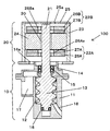
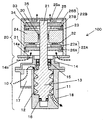
- FIG. 1 is a longitudinal sectional view of a motor-integrated compressor 100 according to Embodiment 1 of the present invention.
- the motor-integrated compressor 100 includes an oil-cooled screw air compressor (hereinafter referred to as “compressor main body”) 10 and an axial gap motor (hereinafter simply referred to as “motor”) that drives the compressor main body 10. 20 are integrally provided.
- the motor 20 will be described using a configuration in which the shaft 21 described later is disposed on the upper portion of the compressor body 10 so as to face the vertical direction, but the present invention is not limited to this, and the shaft You may comprise so that 21 may face the horizontal direction or the direction which inclines.
- the compressor body 10 includes a compressor body casing 11, a male screw rotor (hereinafter simply referred to as “screw rotor”) 13 disposed so as to mesh with the screw rotor housing chamber 12 of the compressor body casing 11, and not shown.
- a female screw rotor and a suction side bearing holding portion 14 that closes the suction side of the screw rotor housing chamber 12 are provided.
- a suction side end of the screw rotor 13 (an output side end of the shaft 21 described later) is rotatably supported by a suction side bearing 15 provided in the suction side bearing holding portion 14.
- the discharge-side end portion of the screw rotor 13 is rotatably supported by a discharge-side bearing 16 provided in the compressor body casing 11.
- a suction chamber 17 communicating with the suction side of the screw rotor housing chamber 12 is formed on the side surface portion on the suction side of the compressor body 10 by the compressor body casing 11 and the suction side bearing holding portion 14. Compressed air is guided to the suction chamber 17 through a suction communication path (not shown).
- a discharge port 18 that communicates with the discharge side of the screw rotor storage chamber 12 is formed in the side surface portion on the discharge side of the compressor body casing 11.
- the screw rotor 13 is rotationally driven by the motor 20, compresses and discharges the compression air guided to the suction chamber 17 and discharges it from the port 18.
- the motor 20 includes a shaft 21 formed integrally with the suction side of the screw rotor 13, an output side motor rotor 22 ⁇ / b> A attached to the output side of the shaft 21, and a counter output side motor rotor 22 ⁇ / b> B attached to the counter output side of the shaft 21.
- a cylindrical motor casing main body 23 that accommodates the shaft 21 and the motor rotors 22A and 22B, and a stator 24 that is fixed to the inner peripheral surface of the motor casing main body 23 and disposed between the motor rotors 22A and 22B. ing.
- the output side of the motor casing main body 23 is closed by the suction side bearing holding portion 14 of the compressor main body 10, and the opposite output side of the motor casing main body 23 is closed by the end bracket 25.
- the motor casing main body 23 constitutes a motor casing of the motor 20 together with the suction side bearing holding portion 14 and the end bracket 25.
- the output side bracket becomes unnecessary because the suction side bearing holding part 14 which is a part of the compressor body 10 closes the output side of the motor casing body 23, and is supported by the compressor body 10. Since the screw rotor 13 and the shaft 21 are integrally formed, a bearing inside the motor 20 is not necessary, and the motor 20 can be downsized. In addition, this invention is not limited to this structure, The structure which installs a bearing inside the motor 20 may be sufficient.
- the stator 24 is composed of a plurality of cores (cores) that are annularly arranged at a predetermined interval from the outer peripheral surface of the shaft 21, and a coil is wound around each of the plurality of cores. Magnetic flux is generated in the iron core by the current flowing through the coil, and a magnetic field that loops in the axial direction is formed.
- the output side motor rotor 22A has a yoke 26A connected to the shaft 21 and a plurality of magnets 27A arranged so as to face the output side end face of the stator 24 with a predetermined interval by the yoke 26A.
- the non-output-side motor rotor 22B includes a yoke 26B connected to the shaft 21 and a plurality of magnets 27B arranged so as to face the output-side end surface of the stator 24 with a predetermined interval by the yoke 26B.
- the motor rotors 22A and 22B and the shaft 21 are rotationally driven by the interaction between the magnetic fields of the magnets 27A and 27B and the magnetic field of the stator 24.
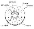
- FIG. 2 is a perspective view showing the output-side motor rotor 22A and the counter-output-side motor rotor 22B from the side facing the stator 24.
- FIG. 2 As shown in FIG. 2, since the motor rotors 22A and 22B have substantially the same configuration, the output side motor rotor 22A will be mainly described below.
- the motor rotor 22A has a disk-shaped yoke 26A and a plurality of magnets 27A.
- the plurality of magnets 27A are each magnetized in the axial direction, and are arranged on the surface of the yoke 26A facing the stator 24 so that the magnetization directions (S poles or N poles) are alternately reversed in the circumferential direction. Has been.
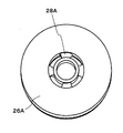
- the yoke 26A has a hole having an inner diameter larger than the outer diameter of the shaft 21 at the center, and the annular coupling member 29A is supported at the center of the hole by a plurality of support posts 28A that are spaced apart in the circumferential direction. ing.
- a plurality of through holes 26Aa penetrating in the axial direction are formed by partitioning the inner side surface of the central hole of the yoke 26A and the outer end surface of the annular coupling member 29A by a plurality of support posts 28A.
- the inner diameter of the annular connecting member 29A substantially matches the outer diameter of the shaft 21, and the output side motor rotor 22A is connected to the shaft 21 by inserting the shaft 21 into the annular connecting member 29A and fixing it.
- Each of the plurality of support columns 28A is formed in a blade shape inclined with respect to the rotation direction, and air that passes through the plurality of through holes 26Aa in the axial direction from the intake holes 14a toward the stator 24 as the motor rotor 22A rotates.
- the annular connecting member 29A and the plurality of support columns 28A are preferably formed integrally with the magnet support member 26A.
- the struts 28A and 28B formed on the yokes 26A and 26B can have various configurations as long as they generate an airflow in the axial direction as they rotate.
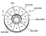
- FIG. 3A, 3B, and 3C show other examples of the column 28A and the like.
- FIG. 3A is a perspective view showing another example of the output-side motor rotor 22A and the counter-output-side motor rotor 22B from the side facing the stator 24.
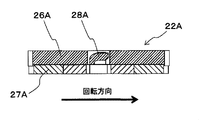
- FIG. 3B is an AA cross-sectional view of the output side motor rotor 22A shown in FIG. 3A.
- FIG. 3C is a perspective view showing another example of the output side motor rotor 22A from the side opposite to the stator 24.
- the front end in the rotation direction of the support column 28A is inclined in a streamline shape in the direction opposite to the stator 24 side (see FIG. 3B).
- the tip in the rotation direction becomes the stator 24 side and flows in the counter-rotation direction toward the back surface of the yoke 26B.
- the shape is a linear slope.
- the side of the support 28A opposite to the stator 24 has a thick shape that is parallel or horizontal to the back surface of the yoke 26A. That is, the structure is such that the strength of the support column 28A is increased by increasing the thickness of the counter-rotation direction side of the support column 28A.
- the support 28B has a thick shape in which the stator 24 side is parallel or horizontal to the radial surface of the magnet 27.
- the suction-side bearing holding portion 14 that closes the output side of the motor casing main body portion 23 penetrates in the axial direction below the output-side motor rotor 22 ⁇ / b> A, and the motor-side compressor and the interior on the output side of the motor 20.
- a plurality of air inlets 14 a communicating with the outside of 100 are provided.
- the intake port 14a is preferably formed close to the through hole 26Aa of the output side motor rotor 22A.
- the end bracket 25 that closes the non-output side of the motor casing body 23 penetrates in the axial direction above the yoke 26B of the non-output side motor rotor 22B, and the inside of the non-output side of the motor 20 and the motor-integrated compressor 100.
- the exhaust port 25a is preferably formed close to the through hole 26Ba of the counter-output side motor rotor 22B.
- FIG. 4 is a diagram showing the flow of air passing through the motor 20 and the flow of air passing through the compressor body 10 in the longitudinal section of the motor-integrated compressor 100 according to the present embodiment.
- the air inside the motor 20 is heated by the heat generated by the stator 24 (coil) and the compressor body 10 and is externally supplied from an exhaust port 25a that opens to the upper side (counter output side) of the motor 20 To be discharged.
- external air flows from the intake port 14 a that opens to the lower side (output side) of the motor 20.
- the air flowing in from the intake port 14a passes through the through hole 26Aa of the output side motor rotor 22A, the gap 30 between the shaft 21 and the stator 24, and the through hole 26Ba of the counter output side motor rotor 22B, and is discharged from the exhaust port 25a.
- the motor-integrated compressor 100 is configured so that the shaft 21 faces the vertical direction, and thus is provided on the lower side (output side) of the motor 20. Since the cooling air taken in from the intake port 14a is discharged from the exhaust port 25a provided on the upper side (opposite output side) of the motor 20 by natural convection, the motor 20 can be efficiently cooled.
- the props 28A and 28B of the motor rotors 22A and 22B can be formed in a blade shape so as to actively suck air and forcibly discharge air.
- circulates the inside of the motor 20 increases, and the cooling effect of the motor 20 improves.
- the motor-integrated compressor 100 is configured such that the shaft 21 faces the horizontal direction, air can be circulated from the output side of the motor 20 to the non-output side without depending on natural convection. This enables the motor 20 to be efficiently cooled.
- the intake-side bearing 15 is made up of the intake air 14b generated when air is sucked into the intake port 14a.
- the oil to be cooled and the air in the suction chamber 17 are cooled, and a decrease in compression efficiency is suppressed.
- a configuration in which a one-stator-to-rotor axial gap motor is used as the motor 20 is shown.
- the present invention is not limited to this.
- a one-rotor / one-stator or a three-stator / two-rotor axial gap motor is used.
- the present invention can also be applied to a configuration using.
- the blade-like support columns 28A and 28B are provided on both the output side yoke 26A and the counter output side yoke 26B. However, only one of them may be provided.
- FIG. 1 shows a configuration in which the through holes 26Aa and 26Ba are provided in the yokes 26A and 26B of the motor rotors 22A and 22B, as shown in FIG. 4, the through holes 26Aa and 26Ba are formed in the yokes 26A and 26B of the motor rotors 22A and 22B. It is also possible to adopt a configuration in which no is provided.
- the air flowing in from the intake port 14a is a gap 31 between the outer peripheral end of the output side motor rotor 22A and the inner surface of the motor casing main body 23, a gap 32 between the output side motor rotor 22A and the stator 24, a stator 24 and a shaft. 21, a gap 33 between the stator 24 and the magnet 27B, a gap 34 between the outer peripheral end of the counter-output side motor rotor 22B and the inner wall of the motor casing body 23, and a gap between the end bracket 25 and the counter-output side motor rotor 22B. It passes in order of 35 and is discharged
- the motor 20 since the cooling air taken in from the intake port 14a provided on the lower side of the motor 20 is discharged from the exhaust port 25a provided on the upper side of the motor 20 by natural convection, the motor 20 is efficiently operated. Can be cooled to. Furthermore, the centrifugal strength of the motor rotors 22A and 22B is improved by providing the motor rotors 22A and 22B with no through holes 26Aa and 26Ba.
- the yoke 26A may be provided with a blade that generates an air flow.
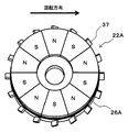
- FIG. 6 shows a configuration in which a blade is provided in the yoke 26A or the like without forming the through hole 26Aa.
- a plurality of blades 37 are arranged along the radial outer periphery of the yoke 26A.
- the blade 37 has a tip in the rotation direction inclined toward the output side, and generates an airflow that flows from the output side to the stator 24 as it rotates.
- similar blades 37 are also formed on the yoke 26B on the counter-output side.
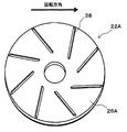
- Fig. 7 shows another example.
- a plurality of convex blades 38 extending in the axial direction are arranged on the back surface of the yoke 26A.
- the blade 38 has a linear shape in which the outer peripheral side is arranged in the counter-rotating direction and the shaft 21 side is arranged toward a position that is phased in the rotating direction. An air flow from the shaft 21 side toward the outer peripheral side is generated by the centrifugal force accompanying the rotation. Further, the tip of the blade 38 on the shaft 21 side is disposed so as to be in the vicinity of or intersecting with the axial projection surface of the intake port 14a or on the outer peripheral side thereof, and from the intake port 14a to the motor casing against the air flow generated by the blade 38. A flow of cooling air toward the outer periphery is easily generated.
- the blades 38 are not limited to a linear shape, but may have a curved shape that gradually phase toward the counter-rotating direction toward the outer peripheral side.
- FIG. 8 is a longitudinal sectional view of the motor-integrated compressor 101 according to the second embodiment of the present invention.
- the difference from the motor-integrated compressor 100 according to the first embodiment (see FIG. 1) is that the motor casing body 23 is located near the upper end in place of the plurality of exhaust ports 25 a provided in the end bracket 25.
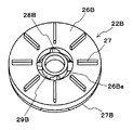
- a plurality of exhaust ports 23a penetrating in the radial direction are provided, and a plurality of protrusions 27 are provided on a surface (hereinafter referred to as “rear surface”) of the yoke 26B of the counter-output-side motor rotor 22B opposite to the stator 24. is there.
- FIG. 9 is a perspective view showing the non-output side motor rotor 22B from the back side.
- the plurality of protrusions 27 are each made of a prismatic member, and are arranged radially on the back surface of the motor rotor 22 ⁇ / b> B around the rotation axis. Note that the number, shape, arrangement, and the like of the protrusions 27 can be changed as appropriate.
- FIG. 10 is a diagram showing the flow of air passing through the motor and the flow of air passing through the compressor body 10 in the longitudinal section of the motor-integrated compressor according to the present embodiment.
- the air that has passed through the through hole 26Ba of the yoke 26B flows in the outer diameter direction by the protrusion 27 that rotates together with the counter-output side motor rotor 22B, and is discharged from the exhaust port 23a.
- the same effect as the motor-integrated compressor 100 according to the first embodiment can be obtained, and the exhaust port 23a is opened in the side surface portion of the motor 20. Intrusion of droplets or dust into the motor 20 can be suppressed.
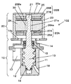
- FIG. 11 is a longitudinal sectional view of the motor-integrated compressor 102 according to the third embodiment of the present invention.
- the difference from the motor-integrated compressor 100 (see FIG. 1) according to the first embodiment is that the diameter of the portion of the shaft 21 surrounded by the stator 24 is smaller than the diameter of the other portions.
- a stepped portion 21 a is formed on the outer peripheral surface of the shaft 21.
- the same effect as the motor-integrated compressor 100 according to the first embodiment can be obtained, and the gap 30 between the shaft 21 and the stator 24 can be increased.
- the air flowing in from the output side of the motor 20 can be efficiently sent out to the non-output side, and the cooling performance of the motor 20 is further improved.
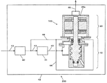
- FIG. 12 is a schematic configuration diagram of a compressor unit 200 according to Embodiment 4 of the present invention.
- the compressor unit 200 includes a motor-integrated compressor 100 (see FIG. 1) according to the first embodiment, a suction filter 40, a suction throttle valve 41, and a unit case 42.
- the suction filter 40 is provided in the suction communication passage 43 that guides the compressed air from the outside of the unit case 42 to the suction chamber 17, and removes dust contained in the compressed air sucked from the outside of the unit case 42.
- the suction throttle valve 41 is provided on the downstream side of the suction filter 40 in the suction communication passage 43, and adjusts the flow rate of the compression air that flows into the suction chamber 17.
- a part of the compressed air that has passed through the suction filter 40 is guided to the intake port 14a of the motor-integrated compressor 100 via the intake communication passage 44 branched from the suction filter 40 downstream side of the suction communication passage 43.
- the air discharged from the exhaust port 25 a of the motor-integrated compressor 100 is guided to the outside of the unit case 42 via the exhaust communication path 45.
- the same effect as that of the motor-integrated compressor 100 according to the first embodiment can be obtained, and a part of the compressed air that has passed through the suction filter 40 can be supplied to the intake port 14a. By guiding, dust can be prevented from entering the motor 20.
- the compressor unit 200 according to the present embodiment is configured to include the motor-integrated compressor 100 according to the first embodiment, but may be configured to include the motor-integrated compressor according to other embodiments.
- the compressor unit 200 has a configuration in which a part of the compressed air that has passed through the suction filter 40 is guided to the intake port 14a as motor cooling air.
- the motor cooling air is used as the compressed air. May be independently taken into the unit case 42 and passed through a suction filter provided separately from the suction filter 40 and guided to the intake port 14a.
- this invention is not limited to the above-mentioned Example, Various modifications are included.
- the above-described embodiments have been described in detail for easy understanding of the present invention, and are not necessarily limited to those having all the configurations described.
- a part of the configuration of one embodiment can be replaced with the configuration of another embodiment, or the configuration of another embodiment can be added to the configuration of one embodiment.
Landscapes
- Engineering & Computer Science (AREA)
- Mechanical Engineering (AREA)
- General Engineering & Computer Science (AREA)
- Power Engineering (AREA)
- Motor Or Generator Cooling System (AREA)
- Applications Or Details Of Rotary Compressors (AREA)
- Compressor (AREA)
- Connection Of Motors, Electrical Generators, Mechanical Devices, And The Like (AREA)
Abstract
La présente invention concerne un compresseur intégré à un moteur capable d'améliorer le rendement du moteur et l'efficacité de compression grâce à un refroidissement efficace d'un moteur à entrefer axial. Le compresseur intégré à un moteur (100) est doté d'un corps de compresseur (10) et d'un moteur à entrefer axial (20) pour entraîner le corps de compresseur. Le moteur à entrefer axial est doté d'un arbre (21) qui sert d'arbre rotatif, d'un carter de moteur (14, 23, 25) pour abriter l'arbre, d'un stator (24) qui est fixé à la surface intérieure du carter de moteur et est disposé de manière annulaire avec un espace prédéterminé par rapport à la périphérie externe de l'arbre, et de rotors de moteur (22A, 22B) qui sont connectés à l'arbre et disposés respectivement avec un espace prédéterminé par rapport au stator dans la direction axiale de l'arbre. Le carter de moteur a un orifice d'admission (14a) qui est formé sur le côté de sortie du moteur à entrefer axial et un orifice d'échappement (25a) qui est formé sur le côté opposé du moteur à entrefer axial par rapport au côté de sortie.
Priority Applications (3)
| Application Number | Priority Date | Filing Date | Title |
|---|---|---|---|
| PCT/JP2015/060243 WO2016157448A1 (fr) | 2015-03-31 | 2015-03-31 | Compresseur intégré à un moteur |
| PCT/JP2016/057038 WO2016158225A1 (fr) | 2015-03-31 | 2016-03-07 | Compresseur à moteur intégré |
| JP2017509448A JP6458134B2 (ja) | 2015-03-31 | 2016-03-07 | モータ一体型圧縮機 |
Applications Claiming Priority (1)
| Application Number | Priority Date | Filing Date | Title |
|---|---|---|---|
| PCT/JP2015/060243 WO2016157448A1 (fr) | 2015-03-31 | 2015-03-31 | Compresseur intégré à un moteur |
Publications (1)
| Publication Number | Publication Date |
|---|---|
| WO2016157448A1 true WO2016157448A1 (fr) | 2016-10-06 |
Family
ID=57005445
Family Applications (2)
| Application Number | Title | Priority Date | Filing Date |
|---|---|---|---|
| PCT/JP2015/060243 Ceased WO2016157448A1 (fr) | 2015-03-31 | 2015-03-31 | Compresseur intégré à un moteur |
| PCT/JP2016/057038 Ceased WO2016158225A1 (fr) | 2015-03-31 | 2016-03-07 | Compresseur à moteur intégré |
Family Applications After (1)
| Application Number | Title | Priority Date | Filing Date |
|---|---|---|---|
| PCT/JP2016/057038 Ceased WO2016158225A1 (fr) | 2015-03-31 | 2016-03-07 | Compresseur à moteur intégré |
Country Status (2)
| Country | Link |
|---|---|
| JP (1) | JP6458134B2 (fr) |
| WO (2) | WO2016157448A1 (fr) |
Cited By (2)
| Publication number | Priority date | Publication date | Assignee | Title |
|---|---|---|---|---|
| EP3480469A4 (fr) * | 2016-07-04 | 2020-01-29 | Hitachi Industrial Equipment Systems Co., Ltd. | Compresseur à vis |
| JP2020133402A (ja) * | 2019-02-12 | 2020-08-31 | ナブテスコ株式会社 | 空気圧縮装置、モータの防塵方法 |
Citations (6)
| Publication number | Priority date | Publication date | Assignee | Title |
|---|---|---|---|---|
| JPS5087405U (fr) * | 1973-12-14 | 1975-07-25 | ||
| JPS57154276U (fr) * | 1981-03-23 | 1982-09-28 | ||
| JPS6233674U (fr) * | 1985-04-22 | 1987-02-27 | ||
| WO2004112222A1 (fr) * | 2003-06-10 | 2004-12-23 | Briggs & Stratton Corporation | Machine electrique equipee d'un systeme de refroidissement |
| JP2007040289A (ja) * | 2005-06-30 | 2007-02-15 | Hitachi Ltd | パッケージ型圧縮機 |
| JP2008017543A (ja) * | 2006-07-03 | 2008-01-24 | Daikin Ind Ltd | モータの着磁方法 |
Family Cites Families (3)
| Publication number | Priority date | Publication date | Assignee | Title |
|---|---|---|---|---|
| JP2006283602A (ja) * | 2005-03-31 | 2006-10-19 | Daikin Ind Ltd | 圧縮機 |
| JP2010167956A (ja) * | 2009-01-23 | 2010-08-05 | Fuji Heavy Ind Ltd | ハイブリッド車両の駆動装置 |
| JP2015047034A (ja) * | 2013-08-29 | 2015-03-12 | 株式会社東芝 | アキシャルギャップ型発電機 |
-
2015
- 2015-03-31 WO PCT/JP2015/060243 patent/WO2016157448A1/fr not_active Ceased
-
2016
- 2016-03-07 JP JP2017509448A patent/JP6458134B2/ja active Active
- 2016-03-07 WO PCT/JP2016/057038 patent/WO2016158225A1/fr not_active Ceased
Patent Citations (6)
| Publication number | Priority date | Publication date | Assignee | Title |
|---|---|---|---|---|
| JPS5087405U (fr) * | 1973-12-14 | 1975-07-25 | ||
| JPS57154276U (fr) * | 1981-03-23 | 1982-09-28 | ||
| JPS6233674U (fr) * | 1985-04-22 | 1987-02-27 | ||
| WO2004112222A1 (fr) * | 2003-06-10 | 2004-12-23 | Briggs & Stratton Corporation | Machine electrique equipee d'un systeme de refroidissement |
| JP2007040289A (ja) * | 2005-06-30 | 2007-02-15 | Hitachi Ltd | パッケージ型圧縮機 |
| JP2008017543A (ja) * | 2006-07-03 | 2008-01-24 | Daikin Ind Ltd | モータの着磁方法 |
Cited By (3)
| Publication number | Priority date | Publication date | Assignee | Title |
|---|---|---|---|---|
| EP3480469A4 (fr) * | 2016-07-04 | 2020-01-29 | Hitachi Industrial Equipment Systems Co., Ltd. | Compresseur à vis |
| JP2020133402A (ja) * | 2019-02-12 | 2020-08-31 | ナブテスコ株式会社 | 空気圧縮装置、モータの防塵方法 |
| JP7547030B2 (ja) | 2019-02-12 | 2024-09-09 | ナブテスコ株式会社 | 空気圧縮装置、モータの防塵方法 |
Also Published As
| Publication number | Publication date |
|---|---|
| JP6458134B2 (ja) | 2019-01-23 |
| JPWO2016158225A1 (ja) | 2017-11-24 |
| WO2016158225A1 (fr) | 2016-10-06 |
Similar Documents
| Publication | Publication Date | Title |
|---|---|---|
| US9859773B2 (en) | Ceiling fan motor | |
| JP6689445B2 (ja) | 回転子、電動機、圧縮機および送風機 | |
| US20190368495A1 (en) | Centrifugal pump | |
| EP2853748A1 (fr) | Pompe à vide | |
| JP2008245356A (ja) | アキシャルギャップ型エンジン駆動発電機 | |
| JP6878255B2 (ja) | 遠心ポンプ | |
| JPH08214475A (ja) | 電動ウォータポンプ | |
| JP6978703B2 (ja) | 遠心型圧縮機 | |
| CN103790837A (zh) | 轴流式永磁电机水泵 | |
| JP6791421B2 (ja) | インペラおよび過給機 | |
| JP5907205B2 (ja) | 送風装置 | |
| JP6458134B2 (ja) | モータ一体型圧縮機 | |
| KR101781877B1 (ko) | 스포크 타입 로터와 이를 이용한 모터 및 식기세척기 | |
| KR102018260B1 (ko) | 전동압축기의 모터 냉각구조 | |
| KR101942422B1 (ko) | 터보 블로어 영구자석모터의 냉각구조 | |
| JP2020159538A (ja) | スラスト磁気軸受およびそれを備えたターボ圧縮機 | |
| CN203978856U (zh) | 轴流式永磁电机水泵 | |
| JP2017085740A (ja) | モータ及びこれを備える圧縮機 | |
| JP6351819B1 (ja) | 回転装置 | |
| KR102191563B1 (ko) | 스테이터와 이를 구비하는 모터 및 압축기 | |
| JP2006283602A (ja) | 圧縮機 | |
| JP2005295612A (ja) | 二重回転子電動機 | |
| JP7416161B2 (ja) | 直列式軸流ファン | |
| JP2009074470A (ja) | ポンプ | |
| JP2010540823A (ja) | タンクから内燃機関に燃料を圧送するための燃料ポンプ |
Legal Events
| Date | Code | Title | Description |
|---|---|---|---|
| 121 | Ep: the epo has been informed by wipo that ep was designated in this application |
Ref document number: 15887600 Country of ref document: EP Kind code of ref document: A1 |
|
| NENP | Non-entry into the national phase |
Ref country code: DE |
|
| 122 | Ep: pct application non-entry in european phase |
Ref document number: 15887600 Country of ref document: EP Kind code of ref document: A1 |
|
| NENP | Non-entry into the national phase |
Ref country code: JP |