WO2016157659A1 - Engin de chantier - Google Patents
Engin de chantier Download PDFInfo
- Publication number
- WO2016157659A1 WO2016157659A1 PCT/JP2015/086226 JP2015086226W WO2016157659A1 WO 2016157659 A1 WO2016157659 A1 WO 2016157659A1 JP 2015086226 W JP2015086226 W JP 2015086226W WO 2016157659 A1 WO2016157659 A1 WO 2016157659A1
- Authority
- WO
- WIPO (PCT)
- Prior art keywords
- lever
- cam
- guide pin
- groove
- unload
- Prior art date
- Legal status (The legal status is an assumption and is not a legal conclusion. Google has not performed a legal analysis and makes no representation as to the accuracy of the status listed.)
- Ceased
Links
Images














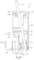
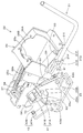
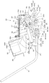

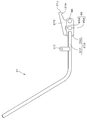


Classifications
-
- E—FIXED CONSTRUCTIONS
- E02—HYDRAULIC ENGINEERING; FOUNDATIONS; SOIL SHIFTING
- E02F—DREDGING; SOIL-SHIFTING
- E02F9/00—Component parts of dredgers or soil-shifting machines, not restricted to one of the kinds covered by groups E02F3/00 - E02F7/00
- E02F9/16—Cabins, platforms, or the like, for drivers
- E02F9/166—Cabins, platforms, or the like, for drivers movable, tiltable or pivoting, e.g. movable seats, dampening arrangements of cabins
-
- B—PERFORMING OPERATIONS; TRANSPORTING
- B60—VEHICLES IN GENERAL
- B60N—SEATS SPECIALLY ADAPTED FOR VEHICLES; VEHICLE PASSENGER ACCOMMODATION NOT OTHERWISE PROVIDED FOR
- B60N2/00—Seats specially adapted for vehicles; Arrangement or mounting of seats in vehicles
- B60N2/64—Back-rests or cushions
- B60N2/646—Back-rests or cushions shape of the cushion
-
- E—FIXED CONSTRUCTIONS
- E02—HYDRAULIC ENGINEERING; FOUNDATIONS; SOIL SHIFTING
- E02F—DREDGING; SOIL-SHIFTING
- E02F9/00—Component parts of dredgers or soil-shifting machines, not restricted to one of the kinds covered by groups E02F3/00 - E02F7/00
- E02F9/16—Cabins, platforms, or the like, for drivers
- E02F9/163—Structures to protect drivers, e.g. cabins, doors for cabins; Falling object protection structure [FOPS]; Roll over protection structure [ROPS]
-
- E—FIXED CONSTRUCTIONS
- E02—HYDRAULIC ENGINEERING; FOUNDATIONS; SOIL SHIFTING
- E02F—DREDGING; SOIL-SHIFTING
- E02F9/00—Component parts of dredgers or soil-shifting machines, not restricted to one of the kinds covered by groups E02F3/00 - E02F7/00
- E02F9/20—Drives; Control devices
- E02F9/2004—Control mechanisms, e.g. control levers
-
- E—FIXED CONSTRUCTIONS
- E02—HYDRAULIC ENGINEERING; FOUNDATIONS; SOIL SHIFTING
- E02F—DREDGING; SOIL-SHIFTING
- E02F9/00—Component parts of dredgers or soil-shifting machines, not restricted to one of the kinds covered by groups E02F3/00 - E02F7/00
- E02F9/20—Drives; Control devices
- E02F9/2004—Control mechanisms, e.g. control levers
- E02F9/2012—Setting the functions of the control levers, e.g. changing assigned functions among operations levers, setting functions dependent on the operator or seat orientation
-
- E—FIXED CONSTRUCTIONS
- E02—HYDRAULIC ENGINEERING; FOUNDATIONS; SOIL SHIFTING
- E02F—DREDGING; SOIL-SHIFTING
- E02F9/00—Component parts of dredgers or soil-shifting machines, not restricted to one of the kinds covered by groups E02F3/00 - E02F7/00
- E02F9/20—Drives; Control devices
- E02F9/2025—Particular purposes of control systems not otherwise provided for
- E02F9/2045—Guiding machines along a predetermined path
-
- E—FIXED CONSTRUCTIONS
- E02—HYDRAULIC ENGINEERING; FOUNDATIONS; SOIL SHIFTING
- E02F—DREDGING; SOIL-SHIFTING
- E02F9/00—Component parts of dredgers or soil-shifting machines, not restricted to one of the kinds covered by groups E02F3/00 - E02F7/00
- E02F9/20—Drives; Control devices
- E02F9/22—Hydraulic or pneumatic drives
- E02F9/2203—Arrangements for controlling the attitude of actuators, e.g. speed, floating function
- E02F9/221—Arrangements for controlling the attitude of actuators, e.g. speed, floating function for generating actuator vibration
-
- G—PHYSICS
- G05—CONTROLLING; REGULATING
- G05G—CONTROL DEVICES OR SYSTEMS INSOFAR AS CHARACTERISED BY MECHANICAL FEATURES ONLY
- G05G5/00—Means for preventing, limiting or returning the movements of parts of a control mechanism, e.g. locking controlling member
- G05G5/005—Means for preventing, limiting or returning the movements of parts of a control mechanism, e.g. locking controlling member for preventing unintentional use of a control mechanism
-
- E—FIXED CONSTRUCTIONS
- E02—HYDRAULIC ENGINEERING; FOUNDATIONS; SOIL SHIFTING
- E02F—DREDGING; SOIL-SHIFTING
- E02F9/00—Component parts of dredgers or soil-shifting machines, not restricted to one of the kinds covered by groups E02F3/00 - E02F7/00
- E02F9/20—Drives; Control devices
- E02F9/22—Hydraulic or pneumatic drives
- E02F9/2264—Arrangements or adaptations of elements for hydraulic drives
- E02F9/2271—Actuators and supports therefor and protection therefor
-
- G—PHYSICS
- G05—CONTROLLING; REGULATING
- G05G—CONTROL DEVICES OR SYSTEMS INSOFAR AS CHARACTERISED BY MECHANICAL FEATURES ONLY
- G05G9/00—Manually-actuated control mechanisms provided with one single controlling member co-operating with two or more controlled members, e.g. selectively, simultaneously
- G05G9/02—Manually-actuated control mechanisms provided with one single controlling member co-operating with two or more controlled members, e.g. selectively, simultaneously the controlling member being movable in different independent ways, movement in each individual way actuating one controlled member only
- G05G9/04—Manually-actuated control mechanisms provided with one single controlling member co-operating with two or more controlled members, e.g. selectively, simultaneously the controlling member being movable in different independent ways, movement in each individual way actuating one controlled member only in which movement in two or more ways can occur simultaneously
- G05G9/047—Manually-actuated control mechanisms provided with one single controlling member co-operating with two or more controlled members, e.g. selectively, simultaneously the controlling member being movable in different independent ways, movement in each individual way actuating one controlled member only in which movement in two or more ways can occur simultaneously the controlling member being movable by hand about orthogonal axes, e.g. joysticks
- G05G2009/04774—Manually-actuated control mechanisms provided with one single controlling member co-operating with two or more controlled members, e.g. selectively, simultaneously the controlling member being movable in different independent ways, movement in each individual way actuating one controlled member only in which movement in two or more ways can occur simultaneously the controlling member being movable by hand about orthogonal axes, e.g. joysticks with additional switches or sensors on the handle
Definitions
- the present invention relates to a work machine such as a backhoe, a skid loader, or a truck loader used for construction work or civil engineering work.
- a working machine disclosed in Patent Document 1 includes a fuselage, a control platform provided on the control console, a driver seat provided on the control console, a control device provided on the side of the driver seat, and a control console. And a support bracket fixed to the frame.
- the control device is pivotally supported by the support bracket so as to be rotatable via a horizontal axis, an operation lever provided in the control box, and is pivotally supported by the control box via a horizontal axis. It has a rotation detection means comprising a cam body, an unload lever fixed to the cam body, and a limit switch.
- the rotation detection means detects when the unload lever is lifted (when the limit switch is turned on) and enters the unload state where the operation by the control device is impossible, and when the unload lever is pushed down (limit) When the switch is turned off), a load state (unload release state) in which an operation by the control device is possible is set.
- the present invention has been made to solve the above-described problems of the prior art, and in a state in which the unload lever is pulled up, the driver moves a part other than the unload lever (for example, an operation lever).
- An object of the present invention is to provide a working machine capable of preventing a shift to a loaded state when gripped and pushed down.
- the work machine includes a driver's seat, a working device having a hydraulic actuator, a support bracket provided on a side of the driver's seat and having a first guide groove, and the support bracket via a first horizontal axis.
- a control box that is pivotally supported and has an operation lever, and an unload that is swingably supported by the control box and that can be operated to supply hydraulic oil to the hydraulic actuator by the swing.
- a lever and a cam body pivotally supported by the control box via a second horizontal axis and having a cam groove, wherein the support bracket is adapted to swing the unload lever.
- the unload lever When the position is changed in the groove and the unload lever is in the pushed down position, it is located in one of the cam grooves, and when in the raised position, it is located in the other of the cam grooves.
- the unload lever has a first guide pin, the position of the unload lever is changed in the first guide groove in response to swinging of the unload lever, and the first load is when the unload lever is in the pushed down position.
- the guide groove is located at one side of the guide groove and at the lifting position
- the second guide pin is located at the other side of the first guide groove, and the first guide groove has the second guide pin in the first guide groove.
- it On the other hand, it has the 1st latching
- the unload lever is pivotally supported between the upper first position and the lower second position with respect to the cam body, and the second guide pin is supported by the unload lever. Is disengaged from the second locking portion when it rotates from the first position to the second position.
- the cam body has a second guide groove, and the unload lever is positioned at one of the second guide grooves when the unload lever is in the first position, and the second When in position, it has a third guide pin located on the other side of the second guide groove.
- the working machine includes a working device having a hydraulic actuator, a driver's seat, a support bracket provided on a side of the driver's seat, and a pivot that is pivotable to the support bracket via a first horizontal axis.
- a position of the load lever, a cam body pivotally supported by the control box via a second horizontal axis and having a cam groove, and a position in the cam groove according to the swing of the unload lever are changed.
- the cam body when the unload lever is in the depressed position, the cam body is positioned on one side of the cam groove and on the other side of the cam groove when in the raised position;
- An urging member for applying an urging force that rotates about the second horizontal axis; a direction of the urging force by the urging member; a first direction for rotating the cam body in one direction; and the cam body in the other direction.
- a switching mechanism that switches to a second direction that pivots to the second direction, wherein the switching mechanism uses the biasing direction of the biasing member as the first direction when the first guide pin is in one of the cam grooves.
- the switching mechanism includes a cam link pivotally supported by the support bracket via a third horizontal axis, and a second guide pin projecting from the cam body.
- the second guide pin is provided below the cam groove, the urging member connects the cam link and the control box, and the cam link is locked to the second guide pin.
- the cam body rotates in conjunction with the cam link via the second guide pin.
- the cam body rotates downward in conjunction with the rotation of the cam link in one direction, and rotates upward in conjunction with the rotation of the cam link in the other direction.
- the biasing member applies a biasing force to rotate the cam link in the one direction when the first guide pin is in the other of the cam grooves, and the first guide pin is in one of the cam grooves. In some cases, an urging force for rotating the cam link in the other direction is applied.
- a widened portion having a width wider than the diameter of the first guide pin is formed.
- the work implement is pivotable through a first horizontal axis to a work device having a hydraulic actuator, a driver's seat, a support bracket provided on a side of the driver's seat, and the support bracket.
- a position of the load lever, a cam body pivotally supported by the control box via a second horizontal axis and having a cam groove, and a position in the cam groove according to the swing of the unload lever are changed.
- a sixth guide pin located on one side of the cam groove when the unload lever is in the pushed down position and located on the other side of the cam groove when in the raised position, Down loading lever, the sixth guide pin has a locking portion for locking to the guide pin when in the other of the cam groove.
- the said unload lever has the lever part pivotally supported by the said cam body via the 5th horizontal axis, and the connecting pin connected with the said lever part is connected to the said cam body
- the lever part has a pivot part pivotally supported on the fifth horizontal axis, and a long hole into which the connecting pin is inserted, and the long hole has a lower first position.
- the connecting pin is located in the first position when the lever portion is in the upward rotation position with the fifth horizontal axis as a fulcrum, and is in the downward rotation position. Sometimes it is located in the second position, and the lock part is locked to the guide pin when the connecting pin is in the first position, and the lock is released when it is in the second position.
- the second guide pin of the unload lever is locked at the second locking portion of the first guide groove, Since the load lever is maintained at the pulled-up position, the first guide pin remains in a state where it is positioned on the other side of the cam groove. Therefore, the rotation of the cam body relative to the support bracket is prevented, and the rotation of the control box pivotally supported by the cam body is prevented. As a result, the control box cannot be rotated unless the unload lever is operated to disengage the second guide pin from the second locking portion, and the parts other than the unload lever (such as the operation lever) are pushed down. In this case, the transition to the load state is prevented.
- the second guide pin of the unload lever is locked to the first locking portion of the first guide groove, so that the unload lever that is caused by vibration during traveling is used. It is possible to prevent the load lever from resonating and the unload lever from jumping up and being unloaded due to the resonance.
- the unload lever is pivotally supported between the upper first position and the lower second position with respect to the cam body, and the second guide pin has the unload lever from the first position to the first position.
- the second guide pin is detached from the second locking portion by rotating the unload lever from the first position to the second position by detaching from the second locking portion when rotating to the second position. Thus, it is possible to shift to the loaded state.
- the cam body has a second guide groove, and the unload lever is located in one of the second guide grooves when the unload lever is in the first position, and the second guide groove when in the second position.
- the rotation range of the unload lever relative to the cam body is restricted to a certain range (range from the first position to the second position) by the second guide groove. Can do. Therefore, it is possible to easily perform an operation of canceling the unload state by the unload lever.
- the unload lever since it has a biasing member that applies a biasing force that pivots upward to hold the unload lever in the first position, the unload lever can be moved in the state where the unload lever is not operated. It can be securely held in one position. Therefore, it is possible to reliably prevent the unload lever from inadvertently descending and shifting to the loaded state.
- the working machine according to the second embodiment of the present invention when the unload lever is in the lifting position, the first guide pin is locked to the other of the cam grooves by the biasing force of the biasing member, and the cam body Is prevented from rotating. Thereby, since the rotation of the control box that pivotally supports the cam body is prevented, the operation lever is prevented from being pushed down (locked state). Thus, it is possible to prevent the driver from inadvertently pushing down the operation lever when the unload lever is in the lifted position.
- the lock portion is locked to the guide pin and the rotation of the cam body is prevented.
- the operation lever is prevented from being pushed down (locked state).
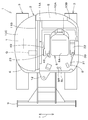
- reference numeral 1 denotes a backhoe exemplified as a work machine (a turning work machine).
- the work machine 1 includes a body (vehicle body) 2, a traveling device 3, and a work device 4.
- the cabin 20 is mounted on the body 2.
- the front side (left side in FIG. 40) of the driver seated in the driver's seat 8 of the cabin 20 is front
- the rear side (right side in FIG. 40) is back
- the left side (front side in FIG. 40) of the driver The left side and the right side of the driver (the back side in FIG. 40) will be described as the right side.
- the horizontal direction 7 (see FIG. 39), which is a direction orthogonal to the front-rear direction, will be described as the body width direction.
- the airframe 2 has a swivel base 6 supported on the frame of the traveling device 3.
- the swivel base 6 is supported through a bearing so as to be turnable to the left and right around a vertical axis.
- a work device 4 is attached to the right front portion of the swivel base 6. In FIG. 18, the working device 4 and the cabin 20 are omitted.
- the cabin 20 is mounted on the left part on the swivel base 6.
- a driver's seat 8 is provided inside the cabin 20.
- a left steering device 22 is provided on the left side of the driver's seat 8.
- a right steering device 23 is provided to the right of the driver's seat 8.
- a passenger entrance 20a is provided on the left side of the cabin 20 and on the left side of the driver's seat 8.
- a door 20A is provided at the entrance 20a.
- the engine room is provided at the rear of the swivel base 6.
- An engine E, a hydraulic pump, an air cleaner, and the like are arranged in the engine room.
- the front side of the engine room is partitioned from the driver's seat 8 by a partition wall 11A.
- the rear side of the engine room is covered with a rear bonnet 10A.
- the left side of the engine room is covered with a left cover body 10B.
- a tank room is provided on the right side of the turntable 6.
- a hydraulic oil tank T In the tank room, a hydraulic oil tank T, a control valve Q, a radiator, and the like are arranged.
- the left side of the tank room is partitioned from the driver's seat 8 by a partition wall 11B.
- the upper side, front side, and right side of the tank room are covered with the right cover body 10C.
- the working device 4 is attached to the front portion of the swivel base 6 via a support bracket 12 and a swing bracket 13.
- the support bracket 12 is fixed to the front portion of the swivel base 6.
- the swing bracket 13 is supported by the support bracket 12 so as to be swingable left and right around the vertical axis.
- the swing bracket 13 is swung left and right by a hydraulic swing cylinder.
- a counterweight W is attached to the rear part of the swivel base 6 in order to balance the weight with the working device 4.
- the traveling device 3 is a crawler type traveling device, and is provided on the right side and the lower left side of the body 2.
- the traveling device 3 is driven by a hydraulic traveling motor.
- a dozer 9 is provided at the front of the traveling device 3.
- the dozer 9 is swung up and down by a dozer cylinder comprising a hydraulic cylinder.
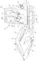
- the work device 4 includes a boom 14, an arm 15, and a work tool 16.
- the work device 4 includes a boom cylinder 17, an arm cylinder 18, and a work tool cylinder 19 as drive mechanisms (hydraulic actuators) for the boom 14 and the like.
- the boom cylinder 17, the arm cylinder 18 and the work tool cylinder 19 are constituted by double-acting hydraulic cylinders.
- the boom 14 is supported by the swing bracket 13 so as to be swingable in the vertical direction.
- the arm 15 is supported on the tip side of the boom 14 so that the base side can swing.
- the bucket as the work tool 16 is attached to the distal end side of the arm 15 so that a squeeze / dump operation is possible.
- a control unit S is provided on the swivel base 6. As shown in FIG. 18, the control section S is partitioned from the engine room by the partition wall 11A, and is partitioned from the tank room by the partition wall 11B.
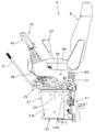
- a driver's seat 8 is provided in the control unit S. As shown in FIGS.
- the driver's seat 8 includes a seat 8 ⁇ / b> A serving as a seat surface and a seat base 8 ⁇ / b> B provided below the seat 8 ⁇ / b> A.
- a left traveling operation lever SL and a right traveling operation lever SR are arranged in front of the driver seat 8.
- the left traveling operation lever SL and the right traveling operation lever SR By operating the left traveling operation lever SL and the right traveling operation lever SR, the left and right crawler traveling bodies 4 can be operated separately or simultaneously.
- Betals are arranged on the left and right feet of the driver's seat 8.
- a cockpit 21 is provided below the driver's seat 8.
- a left steering device 22 and a right steering device 23 are mounted on the control table 21.
- the left steering device 22 is provided on the left side of the driver's seat 8.
- the right steering device 23 is provided on the right side of the driver's seat 8.
- the control table 21 has a substantially flat upper surface portion 21A, a left leg portion 21L, and a right leg portion 21R.
- a storage space 21B having an open front surface is formed below the upper surface portion 21A and between the left leg portion 21L and the right leg portion 21R.
- the storage space 21B stores an air conditioner K1, an electric box K2, and the like.
- the electrical box K2 contains electrical parts for replacement (fuses, relays, etc.).
- the control table 21 is formed of, for example, two metal plates and includes a first member P1 and a second member P2.
- the first member P1 has mounting portions 21a and 21b on the upper surface portion 21A and a left leg portion 21L.
- the second member P2 has a placement portion 21c on the upper surface portion 21A and a right leg portion 21R.
- the first member P1 and the second member P2 are connected via bolts or the like.
- the right steering device 23 has a steering bracket 45.
- the control bracket 45 is provided with a right control valve (first valve) 46 and a work tool operation valve (second valve) 47.
- the steering bracket 45 has a vertical wall 45A and a mounting portion 45B.
- the vertical wall 45 ⁇ / b> A is erected on the cockpit 21.
- the mounting part 45B is fixed to the upper part of the mounting part 21c of the control table 21 with a bolt.
- the right steering valve 46 can be operated by a right operation lever 48.
- the work tool operation valve 47 can be operated by a work operation lever 49.
- the right steering valve 46 is a boom / bucket pilot valve, and the control valve for the boom cylinder 17 and the bucket cylinder 19 can be controlled by the right operation lever 48.
- the work tool operation valve 47 is a pilot valve for driving the dozer 9, and the work operation lever 49 can control the control valve for the dozer cylinder.
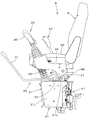
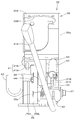
- the left steering device 22 includes a steering box 26, a cam body 33, and an unload lever 31.
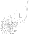
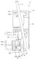
- the steering box 26 is pivotally supported by the first horizontal shaft 27 with respect to the support bracket 25.
- the support bracket 25 has a mounting portion 25 ⁇ / b> A arranged in a horizontal direction and a support portion 25 ⁇ / b> B raised from the mounting portion 25 ⁇ / b> A.
- the mounting portion 25A is fixed to the mounting portion 21b of the control table 21.
- the control box 26 has a left plate member 26a, a right plate member 26b, a mounting plate 26c, and a bearing plate 26d, and is formed in a box shape.
- the left plate member 26 a forms the left side wall of the control box 26.
- the left plate member 26a is indicated by a virtual line (two-dot chain line).
- the right plate member 26b is bent in an L shape in plan view, and forms a right side wall and a back wall of the control box 26. The rear part of the left plate member 26a and the back wall of the right plate member 26b are fixed.
- the mounting plate 26c is fixed so as to connect the front portion of the left plate member 26a and the front portion of the right plate member 26b.
- the interval between the left plate member 26a and the right plate member 26b is narrower than the width of the mounting plate 26c.
- the bearing plate 26d is fixed to the inner surface (front surface) of the back wall of the left plate member 26b.
- the left surface of the bearing plate 26d faces the inner surface (right side surface) of the left plate material 26a.
- the right surface of the bearing plate 26d faces the inner surface (left side surface) of the right plate member 26b.
- a mounting portion 26 ⁇ / b> A for the left control valve 28 is formed on the mounting plate 26 c of the control box 26.
- the left steering valve 28 is mounted on the mounting portion 26A.
- the mounting portion 26A has a substantially semicircular opening 26B with the right front portion opened. Thereby, the left control valve 28 can be mounted on the opening 26B of the mounting portion 26A from the front right side on the driver's seat 8 side.
- the left control valve 28 is a pilot valve for turning and arm operation, and is operated by the left operation lever 30.
- the left operation lever 30 is attached to the upper part of the mounting portion 26 ⁇ / b> A of the control box 26.
- the support portion 25 ⁇ / b> B of the support bracket 25 is provided with a first horizontal shaft 27 and a first guide groove 24.
- the first horizontal axis 27 extends in the horizontal direction (machine width direction).
- the first guide groove 24 is provided above the first horizontal shaft 27.
- the first guide groove 24 includes a front groove 24A, an intermediate groove 24B, and a rear groove 24C.
- the front groove 24A extends upward and slightly forward from the front portion of the support portion 25B.
- the intermediate groove 24B extends rearward and slightly upward from the upper end of the front groove 24A.
- the rear groove 24C extends downward and slightly rearward from the rear end of the intermediate groove 24B.
- the lower end of the rear groove 24C is located slightly above the lower end of the front groove 24A.
- a second guide pin 44 described later is inserted into the first guide groove 24.
- the front groove 24A functions as a first locking portion that locks the second guide pin 44 on one side (front side) of the first guide groove 24.
- the rear groove 24B functions as a second locking portion that locks the second guide pin 44 on the other side (rear side) of the first guide groove 24.
- a boss portion 26 ⁇ / b> C is provided at the lower rear portion of the control box 26.
- the boss portion 26C extends in the lateral direction (machine width direction) so as to connect the left plate member 26a and the bearing plate 26d.
- the boss portion 26 ⁇ / b> C is rotatably fitted on the outer periphery of the first horizontal shaft 27. Thereby, the control box 26 is rotatably supported with the first horizontal shaft 27 as a fulcrum (around the first horizontal shaft 27).
- a second horizontal shaft 32 extending in the horizontal direction (machine width direction) is provided at the rear of the control box 26.
- the second horizontal axis 32 is located behind the first horizontal axis 27 and behind the first guide groove 24.
- a base portion (rear portion) of the cam body 33 is pivotally supported at the rear portion of the control box 26 via a second horizontal shaft 32.
- the cam body 33 extends forward and downward from the second horizontal shaft 32.
- a base portion (a lever base portion 31B described later) of the unload lever 31 is pivotally supported via a third horizontal shaft 36 at a lower portion (a pivot supporting portion 51 described later) of the cam body 33.
- the unload lever 31 is swingably supported by the control box 26 via the cam body 33.
- the unload lever 31 can be operated by supplying the hydraulic oil to the hydraulic actuator of the work device 4 by the swing.
- the cam body 33 has a cam groove 34 formed from one side (rear part) to the other side (front part).
- the support portion 25B of the support bracket 25 is provided with a first guide pin 35 having an axis extending in the body width direction.
- the first guide pin 35 is located in front of the first horizontal shaft 27 and at an intermediate height between the second horizontal shaft 32 and the first horizontal shaft 27. Further, as shown in FIG.
- the first guide pin 35 is located between the front groove 24A and the rear groove 24C of the first guide groove 24 and below the intermediate groove 24B.
- the first guide pin 35 is inserted into the cam groove 34 via a cam follower.
- the cam body 33 and the like are omitted.
- the cam groove 34 has a first cam groove 34A and a second cam groove 34B.
- the first cam groove 34 ⁇ / b> A is formed on one side (rear part) of the cam body 33.
- the second cam groove 34 ⁇ / b> B is formed on the other side (front portion) of the cam body 33. Specifically, the second cam groove 34 ⁇ / b> B extends forward from the front end portion of the first cam groove 34.
- the first cam groove 34 ⁇ / b> A is formed in an arc shape centered on the axis of the second horizontal shaft 32.
- the second cam groove 34B is formed to have an arc shape centered on the axis of the first horizontal shaft 27 when the first guide pin 35 is in the second cam groove 34B (see FIGS. 13 to 15).
- the cam groove 34 is formed to have a length that allows the control box 26 to rotate around a required angle, for example, about 50 °.
- the cam body 33 has the second horizontal shaft 32 as a fulcrum (around the second horizontal shaft 32), and one (upward) ).
- the cam body 33 rotates, the position of the first guide pin 35 changes within the cam groove 34.
- the cam groove 34 moves relatively from one (rear) to the other (front). More specifically, it moves relatively from the first cam groove 34A to the second cam groove 34B. That is, when the unload lever 31 is in the pushed down position (see FIG.
- the first guide pin 35 is located in the first cam groove 34A on one side (rear side) of the cam groove 34 and is in the raised position ( 13) is located in the second cam groove 34B on the other (front) side of the cam groove. The movement of the first guide pin 35 will be described in detail later.
- a stay 37 having a substantially L-shaped side view is fixed to the upper surface of the rear portion (base portion) of the cam body 33.
- a return spring 38 as an urging member is interposed between the upper portion of the stay 37 and the mounting plate 26c of the control box 26.
- the upper portion of the stay 37 can come into contact with a stopper 54 (see FIG. 8) provided on the right plate member 26a.
- the unload lever 31 is urged by the return spring 38 in the push-down direction (counterclockwise direction in FIG. 9).
- a locking plate 53 that locks one end of a tension spring 50 as an urging member described later is fixed to the front portion of the stay 37.
- the cam body 33 has two through holes penetrating from one surface to the other surface.
- the rear through hole constitutes a pivot portion 51 on which a third horizontal shaft 36, which will be described later, is pivotally supported.
- the front through hole constitutes a second guide groove 52 that guides the movement of the third guide pin 40 described later.
- the second guide groove 52 is composed of a long hole provided in front of the pivotal support portion 51.
- the second guide groove 52 is formed in a substantially elliptical shape that is long in the vertical direction, and has an upper first position 52A and a lower second position 52B. A third guide pin 40 described later is inserted into the second guide groove 52.
- the unload lever 31 has a lever body 31A and a lever base 31B.
- the lever main body 31 ⁇ / b> A is a part that is gripped when the driver operates the unload lever 31.
- the rear end portion of the lever main body 31A is fixed to the front portion of the lever base portion 31B.
- the lever main body 31 ⁇ / b> A extends from the front portion of the lever base portion 31 ⁇ / b> B toward the front upper side of the control box 26.
- the lever base 31B is formed of a plate-like member, and is arranged with one surface facing the right side (the support portion 25B side of the support bracket 25) and the other surface facing the left side (the cam body 33 side). Has been. That is, the lever base portion 31B is disposed between the support portion 25B of the support bracket 25 and the cam body 33 in the body width direction. As shown in FIGS. 5 and 12, the lever base 31 ⁇ / b> B has a third horizontal shaft 36, a second guide pin 44, and a third guide pin 40.
- the third horizontal shaft 36 is provided at the lower rear portion of the lever base 31B and protrudes toward the left (cam body 33 side).
- the third horizontal shaft 36 is located in front of the first horizontal shaft 27 and below the cam groove 34.
- the third horizontal axis 36 is located behind the third guide pin 40.
- the third horizontal axis 36 is a bolt in this embodiment.
- the second guide pin 44 is provided at the upper rear portion of the lever base portion 31B and protrudes toward the right side (the support portion 25B side).
- the second guide pin 44 is provided above the third horizontal shaft 36.
- the protruding end (right end) of the second guide pin 44 is inserted into the first guide groove 24 and can move in the first guide groove 24 from the front groove 24A to the rear groove 24C.
- the second guide pin 44 When the second guide pin 44 is positioned in the front groove (first locking portion) 24A of the first guide groove 24, the second guide pin 44 is locked in the front groove 24A, and the rear groove (second locking portion) 24C. When positioned, it is locked in the rear groove 24C.
- the third guide pin 40 is provided at the front lower portion of the lever base 31B and protrudes toward the left (cam body 33 side).
- the third guide pin 40 is provided below and in front of the second guide pin 44.
- the 3rd guide pin 40 consists of a stepped volt
- a concave notch 31b that is notched forward is formed at the rear of the lever base 31B. By forming the notch 31b, it is possible to prevent the first guide pin 35 from interfering with the lever base 31B when it moves along the cam groove 34.
- the lever base portion 31B is provided with a locking portion 31C for locking one end portion of the biasing member (tensile spring) 50.
- the locking portion 31C extends upward from the front upper portion of the lever base portion 31B.
- the pivotal support portion 51 is positioned in front of the first guide pin 35, below the second guide pin 44, and behind the third guide pin 40.
- the unload lever 31 (the lever main body 31A and the lever base portion 31B) is rotatable with respect to the cam body 33 with the pivot portion 51 (the third horizontal shaft 36) as a fulcrum.
- the second guide groove 52 is inserted with a shaft portion of a bolt constituting the third guide pin 40.
- the outer diameter of the head portion of the bolt constituting the third guide pin 40 is larger than the inner diameter of the second guide groove 52, and the head portion is located on the outer surface (left surface) of the cam body 33 on the left outside the second guide groove 52. ).
- the third guide pin 40 has one of the second guide grooves 52 (first position 52A) when the unload lever 31 (the lever main body 31A and the lever base 31B) is rotated downward with the third horizontal shaft 36 as a fulcrum. ) To the other (second position 52B), and when rotated upward, moves from the other (second position 52B) to one (first position 52A).
- the third guide pin 40 has one of the second guide grooves 52 (first position 52A) when the unload lever 31 is in the upward rotation position (first position) with the third horizontal shaft 36 as a fulcrum.
- the second guide groove 52 is located on the other side (second position 52B) when in the downward rotation position (second position).
- the rotation range around the third horizontal shaft 36 of the unload lever 31 is the upper limit position when the third guide pin 40 is at the first position 52A, and the third guide pin 40 is at the second position 52B. At some point, it is the lower limit position. In other words, the rotation range of the unload lever 31 around the third horizontal axis 36 is restricted by the second guide groove 52.
- a tension spring 50 as an urging member is interposed between the locking portion 31 ⁇ / b> C of the lever base portion 31 ⁇ / b> B and the locking plate 53. The tension spring 50 biases the unload lever 31 in a direction in which the unload lever 31 is rotated upward with the third horizontal shaft 36 as a fulcrum.
- the unload lever 31 is rotated upward by the urging force of the tension spring 50 with the third horizontal shaft 36 as a fulcrum, and this rotation is performed by the third guide pin 40 at the first position 52A of the second guide groove 52. It stops when it reaches.
- the third guide pin 40 moves from the first position 52A to the second position 52B.
- a rotation detection device 55 including a limit switch is provided on the upper portion of the bearing plate 26d of the control box 26.
- the switch piece at the tip of the rotation detection device 55 is engaged with the stay 37.
- the rotation detection device 55 is connected to the electronic control units of the left steering device 22 and the right steering device 23.
- the rotation detection device 55 operates an unload valve provided in the hydraulic circuit of each of the control devices 22 and 23 by being turned off from on.
- a gas cylinder (gas spring) 39 as an urging member is provided between the support portion 25B of the support bracket 25 and the control box 26.
- the gas cylinder 39 connects a pin 39a projecting from the front lower portion of the support portion 25B and a pin 39b projecting from an upper position of the control box 26.
- the gas cylinder 39 has an urging force in the extending direction, and assists in turning the left steering device 22 upward. Headed pins are used as the pins 39a and 39b. Thereby, securing of the mounting strength of the gas cylinder 39 and facilitation of disassembly and assembly are achieved.
- the first contact mechanism 41 is provided on the support portion 25 ⁇ / b> B of the support bracket 25.
- the first contact mechanism 41 holds the left steering device 22 in a use position (see FIGS. 8 to 11) described later.
- the first contact mechanism 41 includes a mounting plate 41A fixed to the upper portion of the support portion 25B, and a first contact member 41B attached to the mounting plate 41A.
- the first contact member 41B contacts the first contact plate 70 fixed to the right plate member 26b of the control box 26 when the left steering device 22 is in the use position.
- a second contact mechanism 42 is provided on the mounting portion 25A of the support bracket 25.
- the second contact mechanism 42 holds the left steering device 22 in an upward rotation position (avoidance position) (see FIG. 13) described later.
- the second contact mechanism 42 includes an attachment plate 42A fixed to the rear portion of the attachment portion 25A, and a second contact member 42B attached to the attachment plate 42A.
- the second contact member 42B contacts the second contact plate 56 fixed to the left plate member 26a of the control box 26 when the left control device 22 is in an upward rotation position (see FIG. 13) described later.
- a guide member 43 is provided on the surface (right side surface) of the support bracket 25 on the driver's seat 8 side.
- the guide member 43 guides the hose connected to the left steering valve 28.
- the guide member 43 protrudes toward the driver's seat 8 from the mounting portion 25A of the support bracket 25.
- the first horizontal shaft 27, the cam body 33, the unload lever 31, the return spring 38, the rotation detection device 55, the first contact mechanism 41, the second contact mechanism 42, and the like constitute the rotation mechanism 29. ing.
- the left steering device 22 is rotated upward (withdrawn) by the turning mechanism 29, the entrance 20a on the left front side of the driver's seat 8 (that is, the front side of the left steering device 22) is widely secured. It is avoided that the left steering device 22 prevents the driver from getting on and off.
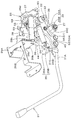
- FIGS. 8 to 11 show a state in which the unload lever 31 is in the pushed down position.
- the states shown in FIGS. 8 to 11 are used positions (normal work positions) when working with the work implement 1.
- the first abutment mechanism 41 restricts the downward rotation of the control box 26 around the first horizontal axis 27, and the left control device 22 is held in the use position.
- the left steering device 22 is held at the use position.
- the first guide pin 35 is located at the base end (rear end) of the first cam groove 34A.
- the second guide pin 44 is locked to the front groove (first locking portion) 24 ⁇ / b> A of the first guide groove 24.
- the unload lever 31 is restricted from rotating downward (the counterclockwise direction in FIG. 9 and the clockwise direction in FIG. 11) by the first locking portion 24A and the stopper 54.
- the rotation detection device 55 is on, and the upward rotation of the unload lever 31 is not detected. That is, the unload lever 31 is in the unload release position.
- the left operation lever 30 for the turning / arm by operating the left operation lever 30 for the turning / arm, the turning of the turntable 6 and the raising / lowering of the arm 15 can be activated, and the operation by the right steering device 23 for the boom / bucket. Is enabled. ⁇ The unload lever is in the raised position> Next, a state where the unload lever 31 is in the lifted position will be described.
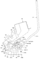
- FIG. 13 shows a state where the unload lever 31 is in the lifted position.
- the state shown in FIG. 13 is the upward rotation position (avoidance position).
- the left steering device 22 is held in the upward rotation position by the second contact member 42B of the second contact mechanism 42 coming into contact with the second contact plate 56 fixed to the left plate member 26a.
- the rotation detection device 55 is turned off, and the unload state by the unload lever 31 is detected. That is, the unload lever 31 is in the unload position.
- the left operation lever 30 for the turn / arm is operated, the turntable 6 and the arm 15 are disabled.
- the boom 14 and the bucket 16 are disabled.
- the unload lever 31 is urged by the urging force of the tension spring 50 in a direction of rotating upward with the third horizontal shaft 36 as a fulcrum. Therefore, the third guide pin 40 provided on the lever base 31 ⁇ / b> B of the unload lever 31 is held at the first position 52 ⁇ / b> A above the second guide groove 52.
- the first guide pin 35 is located near the front end of the second cam groove 34B.
- the second guide pin 44 is locked to the rear groove (second locking portion) 25 ⁇ / b> C of the first guide groove 24. Since the second guide pin 44 is provided on the lever base 31B of the unload lever 31, it cannot be separated from the rear groove (second locking portion) 25C unless the unload lever 31 is operated.
- the control box 26 cannot be rotated downward without holding the unload lever 31 (locked state).
- the driver is prevented from depressing a portion other than the unload lever 31 (the left operation lever 30 or the like) to enter the unload release state (load state).
- ⁇ Operation of the left control device when the unload lever is pushed down> ⁇ First stage>
- the driver slightly pushes down the unload lever 31 against the urging force of the tension spring 50. Specifically, as shown in FIG. 14, the unload lever 31 is moved from the first position (the third guide pin 40 is in the first position 52A) to the second position (the third guide pin 40 is in the second position 52B).
- the first guide pin 35 moves to the vicinity of the boundary between the second cam groove 34B and the first cam groove 34A.
- the second guide pin 44 moves to the vicinity of the boundary between the intermediate groove 24B of the first guide groove 24 and the front groove (first locking portion) 24A.
- the control box 26 further rotates downward.
- ⁇ Fourth stage> When the unload lever 31 is further pushed down from the state of FIG. 16, the cam body 33 further rotates downward as shown in FIG.
- the first guide pin 35 moves upward along the first cam groove 34A.
- the second guide pin 44 moves downward along the front groove (first locking portion) 24 ⁇ / b> A of the first guide groove 24.
- the second guide pin 44 when the unload lever 31 is in the lifted position, the second guide pin 44 has the rear groove (second locking portion) 24C of the first guide groove 24.
- the control box 26 is prevented from turning downward (locked state). As a result, it is possible to prevent the driver from inadvertently depressing a portion other than the unload lever 31 (such as the left operation lever 30) to enter the load state.
- the unload lever 31 is rotated downward to move the third guide pin 40 from the first position 52A to the second position 52B, whereby the second guide pin 44 moves above the first guide groove 24 and is separated from the rear groove (second locking portion) 24C, and the locked state is released. That is, the locked state is not released unless the driver performs an operation of pushing down the unload lever 31. For this reason, it is possible to reliably prevent the driver from turning down the steering box 26 into a loaded state by pushing down a portion other than the unload lever 31 (such as the left operation lever 30). Further, when releasing the locked state, a special unlocking operation is not required other than the pushing-down operation of the unload lever 31, so that the operability is excellent.
- a biasing member (a tension spring 50) that biases the unload lever 31 in a direction in which the unload lever 31 is rotated upward with the third horizontal shaft 36 as a fulcrum (a direction in which the unload lever 31 is held at the first position).
- the locked state can be reliably maintained. That is, unless the driver pushes down the unload lever 31 against the biasing member (the tension spring 50), the third guide pin 40 is maintained at the first position 52A. (Second engagement portion) The state (locked state) engaged with 24C is reliably maintained.
- Second Embodiment are views showing a second embodiment of the present invention.
- the basic configuration of the work machine 1 shown in FIGS. 1, 2, 39, and 40 is common to the first embodiment and the second embodiment.
- the second embodiment will be described focusing on the configuration different from the first embodiment.
- symbol is attached
- subjected and description is abbreviate
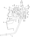
- the left steering device 22 of the second embodiment includes a steering box 26, a cam body 80, and an unload lever 31.
- the control box 26 is pivotally supported with respect to the support bracket 25.
- the support bracket 25 has a mounting portion 25A arranged in a horizontal direction and a support portion 25B raised from the mounting portion 25A.
- the mounting portion 25A is fixed to the upper surface portion 21A of the control table 21.
- the control box 26 includes a left plate member 26a, a right plate member 26b, a mounting plate 26c, and a bearing plate 26d, and is formed in a box shape.
- the left plate member 26 a forms the left side wall of the control box 26.
- the left plate member 26a is indicated by a virtual line (two-dot chain line), and in FIG. 24, the left plate member 26a is omitted.
- the support portion 25B of the support bracket 25 is provided with a first horizontal shaft 27 extending in the lateral direction (machine width direction).
- a boss portion 26 ⁇ / b> C is provided at the lower rear portion of the control box 26.
- the boss portion 26C extends in the lateral direction (machine width direction) so as to connect the left plate member 26a and the bearing plate 26d.
- the boss portion 26 ⁇ / b> C is rotatably fitted on the outer periphery of the first horizontal shaft 27.
- the control box 26 is rotatably supported with the first horizontal shaft 27 as a fulcrum (around the first horizontal shaft 27).
- a fourth guide pin 61 having a shaft center extending in the body width direction is projected on the support portion 25B of the support bracket 25, a fourth guide pin 61 having a shaft center extending in the body width direction is projected.
- the fourth guide pin 61 is located in front of the first horizontal shaft 27 and at an intermediate height between the second horizontal shaft 32 and the first horizontal shaft 27.
- a second horizontal shaft 32 extending in the horizontal direction (machine width direction) is provided at the rear portion of the control box 26.
- the second horizontal axis 32 is located on the rear upper side of the first horizontal axis 27.
- a base portion (rear portion) of the cam body 80 is pivotally supported at the rear portion of the control box 26 via the second horizontal shaft 32.
- the cam body 80 extends forward and downward from the second horizontal shaft 32.
- a base portion (rear portion) of the unload lever 31 is fixed to the front portion of the cam body 80.
- the unload lever 31 is swingably supported by the control box 26 via the cam body 80.
- the unload lever 31 can be operated by supplying the hydraulic oil to the hydraulic actuator of the work device 4 by the swing.
- the cam body 80 has a cam groove 81 formed from one side (rear part) to the other side (front part).
- the cam groove 81 is provided in front of the second horizontal shaft 32 (on the unload lever 31 side).
- the fourth guide pin 61 is inserted into the cam groove 81 via a cam follower.
- the cam groove 81 is formed to have a length that allows the control box 26 to rotate around a necessary angle, for example, about 50 °.
- the cam groove 81 has an intermediate groove part 81a, a rear groove part 81b, and a front groove part 81c.
- the intermediate groove 81a is formed so as to go from one side (rear part) of the cam body 80 to the other side (front part).
- the intermediate groove 81a has an arc shape centered on the axis of the first horizontal shaft 27 in a state where the fourth guide pin 61 is positioned in the intermediate groove 81a (see FIGS. 25 to 27). Is formed.
- the rear groove portion 81b is formed in an arc shape centering on the axis of the second horizontal shaft 32 so as to extend upward from the rear end portion of the intermediate groove portion 81a.
- the front groove portion 81c is formed to extend downward from the front end portion of the intermediate groove portion 81a.
- the cam groove 81 is formed in a substantially Z shape in a side view by the intermediate groove portion 81a, the rear groove portion 81b, and the front groove portion 81c.
- the widths of the intermediate groove portion 81 a and the rear groove portion 81 b are formed to be approximately equal to the diameter of the fourth guide pin 61.
- the front groove portion 81 c has a widened portion 81 e that is formed wider than the diameter of the fourth guide pin 61.
- the widened portion 81e is formed by extending the rear portion of the inner edge of the front groove portion 81c rearward in an arc shape, and the portion expanded in the arc shape has a locking recess 81f to which the fourth guide pin 61 is locked. It is composed. Since the front groove portion 81c has the widened portion 81e, as shown in FIG. 28, the outer periphery of the fourth guide pin 61 and the front groove portion 81c are in a state where the fourth guide pin 61 is locked to the locking recess 81f. A gap G is formed between the inner edge.
- the cam body 80 rotates about the second horizontal shaft 32 (around the second horizontal shaft 32) and on one side (upward). Move. As the cam body 80 rotates, the position of the fourth guide pin 61 changes within the cam groove 81. More specifically, the cam groove 81 moves relatively from one side to the other side (specifically, from the rear groove portion 81b to the front groove portion 81c via the intermediate groove portion 81a). When the unload lever 31 is pushed down, the fourth guide pin 61 moves relatively in the cam groove 81 from the other side to the other side (specifically, from the front groove portion 81c to the rear groove portion 81b via the intermediate groove portion 81a). Moving.
- the fourth guide pin 61 is located in one of the cam grooves 81 (rear groove portion 81b).
- the fourth guide pin 61 is positioned on the other side of the cam groove 81 (front groove portion 81c).
- the fourth guide pin 61 is located between one and the other of the cam grooves 81 (intermediate groove 81a).
- a stay 37 having a substantially L shape in a side view is fixed on the upper surface of the rear portion (base portion) of the cam body 80.
- the upper portion of the stay 37 can come into contact with a stopper 54 (see FIG. 24, etc.) provided on the right plate member 26a.
- the cam body 80 has a fifth guide pin 62 extending in the lateral direction (machine body width direction) at the front lower side of the first horizontal shaft 27.
- the fifth guide pin 62 protrudes below the front groove portion 81 c of the cam groove 81.
- a fourth horizontal shaft 63 extending in the lateral direction (machine width direction) is provided at the front lower portion of the support portion 25B of the support bracket 25.
- the fourth horizontal axis 63 is located in front of the first horizontal axis 27 and in front of the fifth guide pin 62. Further, the fourth horizontal shaft 63 is located in the lower front side of the cam groove 81.
- a cam link 64 is pivotally supported on the front lower portion of the support portion 25 ⁇ / b> B of the support bracket 25 via a fourth horizontal shaft 63.
- the cam link 64 has a locking portion 64 ⁇ / b> A that is locked to the fifth guide pin 62.
- the locking portion 64A is formed of a substantially U-shaped notch in a side view.
- the fifth guide pin 62 moves relative to the notch of the locking portion 64A when the cam link 64 rotates about the fourth horizontal shaft 63 (around the fourth horizontal shaft 63). That is, the fifth guide pin 62 itself does not move, but the fifth guide pin 62 moves inside the notch of the locking portion 64A by moving the locking portion 64A.
- the cam link 64 rotates in conjunction with the rotation of the cam body 80 via the fifth guide pin 62 when the locking portion 64A is locked to the fifth guide pin 62.
- the cam body 80 rotates downward in conjunction with the rotation of the cam link 64 in one direction around the fourth horizontal axis 63.
- the cam body 80 rotates upward in conjunction with the rotation of the cam link 64 in the other direction opposite to the one direction.
- the one direction is a direction in which the locking portion 64A of the cam link 64 descends, and is the clockwise direction in FIG.
- the other direction is a direction in which the locking portion 64A of the cam link 64 moves upward, and is the counterclockwise direction in FIG.
- An urging member 82 made of a gas cylinder is provided between the cam link 64 and the control box 26.
- the urging member 82 connects a pin 82 a projecting from the cam link 64 and a pin 82 b projecting closer to the upper portion of the control box 26.
- the urging member 82 has an urging force in the extending direction, and assists in turning the left steering device 22 (the steering box 26) upward.
- the cam link 64 and the fifth guide pin 62 are configured such that the direction of the urging force by the urging member 82 is a direction in which the cam body 80 is rotated to one side (upward) (hereinafter also referred to as a first direction).
- a switching mechanism for switching to the other (downward) direction (hereinafter also referred to as the second direction) is configured.
- the urging direction by the urging member 82 is the first direction when the fourth guide pin 61 is in one of the cam grooves 81 (rear groove portion 81b), and the fourth guide pin 61 is the other of the cam grooves 81.
- the second direction is set.
- the urging member 82 rotates the cam link 64 in the one direction (the clockwise direction in FIG. 23) when the fourth guide pin 61 is in one of the cam grooves 81 (rear groove 81b). Give the urging force to move.
- the urging force for rotating the cam link 64 in one direction is transmitted to the cam body 80 via the fifth guide pin 62, and in the direction (second direction) for rotating the cam body 80 in the other direction (downward). It becomes an energizing force.
- the urging member 82 is attached to rotate the cam link 64 in the other direction (counterclockwise direction in FIG. 23). Grant power.
- the urging force for rotating the cam link 64 in the other direction is transmitted to the cam body 80 via the fifth guide pin 62, and in the direction (first direction) for rotating the cam body 80 in one direction (upward). It becomes an energizing force.
- the fourth guide pin 61 is locked to the locking recess 81f of the front groove 81c.
- a rotation detection device 55 including a limit switch is provided on the upper part of the bearing plate 26d fixed to the right plate member 26a of the control box 26, a rotation detection device 55 including a limit switch is provided.
- the switch piece at the tip of the rotation detection device 55 is engaged with the stay 37.
- the rotation detection device 55 is connected to the electronic control units of the left steering device 22 and the right steering device 23.
- the rotation detection device 55 operates an unload valve provided in the hydraulic circuit of each of the control devices 22 and 23 by being turned off from on.
- a first contact mechanism 41 is provided on the support portion 25 ⁇ / b> B of the support bracket 25.
- the first contact mechanism 41 holds the left steering device 22 at a use position (see FIGS. 22 and 23) described later.
- the first contact mechanism 41 includes a mounting plate 41A fixed to the upper portion of the support portion 25B, and a first contact member 41B attached to the mounting plate 41A.
- the first contact member 41B contacts the first contact plate 70 fixed to the right plate member 26b of the control box 26 when the left steering device 22 is in the use position.
- the mounting portion 25A of the support bracket 25 is provided with a second contact mechanism.
- the second contact mechanism 42 holds the left steering device 22 in an upward rotation position (avoidance position) (see FIG. 28) described later.
- the second contact mechanism 42 includes an attachment plate 42A fixed to the rear portion of the attachment portion 25A, and a second contact member 42B attached to the attachment plate 42A.
- the second contact member 42B contacts the second contact plate 56 fixed to the left plate member 26a of the control box 26 when the left control device 22 is in the upward rotation position (see FIG. 28).
- first horizontal shaft 27, cam body 80, unload lever 31, rotation detection device 55, first contact mechanism 41, second contact mechanism 42, and the like rotate the left steering device 22. 29 is configured.
- the left steering device 22 is rotated upward (withdrawn) by the turning mechanism 29, the entrance 20a on the left front side of the driver's seat 8 (that is, the front side of the left steering device 22) is widely secured.
- the left steering device 22 does not prevent the driver from getting on and off.
- the left steering device 22 is in a use position (normal work position) when working with the work machine 1 in the state shown in FIGS.
- the first abutment mechanism 41 restricts the downward rotation of the control box 26 around the first horizontal axis 27, and the left control device 22 is held in the use position.
- the left steering device 22 is held at the use position.
- the fourth guide pin 61 is located at the base end (rear end) of the rear groove portion 81 b of the cam groove 81. Further, the unload lever 31 is restricted by the stopper 54 from turning downward (counterclockwise in FIG. 23). In this use position, the rotation detection device 55 is on, and the upward rotation of the unload lever 31 is not detected. That is, the unload lever 31 is in the unload release position. In this state, by operating the left operation lever 30 for the turning / arm, the turning of the turntable 6 and the raising / lowering of the arm 15 can be activated, and the operation by the right steering device 23 for the boom / bucket. Is enabled.
- the cam body 80 fixed to the unload lever 31 is also rotated upward.
- the fourth guide pin 61 moves relative to the cam body 80 and moves in the cam groove 81 from the rear part to the front part.
- the fourth guide pin 61 first moves from the base end (rear end) of the rear groove portion 81b to the rear portion of the intermediate groove portion 81a, and the arc groove centered on the axis of the first horizontal shaft 27. Is engaged with the intermediate groove 81a. Thereby, the upper rotation of the control box 26 around the first horizontal axis 27 is allowed, and the rotation is started.
- the fourth guide pin 61 moves from the rear part of the intermediate groove part 81a to the middle part. From the state (first stage) where the fourth guide pin 61 shown in FIG. 25 is at the proximal end (rear end) of the rear groove part 81b to the state (second stage) where it is in the middle part of the intermediate groove part 81a shown in FIG.
- the cam link 64 rotates in the other direction (counterclockwise direction in FIGS. 23, 25, and 26) with the fourth horizontal shaft 63 as a fulcrum.
- the cam body 80 rotates upward with the second horizontal shaft 32 as a fulcrum.
- the fourth guide pin 61 moves from the front part of the intermediate groove part 81a to the front groove part 81c.
- the cam link 64 uses the fourth horizontal shaft 63 as a fulcrum in the other direction (counterclockwise in FIGS. 23, 25, and 26). Direction).
- the cam body 80 rotates upward with the second horizontal shaft 32 as a fulcrum.
- Rotation detection device 55 is turned off when the control box 26 is rotated upward from the position (use position) shown in FIG. 23 and detects the unload state by the unload lever 31. After the unload lever 31 is in the unloaded state, the left steering device 22 is further rotated upward together with the control box 26, so that the left steering device 22 passes through the position shown in FIGS. 25 to 27 and then the upward rotation shown in FIG. Position (avoidance position). In this upward rotation position, the left steering device 22 is retracted upward so as to widen the entrance 20.
- the swivel base 6 and the arm 15 cannot be operated even if the left operation lever 30 for the turn / arm is operated. Further, even if the right steering device 23 for the boom / bucket is operated, the boom 14 and the bucket 16 are disabled. In the operation of pulling up the unload lever 31 from the use position to the upward rotation position (avoidance position), the urging member 82 extends. The urging member 82 assists the operation of rotating the control box 26 upward around the first horizontal axis 27 until it reaches the maximum extended state.
- the biasing member 82 applies a biasing force that rotates the cam link 64 around the fourth horizontal shaft 63 in the process of pulling up the unload lever 31 from the use position to the upward rotation position (avoidance position). is doing. Specifically, the urging member 82 applies an urging force that rotates the cam link 64 in the one direction when the fourth guide pin 61 is in the front groove portion 81c. On the other hand, when the fourth guide pin 61 is in the rear groove 81b, an urging force for rotating the cam link 64 in the other direction is applied. That is, the urging member 82 changes the direction of the urging force with respect to the cam link 64 in the process in which the fourth guide pin 61 moves from the rear part to the front part of the intermediate groove part 81a.
- the rotation direction of the cam link 64 changes (reverse rotation), and the rotation direction of the cam body 80 interlocks with the change (reverse rotation) of the cam link 64. Will also change (reverse).
- the change in the biasing direction of the biasing member 82 is caused by a change in the positional relationship between the pins 82a and 82b at both ends of the biasing member 82. 23, 25, and 26, when the pin 82a is located behind the pin 82b, the urging member 82 attaches the cam link 64 to the other direction (direction in which the locking portion 64A is lowered). Rush. On the other hand, as shown in FIGS.
- the urging member 82 urges the cam link 64 in the one direction (direction in which the locking portion 64A rises). To do.
- the change in the positional relationship between the pins 82a and 82b occurs in the process in which the fourth guide pin 61 moves from the rear part to the front part of the intermediate groove part 81a.
- the left steering device 22 (control box 26) reaches the upward rotation position (avoidance position)
- the second contact member 42B is fixed to the left plate member 26a.
- the left steering device 22 (steering box 26) is held at the avoidance position.
- the fourth guide pin 61 is in the front groove portion 81c.
- the urging member 82 urges the cam link 64 in the one direction (the direction in which the locking portion 64A rises). This urging force is transmitted to the cam body 80 via the fifth guide pin 62.
- the unloading lever 31 is biased by the biasing member 82 (see FIG. 28) from the state where the left steering device 22 (the steering box 26) is in the upward rotation position (see FIG. 28). Press down a little against the force to stretch). As a result, the cam body 80 rotates downward with the second horizontal shaft 32 as a fulcrum. By this rotation, the fourth guide pin 61 moves from the locking recess 81f of the front groove 81c to the intermediate groove 81a, and the locked state is released (see FIG. 27). As a result, the unload lever 31 can be further pushed down.
- the steering box 26 rotates downward, and the left steering device 22 becomes the use position as shown in FIG. Thereby, the rotation detection device 55 is turned on, and the unload state is not detected. That is, the unload release state is established.
- the left operation lever 30 for the turning / arm by operating the left operation lever 30 for the turning / arm, the turning of the turntable 6 and the raising / lowering of the arm 15 can be operated, and the operation by the right control device 23 for the boom / bucket can be performed. Operable.
- the urging force of the urging member 82 causes the fourth guide pin 61 to move into the locking recess 81f of the front groove portion 81c. It is held in the locked state (locked state), and the downward rotation of the control box 26 is prevented. As a result, it is possible to prevent the driver from inadvertently depressing the left operation lever 30 to enter the unload release state.
- the unload lever 31 is pushed down against the urging force of the urging member 82 to disengage the fourth guide pin 61 from the locking recess 81f of the front groove portion 81c.
- the lock state is released with. That is, when the driver is not performing an operation for releasing the locked state, since the downward rotation of the control box 26 is prevented, the driver cannot push down the left operation lever 30. Therefore, it is possible to reliably prevent the driver from inadvertently depressing the left operation lever 30 to enter the unload release state. In addition, when releasing the locked state, no special operation is required other than the push-down operation of the unload lever 31, so that the operability is excellent.
- the driver depresses the unload lever 31 against the urging force of the urging member 82, the state where the fourth guide pin 61 is locked to the front groove portion 81c by the urging force of the urging member 82 is maintained. Therefore, the locked state is reliably maintained.
- the biasing member 82 applies a biasing force that rotates the cam link 64 in the one direction. This urging force acts as a force for rotating the cam body 80 downward. Thereby, the unload lever 31 is urged in the push-down direction (counterclockwise direction in FIG. 23).
- the urging member 82 can be easily assembled. That is, when the urging member 82 such as a gas cylinder is assembled, the urging member 82 must be assembled while being shortened against the urging force (force to be extended). Therefore, the biasing member 82 is assembled in the most extended state (see FIG. 28) so that the degree of shortening is reduced. In this state, since the fourth guide pin 61 is located in the front groove portion 81c, it becomes play when the widened portion 81e is assembled. Therefore, the urging member 82 can be easily assembled.
- the left steering device 22 of the third embodiment includes a steering box 26, a cam body 90, and an unload lever 31.
- the control box 26 is pivotally supported with respect to the support bracket 25.
- the support bracket 25 includes a mounting portion 25A arranged in a horizontal direction and a support portion 25B raised from the mounting portion 25A.
- the mounting portion 25A is fixed to the upper surface portion 21A of the control table 21.
- the control box 26 includes a left plate member 26a, a right plate member 26b, a mounting plate 26c, and a bearing plate 26d, and is formed in a box shape.
- the left plate member 26 a forms the left side wall of the control box 26.
- the left plate member 26a is indicated by a virtual line (two-dot chain line), and the left plate member 26a is omitted in FIG.
- the support portion 25B of the support bracket 25 is provided with a first horizontal shaft 27 extending in the lateral direction (machine width direction).
- a boss portion 26 ⁇ / b> C is provided at the lower rear portion of the control box 26.
- the boss portion 26C extends in the lateral direction (machine width direction) so as to connect the left plate member 26a and the bearing plate 26d.
- the boss portion 26 ⁇ / b> C is rotatably fitted on the outer periphery of the first horizontal shaft 27.
- the control box 26 is rotatably supported with the first horizontal shaft 27 as a fulcrum (around the first horizontal shaft 27).
- a second horizontal shaft 32 extending in the horizontal direction (machine width direction) is provided at the rear of the control box 26.
- the second horizontal axis 32 is located on the rear upper side of the first horizontal axis 27.
- a base portion (rear portion) of the cam body 90 is pivotally supported at the rear portion of the control box 26 via the second horizontal shaft 32.
- the cam body 90 extends forward and downward from the second horizontal shaft 32.
- a base portion (rear portion) of the unload lever 31 is pivotally supported at the front portion of the cam body 90 via a fifth horizontal shaft 60.
- the unload lever 31 is swingably supported by the control box 26 via the cam body 90.
- the unload lever 31 can be operated by supplying the hydraulic oil to the hydraulic actuator of the work device 4 by the swing.
- the cam body 90 has a cam groove 91 formed from one side (rear part) to the other side (front part).
- a sixth guide pin 92 having an axial center extending in the body width direction protrudes from the support portion 25B of the support bracket 25.
- the sixth guide pin 92 is located in front of the first horizontal shaft 27 and at an intermediate height between the second horizontal shaft 32 and the first horizontal shaft 27.
- the sixth guide pin 92 is inserted into the cam groove 91 via a cam follower.
- the cam groove 91 has a first cam groove 91A and a second cam groove 91B.
- the first cam groove 91 ⁇ / b> A is formed on one side (rear part) of the cam body 90.
- the second cam groove 91 ⁇ / b> B is formed on the other side (front part) of the cam body 90.
- the second cam groove 91B extends forward from the front end portion of the first cam groove 91A.
- the first cam groove 91 ⁇ / b> A is formed in an arc shape centered on the axis of the second horizontal shaft 32.
- the second cam groove 91B is formed to have an arc shape centered on the axis of the first horizontal shaft 27 when the sixth guide pin 92 is in the second cam groove 91B (see FIGS. 37 and 38).
- the cam groove 91 is formed to have a length that allows the control box 26 to turn around a required angle, for example, about 50 °.
- the cam body 90 rotates about the second horizontal shaft 32 (around the second horizontal shaft 32) and one (upward). Move.
- the position of the sixth guide pin 92 changes within the cam groove 91.
- the cam groove 91 moves relatively from one (rear) to the other (front). More specifically, it moves relatively from the first cam groove 91A to the second cam groove 91B. That is, the sixth guide pin 92 is positioned in the first cam groove 91A on one side (rear side) of the cam groove 91 when the unload lever 31 is in the pushed down position, and the other of the cam grooves when in the lifted position. It is located in the (front) second cam groove 91B.
- a stay 37 having a substantially L-shaped side view is fixed to the upper surface of the rear portion (base portion) of the cam body 90.
- a return spring 38 is interposed between the upper portion of the stay 37 and the mounting plate 26 c of the control box 26.
- the upper portion of the stay 37 can come into contact with a stopper 54 (see FIG. 35) provided on the right plate member 26a.
- the unload lever 31 is urged by the return spring 38 in the push-down direction (counterclockwise direction in FIG. 34).
- a locking plate 53 that locks one end of a tension spring 93 described later is fixed to the front portion of the stay 37.
- the fifth horizontal axis 60 is located at the front lower side of the first horizontal axis 27 and at the front lower side of the cam groove 91.
- the fifth horizontal axis 60 is a bolt in this embodiment.
- the cam body 90 has a connecting pin 94 extending in the body width direction in front of the fifth horizontal shaft 60.
- the connecting pin 94 is a bolt and protrudes to the left of the cam body 90.
- the unload lever 31 has a lever portion 31D and a lock portion 31E.
- the lever portion 31D has a lever main body 31F and a lever base portion 31G.
- the lever body 31F is a part that is gripped when the driver operates the unload lever 31.
- the rear end portion of the lever main body 31F is fixed to the front portion of the lever base portion 31G.
- the lever body 31F extends from the front part of the lever base part 31G toward the front upper side of the control box 26.
- the lever main body 31F is provided with a locking portion 31I for locking one end of a tension spring 93 to be described later.
- the locking portion 31I extends upward from a midway portion in the length direction of the lever main body 31F.
- the lever base 31G is formed of a plate-like member, and is arranged with one surface facing the right side (cam body 90 side) and the other surface facing the left side (opposite side of the cam body 90). . As shown in FIG. 36, the lever base 31G has two through holes penetrating from one surface toward the other surface.
- the one (rear) through-hole constitutes a pivot portion 96 on which the fifth horizontal shaft 60 is pivotally supported.
- the other (front) through hole constitutes a connecting portion 95 that is connected to the cam body 90 via a connecting pin 94.
- the pivotal support portion 96 is provided behind the connecting pin 94 and in front of and below the sixth guide pin 92.
- the lever portion 31D (the lever main body 31F and the lever base portion 31G) is rotatable about the pivot portion 96 (the fifth horizontal shaft 60).
- the connection part 95 is comprised from the long hole provided in the front of the pivot part 96 (henceforth the long hole 95).
- the long hole 95 is formed in a substantially elliptical shape that is long in the vertical direction, and has a lower first position 95A and an upper second position 95B.
- a shaft portion of a bolt constituting the connecting pin 94 is inserted into the elongated hole 95.
- the outer diameter of the head of the bolt constituting the connecting pin 94 is larger than the inner diameter of the long hole 95, and the head is in contact with the other surface of the lever base 31 ⁇ / b> G on the left outside the long hole 95.
- the connecting pin 94 moves relatively from the first position 95A to the second position 95B of the elongated hole 95 when the lever portion 31D is rotated downward with the fifth horizontal shaft 60 as a fulcrum, and rotates upward. When it is moved, it relatively moves from the second position 95B to the first position 95A. In other words, the connecting pin 94 is located at the first position 95A when the lever portion 31D is in the upward rotation position about the fifth horizontal shaft 60, and is located at the second position 95B when it is in the downward rotation position. To do.
- the rotation range around the fifth horizontal shaft 60 of the lever portion 31D is the lower limit position when the connecting pin 94 is at the first position 95A, and the upper limit position when the connecting pin 94 is at the second position 95B. It becomes.
- the turning range of the lever portion 31 ⁇ / b> D around the fifth horizontal axis 60 is regulated by the long hole 95.
- the lock portion 31E is formed of a plate-like member, and is disposed with one surface facing the right side (cam body 90 side) and the other surface facing the left side (opposite side of the cam body 90). .
- One surface (right side surface) of the front portion of the lock portion 31E is fixed to the upper portion of the other surface (left side surface) of the lever base portion 31G.
- the rear portion of the lock portion 31E extends in a direction approaching the sixth guide pin 92, and includes a locking claw 31H and a guide portion 31J.
- the locking claw 31H is bent downward in a claw shape from the rear end portion of the lock portion 31E, and can be locked to the sixth guide pin 92 from above.
- the locking claw 31H is locked to the sixth guide pin 92 when the sixth guide pin 92 is in the other (front) second cam groove 91B of the cam groove 91. More specifically, the locking claw 31H is in the upward rotation position described later when the connecting pin 94 is in the first position 95A (when the lever portion 31D is in the upward rotation position with the fifth horizontal shaft 60 as a fulcrum). ) And is locked by the sixth guide pin 92 (see FIG.
- the guide portion 31J is formed on an inclined surface extending upward and rearward from the tip (lower end) of the locking claw 31H.
- the guide portion 31J functions as a guide that guides the locking claw 31H to the locking position (see FIG. 37) in the process in which the locking claw 31H is locked to the sixth guide pin 92.
- the guide portion 31J has a sixth guide pin 92 in the process in which the sixth guide pin 92 moves from the first cam groove 91A to the second cam groove 91B as shown by an imaginary line (two-dot chain line) in FIG. It slides while contacting the outer peripheral surface of the guide pin 92.
- the locking claw 31H gets over the sixth guide pin 92 and is locked to the sixth guide pin 92 from above as shown in FIG.
- the lever portion 31D and the lock portion 31E of the unload lever 31 are formed by separate members and integrated, but may be formed by a single member. Further, the lever main body 31F and the lever base 31G may be formed by one member. Moreover, you may form the whole unload lever 31 with one member.
- a tension spring 93 as an urging member is interposed between the locking portion 31I of the lever portion 31D and the locking plate 53. The tension spring 93 biases the lever portion 31D in a direction to rotate upward with the fifth horizontal shaft 60 as a fulcrum. The lever portion 31D is rotated upward about the fifth horizontal shaft 60 by the urging force of the tension spring 93.
- a rotation detection device 55 including a limit switch is provided on the upper part of the bearing plate 26d of the control box 26, a rotation detection device 55 including a limit switch is provided.
- the switch piece at the tip of the rotation detection device 55 is engaged with the stay 37.
- the rotation detection device 55 is connected to the electronic control units of the left steering device 22 and the right steering device 23.
- the rotation detection device 55 operates an unload valve provided in the hydraulic circuit of each of the control devices 22 and 23 by being turned off from on.
- a gas cylinder 39 as an urging member is provided between the support portion 25B of the support bracket 25 and the control box 26, a gas cylinder 39 as an urging member is provided.
- the gas cylinder 39 connects a pin 39a projecting from the front lower portion of the support portion 25B and a pin 39b projecting from an upper position of the control box 26.
- the gas cylinder 39 has an urging force in the extending direction, and assists in turning the left steering device 22 upward.
- the first contact mechanism 41 is provided on the support portion 25B of the support bracket 25.
- the first contact mechanism 41 holds the left steering device 22 in a use position (see FIGS. 33 and 34) described later.
- the first contact mechanism 41 includes a mounting plate 41A fixed to the upper portion of the support portion 25B, and a first contact member 41B attached to the mounting plate 41A.
- the first contact member 41B contacts the first contact plate 70 fixed to the right plate member 26b of the control box 26 when the left steering device 22 is in the use position.
- the mounting portion 25A of the support bracket 25 is provided with a second contact mechanism.
- the second contact mechanism 42 holds the left steering device 22 in an upward rotation position (avoidance position) (see FIG. 37) described later.
- the second contact mechanism 42 includes an attachment plate 42A fixed to the rear portion of the attachment portion 25A, and a second contact member 42B attached to the attachment plate 42A.
- the second abutting member 42B abuts on the second abutting plate 56 fixed to the left plate member 26a of the maneuvering box 26 when the left steering device 22 is in an upward rotation position (see FIG. 37) described later.
- the first horizontal shaft 27, the cam body 90, the unload lever 31, the return spring 38, the rotation detection device 55, the first contact mechanism 41, the second contact mechanism 42, and the like constitute the rotation mechanism 29. ing.
- the left steering device 22 is rotated upward (withdrawn) by the turning mechanism 29, the entrance 20a on the diagonally left front side of the driver's seat 8 (that is, the front side of the left steering device 22) is widely secured.
- the left steering device 22 does not prevent the driver from getting on and off.
- the state shown in FIGS. 33 and 34 is a use position (normal work position) when working with the work implement 1.
- the first abutment mechanism 41 restricts the downward rotation of the control box 26 around the first horizontal axis 27, and the left control device 22 is held in the use position.
- the first contact member 41 ⁇ / b> B contacts the first contact plate 70, the left steering device 22 is held at the use position.
- the sixth guide pin 92 is located at the base end (rear end) of the first cam groove 91A. Further, the unload lever 31 is restricted from rotating downward (counterclockwise in FIG. 34) by the stopper 54. The lever portion 31D is biased upward (clockwise in FIG. 34) by the tension spring 93 with the fifth horizontal shaft 60 as a fulcrum. As a result, the connecting pin 94 is held at the first position 95 ⁇ / b> A below the elongated hole 95.
- the rotation detection device 55 is on, and the upward rotation of the unload lever 31 is not detected. That is, the unload lever 31 is in the unload release position.
- the left operation lever 30 for the turning / arm by operating the left operation lever 30 for the turning / arm, the turning of the turntable 6 and the raising / lowering of the arm 15 can be activated, and the operation by the right steering device 23 for the boom / bucket. Is enabled.
- the gas cylinder 39 In the operation of pulling up the unload lever 31 from the use position to the upward rotation position (avoidance position), the gas cylinder 39 extends. The gas cylinder 39 assists the operation of rotating the control box 26 upward around the first horizontal axis 27 until the gas cylinder 39 reaches the maximum extension state. And the 2nd contact member 42B of the 2nd contact mechanism 42 contacts the 2nd contact board 56 fixed to the left board
- the driver slightly pushes down the unload lever 31 against the urging force of the tension spring 93 from the state where the left steering device 22 is in the upward rotation position (see FIG. 37).
- the unload lever 31 rotates downward (counterclockwise in FIG. 37) until the connecting pin 94 reaches the second position 95B of the elongated hole 95 with the fifth horizontal shaft 60 as a fulcrum.
- the latching claw 31H moves upward and moves away from the sixth guide pin 92, and the locked state is released (see FIG. 38).
- the unload lever 31 can be further pushed down.
- the cam body 90 rotates downward with the second horizontal shaft 32 as a fulcrum (center).
- the sixth guide pin 92 moves relative to the cam body 90 and moves from the second cam groove 91B to the first cam groove 91A.
- the steering box 26 rotates downward, and the left steering device 22 becomes the use position (see FIG. 34).
- the rotation detection device 55 is turned on, and the unload state is not detected. That is, the unload release state is established.
- the left operation lever 30 for the turning / arm the turning of the turntable 6 and the raising / lowering of the arm 15 can be operated, and the operation by the right control device 23 for the boom / bucket can be performed. Operable.
- the locking claw 31H of the lock portion 31E is locked to the sixth guide pin 92 (locked state).
- the downward rotation of the control box 26 is prevented.
- the lever main body 31F is rotated downward to move the connecting pin 94 from the first position 95A to the second position 95B, thereby locking the sixth guide pin 92.
- the claw 31H is unlocked (the locked state is released). That is, when the driver does not perform the operation of releasing the locked state (the operation of pushing down the lever main body 31F), the driver can push down the left operation lever 30 because the downward rotation of the control box 26 is prevented. Can not. Therefore, it is possible to reliably prevent the driver from inadvertently depressing the left operation lever 30 to enter the unload release state.
- a special unlocking operation is not required other than the pushing-down operation of the lever main body 31F, so that the operability is excellent.
- the lever main body 31F includes a biasing member (a tension spring 93) that biases the lever main body 31F in a direction to rotate upward with the fifth horizontal shaft 60 as a fulcrum, the locked state can be reliably maintained. It can. That is, as long as the driver does not push down the lever main body 31F against the biasing member (the tension spring 93), the connecting pin 94 is maintained at the second position 95B, so that the locking claw 31H of the lock portion 31E is the sixth. The state (locked state) engaged with the guide pin 92 is reliably maintained.
- a biasing member a tension spring 93
Landscapes
- Engineering & Computer Science (AREA)
- Mining & Mineral Resources (AREA)
- Structural Engineering (AREA)
- General Engineering & Computer Science (AREA)
- Civil Engineering (AREA)
- Automation & Control Theory (AREA)
- Physics & Mathematics (AREA)
- General Physics & Mathematics (AREA)
- Mechanical Engineering (AREA)
- Transportation (AREA)
- Aviation & Aerospace Engineering (AREA)
- Component Parts Of Construction Machinery (AREA)
- Operation Control Of Excavators (AREA)
Abstract
La présente invention vise à empêcher une transition vers un état de chargement lorsqu'un levier autre qu'un levier de déchargement est saisi et poussé vers le bas. La présente invention comprend : un boîtier de commande (26) qui est maintenu de manière pivotante par une équerre de support (12), qui a une première rainure de guidage (24), par l'intermédiaire d'un premier arbre horizontal (27) ; un levier de déchargement (31) qui est maintenu de manière oscillante par le boîtier de commande ; et un corps de came (33) qui est maintenu de manière pivotante par le boîtier de commande par l'intermédiaire d'un second arbre horizontal (32) et qui a une rainure de came. L'équerre de support a une première broche de guidage (35) qui est positionnée sur un côté de la rainure de came lorsque le levier de déchargement est dans une position poussée vers le bas, et qui est positionnée sur l'autre côté de la rainure de came lorsque le levier de déchargement est dans une position tirée vers le haut. Le levier de déchargement comprend une seconde broche de guidage (44) qui est positionnée sur un côté de la première rainure de guidage lorsque le levier de déchargement est dans la position poussée vers le bas, et qui est positionnée sur l'autre côté de la première rainure de guidage lorsque le levier non chargé est dans la position tirée vers le haut. La première rainure de guidage a une première partie de verrouillage (24A) qui verrouille la seconde broche de guidage sur un côté de la première rainure de guidage, et une seconde partie de verrouillage (24B) qui verrouille la seconde broche de guidage sur l'autre côté de la première rainure de guidage.
Priority Applications (2)
| Application Number | Priority Date | Filing Date | Title |
|---|---|---|---|
| EP15887801.7A EP3279401B1 (fr) | 2015-03-30 | 2015-12-25 | Engin de chantier |
| US15/630,958 US10407871B2 (en) | 2015-03-30 | 2017-06-23 | Work machine |
Applications Claiming Priority (6)
| Application Number | Priority Date | Filing Date | Title |
|---|---|---|---|
| JP2015-069933 | 2015-03-30 | ||
| JP2015-069934 | 2015-03-30 | ||
| JP2015069933A JP6336939B2 (ja) | 2015-03-30 | 2015-03-30 | 作業機 |
| JP2015069934A JP6336940B2 (ja) | 2015-03-30 | 2015-03-30 | 作業機 |
| JP2015170458A JP6259432B2 (ja) | 2015-08-31 | 2015-08-31 | 作業機 |
| JP2015-170458 | 2015-08-31 |
Related Child Applications (1)
| Application Number | Title | Priority Date | Filing Date |
|---|---|---|---|
| US15/630,958 Continuation US10407871B2 (en) | 2015-03-30 | 2017-06-23 | Work machine |
Publications (1)
| Publication Number | Publication Date |
|---|---|
| WO2016157659A1 true WO2016157659A1 (fr) | 2016-10-06 |
Family
ID=57005551
Family Applications (1)
| Application Number | Title | Priority Date | Filing Date |
|---|---|---|---|
| PCT/JP2015/086226 Ceased WO2016157659A1 (fr) | 2015-03-30 | 2015-12-25 | Engin de chantier |
Country Status (3)
| Country | Link |
|---|---|
| US (1) | US10407871B2 (fr) |
| EP (1) | EP3279401B1 (fr) |
| WO (1) | WO2016157659A1 (fr) |
Cited By (1)
| Publication number | Priority date | Publication date | Assignee | Title |
|---|---|---|---|---|
| WO2019130814A1 (fr) * | 2017-12-27 | 2019-07-04 | 株式会社クボタ | Dispositif de levier et machine de travail le comportant |
Families Citing this family (9)
| Publication number | Priority date | Publication date | Assignee | Title |
|---|---|---|---|---|
| US10837158B2 (en) * | 2018-02-07 | 2020-11-17 | Manitou Equipment America, Llc | Loader, operator seat assembly with integrated, non-electronic hydraulic pilot valves |
| KR102016287B1 (ko) * | 2019-07-02 | 2019-08-29 | 안국수 | 굴삭기용 콘솔박스 |
| WO2022113922A1 (fr) * | 2020-11-27 | 2022-06-02 | 株式会社クボタ | Machine de travail |
| CN116710617A (zh) * | 2021-01-27 | 2023-09-05 | 株式会社久保田 | 中立返回机构 |
| EP4361357A4 (fr) * | 2021-06-24 | 2025-07-23 | Kubota Kk | Dispositif de levier et engin de chantier |
| CN117897535A (zh) * | 2022-02-10 | 2024-04-16 | 日立建机株式会社 | 工程机械 |
| EP4549667A1 (fr) * | 2022-06-30 | 2025-05-07 | Kubota Corporation | Dispositif de levier et engin de chantier le comprenant |
| WO2024143188A1 (fr) * | 2022-12-26 | 2024-07-04 | 株式会社クボタ | Dispositif de levier et engin de mise en œuvre équipé de ce dernier |
| GB2634582A (en) * | 2023-10-10 | 2025-04-16 | Bamford Excavators Ltd | A seat console assembly |
Citations (3)
| Publication number | Priority date | Publication date | Assignee | Title |
|---|---|---|---|---|
| JP2000328604A (ja) * | 1999-05-17 | 2000-11-28 | Shin Caterpillar Mitsubishi Ltd | 建設機械 |
| JP2002021119A (ja) * | 2000-07-12 | 2002-01-23 | Tokai Rika Co Ltd | コンソールボックス装置 |
| JP2012127137A (ja) * | 2010-12-16 | 2012-07-05 | Hitachi Constr Mach Co Ltd | 建設機械 |
Family Cites Families (11)
| Publication number | Priority date | Publication date | Assignee | Title |
|---|---|---|---|---|
| KR100559293B1 (ko) * | 2003-07-25 | 2006-03-15 | 볼보 컨스트럭션 이키프먼트 홀딩 스웨덴 에이비 | 높이 조절이 가능한 조종레버를 갖는 중장비용 콘솔박스 |
| JP4080974B2 (ja) * | 2003-08-12 | 2008-04-23 | 株式会社クボタ | ホイール式作業機 |
| JP3985762B2 (ja) * | 2003-09-29 | 2007-10-03 | コベルコ建機株式会社 | 建設機械の操縦装置 |
| WO2007037107A1 (fr) * | 2005-09-29 | 2007-04-05 | Kubota Corporation | Machine de travaux de type a roues |
| JP4648963B2 (ja) | 2008-03-27 | 2011-03-09 | 株式会社クボタ | 作業機の操縦部構造 |
| JP5841008B2 (ja) * | 2012-05-28 | 2016-01-06 | ヤンマー株式会社 | 旋回作業車 |
| JP5918072B2 (ja) * | 2012-08-06 | 2016-05-18 | 株式会社クボタ | 作業機 |
| US20140263606A1 (en) * | 2013-03-14 | 2014-09-18 | Clark Equipment Company | Valve identification system |
| JP5962686B2 (ja) * | 2014-01-30 | 2016-08-03 | コベルコ建機株式会社 | 建設機械の電装品冷却構造 |
| GB2531763A (en) * | 2014-10-29 | 2016-05-04 | Bamford Excavators Ltd | Working machine |
| GB2531762A (en) * | 2014-10-29 | 2016-05-04 | Bamford Excavators Ltd | Working machine |
-
2015
- 2015-12-25 EP EP15887801.7A patent/EP3279401B1/fr active Active
- 2015-12-25 WO PCT/JP2015/086226 patent/WO2016157659A1/fr not_active Ceased
-
2017
- 2017-06-23 US US15/630,958 patent/US10407871B2/en active Active
Patent Citations (3)
| Publication number | Priority date | Publication date | Assignee | Title |
|---|---|---|---|---|
| JP2000328604A (ja) * | 1999-05-17 | 2000-11-28 | Shin Caterpillar Mitsubishi Ltd | 建設機械 |
| JP2002021119A (ja) * | 2000-07-12 | 2002-01-23 | Tokai Rika Co Ltd | コンソールボックス装置 |
| JP2012127137A (ja) * | 2010-12-16 | 2012-07-05 | Hitachi Constr Mach Co Ltd | 建設機械 |
Non-Patent Citations (1)
| Title |
|---|
| See also references of EP3279401A4 * |
Cited By (3)
| Publication number | Priority date | Publication date | Assignee | Title |
|---|---|---|---|---|
| WO2019130814A1 (fr) * | 2017-12-27 | 2019-07-04 | 株式会社クボタ | Dispositif de levier et machine de travail le comportant |
| JP2019116753A (ja) * | 2017-12-27 | 2019-07-18 | 株式会社クボタ | レバー装置及びそれを備えた作業機 |
| US11473268B2 (en) | 2017-12-27 | 2022-10-18 | Kubota Corporation | Lever device and working machine having the same |
Also Published As
| Publication number | Publication date |
|---|---|
| EP3279401A1 (fr) | 2018-02-07 |
| EP3279401A4 (fr) | 2018-11-21 |
| US20170285681A1 (en) | 2017-10-05 |
| US10407871B2 (en) | 2019-09-10 |
| EP3279401B1 (fr) | 2023-05-31 |
Similar Documents
| Publication | Publication Date | Title |
|---|---|---|
| EP3279401B1 (fr) | Engin de chantier | |
| JP6827916B2 (ja) | レバー装置及びそれを備えた作業機 | |
| KR100398935B1 (ko) | 건설기계 | |
| JP6336939B2 (ja) | 作業機 | |
| WO2017051931A1 (fr) | Véhicule de terrassement | |
| JP6259432B2 (ja) | 作業機 | |
| EP2058214B1 (fr) | Structure de butee pour une cabine pouvant basculer | |
| JP2008247310A (ja) | 荷役車両 | |
| KR20180071678A (ko) | 지게차용 사이드 도어 | |
| JP6336940B2 (ja) | 作業機 | |
| US7959218B2 (en) | Tilt lock structure of driver's cabin | |
| US12435489B2 (en) | Lever device and working machine including the same | |
| JP4535457B2 (ja) | 作業機械における乗降遮断装置 | |
| JP7636217B2 (ja) | アウトリガ用敷板設置装置、アウトリガ | |
| JP7628884B2 (ja) | アウトリガ用敷板設置装置、アウトリガ | |
| JP2009046932A (ja) | 産業車両用キャビンドア開閉装置 | |
| JP5129767B2 (ja) | 運搬車及び運搬車のスライドドアの開閉方法 | |
| JP7727615B2 (ja) | 車両用ポップアップフード装置 | |
| JP7567950B2 (ja) | 規制装置 | |
| CN101525008B (zh) | 驾驶室的倾斜锁止结构 | |
| JP4734200B2 (ja) | 荷役車両 | |
| KR200342314Y1 (ko) | 자동차의 테일 게이트 래치 장치 | |
| WO2026009761A1 (fr) | Boîte de console et machine de construction dotée de celle-ci | |
| JP2022143383A (ja) | カム調整機構、カム調整方法、アウトリガ | |
| CN116065643A (zh) | 挖土机 |
Legal Events
| Date | Code | Title | Description |
|---|---|---|---|
| 121 | Ep: the epo has been informed by wipo that ep was designated in this application |
Ref document number: 15887801 Country of ref document: EP Kind code of ref document: A1 |
|
| REEP | Request for entry into the european phase |
Ref document number: 2015887801 Country of ref document: EP |
|
| NENP | Non-entry into the national phase |
Ref country code: DE |