WO2016157767A1 - 電子ミラー装置 - Google Patents
電子ミラー装置 Download PDFInfo
- Publication number
- WO2016157767A1 WO2016157767A1 PCT/JP2016/001424 JP2016001424W WO2016157767A1 WO 2016157767 A1 WO2016157767 A1 WO 2016157767A1 JP 2016001424 W JP2016001424 W JP 2016001424W WO 2016157767 A1 WO2016157767 A1 WO 2016157767A1
- Authority
- WO
- WIPO (PCT)
- Prior art keywords
- light
- control
- filter
- display unit
- state
- Prior art date
- Legal status (The legal status is an assumption and is not a legal conclusion. Google has not performed a legal analysis and makes no representation as to the accuracy of the status listed.)
- Ceased
Links
Images


Classifications
-
- B—PERFORMING OPERATIONS; TRANSPORTING
- B60—VEHICLES IN GENERAL
- B60R—VEHICLES, VEHICLE FITTINGS, OR VEHICLE PARTS, NOT OTHERWISE PROVIDED FOR
- B60R1/00—Optical viewing arrangements; Real-time viewing arrangements for drivers or passengers using optical image capturing systems, e.g. cameras or video systems specially adapted for use in or on vehicles
- B60R1/02—Rear-view mirror arrangements
- B60R1/08—Rear-view mirror arrangements involving special optical features, e.g. avoiding blind spots, e.g. convex mirrors; Side-by-side associations of rear-view and other mirrors
- B60R1/083—Anti-glare mirrors, e.g. "day-night" mirrors
- B60R1/088—Anti-glare mirrors, e.g. "day-night" mirrors using a cell of electrically changeable optical characteristic, e.g. liquid-crystal or electrochromic mirrors
-
- B—PERFORMING OPERATIONS; TRANSPORTING
- B60—VEHICLES IN GENERAL
- B60R—VEHICLES, VEHICLE FITTINGS, OR VEHICLE PARTS, NOT OTHERWISE PROVIDED FOR
- B60R1/00—Optical viewing arrangements; Real-time viewing arrangements for drivers or passengers using optical image capturing systems, e.g. cameras or video systems specially adapted for use in or on vehicles
- B60R1/02—Rear-view mirror arrangements
- B60R1/04—Rear-view mirror arrangements mounted inside vehicle
-
- B—PERFORMING OPERATIONS; TRANSPORTING
- B60—VEHICLES IN GENERAL
- B60R—VEHICLES, VEHICLE FITTINGS, OR VEHICLE PARTS, NOT OTHERWISE PROVIDED FOR
- B60R1/00—Optical viewing arrangements; Real-time viewing arrangements for drivers or passengers using optical image capturing systems, e.g. cameras or video systems specially adapted for use in or on vehicles
- B60R1/12—Mirror assemblies combined with other articles, e.g. clocks
-
- B—PERFORMING OPERATIONS; TRANSPORTING
- B60—VEHICLES IN GENERAL
- B60R—VEHICLES, VEHICLE FITTINGS, OR VEHICLE PARTS, NOT OTHERWISE PROVIDED FOR
- B60R1/00—Optical viewing arrangements; Real-time viewing arrangements for drivers or passengers using optical image capturing systems, e.g. cameras or video systems specially adapted for use in or on vehicles
- B60R1/12—Mirror assemblies combined with other articles, e.g. clocks
- B60R1/1207—Mirror assemblies combined with other articles, e.g. clocks with lamps; with turn indicators
-
- G—PHYSICS
- G02—OPTICS
- G02F—OPTICAL DEVICES OR ARRANGEMENTS FOR THE CONTROL OF LIGHT BY MODIFICATION OF THE OPTICAL PROPERTIES OF THE MEDIA OF THE ELEMENTS INVOLVED THEREIN; NON-LINEAR OPTICS; FREQUENCY-CHANGING OF LIGHT; OPTICAL LOGIC ELEMENTS; OPTICAL ANALOGUE/DIGITAL CONVERTERS
- G02F1/00—Devices or arrangements for the control of the intensity, colour, phase, polarisation or direction of light arriving from an independent light source, e.g. switching, gating or modulating; Non-linear optics
- G02F1/01—Devices or arrangements for the control of the intensity, colour, phase, polarisation or direction of light arriving from an independent light source, e.g. switching, gating or modulating; Non-linear optics for the control of the intensity, phase, polarisation or colour
- G02F1/15—Devices or arrangements for the control of the intensity, colour, phase, polarisation or direction of light arriving from an independent light source, e.g. switching, gating or modulating; Non-linear optics for the control of the intensity, phase, polarisation or colour based on an electrochromic effect
- G02F1/153—Constructional details
- G02F1/1533—Constructional details structural features not otherwise provided for
-
- G—PHYSICS
- G02—OPTICS
- G02F—OPTICAL DEVICES OR ARRANGEMENTS FOR THE CONTROL OF LIGHT BY MODIFICATION OF THE OPTICAL PROPERTIES OF THE MEDIA OF THE ELEMENTS INVOLVED THEREIN; NON-LINEAR OPTICS; FREQUENCY-CHANGING OF LIGHT; OPTICAL LOGIC ELEMENTS; OPTICAL ANALOGUE/DIGITAL CONVERTERS
- G02F1/00—Devices or arrangements for the control of the intensity, colour, phase, polarisation or direction of light arriving from an independent light source, e.g. switching, gating or modulating; Non-linear optics
- G02F1/01—Devices or arrangements for the control of the intensity, colour, phase, polarisation or direction of light arriving from an independent light source, e.g. switching, gating or modulating; Non-linear optics for the control of the intensity, phase, polarisation or colour
- G02F1/15—Devices or arrangements for the control of the intensity, colour, phase, polarisation or direction of light arriving from an independent light source, e.g. switching, gating or modulating; Non-linear optics for the control of the intensity, phase, polarisation or colour based on an electrochromic effect
- G02F1/153—Constructional details
- G02F1/157—Structural association of cells with optical devices, e.g. reflectors or illuminating devices
-
- G—PHYSICS
- G09—EDUCATION; CRYPTOGRAPHY; DISPLAY; ADVERTISING; SEALS
- G09G—ARRANGEMENTS OR CIRCUITS FOR CONTROL OF INDICATING DEVICES USING STATIC MEANS TO PRESENT VARIABLE INFORMATION
- G09G3/00—Control arrangements or circuits, of interest only in connection with visual indicators other than cathode-ray tubes
- G09G3/20—Control arrangements or circuits, of interest only in connection with visual indicators other than cathode-ray tubes for presentation of an assembly of a number of characters, e.g. a page, by composing the assembly by combination of individual elements arranged in a matrix no fixed position being assigned to or needed to be assigned to the individual characters or partial characters
- G09G3/34—Control arrangements or circuits, of interest only in connection with visual indicators other than cathode-ray tubes for presentation of an assembly of a number of characters, e.g. a page, by composing the assembly by combination of individual elements arranged in a matrix no fixed position being assigned to or needed to be assigned to the individual characters or partial characters by control of light from an independent source
- G09G3/36—Control arrangements or circuits, of interest only in connection with visual indicators other than cathode-ray tubes for presentation of an assembly of a number of characters, e.g. a page, by composing the assembly by combination of individual elements arranged in a matrix no fixed position being assigned to or needed to be assigned to the individual characters or partial characters by control of light from an independent source using liquid crystals
- G09G3/3611—Control of matrices with row and column drivers
-
- B—PERFORMING OPERATIONS; TRANSPORTING
- B60—VEHICLES IN GENERAL
- B60R—VEHICLES, VEHICLE FITTINGS, OR VEHICLE PARTS, NOT OTHERWISE PROVIDED FOR
- B60R1/00—Optical viewing arrangements; Real-time viewing arrangements for drivers or passengers using optical image capturing systems, e.g. cameras or video systems specially adapted for use in or on vehicles
- B60R1/12—Mirror assemblies combined with other articles, e.g. clocks
- B60R2001/1223—Mirror assemblies combined with other articles, e.g. clocks with sensors or transducers
-
- B—PERFORMING OPERATIONS; TRANSPORTING
- B60—VEHICLES IN GENERAL
- B60R—VEHICLES, VEHICLE FITTINGS, OR VEHICLE PARTS, NOT OTHERWISE PROVIDED FOR
- B60R1/00—Optical viewing arrangements; Real-time viewing arrangements for drivers or passengers using optical image capturing systems, e.g. cameras or video systems specially adapted for use in or on vehicles
- B60R1/12—Mirror assemblies combined with other articles, e.g. clocks
- B60R2001/1253—Mirror assemblies combined with other articles, e.g. clocks with cameras, video cameras or video screens
-
- G—PHYSICS
- G02—OPTICS
- G02F—OPTICAL DEVICES OR ARRANGEMENTS FOR THE CONTROL OF LIGHT BY MODIFICATION OF THE OPTICAL PROPERTIES OF THE MEDIA OF THE ELEMENTS INVOLVED THEREIN; NON-LINEAR OPTICS; FREQUENCY-CHANGING OF LIGHT; OPTICAL LOGIC ELEMENTS; OPTICAL ANALOGUE/DIGITAL CONVERTERS
- G02F2201/00—Constructional arrangements not provided for in groups G02F1/00 - G02F7/00
- G02F2201/44—Arrangements combining different electro-active layers, e.g. electrochromic, liquid crystal or electroluminescent layers
-
- G—PHYSICS
- G09—EDUCATION; CRYPTOGRAPHY; DISPLAY; ADVERTISING; SEALS
- G09G—ARRANGEMENTS OR CIRCUITS FOR CONTROL OF INDICATING DEVICES USING STATIC MEANS TO PRESENT VARIABLE INFORMATION
- G09G2320/00—Control of display operating conditions
- G09G2320/06—Adjustment of display parameters
- G09G2320/0626—Adjustment of display parameters for control of overall brightness
-
- G—PHYSICS
- G09—EDUCATION; CRYPTOGRAPHY; DISPLAY; ADVERTISING; SEALS
- G09G—ARRANGEMENTS OR CIRCUITS FOR CONTROL OF INDICATING DEVICES USING STATIC MEANS TO PRESENT VARIABLE INFORMATION
- G09G2380/00—Specific applications
- G09G2380/10—Automotive applications
Definitions
- the present invention relates to an electronic mirror device that displays an image captured by an imaging unit mounted on a vehicle.
- a dimming filter made of an electrochromic material capable of reducing the reflectivity has been used for a vehicle mirror or the like in order to reduce glare caused by a headlight of a following vehicle.
- Patent Document 1 discloses an electrochromic rearview mirror with improved light control and transparency.
- Patent Document 2 discloses a dimming filter whose state is switched between a light reflection state and a light transmission state according to an energized state.
- the present invention prevents the image displayed on the display unit on the back surface of the dimming filter from becoming difficult to see even when the dimming filter is in a transition period when the dimming filter switches from the light reflecting state to the light transmitting state.
- An object of the present invention is to provide an electronic mirror device capable of performing the above.
- the electronic mirror device of the present invention has a display unit, a light control filter, and a control unit, and the display unit can display an image taken by an imaging unit mounted on a vehicle.
- the dimming filter is provided closer to the driver's seat than the display unit, and switches the state between a light reflection state that reflects light and a light transmission state that transmits light, depending on the state of energization.
- the control unit controls the display unit and the dimming filter.
- the control unit displays an image on the display unit when the dimming filter is in a light transmission state and in a transition period when the light reflection state is switched to the light transmission state, and when the dimming filter is in a transition period. Then, control is performed to brighten at least a part of the image displayed on the display unit, compared to the case where the light control filter is in the light transmission state.
- the present invention it is possible to prevent an image displayed on the display unit on the back surface of the dimming filter from becoming difficult to see even when the dimming filter is in a transition period in which the light reflecting state is switched to the light transmitting state. can do.
- the figure which shows an example of a structure of the electronic mirror apparatus shown in FIG. The figure which shows an example of transition of the light reflectivity in case the light control filter which concerns on Embodiment 1 changes from a light reflective state to a light transmissive state, and light transmittance
- luminance of the backlight which concerns on Embodiment 1 The figure explaining the control method of the gamma value of the liquid crystal display which concerns on Embodiment 2 of this invention.
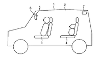
- FIG. 1 is a diagram showing an example of a vehicle 1 equipped with an electronic mirror device 5 according to Embodiment 1 of the present invention.
- a front seat (driver's seat and front passenger seat) 3 is disposed in front of the interior 2 of the vehicle 1, and a rear seat 4 is disposed behind.
- the electronic mirror device 5 is attached to the attachment position of the rearview mirror in front of the front seat 3 so that the attachment angle can be adjusted with respect to the attachment portion 6.
- An imaging unit 7 that captures the rear of the vehicle 1 is installed behind the rear seat 4.
- the electronic mirror device 5 can display a rear image of the vehicle 1 captured by the imaging unit 7.
- the electronic mirror device 5 performs wired communication or wireless communication with the imaging unit 7, and an image captured by the imaging unit 7 is transmitted from the imaging unit 7 to the electronic mirror device 5.
- FIG. 2 is a diagram showing an example of the configuration of the electronic mirror device 5 shown in FIG.
- the electronic mirror device 5 includes a main body case 51 having an opening on the front seat 3 side, and a display unit that is a liquid crystal display housed in the main body case 51 so that the display surface is on the front seat 3 side. 52 and a dimming filter 53 provided on the front seat 3 side of the display unit 52. Furthermore, the operation unit 54 that turns the display unit 52 on or off, the illuminance sensor 55 that detects the brightness of the interior 2 of the vehicle 1, and the temperature of the interior 2 of the vehicle 1 are detected.
- the temperature sensor 56, the storage unit 57 that stores various information such as the set value of the luminance of the backlight in the display unit 52 and the set value of the voltage applied to the dimming filter 53, the display unit 52, and the dimming filter 53 are controlled.
- a control unit 58 is provided.
- the dimming filter 53 is a device whose state is switched between a light reflection state that reflects light and a light transmission state that transmits light, depending on the state of energization. Such a dimming filter 53 is described in detail in, for example, Patent Document 2.
- Control unit 58 controls display unit 52 and dimming filter 53. Specifically, the control unit 58 causes the display unit 52 to display an image when the dimming filter 53 is in a light transmission state and in a transition period in which the light reflection state is switched to the light transmission state.
- this control will be described in more detail.
- the control unit 58 adjusts the voltage applied to the dimming filter 53 so that the dimming filter 53 has a reflectivity of 50% or more (preferably reflectivity). 80% or more). In this state, the dimming filter 53 serves as a mirror. As a result, the driver can confirm the rear from the image reflected on the light control filter 53.
- the control unit 58 adjusts the voltage applied to the dimming filter 53 to make the dimming filter 53 have a transmittance of 50% or more (preferably The light transmission state is 80% or higher. In this state, the dimming filter 53 transmits the video displayed on the display unit 52. At this time, the driver can confirm the rear from the rear image of the vehicle 1 displayed on the display unit 52.
- control unit 58 displays an image displayed on the display unit 52 when the dimming filter 53 is in a transition period in which the dimming filter 53 is switched from the light reflecting state to the light transmitting state than when the dimming filter 53 is in the light transmitting state. Executes the brightening control.
- the control unit 58 makes the backlight brightness of the display unit 52 brighter than when the dimming filter 53 is in a light transmission state. By controlling the backlight, the video displayed on the display unit 52 is brightened.
- control of the display unit 52 performed by the control unit 58 will be described in detail.
- FIG. 3 is a diagram illustrating an example of light reflectance and transition of light transmittance when the dimming filter 53 changes from a light reflection state to a light transmission state.
- the vertical axis of FIG. 3 indicates reflectance (%) or transmittance (%), and the horizontal axis indicates elapsed time (seconds) after the application of voltage to the light control filter 53 is stopped.
- This period is a transition period in which the dimming filter 53 is switched from the light reflection state to the light transmission state. Thereafter, the dimming filter 53 transitions to a light transmission state.
- the light reflectance graph and the light transmittance graph intersect at about 10 seconds. If the time exceeds this point, the influence of light reflection by the light control filter 53 on the visibility of the image becomes small, so the control unit 58 may continue the control to brighten the image until this point.
- the time point at which the light reflectance graph and the light transmittance graph intersect is approximately 10 seconds.
- the light reflectance graph and the light transmittance The point where the rate graph intersects may be shorter than 10 seconds.
- control unit 58 may continue the control to brighten the video until the point where the light reflectance graph and the light transmittance graph intersect.
- FIG. 4 is a diagram for explaining a method for controlling the luminance of the backlight.
- the vertical axis of FIG. 4 indicates the luminance (relative value) of the backlight, and the horizontal axis indicates the elapsed time (seconds) after the application of voltage to the light control filter 53 is stopped.
- the luminance after 20 seconds have elapsed since the application of voltage to the dimming filter 53 is stopped is set in advance as the luminance when the dimming filter 53 is in a light transmission state.
- control unit 58 sets the luminance of the backlight to, for example, 30 higher than the luminance set in advance as the luminance after the lapse of 20 seconds until 10 seconds have elapsed since the application of the voltage to the light control filter 53 was stopped.
- the backlight is controlled to be about%.
- the backlight illuminates the liquid crystal from the back side, so that the image displayed on the display unit 52 becomes brighter and the image is emphasized, so that the image becomes difficult to see due to the reflection of the light control filter 53. This can be prevented.
- control unit 58 performs control to brighten the video up to a predetermined time point, and then gradually changes the brightness of the video to a predetermined brightness when the dimming filter 53 is in a light transmission state.
- control unit 58 executes the control for increasing the luminance of the backlight until 10 seconds elapses, and then the backlight until the predetermined luminance after 20 seconds elapses. Reduce brightness gradually.
- control unit 58 finishes the control for increasing the luminance of the backlight based on the temperature inside the vehicle 2 (in the example of FIG. 4, the time point is 10 seconds after the application of the voltage is stopped). And the above control may be executed until that time. This is because the characteristics shown in FIG. 3 vary depending on the temperature inside the vehicle 2.
- the storage unit 57 stores information at the time when the control for increasing the luminance of the backlight is terminated in association with the temperature of the interior 2 of the vehicle 1. Then, the control unit 58 acquires information on the temperature detected by the temperature sensor 56, and reads out the information on the time point corresponding to the temperature from the storage unit 57.
- control unit 58 performs control to increase the luminance of the backlight until that time, and then gradually decreases the luminance of the backlight. Thereby, the time which performs the said control can be adjusted appropriately.
- control unit 58 may execute control to weaken the degree of brightening the image displayed on the display unit 52 as the brightness of the interior 2 of the vehicle 1 becomes darker.
- the brightness of the interior 2 of the vehicle 1 is detected by the illuminance sensor 55.
- FIG. 4 shows graphs A to D.
- the ratio of the luminance before 10 seconds to the luminance after 20 seconds has decreased.
- the luminance after the elapse of 20 seconds corresponds to the luminance when the dimming filter 53 is in the light transmission state
- the luminance before the elapse of 10 seconds switches the dimming filter 53 from the light reflection state to the light transmission state. This corresponds to the luminance in the transition period.
- the control unit 58 uses graphs A to B, graphs B to C, and graphs C to D for controlling the luminance of the backlight. Switch as follows.
- the image captured by the imaging unit 7 as well as the interior 2 of the vehicle 1 is dark, so the brightness of the backlight is increased.
- the image becomes unnaturally bright.
- control unit 58 controls the backlight so that the ratio described above decreases as the illuminance detected by the illuminance sensor 55 decreases. As a result, the image can be prevented from becoming unnaturally bright, and the power consumption can be reduced.
- control unit 58 brightens the video by controlling the backlight of the display unit 52.
- control unit 58 brightens the video by reducing the gamma value of the display unit 52. May be.
- the display unit 52 is not limited to a liquid crystal display, and may be another type of display such as an organic EL (Electro-Luminescence) display.
- organic EL Electro-Luminescence
- FIG. 5 is a diagram for explaining a gamma value control method.
- the vertical axis in FIG. 5 indicates the gamma value, and the horizontal axis indicates the elapsed time (seconds) after the application of the voltage to the light control filter 53 is stopped.
- the gamma value after 20 seconds have elapsed since the application of the voltage to the dimming filter 53 is stopped is set in advance as the gamma value when the dimming filter 53 is in the light transmission state. is there.
- this gamma value is 2.2.
- control unit 58 executes control to make the gamma value smaller than the previously set gamma value until 10 seconds have elapsed since the application of the voltage to the dimming filter 53 is stopped. In the example of FIG. 5, this gamma value is 1.5.
- the image displayed on the display unit 52 becomes brighter and the image is emphasized, so that it is possible to prevent the image from becoming difficult to see due to the influence of the reflection in the dimming filter 53.
- control unit 58 performs control to brighten the video up to a predetermined time point, and then gradually changes the brightness of the video to a predetermined brightness when the dimming filter 53 is in a light transmission state.
- control unit 58 executes the control for decreasing the gamma value until 10 seconds elapse, and then gradually increases the gamma value until the predetermined gamma value after 20 seconds elapses. Increase to.
- control unit 58 determines a time point for ending the control to reduce the gamma value based on the temperature in the interior 2 of the vehicle 1 (in the example of FIG. 5, 10 seconds after the voltage application is stopped). However, the above control may be executed until that time. This is because the characteristics shown in FIG. 3 vary depending on the temperature inside the vehicle 2.
- the storage unit 57 stores information at the time when the control for reducing the gamma value is terminated in association with the temperature of the interior 2 of the vehicle 1. Then, the control unit 58 acquires information on the temperature detected by the temperature sensor 56, and reads out the information on the time point corresponding to the temperature from the storage unit 57.
- control unit 58 executes control to decrease the gamma value until that point, and then gradually increases the gamma value. Thereby, the time which performs the said control can be adjusted appropriately.
- control unit 58 may execute control to weaken the degree of brightening the image displayed on the display unit 52 as the brightness of the interior 2 of the vehicle 1 becomes darker.
- the brightness of the interior 2 of the vehicle 1 is detected by the illuminance sensor 55.
- the gamma value before 10 seconds elapses in the order of graphs E, F, G, and H.
- the gamma value before the lapse of 10 seconds corresponds to the gamma value when the light control filter 53 is in a transition period in which the light reflection filter 53 switches from the light reflection state to the light transmission state.
- the controller 58 uses graphs E to F, graph F to G, and graph G to H as graphs used to control the gamma value. Switch.
- the image is reduced with a smaller gamma value.
- the image becomes unnaturally bright.
- the dimming filter 53 Even if the dimming filter 53 has not completely transitioned to the light transmission state, if the interior 2 of the vehicle 1 is dark, the influence of the reflected light from the dimming filter 53 on the appearance of the image is small. Therefore, the necessity for reducing the gamma value and enhancing the image is low.
- control unit 58 prevents the image from becoming unnaturally bright by executing the control to increase the gamma value as described above as the illuminance detected by the illuminance sensor 55 decreases. it can.
- the gamma value of the display unit 52 is decreased.
- the image may be brightened at least partially by increasing the contrast of the image.
- the display unit 52 is not limited to a liquid crystal display, and may be another type of display such as an organic EL (Electro-Luminescence) display.
- FIG. 6 is a diagram for explaining a contrast control method.
- the vertical axis in FIG. 6 indicates the video output value, and the horizontal axis indicates the video input value.
- the graph i is used until 10 seconds elapse after the voltage application to the dimming filter 53 is stopped, and the graph M is used after the voltage application to the dimming filter 53 is stopped. It is used after 20 seconds.
- the output value becomes the maximum value 255 in the region where the input value is large.
- the image displayed on the display unit 52 is brightened and the image is emphasized, so that it is possible to prevent the image from becoming difficult to see due to the influence of the reflection in the dimming filter 53.
- control unit 58 controls the display unit 52 to a predetermined time point, and then gradually changes the brightness of the image to the predetermined brightness when the dimming filter 53 is in the light transmission state.
- the control unit 58 performs correction to increase the contrast of the image using the graph i so that at least a part of the image becomes bright until 10 seconds elapse. From the time when the application of the voltage to the optical filter 53 is stopped until 20 seconds have passed and the graph M is used, the contrast of the image is corrected using the graph K and the graph L in order.
- control unit 58 determines a time point at which the control for increasing the contrast is finished based on the temperature of the interior 2 of the vehicle 1 (in the above-described example, 10 seconds after the voltage application is stopped), The above control may be executed until that time. This is because the characteristics shown in FIG. 3 vary depending on the temperature inside the vehicle 2.
- the storage unit 57 stores information at the time when the control for increasing the contrast is terminated in association with the temperature of the inside 2 of the vehicle 1. Then, the control unit 58 acquires information on the temperature detected by the temperature sensor 56, and reads out the information on the time point corresponding to the temperature from the storage unit 57.
- control unit 58 executes control to increase the contrast until that point, and then gradually decreases the contrast. Thereby, the time which performs the said control can be adjusted appropriately.
- control unit 58 may execute control to weaken the degree of brightening the image displayed on the display unit 52 as the brightness of the interior 2 of the vehicle 1 becomes darker.
- the brightness of the interior 2 of the vehicle 1 is detected by the illuminance sensor 55.
- the control unit 58 is used to correct the contrast of the image before 10 seconds have passed as the illuminance detected by the illuminance sensor 55 decreases.
- the graph is switched from graph i to graph K, from graph K to graph L, from graph L to graph M, and so on.
- the time zone is at night or when the vehicle 1 is traveling in a tunnel, not only the interior 2 of the vehicle 1 but also the image captured by the imaging unit 7 is dark, so the image is increased by increasing the contrast.
- the image is increased by increasing the contrast.
- control unit 58 can prevent the image from becoming unnaturally bright by executing the control to reduce the contrast as described above as the illuminance detected by the illuminance sensor 55 decreases. .
- the present invention is suitable for application to an electronic mirror device that displays images taken by an imaging unit mounted on a vehicle.
Landscapes
- Engineering & Computer Science (AREA)
- Physics & Mathematics (AREA)
- Mechanical Engineering (AREA)
- Multimedia (AREA)
- Nonlinear Science (AREA)
- General Physics & Mathematics (AREA)
- Crystallography & Structural Chemistry (AREA)
- Chemical & Material Sciences (AREA)
- Optics & Photonics (AREA)
- Computer Hardware Design (AREA)
- Theoretical Computer Science (AREA)
- Control Of Indicators Other Than Cathode Ray Tubes (AREA)
- Liquid Crystal Display Device Control (AREA)
- Liquid Crystal (AREA)
- Controls And Circuits For Display Device (AREA)
Abstract
調光フィルタが光反射状態から光透過状態に切り替わる過渡期にある場合であっても、調光フィルタの背面にある表示部に表示される映像が見えにくくなることを防止する。電子ミラー装置の表示部は、車両に搭載した撮像部が撮影した映像を表示し、調光フィルタは、表示部よりも運転席側に設けられ、通電の状態に応じて、光を反射する光反射状態と光を透過する光透過状態との間で状態が切り替わる。制御部は、表示部および調光フィルタを制御し、調光フィルタが光透過状態にある場合、および光反射状態から光透過状態に切り替わる過渡期にある場合に、表示部に映像を表示させ、調光フィルタが過渡期にある場合に、調光フィルタが光透過状態にある場合よりも表示部に表示される映像の少なくとも一部を明るくする制御を実行する。
Description
本発明は、車両に搭載された撮像部が撮像した映像などを表示する電子ミラー装置に関する。
従来、後続車の前照灯による眩しさを低減するため、反射率を減少させることが可能なエレクトロクロミック材料からなる調光フィルタが車両のミラーなどに利用されている。
このようなエレクトロクロミック技術の一例として、例えば特許文献1には、調光及び透明化の速度を向上させたエレクトロクロミックバックミラーが開示されている。
また、特許文献2には、通電状態に応じて光反射状態と光透過状態との間で状態が切り替わる調光フィルタが開示されている。
本発明は、調光フィルタが光反射状態から光透過状態に切り替わる過渡期にある場合であっても、調光フィルタの背面にある表示部に表示される映像が見えにくくなることを防止することが可能な電子ミラー装置を提供することを目的とする。
本発明の電子ミラー装置は、表示部と、調光フィルタと、制御部と、を有し、表示部は、車両に搭載した撮像部が撮影した映像を表示可能である。調光フィルタは、表示部よりも運転席側に設けられ、通電の状態に応じて、光を反射する光反射状態と光を透過する光透過状態との間で状態を切り替える。制御部は、表示部および調光フィルタを制御する。制御部は、調光フィルタが光透過状態にある場合、および光反射状態から光透過状態に切り替わる過渡期にある場合に、表示部に映像を表示させ、調光フィルタが過渡期にある場合に、調光フィルタが光透過状態にある場合よりも表示部に表示される映像の少なくとも一部を明るくする制御を実行する。
本発明によれば、調光フィルタが光反射状態から光透過状態に切り替わる過渡期にある場合であっても、調光フィルタの背面にある表示部に表示される映像が見えにくくなることを防止することができる。
本発明の実施の形態の説明に先立ち、従来の装置における問題点を簡単に説明する。エレクトロクロミック材料が透明になる速度を向上させたとしても、現時点ではエレクトロクロミック材料を瞬時に透明に変えることができる技術は開発されていない。
そのため、エレクトロクロミック材料の背面にあるものを見たい場合であっても、エレクトロクロミック材料が透明になるまでの間は、エレクトロクロミック材料により反射される反射光とエレクトロクロミック材料の背面からの透過光とが存在することになり、エレクトロクロミック材料の背面にあるものが見えにくくなる。
以下に、本発明の実施の形態について、図面を参照して詳細に説明する。なお、以下に説明する実施の形態は一例であり、本発明はこれらの実施の形態により限定されるものではない。
(実施の形態1)
図1は、本発明の実施の形態1に係る電子ミラー装置5を搭載した車両1の一例を示す図である。車両1の内部2の前方には前席(運転席と助手席)3が配置され、後方には後席4が配置されている。
図1は、本発明の実施の形態1に係る電子ミラー装置5を搭載した車両1の一例を示す図である。車両1の内部2の前方には前席(運転席と助手席)3が配置され、後方には後席4が配置されている。
さらに、前席3の前方のルームミラーの取り付け位置には、取付部6に対して取付角度を調整可能に電子ミラー装置5が取り付けられている。また、後席4の後方には、車両1の後方を撮像する撮像部7が設置されている。
ここで、電子ミラー装置5は、撮像部7で撮像された車両1の後方画像などを表示することができる。なお、電子ミラー装置5は、撮像部7との間で、有線通信、または、無線通信を行い、撮像部7により撮像された映像が撮像部7から電子ミラー装置5に送信される。
図2は、図1に示した電子ミラー装置5の構成の一例を示す図である。
図2に示すように、電子ミラー装置5は、前席3側に開口部を有する本体ケース51、本体ケース51に表示面が前席3側となるように収容された液晶ディスプレイである表示部52、表示部52の前席3側に設けられた調光フィルタ53を有している。さらに、表示部52をオン(ON)状態、または、オフ(OFF)状態にする操作部54、車両1の内部2の明るさを検出する照度センサ55、車両1の内部2の温度を検出する温度センサ56、表示部52におけるバックライトの輝度の設定値や調光フィルタ53に印加する電圧の設定値などの種々の情報を記憶する記憶部57、表示部52および調光フィルタ53を制御する制御部58を有している。
調光フィルタ53は、通電の状態に応じて、光を反射する光反射状態と光を透過する光透過状態との間で状態が切り替わるデバイスである。このような調光フィルタ53は、例えば特許文献2等に詳細に記載されている。
制御部58は、表示部52および調光フィルタ53を制御する。具体的には、制御部58は、調光フィルタ53が光透過状態にある場合、および光反射状態から光透過状態に切り替わる過渡期にある場合に、表示部52に映像を表示させる。以下では、この制御についてさらに詳しく説明する。
制御部58は、操作部54の操作によって表示部52がOFF状態にされると、調光フィルタ53に印加する電圧を調整して、調光フィルタ53を反射率50%以上(好ましくは反射率80%以上)の光反射状態にする。この状態では、調光フィルタ53は、ミラーとしての役割を果たす。これにより、運転手は、調光フィルタ53に映った像により後方を確認することができる。
一方、操作部54の操作によって表示部52がON状態にされると、制御部58は、調光フィルタ53に印加する電圧を調整して、調光フィルタ53を透過率50%以上(好ましくは透過率80%以上)の光透過状態にする。この状態では、調光フィルタ53は、表示部52に表示された映像を透過する。このとき、運転手は、表示部52に表示された車両1の後方画像により後方を確認することができる。
また、制御部58は、調光フィルタ53が光反射状態から光透過状態に切り替わる過渡期にある場合に、調光フィルタ53が光透過状態にある場合よりも表示部52に表示される映像を明るくする制御を実行する。
具体的には、制御部58は、調光フィルタ53が上述した過渡期にある場合に、調光フィルタ53が光透過状態にある場合よりも、表示部52のバックライトの明るさが明るくなるようバックライトを制御することにより、表示部52に表示される映像を明るくする。
ここで、制御部58が行う表示部52の制御について詳しく説明する。
図3は、調光フィルタ53が光反射状態から光透過状態へと変化する場合の光反射率、および、光透過率の推移の一例を示す図である。図3の縦軸は反射率(%)、または、透過率(%)を示し、横軸は調光フィルタ53に対する電圧の印加を停止してからの経過時間(秒)を示している。
図3に示すように、調光フィルタ53に対する電圧の印加が停止されると、光透過率が増加し、光反射率が減少する。この期間は、調光フィルタ53が光反射状態から光透過状態に切り替わる過渡期である。その後、調光フィルタ53は光透過状態へと遷移する。
ここで、光反射率のグラフと光透過率のグラフとは、略10秒の時点で交差する。この時点を超えると、調光フィルタ53による光の反射が映像の見易さに及ぼす影響は小さくなるので、制御部58は、この時点まで映像を明るくする制御を継続すればよい。
また、ここでは、光反射率のグラフと光透過率のグラフとが交差する時点が略10秒の時点であることとしたが、調光フィルタ53の種類によっては光反射率のグラフと光透過率のグラフとが交差する時点が10秒よりも短くなる場合もある。
この場合も、制御部58は、光反射率のグラフと光透過率のグラフとが交差する時点まで、映像を明るくする制御を継続すればよい。
図4は、バックライトの輝度の制御方法について説明する図である。図4の縦軸はバックライトの輝度(相対値)を示し、横軸は調光フィルタ53に対する電圧の印加を停止してからの経過時間(秒)を示している。
例えば、グラフAにおいて、調光フィルタ53に対する電圧の印加を停止してから20秒経過した後の輝度は、調光フィルタ53が光透過状態にある場合の輝度として予め設定されたものである。
この場合、制御部58は、調光フィルタ53に対する電圧の印加を停止してから10秒経過するまで、バックライトの輝度が、20秒経過後の輝度として予め設定された輝度よりも、例えば30%程度大きくなるようバックライトを制御する。
これにより、バックライトが背面側から液晶を照らすことになるので、表示部52に表示される映像が明るくなり、映像が強調されるので、調光フィルタ53における反射の影響により映像が見えにくくなることを防止することができる。
さらに、制御部58は、映像を明るくする制御を所定の時点まで行った後、映像の明るさを調光フィルタ53が光透過状態にある場合の所定の明るさまで徐々に変化させる。
具体的には、制御部58は、図4におけるグラフAにおいて、バックライトの輝度を大きくする制御を10秒を経過するまで実行した後、20秒経過後の所定の輝度になるまでバックライトの輝度を徐々に低下させる。
これにより、急激な映像の明るさの変化により、運転手が違和感を覚えることを防止することができる。
また、制御部58は、車両1の内部2の温度に基づいて、バックライトの輝度を大きくする制御を終了する時点(図4の例では、電圧の印加を停止してから10秒の時点)を決定し、その時点まで上記制御を実行することとしてもよい。これは、図3に示した特性が車両1の内部2の温度により変化するためである。
この場合、例えば、記憶部57は、車両1の内部2の温度と対応付けて、バックライトの輝度を大きくする制御を終了する時点の情報を記憶しておく。そして、制御部58は、温度センサ56により検出された温度の情報を取得し、その温度に対応する上記時点の情報を記憶部57から読み出す。
そして、制御部58は、その時点までバックライトの輝度を大きくする制御を実行し、その後バックライトの輝度を徐々に低下させる。これにより、上記制御を行う時間を適切に調整することができる。
さらに、制御部58は、車両1の内部2の明るさが暗くなるにつれ、表示部52に表示される映像を明るくする度合いを弱める制御を実行することとしてもよい。ここで、車両1の内部2の明るさは、照度センサ55により検出される。
例えば、図4には、グラフA~Dが示されているが、グラフA、B、C、Dの順に、20秒経過後の輝度に対する10秒経過前の輝度の比が小さくなっている。ここで、20秒経過後の輝度は、調光フィルタ53が光透過状態にある場合の輝度に相当し、10秒経過前の輝度は、調光フィルタ53が光反射状態から光透過状態に切り替わる過渡期にある場合の輝度に相当する。
この場合、制御部58は、照度センサ55により検出された照度が小さくなるにつれ、バックライトの輝度の制御に用いるグラフを、グラフAからグラフB、グラフBからグラフC、グラフCからグラフDというように切り替える。
例えば、時間帯が夜間である場合や、車両1がトンネル内を走行している場合、車両1の内部2だけでなく撮像部7により撮像される映像も暗いので、バックライトの輝度を大きくして映像を強調すると、映像が不自然に明るくなってしまう。
また、調光フィルタ53が光透過状態に完全に遷移していない場合であっても、車両1の内部2が暗い場合、調光フィルタ53からの反射光が映像の見え方に与える影響は小さいので、バックライトの輝度を大きくして映像を強調する必要性も低い。
このようなことから、制御部58は、照度センサ55により検出された照度が小さくなるにつれ、上述した比が小さくなるようバックライトを制御する。これにより、映像が不自然に明るくなることを防止でき、さらには消費電力を低減することもできる。
(実施の形態2)
上述した実施の形態1では、制御部58は、表示部52のバックライトを制御することにより映像を明るくするようにしたが、表示部52のガンマ値を小さくすることにより映像を明るくするようにしてもよい。
上述した実施の形態1では、制御部58は、表示部52のバックライトを制御することにより映像を明るくするようにしたが、表示部52のガンマ値を小さくすることにより映像を明るくするようにしてもよい。
本実施の形態では、制御部58が、表示部52のガンマ値を小さくする場合について説明する。ここで、表示部52は、液晶ディスプレイに限定されず、有機EL(Electro-Luminescence)ディスプレイなどの他の種類のディスプレイであってもよい。
図5は、ガンマ値の制御方法について説明する図である。図5の縦軸はガンマ値を示し、横軸は調光フィルタ53に対する電圧の印加を停止してからの経過時間(秒)を示している。
例えば、グラフEにおいて、調光フィルタ53に対する電圧の印加を停止してから20秒経過した後のガンマ値は、調光フィルタ53が光透過状態にある場合のガンマ値として予め設定されたものである。図5の例では、このガンマ値は、2.2である。
この場合、制御部58は、調光フィルタ53に対する電圧の印加を停止してから10秒経過するまで、予め設定された上記ガンマ値よりも、ガンマ値を小さくする制御を実行する。図5の例では、このガンマ値は、1.5である。
これにより、表示部52に表示される映像が明るくなり、映像が強調されるので、調光フィルタ53における反射の影響により映像が見えにくくなることを防止することができる。
さらに、制御部58は、映像を明るくする制御を所定の時点まで行った後、映像の明るさを調光フィルタ53が光透過状態にある場合の所定の明るさまで徐々に変化させる。
具体的には、制御部58は、図5におけるグラフEにおいて、ガンマ値を小さくする制御を10秒を経過するまで実行した後、20秒経過後の所定のガンマ値になるまでガンマ値を徐々に増加させる。
これにより、急激な映像の明るさの変化により、運転手が違和感を覚えることを防止することができる。
また、制御部58は、車両1の内部2の温度に基づいて、ガンマ値を小さくする制御を終了する時点(図5の例では、電圧の印加を停止してから10秒の時点)を決定し、その時点まで上記制御を実行することとしてもよい。これは、図3に示した特性が車両1の内部2の温度により変化するためである。
この場合、例えば、記憶部57は、車両1の内部2の温度と対応付けて、ガンマ値を小さくする制御を終了する時点の情報を記憶しておく。そして、制御部58は、温度センサ56により検出された温度の情報を取得し、その温度に対応する上記時点の情報を記憶部57から読み出す。
そして、制御部58は、その時点までガンマ値を小さくする制御を実行し、その後ガンマ値を徐々に増加させる。これにより、上記制御を行う時間を適切に調整することができる。
さらに、制御部58は、車両1の内部2の明るさが暗くなるにつれ、表示部52に表示される映像を明るくする度合いを弱める制御を実行することとしてもよい。ここで、車両1の内部2の明るさは、照度センサ55により検出される。
例えば、図5には、グラフE~Hが示されているが、グラフE、F、G、Hの順に、10秒経過前のガンマ値が大きくなっている。ここで、10秒経過前のガンマ値は、調光フィルタ53が光反射状態から光透過状態に切り替わる過渡期にある場合のガンマ値に相当する。
この場合、制御部58は、照度センサ55により検出された照度が小さくなるにつれ、ガンマ値の制御に用いるグラフを、グラフEからグラフF、グラフFからグラフG、グラフGからグラフHというように切り替える。
例えば、時間帯が夜間である場合や、車両1がトンネル内を走行している場合、車両1の内部2だけでなく撮像部7により撮像される映像も暗いので、ガンマ値を小さくして映像を強調すると、映像が不自然に明るくなってしまう。
また、調光フィルタ53が光透過状態に完全に遷移していない場合であっても、車両1の内部2が暗い場合、調光フィルタ53からの反射光が映像の見え方に与える影響は小さいので、ガンマ値を小さくして映像を強調する必要性も低い。
このようなことから、制御部58は、照度センサ55により検出された照度が小さくなるにつれ、上述したようにガンマ値を大きくする制御を実行することにより、映像が不自然に明るくなることを防止できる。
(実施の形態3)
上述した実施の形態2では、表示部52のガンマ値を小さくすることとしたが、映像のコントラストを大きくすることにより映像が少なくとも一部において明るくなるようにしてもよい。
上述した実施の形態2では、表示部52のガンマ値を小さくすることとしたが、映像のコントラストを大きくすることにより映像が少なくとも一部において明るくなるようにしてもよい。
本実施の形態では、映像のコントラストを大きくする場合について説明する。ここで、表示部52は、液晶ディスプレイに限定されず、有機EL(Electro-Luminescence)ディスプレイなどの他の種類のディスプレイであってもよい。
図6は、コントラストの制御方法について説明する図である。図6の縦軸は映像の出力値を示し、横軸は映像の入力値を示している。
例えば、グラフiは、調光フィルタ53に対する電圧の印加を停止してから10秒経過するまでの間に用いられるものであり、グラフMは、調光フィルタ53に対する電圧の印加を停止してから20秒経過した後に用いられるものである。
調光フィルタ53に対する電圧の印加を停止してから10秒経過するまでの間、グラフiがグラフMの代わりに用いられると、入力値が大きい領域において、出力値が最大値の255となる。
これにより、表示部52に表示される映像の少なくとも一部が明るくなり、映像が強調されるので、調光フィルタ53における反射の影響により映像が見えにくくなることを防止することができる。
さらに、制御部58は、表示部52に対する制御を所定の時点まで行った後、映像の明るさを調光フィルタ53が光透過状態にある場合の所定の明るさまで徐々に変化させる。
具体的には、制御部58は、図6におけるグラフi~Mにおいて、10秒を経過するまで映像の少なくとも一部が明るくなるようグラフiを用いて映像のコントラストを大きくする補正をし、調光フィルタ53に対する電圧の印加を停止してから20秒経過してグラフMが用いられるまでの間、グラフK、および、グラフLを順に用いて映像のコントラストを補正する。
これにより、急激な映像の明るさの変化により、運転手が違和感を覚えることを防止することができる。
また、制御部58は、車両1の内部2の温度に基づいて、コントラストを大きくする制御を終了する時点(上述した例では、電圧の印加を停止してから10秒の時点)を決定し、その時点まで上記制御を実行することとしてもよい。これは、図3に示した特性が車両1の内部2の温度により変化するためである。
この場合、例えば、記憶部57は、車両1の内部2の温度と対応付けて、コントラストを大きくする制御を終了する時点の情報を記憶しておく。そして、制御部58は、温度センサ56により検出された温度の情報を取得し、その温度に対応する上記時点の情報を記憶部57から読み出す。
そして、制御部58は、その時点までコントラストを大きくする制御を実行し、その後コントラストを徐々に小さくする。これにより、上記制御を行う時間を適切に調整することができる。
さらに、制御部58は、車両1の内部2の明るさが暗くなるにつれ、表示部52に表示される映像を明るくする度合いを弱める制御を実行することとしてもよい。ここで、車両1の内部2の明るさは、照度センサ55により検出される。
例えば、図6には、グラフi~Mが示されているが、制御部58は、照度センサ55により検出された照度が小さくなるにつれ、10秒を経過する前の映像のコントラストの補正に用いるグラフを、グラフiからグラフK、グラフKからグラフL、グラフLからグラフMというように切り替える。
例えば、時間帯が夜間である場合や、車両1がトンネル内を走行している場合、車両1の内部2だけでなく撮像部7により撮像される映像も暗いので、コントラストを大きくして映像を強調すると、映像が不自然に明るくなる部分が生じる。
また、調光フィルタ53が光透過状態に完全に遷移していない場合であっても、車両1の内部2が暗い場合、調光フィルタ53からの反射光が映像の見え方に与える影響は小さいので、コントラストを大きくして映像を強調する必要性も低い。
このようなことから、制御部58は、照度センサ55により検出された照度が小さくなるにつれ、上述したようにコントラストを小さくする制御を実行することにより、映像が不自然に明るくなることを防止できる。
本発明は、車両に搭載した撮像部が撮影した映像などを表示する電子ミラー装置に適用するのに好適である。
1 車両
2 内部
3 前席
4 後席
5 電子ミラー装置
6 取付部
7 撮像部
51 本体ケース
52 表示部
53 調光フィルタ
54 操作部
55 照度センサ
56 温度センサ
57 記憶部
58 制御部
2 内部
3 前席
4 後席
5 電子ミラー装置
6 取付部
7 撮像部
51 本体ケース
52 表示部
53 調光フィルタ
54 操作部
55 照度センサ
56 温度センサ
57 記憶部
58 制御部
Claims (9)
- 車両に搭載した撮像部が撮影した映像を表示する表示部と、
前記表示部よりも運転席側に設けられ、通電の状態に応じて、光を反射する光反射状態と光を透過する光透過状態との間で状態が切り替わる調光フィルタと、
前記表示部および前記調光フィルタを制御する制御部と、を備え、
前記制御部は、
前記調光フィルタが前記光透過状態にある場合、および前記光反射状態から前記光透過状態に切り替わる過渡期にある場合に、前記表示部に前記映像を表示させ、
前記調光フィルタが前記過渡期にある場合に、前記調光フィルタが前記光透過状態にある場合よりも前記表示部に表示される映像の少なくとも一部を明るくする制御を実行する、電子ミラー装置。 - 前記制御部は、前記制御を所定の時点まで行った後、前記映像の少なくとも一部の明るさを、前記調光フィルタが前記光透過状態にある場合の所定の明るさになるまで徐々に変化させる請求項1に記載の電子ミラー装置。
- 前記所定の時点は、前記調光フィルタの反射率と透過率とが略同一となる時点である請求項2に記載の電子ミラー装置。
- 前記所定の時点は、前記過渡期の開始時から10秒以下の時点である請求項2に記載の電子ミラー装置。
- 前記制御部は、車室内の温度に基づいて前記制御を終了する時点を決定し、該時点まで前記制御を実行する請求項1に記載の電子ミラー装置。
- 前記表示部は、液晶ディスプレイであり、前記表示部の背面側から液晶を照らすバックライトを備え、
前記制御部は、前記調光フィルタが前記過渡期にある場合に、前記調光フィルタが前記光透過状態にある場合よりも前記バックライトの輝度を高くすることにより前記制御を実行する請求項1に記載の電子ミラー装置。 - 前記制御部は、前記調光フィルタが前記過渡期にある場合に、前記調光フィルタが前記光透過状態にある場合よりも前記表示部におけるガンマ値を小さくすることにより前記制御を実行する請求項1に記載の電子ミラー装置。
- 前記制御部は、前記調光フィルタが前記過渡期にある場合に、前記調光フィルタが前記光透過状態にある場合よりも前記映像のコントラストを増大させることにより前記制御を実行する請求項1に記載の電子ミラー装置。
- 前記制御部は、車室内の明るさが暗くなるにつれ、前記映像の少なくとも一部を明るくする度合いを弱める制御を実行する請求項1に記載の電子ミラー装置。
Priority Applications (3)
| Application Number | Priority Date | Filing Date | Title |
|---|---|---|---|
| EP16771661.2A EP3260328A4 (en) | 2015-03-31 | 2016-03-14 | Electron mirror apparatus |
| US15/555,996 US10391942B2 (en) | 2015-03-31 | 2016-03-14 | Electronic mirror apparatus |
| CN201680018484.XA CN107406036B (zh) | 2015-03-31 | 2016-03-14 | 电子镜装置 |
Applications Claiming Priority (2)
| Application Number | Priority Date | Filing Date | Title |
|---|---|---|---|
| JP2015070857A JP6464479B2 (ja) | 2015-03-31 | 2015-03-31 | 電子ミラー装置 |
| JP2015-070857 | 2015-03-31 |
Publications (1)
| Publication Number | Publication Date |
|---|---|
| WO2016157767A1 true WO2016157767A1 (ja) | 2016-10-06 |
Family
ID=57004092
Family Applications (1)
| Application Number | Title | Priority Date | Filing Date |
|---|---|---|---|
| PCT/JP2016/001424 Ceased WO2016157767A1 (ja) | 2015-03-31 | 2016-03-14 | 電子ミラー装置 |
Country Status (5)
| Country | Link |
|---|---|
| US (1) | US10391942B2 (ja) |
| EP (1) | EP3260328A4 (ja) |
| JP (1) | JP6464479B2 (ja) |
| CN (1) | CN107406036B (ja) |
| WO (1) | WO2016157767A1 (ja) |
Families Citing this family (2)
| Publication number | Priority date | Publication date | Assignee | Title |
|---|---|---|---|---|
| WO2018096953A1 (ja) * | 2016-11-22 | 2018-05-31 | ソニー株式会社 | 撮像装置、表示システムおよび方法 |
| JP7113685B2 (ja) * | 2018-07-10 | 2022-08-05 | 株式会社村上開明堂 | ミラー表示装置およびその制御方法 |
Citations (4)
| Publication number | Priority date | Publication date | Assignee | Title |
|---|---|---|---|---|
| JPH07266928A (ja) * | 1994-03-29 | 1995-10-17 | Araco Corp | 後写鏡 |
| JP2004294647A (ja) * | 2003-03-26 | 2004-10-21 | Sharp Corp | 表示素子 |
| JP2012006593A (ja) * | 2000-11-06 | 2012-01-12 | Semiconductor Energy Lab Co Ltd | 車両 |
| JP2015516917A (ja) * | 2012-04-24 | 2015-06-18 | ジェンテックス コーポレイション | 表示ミラー組立品 |
Family Cites Families (5)
| Publication number | Priority date | Publication date | Assignee | Title |
|---|---|---|---|---|
| US5883605A (en) * | 1992-02-25 | 1999-03-16 | Gentex Corporation | Automatic electrochromic control of light level of vacuum fluorescent display |
| US5285060A (en) | 1992-12-15 | 1994-02-08 | Donnelly Corporation | Display for automatic rearview mirror |
| JP4979376B2 (ja) | 2003-05-06 | 2012-07-18 | ジェンテックス コーポレイション | 車両用バックミラー要素及びこれらの要素を組み込むアセンブリ |
| US9487144B2 (en) * | 2008-10-16 | 2016-11-08 | Magna Mirrors Of America, Inc. | Interior mirror assembly with display |
| JP2012181389A (ja) | 2011-03-02 | 2012-09-20 | Chiba Univ | 表示装置 |
-
2015
- 2015-03-31 JP JP2015070857A patent/JP6464479B2/ja not_active Expired - Fee Related
-
2016
- 2016-03-14 EP EP16771661.2A patent/EP3260328A4/en not_active Withdrawn
- 2016-03-14 US US15/555,996 patent/US10391942B2/en active Active
- 2016-03-14 WO PCT/JP2016/001424 patent/WO2016157767A1/ja not_active Ceased
- 2016-03-14 CN CN201680018484.XA patent/CN107406036B/zh active Active
Patent Citations (4)
| Publication number | Priority date | Publication date | Assignee | Title |
|---|---|---|---|---|
| JPH07266928A (ja) * | 1994-03-29 | 1995-10-17 | Araco Corp | 後写鏡 |
| JP2012006593A (ja) * | 2000-11-06 | 2012-01-12 | Semiconductor Energy Lab Co Ltd | 車両 |
| JP2004294647A (ja) * | 2003-03-26 | 2004-10-21 | Sharp Corp | 表示素子 |
| JP2015516917A (ja) * | 2012-04-24 | 2015-06-18 | ジェンテックス コーポレイション | 表示ミラー組立品 |
Non-Patent Citations (1)
| Title |
|---|
| See also references of EP3260328A4 * |
Also Published As
| Publication number | Publication date |
|---|---|
| CN107406036B (zh) | 2019-10-15 |
| JP2016190535A (ja) | 2016-11-10 |
| EP3260328A4 (en) | 2018-03-14 |
| US20180056876A1 (en) | 2018-03-01 |
| EP3260328A1 (en) | 2017-12-27 |
| CN107406036A (zh) | 2017-11-28 |
| US10391942B2 (en) | 2019-08-27 |
| JP6464479B2 (ja) | 2019-02-06 |
Similar Documents
| Publication | Publication Date | Title |
|---|---|---|
| JP5056831B2 (ja) | ヘッドアップディスプレイ装置 | |
| US10325550B2 (en) | Electronic mirror device | |
| JP4829991B2 (ja) | 自動調光システム | |
| US20170120829A1 (en) | Electronic mirror device and electronic mirror system using same | |
| WO2016006182A1 (ja) | 車両用表示装置 | |
| WO2013063903A1 (zh) | 一种多功能汽车后视镜 | |
| JP2010091816A (ja) | 表示装置 | |
| JP2901489B2 (ja) | 後写鏡 | |
| US20130286177A1 (en) | Localized glass glare reduction | |
| JP6464479B2 (ja) | 電子ミラー装置 | |
| WO2022116663A1 (zh) | 显示器背光亮度的调整方法和装置 | |
| US10444498B2 (en) | Waveguide mirror display system | |
| JP2019001293A (ja) | 車載用表示装置 | |
| JP2017047804A (ja) | ミラー装置及びその制御方法 | |
| JP2005343332A (ja) | 車載用dvdシステム | |
| US11485287B2 (en) | Electronic mirror system | |
| JP2007125963A (ja) | 自動防眩装置 | |
| JP2009073336A (ja) | 車両用表示装置 | |
| JP7294169B2 (ja) | 表示装置 | |
| KR20050120022A (ko) | 인사이드 미러용 표시창의 조도 조절 장치 | |
| JP2021113010A (ja) | 画像表示装置 | |
| WO2013094012A1 (ja) | ヘッドアップディスプレイ、表示装置、及び制御方法 | |
| JP2020045043A (ja) | 車両用ミラー | |
| WO2025133808A1 (en) | System and method for estimating natural daylight using an image sensor | |
| JP2025116573A (ja) | 照明制御システム |
Legal Events
| Date | Code | Title | Description |
|---|---|---|---|
| 121 | Ep: the epo has been informed by wipo that ep was designated in this application |
Ref document number: 16771661 Country of ref document: EP Kind code of ref document: A1 |
|
| WWE | Wipo information: entry into national phase |
Ref document number: 15555996 Country of ref document: US |
|
| REEP | Request for entry into the european phase |
Ref document number: 2016771661 Country of ref document: EP |
|
| NENP | Non-entry into the national phase |
Ref country code: DE |