WO2016158024A1 - Gantry crane and crane facility - Google Patents
Gantry crane and crane facility Download PDFInfo
- Publication number
- WO2016158024A1 WO2016158024A1 PCT/JP2016/054007 JP2016054007W WO2016158024A1 WO 2016158024 A1 WO2016158024 A1 WO 2016158024A1 JP 2016054007 W JP2016054007 W JP 2016054007W WO 2016158024 A1 WO2016158024 A1 WO 2016158024A1
- Authority
- WO
- WIPO (PCT)
- Prior art keywords
- crane
- trolley
- girder
- rear direction
- gantry
- Prior art date
- Legal status (The legal status is an assumption and is not a legal conclusion. Google has not performed a legal analysis and makes no representation as to the accuracy of the status listed.)
- Ceased
Links
Images



Classifications
-
- B—PERFORMING OPERATIONS; TRANSPORTING
- B66—HOISTING; LIFTING; HAULING
- B66C—CRANES; LOAD-ENGAGING ELEMENTS OR DEVICES FOR CRANES, CAPSTANS, WINCHES, OR TACKLES
- B66C13/00—Other constructional features or details
- B66C13/52—Details of compartments for driving engines or motors or of operator's stands or cabins
- B66C13/54—Operator's stands or cabins
-
- B—PERFORMING OPERATIONS; TRANSPORTING
- B66—HOISTING; LIFTING; HAULING
- B66C—CRANES; LOAD-ENGAGING ELEMENTS OR DEVICES FOR CRANES, CAPSTANS, WINCHES, OR TACKLES
- B66C19/00—Cranes comprising trolleys or crabs running on fixed or movable bridges or gantries
Definitions
- the present invention relates to a gantry crane and crane equipment.
- a portal crane a structure in which a portal structure is constituted by a pair of legs arranged in the left-right direction and a girder spanned between the legs is known.
- the portal structure can be moved in the front-rear direction, and the trolley is arranged on the upper surface of the girder so that the trolley can traverse, and the lifting / lowering work is performed using a lifting tool that can be moved up and down on the trolley. .
- a driver's cab for performing operations such as the above is generally connected to a trolley capable of traversing the upper surface of the girder via a passage portion.
- the passage portion connects the cab and the trolley so as to be able to go back and forth, and an inclined passage that is inclined obliquely downward from an end portion in the front-rear direction of the trolley is a general configuration (see Patent Document 1). (See FIG. 12).
- each gantry crane can travel in the front-rear direction, for example, in order to prepare for strong winds such as typhoons, the cranes are connected as close as possible in the front-rear direction There is. In this case, there is a limit to the proximity of adjacent driver's cabs.
- the present invention has been made to solve such problems, and an object of the present invention is to provide a gantry crane and crane equipment that can approach a structure such as an adjacent gantry crane as compared with the prior art.
- a gantry crane includes a pair of legs arranged in the left-right direction and capable of traveling in the front-rear direction, a girder spanned between the legs, a trolley capable of traversing along the girder, and a crane operation
- a gantry crane provided with a cab for performing the operation and a passage portion connected to the trolley and connecting the trolley and the cab, the passage portion has at least a portion extending straight in the vertical direction.
- the portion extending straight at least in the vertical direction of the passage portion is longer in the front-rear direction from the girder of the cab than in the case of the passage portion that is inclined downward as in the prior art.
- the amount of protrusion is reduced.
- the gantry crane can be closer to the adjacent structure than the prior art.
- the passage portion extends straight in the vertical direction over the entire region from the upper end to the lower end, the amount of protrusion in the front-rear direction from the girder of the cab is further reduced, and further to the adjacent structure. Can be close.
- the portion of the passage portion that extends straight in the vertical direction may include a spiral staircase extending in the vertical direction.
- a spiral staircase extending in the vertical direction.
- the crane equipment according to one aspect of the present invention is characterized in that a plurality of the gantry cranes are arranged in the front-rear direction.
- the gantry crane can be brought closer to the adjacent gantry crane than the prior art.
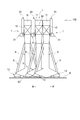
- FIG. 1 is a perspective view showing a crane facility including a gantry crane according to a first embodiment of the present invention from the front side.
- FIG. 2 is a front view of FIG.
- FIG. 3 is a left side view of FIG.
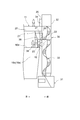
- FIG. 4 is an enlarged schematic configuration diagram showing the driver's cab, the passage portion, and the vicinity thereof in FIG.
- FIG. 5 is a right side view of FIG.
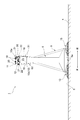
- FIG. 6 is a schematic side view showing crane equipment provided with a gantry crane according to a second embodiment of the present invention.
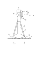
- FIG. 7 is a schematic side view showing crane equipment provided with a gantry crane according to a third embodiment of the present invention.
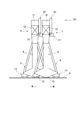
- FIG. 8 is a schematic side view showing crane equipment including a gantry crane according to the fourth embodiment of the present invention.
- FIG. 1 is a perspective view showing a crane facility including a gantry crane according to a first embodiment of the present invention from the front side
- FIG. 2 is a front view of FIG. 1
- FIG. 1 is a perspective view showing a crane facility including a gantry crane according to a first embodiment of the present invention from the front side
- FIG. 2 is a front view of FIG. 1
- a crane facility 100 is employed in a dock at a shipyard, and a gantry crane 1 that can travel along quays 4 and 5 with a dock 3 interposed therebetween.
- the gantry crane 1 is a huge portal crane that can run on rails, and is also called a Goliath crane.
- rails 6 and 7 are laid along the quays 4 and 5, respectively. These rails 6 and 7 are tracks for running the gantry crane 1.
- the gantry crane 1 includes a pair of leg portions 8 and 9 disposed on the quays 4 and 5, and a girder 10 spanned between the pair of leg portions 8 and 9, respectively. , And a main trolley (trolley) 11 and a supplementary trolley 12 that are movable along the girder 10.
- the direction in which the rails 6 and 7 extend and the direction in which the gantry crane 1 travels is referred to as the front-rear direction
- the direction in which the girder 10 extends is perpendicular to the front-rear direction and the trolleys 11 and 12 are traversed.
- the direction that becomes the direction is called the left-right direction.
- the pair of leg portions 8 and 9 are provided corresponding to the rails 6 and 7, respectively, and have different rigidity.
- the leg 8 functions as a rigid leg having higher rigidity than the leg 9, and the leg 9 functions as a swing leg having lower rigidity than the leg 8.
- Traveling devices 13 for traveling along the rails 6 and 7 are provided at the lower end portions 8a and 9a of the leg portions 8 and 9, respectively.
- Two traveling devices 13 are provided at the front and rear of the leg portions 8 and 9, and one traveling device 13 is provided with, for example, 16 wheels.
- the quantities of the traveling device 13 and the wheels are not particularly limited, and other quantities may be used.
- the gantry crane 1 can travel in the front-rear direction by the travel device 13 moving on the rails 6 and 7.
- the girder 10 has a substantially trapezoidal section, a double box type in which beams 10a (see FIG. 4) and 10b extending in the left-right direction are juxtaposed in the front-rear direction, and the left and right end portions are connected by connecting portions 10c and 10d.
- the girder has a substantially trapezoidal section, a double box type in which beams 10a (see FIG. 4) and 10b extending in the left-right direction are juxtaposed in the front-rear direction, and the left and right end portions are connected by connecting portions 10c and 10d.
- main trolley rails 16 are provided on the outer edges in the front-rear direction of the upper end surfaces of the beams 10a and 10b of the girder 10, respectively.
- Supplementary trolley rails 17 are provided on the inner edges in the front-rear direction of the upper end surfaces of the beams 10a and 10b, respectively.
- the main trolley rail 16 is a track for traversing the main trolley 11
- the auxiliary trolley rail 17 is a track for traversing the auxiliary trolley 12.
- the main trolley 11 lifts or suspends a cargo handling object such as cargo. As shown in FIGS. 1 and 3, the main trolley 11 forms a bridge shape in the left-right direction and extends in the front-rear direction. And a pair of legs 21 and 21 projecting downward from both ends of the support base 20 in the front-rear direction.
- the support base 20 is disposed above the top surface 10 e of the girder 10. Between the support base 20 and the top surface 10e of the girder 10, a space that allows the auxiliary trolley 12 to traverse in the left-right direction is formed.
- a traverse device 23 provided with a plurality of wheels is provided at the lower end of the leg 21. As the traversing device 23 moves on the main trolley rail 16, the main trolley 11 can traverse in the left-right direction (see FIG. 4).
- two hoisting machines 19 for raising and lowering the wire rope 18 used for cargo handling are juxtaposed on the support base 20 in the front-rear direction.
- the sheave 22 which rotates according to raising / lowering of the wire rope 18 is each provided in the front-back direction outer side of a pair of leg parts 21 and 21 (refer FIG.4 and FIG.5).
- the sheave 22 is disposed so as to protrude from the top surface 10 e of the girder 10 on both sides in the front-rear direction across the girder 10.
- the wire rope 18 sent out from the hoisting machine 19 is guided by a sheave 22 and is in a state of hanging down outside in the front-rear direction of the girder 10 as shown in FIGS. 1 to 3 and 5.
- Hanging beams 60 are provided at both lower ends of the wire ropes 18 on both sides in the front-rear direction so as to be hung horizontally. And the handling by the hanging beam 60 can be performed by operating the hoisting machine 19 and raising or lowering the wire rope 18.
- the auxiliary trolley 12 is used to suspend the main trolley 11 and the cargo handling object together, or to suspend the cargo handling object alone.
- the auxiliary trolley 12 includes a wire rope used for cargo handling and a hoisting machine that moves the wire rope up and down.
- the auxiliary trolley 12 can be traversed in the left-right direction when the traversing device moves on the rails 17 for the auxiliary trolley.
- the auxiliary trolley 12 can pass through a space formed between the support base 20 of the main trolley 11 and the top surface 10 e of the girder 10.
- the gantry crane 1 is provided with the auxiliary trolley 12 here, it is not necessarily required to be provided with the auxiliary trolley 12. Therefore, in the following description, the main trolley 11 will be referred to as the trolley 11 and described.
- a cab 31 is connected to the trolley 11 via a passage portion 30.
- the passage portion 30 is for a person (driver or the like) to go back and forth, and extends straight in the vertical direction.
- the passage portion 30 includes a cylindrical outer wall 32 that extends straight in the vertical direction, and a spiral staircase 33 that is provided inside the outer wall 32 and extends in the vertical direction.
- the spiral staircase 33 is provided in the outer wall 32 and is not visible from the outside, but is drawn here with a solid line for easy understanding.
- path part 30 is located in the left end part side of the left-right direction of the trolley 11, as shown in FIG.1 and FIG.5. In this position, as shown in FIGS.
- the upper portion of the passage portion 30 is connected to the front end portion of the trolley 11 in the front-rear direction. That is, the passage portion 30 extends vertically downward along the front end surface of the girder 10 from the front end portion of the trolley 11 in the front-rear direction. Further, the lower end of the passage portion 30 reaches the lower end of the girder 10, and is a vertical portion that extends straight in the vertical direction over the entire region from the upper end to the lower end of the passage portion 30.
- an entrance / exit 34 is located above the support base 20 of the trolley 11 above the outer wall 32 of the passage portion 30 so as to be movable between the support base 20 of the trolley 11. Opened.
- An opening / closing door 35 is provided for the entrance / exit 34.
- an entrance / exit 37 is provided at a position below the entrance / exit 34 of the outer wall 32 of the passage portion 30 and above the traversing device 23 of the trolley 11 so as to be movable between the horizontal passage 36 provided in the trolley 11. Opened.
- An opening / closing door 38 is provided for the entrance / exit 37.
- At the end of the horizontal passage 36 of the trolley 11 opposite to the entrance 37 there is provided an up and down staircase 39 that extends in the vertical direction and reaches the top surface 10e of the girder 10.
- the driver's cab 31 is a room where the driver performs all operations of the crane operation including the trolley operation and the like, and the operating part is located below the lower surface of the girder 10 so that the crane operation can be easily performed.
- this cab 31 an opening is formed in the upper wall. Through this opening, as shown in FIG. 4, the spiral staircase 33 is configured to enter the cab 31 as it is. The driver can go back and forth between the trolley 11 and the girder 10 using the spiral staircase 33.
- the approach part into the cab 31 of the spiral staircase 33 is provided in the cab 31 and cannot be seen from the outside, it is drawn with a solid line here for easy understanding.
- the driver or the like can go back and forth between the spiral staircase 33 and the support base 20 of the trolley 11 via the entrance / exit 34, thereby enabling inspection on the support base 20. Also, the driver can go back and forth between the spiral staircase 33 and the girder 10 via the entrance / exit 37, the horizontal passage 36, and the up / down staircase 39, thereby enabling inspection on the girder 10 and the like.
- the passage portion 30 extends straight in the vertical direction over the entire region from the upper end to the lower end. Therefore, the amount of protrusion of the cab 31 from the girder 10 in the front-rear direction is smaller than in the case of the passage portion that inclines downward as a whole in the prior art, and can be closer to the adjacent structure than in the prior art.
- the passage portion 30 extending straight in the vertical direction includes the spiral staircase 33 extending in the vertical direction.
- the vertical position of the entrance / exit is not restricted (the degree of freedom in design is improved), and the occupied area in the horizontal direction can be made smaller than the zigzag staircase or the like due to the spiral shape.
- the vertical position of the entrance / exit is restricted, and the horizontal occupation area of the staircase increases. End up.
- the passage portion 30 is connected to the end portion in the front-rear direction of the trolley 11 as being particularly preferable, but may be connected to the upper portion, and in short, the passage portion 30 may be connected to the trolley 11. It ’s fine.
- FIG. 6 is a schematic side view showing crane equipment provided with a gantry crane according to a second embodiment of the present invention.
- the difference between the gantry crane 51 of the second embodiment and the gantry crane 1 of the first embodiment is that the passage portion 30 that extends straight in the vertical direction over the entire region from the upper end to the lower end is used as the passage portion 50. It is.
- the passage portion 50 is connected to the trolley 11 and is inclined obliquely downward, and is connected to the lower end of the inclined portion 40 so as to extend straight in the vertical direction and to be connected to the cab 31. Is provided.
- the passage portion 50 has the vertical portion 41 that is a portion extending straight in the vertical direction. Therefore, the amount of protrusion in the front-rear direction from the girder 10 of the cab 31 is smaller than in the case where the entire prior art is a downwardly inclined passage portion, and the adjacent structure can be brought closer to the adjacent structure.
- spiral staircase 33 is provided only in the vertical portion 41 that extends straight in the vertical direction.
- the spiral staircase 33 of the vertical portion 41 has the same operations and effects as the spiral staircase 33 of the first embodiment.
- FIG. 7 is a schematic side view showing a crane facility including a gantry crane according to the third embodiment of the present invention.
- the gantry crane 1 of the first embodiment is overlapped in the front-rear direction. 2 units.
- a pair of rails 6 and 7 (refer to the first embodiment) on which the gantry crane 1 travels are provided separately for each gantry crane 1 and 1 so that the gantry cranes 1 and 1 are as close as possible in the front-rear direction. ing.
- a pair of rails 6 and 7 of the other gantry crane 1 are laid adjacent to the left and right direction (perpendicular to the plane of FIG. 7) of the pair of rails 6 and 7 of one gantry crane 1.
- the passage portion 30 and the cab 31 are arranged on the same side in the front-rear direction (here, the front side on the right side in the drawing) with the girder 10 interposed therebetween.
- two gantry cranes 1 of the first embodiment in which the protruding amount in the front-rear direction of the cab 31 is small are arranged side by side in the front-rear direction. From this, even if the two passages 30 and the cab 31 are arranged on the same side (front side) in the front-rear direction with the girder 10 sandwiched therebetween, the adjacent gantry cranes 1 and 1 are connected to each other according to the conventional technology (the whole The two gantry cranes have a passage portion inclined downward, and the two passage portions and the driver's cab can be closer to each other in the front-rear direction when the passage portion and the cab are arranged on the same side in the front-rear direction with the girder therebetween. Therefore, for example, in preparation for strong winds such as typhoons, adjacent gantry cranes 1 and 1 can be connected as close as possible in the front-rear direction.
- FIG. 8 is a schematic side view showing crane equipment provided with a gantry crane according to a fourth embodiment of the present invention.
- this crane facility 102 one gantry crane 1 is provided so as to overlap in the front-rear direction with respect to the crane facility 101 of the third embodiment.
- the two adjacent gantry cranes 1, 1 in the center and the left side of the figure are the same in the front-rear direction with the girder 10 sandwiched between the passage portion 30 and the cab 31 as in the case of FIG. It is arranged on the left side and the rear side.
- the remaining adjacent gantry crane 1 on the right side in the figure and the cab 31 are arranged on the opposite side in the front-rear direction (here, on the right side in the figure) with the girder 10 in between.
- the two adjacent gantry cranes 1, 1 at the center and the left side in the figure are the same as in the case of FIG. Can be close in direction.
- the remaining one adjacent passage portion 30 and cab 31 on the right side in the figure are arranged on the opposite side in the front-rear direction with the girder 10 interposed therebetween, so the remaining one gantry crane 1 is on the left side in the figure.
- the present invention can also be applied to a crane facility in which four or more gantry cranes 1 are juxtaposed.
- this invention is not limited to the said embodiment.
- the several gantry crane is made into the gantry crane 1 of 1st Embodiment, it can also be set as the gantry crane 51 of 2nd Embodiment. Also in this case, the adjacent gantry cranes 51 can be brought closer in the front-rear direction than the prior art.
- the gantry crane is particularly preferably a large Goliath crane, but it can be applied to a gantry crane other than the Goliath crane.
Landscapes
- Engineering & Computer Science (AREA)
- Mechanical Engineering (AREA)
- Leg Units, Guards, And Driving Tracks Of Cranes (AREA)
Abstract
Description
本発明は、ガントリークレーン及びクレーン設備に関する。 The present invention relates to a gantry crane and crane equipment.
従来、ガントリークレーン(門型クレーン)として、左右方向に一対が配置された脚部、及び、当該脚部同士に架け渡されたガーダにより門型構造体を構成しているものが知られている(例えば、特許文献1参照)。このガントリークレーンは、この門型構造体を前後方向に走行可能とすると共に、ガーダ上面にトロリを横行可能に配置し、トロリに昇降可能に設けられた吊具を用い吊り上げ/吊り下げ作業を行う。 2. Description of the Related Art Conventionally, as a gantry crane (a portal crane), a structure in which a portal structure is constituted by a pair of legs arranged in the left-right direction and a girder spanned between the legs is known. (For example, refer to Patent Document 1). In this gantry crane, the portal structure can be moved in the front-rear direction, and the trolley is arranged on the upper surface of the girder so that the trolley can traverse, and the lifting / lowering work is performed using a lifting tool that can be moved up and down on the trolley. .
このようなガントリークレーンにあっては、上記作業等の操作を行う運転室は、一般的に、ガーダ上面を横行可能なトロリに対し通路部を介して連結される。通路部は、運転室とトロリとを行き来できるように繋いでいるものであり、トロリの前後方向の端部から斜め下方に向かって傾斜する傾斜通路が一般的な構成である(特許文献1の図12参照)。 In such a gantry crane, a driver's cab for performing operations such as the above is generally connected to a trolley capable of traversing the upper surface of the girder via a passage portion. The passage portion connects the cab and the trolley so as to be able to go back and forth, and an inclined passage that is inclined obliquely downward from an end portion in the front-rear direction of the trolley is a general configuration (see Patent Document 1). (See FIG. 12).
このようなガントリークレーンでは、当該ガントリークレーンを、前後方向に隣接する構造物にできるだけ近接させたい場合、運転室がガーダから前後方向にかなり突出しているため、当該運転室が邪魔となり、構造物に近接させるには限界があった。 In such a gantry crane, when it is desired to make the gantry crane as close as possible to a structure adjacent in the front-rear direction, the cab protrudes considerably from the girder in the front-rear direction. There was a limit to the proximity.
特に、ガントリークレーンを複数有し、各ガントリークレーンが前後方向にそれぞれ走行可能なクレーン設備にあっては、例えば台風等の強風に備えるべく、互いのクレーンを前後方向にできるだけ近接させて連結する場合がある。この場合、隣接する運転室が邪魔となり、近接させるには限界があった。 In particular, in crane facilities that have multiple gantry cranes and each gantry crane can travel in the front-rear direction, for example, in order to prepare for strong winds such as typhoons, the cranes are connected as close as possible in the front-rear direction There is. In this case, there is a limit to the proximity of adjacent driver's cabs.
本発明は、このような課題を解決するために成されたものであり、隣接するガントリークレーンを始めとした構造物に対して従来技術よりも近接できるガントリークレーン及びクレーン設備を提供することを目的とする。 The present invention has been made to solve such problems, and an object of the present invention is to provide a gantry crane and crane equipment that can approach a structure such as an adjacent gantry crane as compared with the prior art. And
本発明の一側面によるガントリークレーンは、左右方向に一対が配置され前後方向に走行可能な脚部と、脚部同士に架け渡されたガーダと、ガーダに沿って横行可能なトロリと、クレーン操作を行うための運転室と、トロリに連結され当該トロリと運転室とを繋ぐ通路部と、を備えたガントリークレーンにおいて、通路部は、少なくとも鉛直方向に真っ直ぐ延びている部分を有することを特徴としている。 A gantry crane according to an aspect of the present invention includes a pair of legs arranged in the left-right direction and capable of traveling in the front-rear direction, a girder spanned between the legs, a trolley capable of traversing along the girder, and a crane operation In a gantry crane provided with a cab for performing the operation and a passage portion connected to the trolley and connecting the trolley and the cab, the passage portion has at least a portion extending straight in the vertical direction. Yes.
このようなガントリークレーンによれば、通路部の少なくとも鉛直方向に真っ直ぐ延びている部分によって、従来技術のように全体が下方に傾斜する通路部の場合よりも、運転室のガーダからの前後方向の突出量が小さくなる。よって、ガントリークレーンは、隣接する構造物に対して従来技術よりも近接できる。 According to such a gantry crane, the portion extending straight at least in the vertical direction of the passage portion is longer in the front-rear direction from the girder of the cab than in the case of the passage portion that is inclined downward as in the prior art. The amount of protrusion is reduced. Thus, the gantry crane can be closer to the adjacent structure than the prior art.
ここで、通路部は、上端から下端までの全域に亘って、鉛直方向に真っ直ぐ延びていると、運転室のガーダからの前後方向の突出量が一層小さくなり、隣接する構造物に対して一層近接できる。 Here, when the passage portion extends straight in the vertical direction over the entire region from the upper end to the lower end, the amount of protrusion in the front-rear direction from the girder of the cab is further reduced, and further to the adjacent structure. Can be close.
また、通路部の鉛直方向に真っ直ぐ延びている部分は、内部に鉛直方向に延びる螺旋階段を備えていてよい。このような構成を採用した場合、通路部の鉛直方向に真っ直ぐ延びている部分の鉛直方向の何れの位置に出入口を開口しても、出入口から内部の螺旋階段のステップに対して支障なく乗り移ることができる。従って、出入口の鉛直方向の位置に制約がなくなる(設計の自由度が向上する)と共に、螺旋状により水平方向の占有領域をジグザグ階段等に比して小さくできる。なお、ジグザク階段の場合には、出入口からジグザク階段のステップに対して難なく乗り移れるようにするには、出入口の鉛直方向の位置に制約が生じると共に、階段の水平方向の占有領域が大きくなる。 Further, the portion of the passage portion that extends straight in the vertical direction may include a spiral staircase extending in the vertical direction. When such a configuration is adopted, even if the entrance is opened at any position in the vertical direction of the portion extending straight in the vertical direction of the passage portion, it can be transferred without difficulty from the entrance to the step of the internal spiral staircase. Can do. Accordingly, the vertical position of the entrance / exit is not restricted (the degree of freedom in design is improved), and the occupied area in the horizontal direction can be made smaller than the zigzag staircase or the like due to the spiral shape. In the case of a zigzag staircase, in order to be able to easily transfer from the entrance to the step of the zigzag staircase, the vertical position of the entrance / exit is restricted and the horizontal occupation area of the staircase becomes large.
また、本発明の一側面によるクレーン設備は、上記ガントリークレーンを、前後方向に複数並設したことを特徴としている。 Also, the crane equipment according to one aspect of the present invention is characterized in that a plurality of the gantry cranes are arranged in the front-rear direction.
このようなクレーン設備によれば、上記ガントリークレーンが、前後方向に複数並設されているため、ガントリークレーンを、隣接するガントリークレーンに対して従来技術より近接できる。 According to such a crane facility, since a plurality of the gantry cranes are arranged in the front-rear direction, the gantry crane can be brought closer to the adjacent gantry crane than the prior art.
このような本発明によれば、隣接するガントリークレーンを始めとした構造物に対して従来技術より近接できるガントリークレーン及びクレーン設備を提供できる。 According to the present invention as described above, it is possible to provide a gantry crane and a crane facility that can approach a structure such as an adjacent gantry crane as compared with the prior art.
以下、本発明によるガントリークレーン及びクレーン設備の好適な実施形態について図面を参照しながら説明する。図1は、本発明の第1実施形態に係るガントリークレーンを備えたクレーン設備を正面側から示す斜視図、図2は、図1の正面図、図3は、図1の左側面図、図4は、図3中の運転室及び通路部並びにその近傍を拡大して示す概略構成図、図5は、図4の右側面図である。 Hereinafter, preferred embodiments of a gantry crane and crane equipment according to the present invention will be described with reference to the drawings. 1 is a perspective view showing a crane facility including a gantry crane according to a first embodiment of the present invention from the front side, FIG. 2 is a front view of FIG. 1, FIG. 3 is a left side view of FIG. 4 is a schematic configuration diagram showing an enlarged view of the driver's cab, the passage portion, and the vicinity thereof in FIG. 3, and FIG.
図1に示すように、本実施形態のクレーン設備100は、造船所のドックに採用されているものであり、ドック3を間に挟んだ岸壁4,5に沿って走行可能なガントリークレーン1を備えている。ガントリークレーン1は、レール上を走行可能な巨大な門型クレーンであり、ゴライアスクレーンとも呼ばれるものである。岸壁4,5上には、当該岸壁4,5に沿って、レール6,7がそれぞれ敷設される。これらのレール6,7は、ガントリークレーン1を走行させるための軌道である。なお、ドック3は、例えば建造中又は点検整備中の船を配置するものであるが、ドック3がない場合の港湾等に対しても本実施形態のガントリークレーン1を適用できる。
As shown in FIG. 1, a
図1~図3に示すように、ガントリークレーン1は、岸壁4,5上にそれぞれ配置された一対の脚部8,9と、一対の脚部8,9同士に架け渡されたガーダ10と、を備えると共に、ガーダ10に沿って移動可能な主トロリ(トロリ)11及び補トロリ12を備える。なお、以降の説明において、レール6,7の延在方向でありガントリークレーン1の走行方向となる方向を前後方向と呼び、ガーダ10の延在方向で前後方向に直交しトロリ11,12の横行方向となる方向を左右方向と呼ぶ。
As shown in FIGS. 1 to 3, the
一対の脚部8,9は、レール6,7に対応してそれぞれ設けられており、各々の剛性は異なっている。脚部8は、脚部9よりも剛性が高い剛脚として機能し、脚部9は、脚部8よりも剛性が低い揺脚として機能する。
The pair of
脚部8,9の下端部8a,9aには、レール6,7に沿って走行するための走行装置13がそれぞれ設けられている。走行装置13は、脚部8,9に対して、前後に2個ずつ設けられ、一つの走行装置13には、例えば16個の車輪が配置されている。走行装置13及び車輪の数量は特に限定されず、その他の数量でも良い。そして、走行装置13がレール6,7上を移動することによって、ガントリークレーン1が前後方向に走行可能となっている。
Traveling
ガーダ10は、断面が略台形状を成し、左右方向に延びる梁10a(図4参照),10bを前後方向に並設し、各左右端部を連結部10c,10dで連結したダブルボックス型のガーダである。
The
図1に示すように、ガーダ10の梁10a,10bの上端面の前後方向外側の縁上には、主トロリ用レール16がそれぞれ設けられる。梁10a,10bの上端面の前後方向内側の縁上には、補トロリ用レール17がそれぞれ設けられる。主トロリ用レール16は、主トロリ11を横行させるための軌道であり、補トロリ用レール17は、補トロリ12を横行させるための軌道である。
As shown in FIG. 1,
主トロリ11は、貨物等の荷役対象物を吊り上げ又は吊り下げるものであり、図1及び図3に示すように、左右方向視において橋形を成し、前後方向に延在する支持台20と、支持台20の前後方向両端から下方に張り出す一対の脚部21,21と、を備える。支持台20は、ガーダ10の天面10eよりも上方に配置される。支持台20とガーダ10の天面10eとの間には、補トロリ12の左右方向の横行を可能とする空間が形成されている。脚部21の下端部には、複数の車輪が設けられた横行装置23が設けられる。横行装置23が主トロリ用レール16上を移動することによって、主トロリ11が左右方向に横行可能となっている(図4参照)。
The
図1~図3に示すように、支持台20上には、荷役に使用されるワイヤーロープ18を昇降させるための巻上機19が、前後方向に2台並設される。また、一対の脚部21,21の前後方向外側には、ワイヤーロープ18の昇降に合わせて回転するシーブ22がそれぞれ設けられる(図4及び図5参照)。シーブ22は、図3及び図4に示すように、ガーダ10の天面10eより上方で、ガーダ10を間に挟んだ前後方向の両側にそれぞれ張り出すように配置される。巻上機19から送り出されたワイヤーロープ18はシーブ22によって案内され、図1~図3及び図5に示すように、ガーダ10の前後方向の外側において垂下した状態となっている。この前後方向両側のワイヤーロープ18,18の両下端には、水平に吊られるようにして吊りビーム60が設けられる。そして、巻上機19を操作しワイヤーロープ18を上昇又は下降させることによって、吊りビーム60による荷役を行うことができる。
As shown in FIG. 1 to FIG. 3, two hoisting
図1~図3に示すように、補トロリ12は、主トロリ11と荷役対象物を共吊りする、又は、単独で荷役対象物を吊るためのものである。補トロリ12は、主トロリ11と同様に、荷役に使用されるワイヤーロープ及び当該ワイヤーロープを昇降させる巻上機を備える。補トロリ12は、横行装置が補トロリ用レール17上を移動することによって、左右方向に横行可能となっている。この補トロリ12は、主トロリ11の支持台20とガーダ10の天面10eとの間に形成された空間を通過できるようになっている。
As shown in FIGS. 1 to 3, the
なお、ここでは、ガントリークレーン1が補トロリ12を備えているが、必ずしも補トロリ12を備えている必要はない。従って、以降の説明においては、主トロリ11をトロリ11と呼んで説明する。
In addition, although the
図1~図5に示すように、トロリ11には、通路部30を介して運転室31が連結されている。通路部30は人(運転士等)が行き来するためのものであり、鉛直方向に真っ直ぐ延びている。通路部30は、具体的には、図4に示すように、鉛直方向に真っ直ぐ延びる円筒状の外壁32と、外壁32の内部に設けられ鉛直方向に延びる螺旋階段33と、を有する。なお、螺旋階段33は、外壁32内に設けられ外からは見えないが、ここでは、理解しやすいように実線で描かれている。そして、このような通路部30は、図1及び図5に示すように、トロリ11の左右方向の左端部側に位置する。この位置において、図1及び図4に示すように、通路部30の上部が、トロリ11の前後方向の前側の端部に連結されている。すなわち、通路部30は、トロリ11の前後方向の前側の端部からガーダ10の前後方向の前端面に沿って鉛直下方に向かって延びる。また、通路部30の下端がガーダ10の下端あたりに達し、通路部30の上端から下端までの全域に亘って、鉛直方向に真っ直ぐ延びる鉛直部となっている。
As shown in FIGS. 1 to 5, a
図4及び図5に示すように、通路部30の外壁32の上部で、トロリ11の支持台20より上の位置には、トロリ11の支持台20との間で移動できるように出入口34が開口される。この出入口34に対して開閉ドア35が設けられる。また、通路部30の外壁32の出入口34より下方の位置で、トロリ11の横行装置23より上方の位置には、トロリ11に設けられた水平通路36との間で移動できるように出入口37が開口される。この出入口37に対して開閉ドア38が設けられる。そして、トロリ11の水平通路36の上記出入口37とは反対側の端部には、上下方向に延びガーダ10の天面10e近くまで達する上下階段39が設けられる。
As shown in FIGS. 4 and 5, an entrance /
運転室31は、運転士がトロリ操作等を含むクレーン動作の全ての操作を行う部屋であり、運転部は、クレーン操作が行いやすいように、ガーダ10の下面より下方に位置している。この運転室31にあっては、その上壁に開口が形成される。この開口を通して、図4に示すように、上記螺旋階段33がそのまま運転室31内に進入するように構成される。運転士等は螺旋階段33を使ってトロリ11やガーダ10上との間を行き来できる。なお、螺旋階段33の運転室31内への進入部分は、運転室31内に設けられ外からは見えないが、ここでは、理解しやすいように実線で描かれている。
The driver's
そして、運転士等は、出入口34を介して螺旋階段33とトロリ11の支持台20上とを行き来でき、これにより、支持台20上での点検等が可能である。また、運転士等は、出入口37、水平通路36、上下階段39を介して螺旋階段33とガーダ10上とを行き来でき、これにより、ガーダ10上での点検等が可能となっている。
Then, the driver or the like can go back and forth between the
このような本実施形態のガントリークレーン1によれば、通路部30が、上端から下端までの全域に亘って、鉛直方向に真っ直ぐ延びている。従って、従来技術の全体が下方に傾斜する通路部の場合よりも、運転室31のガーダ10からの前後方向の突出量が小さくなり、隣接する構造物に対して従来技術よりも近接できる。
According to the
また、本実施形態によれば、鉛直方向に真っ直ぐ延びている通路部30は、内部に鉛直方向に延びる螺旋階段33を備えている。これにより、通路部30の鉛直方向の何れの位置に出入口(本実施形態では出入口34,37)を開口しても、出入口から内部の螺旋階段33のステップに対して支障なく乗り移ることができる。従って、出入口の鉛直方向の位置に制約がなくなる(設計の自由度が向上する)と共に、螺旋状により水平方向の占有領域をジグザグ階段等に比して小さくできる。なお、ジグザク階段の場合には、出入口からジグザク階段のステップに対して難なく乗り移れるようにするには、出入口の鉛直方向の位置に制約が生じると共に、階段の水平方向の占有領域が大きくなってしまう。
Further, according to the present embodiment, the
なお、本実施形態では、特に好ましいとして、通路部30は、トロリ11の前後方向の端部に連結されているが、上部に連結されていても良く、要は、トロリ11に連結されていれば良い。
In the present embodiment, the
図6は、本発明の第2実施形態に係るガントリークレーンを備えたクレーン設備を示す概略側面図である。 FIG. 6 is a schematic side view showing crane equipment provided with a gantry crane according to a second embodiment of the present invention.
この第2実施形態のガントリークレーン51が第1実施形態のガントリークレーン1と違う点は、上端から下端までの全域に亘って鉛直方向に真っ直ぐ延びている通路部30を、通路部50とした点である。通路部50は、トロリ11に連結され斜め下方に向かって傾斜する傾斜部40と、この傾斜部40の下端に連結されて鉛直方向に真っ直ぐ延びると共に運転室31に連結される鉛直部41と、を備える。
The difference between the
このような第2実施形態においても、通路部50が、鉛直方向に真っ直ぐ延びる部分である鉛直部41を有している。従って、従来技術の全体が下方に傾斜する通路部の場合よりも運転室31のガーダ10からの前後方向の突出量が小さくなり、隣接する構造物に対して従来技術よりも近接できる。
Also in the second embodiment, the
なお、螺旋階段33は、鉛直方向に真っ直ぐ延びている鉛直部41のみに設けられることになる。この鉛直部41の螺旋階段33が、第1実施形態の螺旋階段33と同様な作用・効果を奏する。
It should be noted that the
ここで、ガントリークレーンを複数有し、各ガントリークレーンが前後方向にそれぞれ走行可能なクレーン設備にあっては、例えば台風等の強風に備えるべく、互いのクレーンを前後方向にできるだけ近接させて連結する場合がある。これに対処するクレーン設備の実施形態を以下に説明する。 Here, in a crane facility that has a plurality of gantry cranes and each gantry crane can travel in the front-rear direction, the cranes are connected as close as possible in the front-rear direction to prepare for strong winds such as typhoons, for example. There is a case. An embodiment of a crane facility that addresses this will be described below.
図7は、本発明の第3実施形態に係るガントリークレーンを備えたクレーン設備を示す概略側面図であり、このクレーン設備101では、第1実施形態のガントリークレーン1を、前後方向に重なるようにして2台備えている。
FIG. 7 is a schematic side view showing a crane facility including a gantry crane according to the third embodiment of the present invention. In this
ガントリークレーン1が走行する一対のレール6,7(第1実施形態参照)は、ガントリークレーン1,1同士を前後方向にできるだけ近接すべく、各ガントリークレーン1,1に対応して別々に設けられている。一方のガントリークレーン1の一対のレール6,7の左右方向(図7の紙面垂直方向)に隣接して、他方のガントリークレーン1の一対のレール6,7が敷設されている。
A pair of
そして、ここでは、2台のガントリークレーン1,1ともに、通路部30及び運転室31が、ガーダ10を間に挟んだ前後方向の同一側(ここでは図示右側で前側)に配置されている。
In addition, here, in both the two
このようなクレーン設備101によれば、運転室31の前後方向の突出量が小さい第1実施形態のガントリークレーン1が、前後方向に2台並設されている。このことから、2台ともに通路部30及び運転室31がガーダ10を間に挟んだ前後方向の同一側(前側)に配置されていても、隣接するガントリークレーン1,1同士を従来技術(全体が下方に傾斜する通路部を有するガントリークレーンで、2台ともに通路部及び運転室がガーダを間に挟んだ前後方向の同一側に配置されている場合)より前後方向において近接できる。従って、例えば台風等の強風に備え、隣接するガントリークレーン1,1同士をできるだけ前後方向に近接させて連結できる。
According to such a
図8は、本発明の第4実施形態に係るガントリークレーンを備えたクレーン設備を示す概略側面図である。このクレーン設備102では、第3実施形態のクレーン設備101に対し、さらに、1台のガントリークレーン1が前後方向に重なるようにして設けられている。
FIG. 8 is a schematic side view showing crane equipment provided with a gantry crane according to a fourth embodiment of the present invention. In this
図示中央及び左側の隣接する2台のガントリークレーン1,1は、図7の場合と同様に、通路部30及び運転室31が、ガーダ10を間に挟んだ前後方向の同一側(ここでは図示左側で後側)に配置されている。残りの隣接する図示右側のガントリークレーン1の通路部30及び運転室31は、ガーダ10を間に挟んだ前後方向の反対側(ここでは図示右側で前側)にそれぞれ配置されている。
The two
このようなクレーン設備102によれば、図示中央及び左側の隣接する2台のガントリークレーン1,1は図7の場合と同様であり、従って、隣接するガントリークレーン1,1同士を従来技術より前後方向において近接できる。残りの隣接する図示右側の1台の通路部30及び運転室31は、ガーダ10を間に挟んだ前後方向の反対側に配置されているため、残りの1台のガントリークレーン1は、図示左側に隣接するガントリークレーン1に対して前後方向に最も近接できる。
According to such a
なお、3台のガントリークレーン1,1,1の通路部30及び運転室31を全て、ガーダ10を間に挟んだ前後方向の同一側に配置しても、従来技術(全体が下方に傾斜する通路部を有するガントリークレーンで、通路部及び運転室がガーダを間に挟んだ前後方向の同一側に配置されている場合)より前後方向において近接できるというのはいうまでもない。因みに、4台以上のガントリークレーン1を並設したクレーン設備に対しても勿論適用できる。
In addition, even if all the
以上、本発明をその実施形態に基づき具体的に説明したが、本発明は上記実施形態に限定されるものではない。例えば、図7及び図8においては、複数のガントリークレーンを第1実施形態のガントリークレーン1としているが、第2実施形態のガントリークレーン51とすることもできる。この場合も、隣接するガントリークレーン51を従来技術より前後方向において近接できる。
As mentioned above, although this invention was concretely demonstrated based on the embodiment, this invention is not limited to the said embodiment. For example, in FIG.7 and FIG.8, although the several gantry crane is made into the
また、上記実施形態においては、特に好ましいとして、ガントリークレーンを、大型のゴライアスクレーンとしているが、ゴライアスクレーン以外のガントリークレーンに対して適用可能である。 In the above embodiment, the gantry crane is particularly preferably a large Goliath crane, but it can be applied to a gantry crane other than the Goliath crane.
1,51…ガントリークレーン、8,9…脚部、10…ガーダ、11…トロリ、30,50…通路部、31…運転室、33…螺旋階段、40…傾斜部、41…鉛直部、100,101,102…クレーン設備。
DESCRIPTION OF
Claims (4)
前記脚部同士に架け渡されたガーダと、
前記ガーダに沿って横行可能なトロリと、
クレーン操作を行うための運転室と、
前記トロリに連結され当該トロリと前記運転室とを繋ぐ通路部と、を備えたガントリークレーンにおいて、
前記通路部は、少なくとも鉛直方向に真っ直ぐ延びている部分を有することを特徴とするガントリークレーン。 A pair of legs arranged in the left-right direction and capable of traveling in the front-rear direction;
Girder spanned between the legs,
A trolley capable of traversing along the girder;
A cab for crane operation,
In a gantry crane provided with a passage portion connected to the trolley and connecting the trolley and the cab.
The said channel | path part has a part extended at least to the perpendicular direction at least, The gantry crane characterized by the above-mentioned.
Applications Claiming Priority (2)
| Application Number | Priority Date | Filing Date | Title |
|---|---|---|---|
| JP2015-069647 | 2015-03-30 | ||
| JP2015069647A JP6392158B2 (en) | 2015-03-30 | 2015-03-30 | Gantry crane and crane equipment |
Publications (1)
| Publication Number | Publication Date |
|---|---|
| WO2016158024A1 true WO2016158024A1 (en) | 2016-10-06 |
Family
ID=57006680
Family Applications (1)
| Application Number | Title | Priority Date | Filing Date |
|---|---|---|---|
| PCT/JP2016/054007 Ceased WO2016158024A1 (en) | 2015-03-30 | 2016-02-10 | Gantry crane and crane facility |
Country Status (2)
| Country | Link |
|---|---|
| JP (1) | JP6392158B2 (en) |
| WO (1) | WO2016158024A1 (en) |
Citations (5)
| Publication number | Priority date | Publication date | Assignee | Title |
|---|---|---|---|---|
| JPS60133887U (en) * | 1984-02-14 | 1985-09-06 | 石川島播磨重工業株式会社 | Crane cab |
| JPH11200484A (en) * | 1998-01-13 | 1999-07-27 | Misawa Homes Co Ltd | Balcony structure and method for constructing the same |
| JPH11292463A (en) * | 1998-04-09 | 1999-10-26 | Ishikawajima Harima Heavy Ind Co Ltd | Crane equipment |
| JP2001322720A (en) * | 2000-05-16 | 2001-11-20 | Tcm Corp | Container loading and unloading method and its sytem |
| JP2015017367A (en) * | 2013-07-09 | 2015-01-29 | 山口 忠政 | Lifting device of underground shelter |
-
2015
- 2015-03-30 JP JP2015069647A patent/JP6392158B2/en active Active
-
2016
- 2016-02-10 WO PCT/JP2016/054007 patent/WO2016158024A1/en not_active Ceased
Patent Citations (5)
| Publication number | Priority date | Publication date | Assignee | Title |
|---|---|---|---|---|
| JPS60133887U (en) * | 1984-02-14 | 1985-09-06 | 石川島播磨重工業株式会社 | Crane cab |
| JPH11200484A (en) * | 1998-01-13 | 1999-07-27 | Misawa Homes Co Ltd | Balcony structure and method for constructing the same |
| JPH11292463A (en) * | 1998-04-09 | 1999-10-26 | Ishikawajima Harima Heavy Ind Co Ltd | Crane equipment |
| JP2001322720A (en) * | 2000-05-16 | 2001-11-20 | Tcm Corp | Container loading and unloading method and its sytem |
| JP2015017367A (en) * | 2013-07-09 | 2015-01-29 | 山口 忠政 | Lifting device of underground shelter |
Also Published As
| Publication number | Publication date |
|---|---|
| JP6392158B2 (en) | 2018-09-19 |
| JP2016188138A (en) | 2016-11-04 |
Similar Documents
| Publication | Publication Date | Title |
|---|---|---|
| JP5498738B2 (en) | Double deck elevator | |
| KR102095654B1 (en) | Ropeless Elevator System | |
| KR101884988B1 (en) | rope-less elevator | |
| JP6509708B2 (en) | Bridge crane | |
| JP7428797B2 (en) | Transition device for self-propelled vehicles in elevated railway network | |
| CN106660746B (en) | Machine room-less elevator | |
| JP6392158B2 (en) | Gantry crane and crane equipment | |
| KR102665494B1 (en) | a point switch and a railway network comprising at least one point switch of the above type | |
| CN205602957U (en) | Car frame and elevator | |
| JP6618806B2 (en) | Crane equipment | |
| JP6840160B2 (en) | Track construction vehicle for track construction work | |
| JP2009184584A (en) | Conveying device | |
| JP2012025581A (en) | Elevator | |
| JP2004075284A (en) | Overhead traveling crane | |
| JP7127993B2 (en) | portal crane | |
| JP2017039587A (en) | Portal crane | |
| KR20140000562U (en) | Overhead Crane having cleaning function | |
| JP4265831B2 (en) | Elevator hoistway installation device | |
| JP2003002580A (en) | Bridge crane | |
| WO2012035599A1 (en) | Elevator device | |
| JP4861676B2 (en) | Elevator equipment | |
| JP3574927B2 (en) | Railway vehicle maintenance equipment | |
| WO2015049790A1 (en) | Elevator device | |
| JP6440862B2 (en) | Elevator equipment | |
| JPH0725334A (en) | Hoist travel device |
Legal Events
| Date | Code | Title | Description |
|---|---|---|---|
| 121 | Ep: the epo has been informed by wipo that ep was designated in this application |
Ref document number: 16771908 Country of ref document: EP Kind code of ref document: A1 |
|
| NENP | Non-entry into the national phase |
Ref country code: DE |
|
| 122 | Ep: pct application non-entry in european phase |
Ref document number: 16771908 Country of ref document: EP Kind code of ref document: A1 |