WO2016158059A1 - Appareil différentiel - Google Patents
Appareil différentiel Download PDFInfo
- Publication number
- WO2016158059A1 WO2016158059A1 PCT/JP2016/054672 JP2016054672W WO2016158059A1 WO 2016158059 A1 WO2016158059 A1 WO 2016158059A1 JP 2016054672 W JP2016054672 W JP 2016054672W WO 2016158059 A1 WO2016158059 A1 WO 2016158059A1
- Authority
- WO
- WIPO (PCT)
- Prior art keywords
- oil
- differential case
- differential
- differential device
- lubricating oil
- Prior art date
- Legal status (The legal status is an assumption and is not a legal conclusion. Google has not performed a legal analysis and makes no representation as to the accuracy of the status listed.)
- Ceased
Links
Images




Classifications
-
- F—MECHANICAL ENGINEERING; LIGHTING; HEATING; WEAPONS; BLASTING
- F16—ENGINEERING ELEMENTS AND UNITS; GENERAL MEASURES FOR PRODUCING AND MAINTAINING EFFECTIVE FUNCTIONING OF MACHINES OR INSTALLATIONS; THERMAL INSULATION IN GENERAL
- F16H—GEARING
- F16H57/00—General details of gearing
- F16H57/04—Features relating to lubrication or cooling or heating
- F16H57/048—Type of gearings to be lubricated, cooled or heated
- F16H57/0482—Gearings with gears having orbital motion
- F16H57/0483—Axle or inter-axle differentials
-
- F—MECHANICAL ENGINEERING; LIGHTING; HEATING; WEAPONS; BLASTING
- F16—ENGINEERING ELEMENTS AND UNITS; GENERAL MEASURES FOR PRODUCING AND MAINTAINING EFFECTIVE FUNCTIONING OF MACHINES OR INSTALLATIONS; THERMAL INSULATION IN GENERAL
- F16H—GEARING
- F16H48/00—Differential gearings
- F16H48/06—Differential gearings with gears having orbital motion
- F16H48/08—Differential gearings with gears having orbital motion comprising bevel gears
-
- F—MECHANICAL ENGINEERING; LIGHTING; HEATING; WEAPONS; BLASTING
- F16—ENGINEERING ELEMENTS AND UNITS; GENERAL MEASURES FOR PRODUCING AND MAINTAINING EFFECTIVE FUNCTIONING OF MACHINES OR INSTALLATIONS; THERMAL INSULATION IN GENERAL
- F16H—GEARING
- F16H48/00—Differential gearings
- F16H48/38—Constructional details
- F16H48/40—Constructional details characterised by features of the rotating cases
-
- F—MECHANICAL ENGINEERING; LIGHTING; HEATING; WEAPONS; BLASTING
- F16—ENGINEERING ELEMENTS AND UNITS; GENERAL MEASURES FOR PRODUCING AND MAINTAINING EFFECTIVE FUNCTIONING OF MACHINES OR INSTALLATIONS; THERMAL INSULATION IN GENERAL
- F16H—GEARING
- F16H57/00—General details of gearing
- F16H57/04—Features relating to lubrication or cooling or heating
-
- F—MECHANICAL ENGINEERING; LIGHTING; HEATING; WEAPONS; BLASTING
- F16—ENGINEERING ELEMENTS AND UNITS; GENERAL MEASURES FOR PRODUCING AND MAINTAINING EFFECTIVE FUNCTIONING OF MACHINES OR INSTALLATIONS; THERMAL INSULATION IN GENERAL
- F16H—GEARING
- F16H57/00—General details of gearing
- F16H57/04—Features relating to lubrication or cooling or heating
- F16H57/042—Guidance of lubricant
- F16H57/0427—Guidance of lubricant on rotary parts, e.g. using baffles for collecting lubricant by centrifugal force
-
- F—MECHANICAL ENGINEERING; LIGHTING; HEATING; WEAPONS; BLASTING
- F16—ENGINEERING ELEMENTS AND UNITS; GENERAL MEASURES FOR PRODUCING AND MAINTAINING EFFECTIVE FUNCTIONING OF MACHINES OR INSTALLATIONS; THERMAL INSULATION IN GENERAL
- F16H—GEARING
- F16H57/00—General details of gearing
- F16H57/04—Features relating to lubrication or cooling or heating
- F16H57/042—Guidance of lubricant
- F16H57/0427—Guidance of lubricant on rotary parts, e.g. using baffles for collecting lubricant by centrifugal force
- F16H57/0428—Grooves with pumping effect for supplying lubricants
-
- F—MECHANICAL ENGINEERING; LIGHTING; HEATING; WEAPONS; BLASTING
- F16—ENGINEERING ELEMENTS AND UNITS; GENERAL MEASURES FOR PRODUCING AND MAINTAINING EFFECTIVE FUNCTIONING OF MACHINES OR INSTALLATIONS; THERMAL INSULATION IN GENERAL
- F16H—GEARING
- F16H57/00—General details of gearing
- F16H57/04—Features relating to lubrication or cooling or heating
- F16H57/042—Guidance of lubricant
- F16H57/043—Guidance of lubricant within rotary parts, e.g. axial channels or radial openings in shafts
-
- F—MECHANICAL ENGINEERING; LIGHTING; HEATING; WEAPONS; BLASTING
- F16—ENGINEERING ELEMENTS AND UNITS; GENERAL MEASURES FOR PRODUCING AND MAINTAINING EFFECTIVE FUNCTIONING OF MACHINES OR INSTALLATIONS; THERMAL INSULATION IN GENERAL
- F16H—GEARING
- F16H57/00—General details of gearing
- F16H57/04—Features relating to lubrication or cooling or heating
- F16H57/0457—Splash lubrication
Definitions
- This disclosure relates to a differential device.
- the amount of lubricating oil provided to the sliding portion between the wheel drive shaft and the axle through hole is very small, it passes through the sliding portion between the wheel drive shaft and the axle through hole and the back side of the side gear.
- the amount of lubricating oil provided to the sliding portion with the inner surface of the differential case is negligible. Therefore, in order to ensure the durability of the side washer provided between the back side of the side gear and the differential case, it is necessary to reduce the surface pressure acting on the side washer, and the side gear is enlarged to increase the pressure receiving area of the side washer. It is necessary to limit the torque when the differential mechanism is working, that is, when the side gear rotates. As a result, the differential device becomes large and traveling performance is limited.
- the differential device of the present disclosure is mainly intended to hold lubricating oil in the differential case.
- the differential device of the present disclosure has taken the following measures in order to achieve the main purpose described above.
- the differential device of the present disclosure is: A pinion gear supported by a pinion shaft, a pair of side gears meshed with the pinion gear and fixed to a pair of drive shafts, a pair of pinion shaft holes through which the pinion shafts are inserted, and a pair of insertions of the pair of drive shafts
- a differential case that includes a drive shaft hole and a differential case that houses the pinion gear and the pair of side gears, and a side gear washer disposed between the pair of side gears and the differential case,
- In the differential case in addition to the pinion shaft hole and the pair of drive shaft holes, only at least one oil hole for supplying and discharging lubricating oil provided on the outer diameter from the side gear washer is formed.
- An oil outflow regulating member that extends to an inner diameter smaller than the outer periphery of the side gear washer and accumulates oil in the differential case from the oil hole to the inner diameter is provided. This is the gist.
- the differential case houses a pinion gear and a pair of side gears, and a side gear washer is disposed between the side gear and the differential case.
- the differential case has at least the supply and discharge of lubricating oil provided on the outer diameter from the side gear washer. Only one oil hole is formed.
- An oil outflow regulating member that extends to an inner diameter smaller than the outer periphery of the side gear washer and accumulates oil in the differential case from the oil hole to the inner diameter is provided.
- FIG. 3 is a schematic configuration diagram of a power transmission device 20 including a differential device 50 according to the first embodiment of the present disclosure.
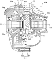
- 2 is a configuration diagram showing an outline of a configuration of a differential device 50.
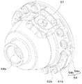
- FIG. FIG. 3 is an external view of a differential case 54 of FIG.
- FIG. 3 is an external view of the differential case 54 of FIG. 2 as viewed obliquely from the upper right. It is explanatory drawing which shows the inner periphery and outer periphery of the receiver 70, the outer periphery of the side gear washer 56, etc.
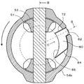
- FIG. It is a block diagram which shows the outline of a structure of the differential apparatus 50B of 2nd Embodiment.
- FIG. 7 is a simplified cross-sectional view showing the AA cross section of FIG.
- FIG. 6 is an explanatory diagram schematically showing a state in which lubricating oil is supplied from an oil hole 59 into the differential case 54B when the differential case 54B rotates.
- FIG. 1 is a schematic configuration diagram of a power transmission device 20 including a differential device 50 according to the first embodiment of the present disclosure.
- the power transmission device 20 of the first embodiment is connected to a crankshaft of an engine (not shown) mounted on a front wheel drive vehicle and can transmit power from the engine to left and right drive wheels (front wheels) DW.
- the power transmission device 20 includes a known fluid transmission device (torque converter) and an automatic transmission device 22 having an automatic transmission, a gear mechanism (gear train) 40, a differential device (differential mechanism) 50, and the like. Is provided.
- the gear mechanism 40 includes a counter drive gear 41 fixed to an output shaft (not shown) of the automatic transmission 22 and a counter driven gear 43 fixed to a counter shaft 42 extending in parallel with the output shaft and meshing with the counter drive gear 41. And a drive pinion gear (final drive gear) 44 formed (or fixed) on the counter shaft 42, and a differential ring gear (final driven gear) 45 that meshes with the drive pinion gear 44 and is connected to the differential device 50.
- FIG. 2 is a configuration diagram showing an outline of the configuration of the differential device 50.
- FIG. 3 is an external view of the differential case 54 shown in FIG. 2 as viewed from the upper left.
- FIG. 4 shows the upper case of the differential case 54 shown in the upper right. It is the external view seen from.
- the differential device 50 includes a pair (two) of pinion gears 51 and a pair (two) of side gears that are fixed to the drive shaft 28 and mesh with the pair of pinion gears 51 at right angles. 52, a pinion shaft 53 that supports the pair of pinion gears 51, and a differential case 54 that houses the pair of pinion gears 51 and the pair of side gears 52 and that is connected (fixed) to the above-described differential ring gear 45.
- each pinion gear 51 and each side gear 52 are configured as bevel gears.
- a pinion gear washer 55 is disposed between each of the pinion gears 51 and the differential case 54, and a side gear washer 56 is disposed between each of the side gears 52 and the differential case 54.
- the differential case 54 is rotatably supported coaxially with the drive shaft 28 via a bearing 26 by a transmission case 24 constituted by two case members 24a and 24b.
- the differential case 54 includes an annular case member 54a formed with a drive shaft hole 58a through which the left drive shaft 28 in FIG. 2 is inserted, a drive shaft hole 58b through which the right drive shaft 28 in FIG. And a bowl-shaped case member 54b formed with a pinion shaft hole 57 through which the middle upper pinion shaft 53 is inserted.
- Bolt holes 62a and 62b are formed in the flange portions 61a and 61b near the outer peripheral edges of the case members 54a and 54b, and the case members 54a and 54b are fastened together with the diff ring gear 45 by a plurality of bolts.
- the differential case 54 has two holes for supplying and discharging lubricating oil at the same diameter position from the rotation center of the rotation shaft of the drive shaft 28. Only the oil holes 59 are formed. Lubricating oil is supplied to the two oil holes 59 from an oil passage 30 formed in the transmission case 24.
- the differential case 54 (case member 54a) is provided with an annular receiver 70 having a substantially L-shaped cross section that functions as an oil outflow regulating member for regulating the outflow of lubricating oil in the differential case 54.
- the receiver 70 has an inner circumference smaller than the outer circumference of the side gear washer 56 with respect to the rotation center of the rotation shaft of the drive shaft 28, and the outer circumference is larger from the rotation center of the rotation shaft of the drive shaft 28 to the outermost edge of the oil hole 59. It is formed as follows.
- the outer peripheral portion of the receiver 70 is bent along the flange portion 61a of the case member 54a and extends to the left side in FIG. 2, and its end 72 is in contact with the race 27 of the bearing 26.
- the receiver 70 is prevented from coming off by the end portion 72 coming into contact with the race 27 of the bearing 26.
- the receiver 70 is formed so that the outer peripheral side is in contact with the case member 54a and the inner peripheral side is bent to the left side in FIG. 2 so as not to contact the case member 54a. For this reason, the lubricating oil is supplied to and discharged from the inner peripheral side that is not in contact with the case member 54a.
- FIG. 5 shows the inner periphery and outer periphery of the receiver 70 and the outer periphery of the side gear washer 56 when one of the oil holes 59 is located at the lowermost part.
- the level of the lubricating oil in the differential case 54 when the differential case 54 is not rotating depends on the positions of the two oil holes 59, but becomes the lowest when one of the oil holes 59 is located at the lowermost part.
- the liquid level of the lubricating oil is the lowermost part of the inner periphery of the receiver 70 (two-dot chain line A in FIGS. 2 and 5).
- the outer circumference side of the side gear washer 56 is immersed in the lubricating oil even when the liquid level of the lubricating oil is lowest. Except when one of the oil holes 59 is located at the lowermost part, the liquid level of the lubricating oil becomes higher, so that the outer peripheral side of the side gear washer 56 is naturally immersed in the lubricating oil. Therefore, when the differential case 54 is not rotating, the lubricating oil can always be supplied to the side gear washer 56 regardless of the rotational position of the oil hole 59.
- a receiver 70 formed in an annular shape so that the inner periphery is smaller than the outer periphery of the side gear washer 56 with respect to the rotation center of the shaft and the outer periphery is larger from the rotation center of the rotation shaft of the drive shaft 28 to the outermost edge of the oil hole 59.
- the differential case 54 is lubricated to a position having the same diameter from the rotation center of the rotation shaft of the drive shaft 28 as a hole in addition to the pinion shaft hole 57 and the pair of drive shaft holes 58a and 58b.
- Only the two oil holes 59 for supplying and discharging oil are formed.
- the number of oil holes is not limited to two, and the oil holes may be located at the same diameter from the rotation center of the rotation shaft of the drive shaft 28. There may be three or more, or one.
- the receiver 70 is formed such that the outer peripheral portion of the receiver 70 is bent along the flange portion 61a of the case member 54a, and the end portion 72 thereof is in contact with the race 27 of the bearing 26.
- the end portion 72 of the receiver 70 may not contact the race 28 of the bearing 26.
- a protrusion or the like for preventing the receiver 70 from coming off by contacting the end 72 of the receiver 70 may be formed on the case member 54a.
- the differential device 50B of the second embodiment is incorporated in a power transmission device connected to a crankshaft of an engine (not shown) mounted on a front wheel drive vehicle, similarly to the differential device 50 according to the first embodiment shown in FIG. Yes.
- the differential device 50B of the second embodiment is provided with a lubricating oil retaining member 80 instead of the receiver 70, and the differential case 54B has an oil hole 59B as a hole in addition to the nonion shaft hole 57 and the pair of drive shaft holes 58a and 58b.
- the same configuration as that of the differential device 50 according to the first embodiment described above is used except that only the first embodiment is formed.
- FIG. 6 is a block diagram showing an outline of the configuration of the differential device 50B
- FIG. 7 is a simplified cross-sectional view showing the AA cross section of FIG. 6 in a simplified manner.
- FIG. 6 shows a BB cross section of FIG.
- the arrow on the left side of FIG. 7 indicates the rotation direction of the differential case 54B when the vehicle moves forward.
- the differential case 54B in addition to the pinion shaft hole 57 and the pair of drive shaft holes 58a and 58b, only an oil hole 59B for supplying and discharging lubricating oil is formed. Lubricating oil is supplied from the supply hole 32 of the lubricating oil supply pipe 30 to the oil hole 59B.
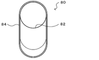
- FIG. 8 is a plan view of the lubricant holding member 80 as viewed from the arrow C in FIG. As shown in FIGS. 6 to 8, the lubricating oil holding member 80 is formed so as to stand inward of the differential case 54B so as to surround the entire circumference of the oil hole 59B and the cylindrical insertion portion 82 to be inserted into the oil hole 59B.
- the wall portion 84 is formed.
- the front side (upper side in FIG. 7, upper side in FIG.
- the wall portion 84 with respect to the rotation direction of the differential case 54 ⁇ / b> B when the vehicle moves forward is formed continuously from the insertion portion 82 over the entire circumference.
- the rear side (the lower side in FIG. 7 and the lower side in FIG. 8) of the differential case 54B when the vehicle advances 84 is formed so as to spread rearward and to be inclined rearward.
- the wall portion 84 is located on the inner peripheral side from the outer periphery of the side gear washer 56, and the top portion 86 is centered on the rotation center of the differential case 54B as indicated by the broken line in FIG.
- the circular arc shape is formed.
- FIG. 9 shows how the lubricating oil is supplied from the supply hole 32 of the lubricating oil supply pipe 30 into the differential case 54B through the oil hole 59B.
- 9A to 9C show the rotational position of the differential case 54B and the position of the oil droplet 90 over time, and the arrows on the left side of FIGS. 9A to 9C indicate the rotational direction of the differential case 54B.
- the downward arrows below the oil droplets 90 in (a) to (c) indicate the direction in which the oil droplet 90 falls.
- the oil droplet 90 ((a) in FIG. 9) located at the center of the fitting insertion portion 82 of the lubricating oil holding member 80 is a little time passes and the differential case 54B. Is rotated, the oil hole 59B in the region surrounded by the wall 84 of the lubricating oil holding member 80 is positioned rearward in the rotation direction ((b) in FIG. 9).
- the broken line arrow in FIG. 9C is the relative drop direction (supply direction) of the oil droplet 90 with respect to the rotation of the differential case 54B.
- the oil droplet 90 is supplied into the differential case 54 ⁇ / b> B without colliding with the wall portion 84 by forming the rear side of the wall portion 84 so as to spread rearward and inclined rearward.
- the case where the oil droplets 90 are supplied from the supply holes 32 of the lubricating oil supply pipe 30 to the oil holes 59B has been described. However, the description is continued from the supply holes 32 of the lubricating oil supply pipe 30. The same applies when the lubricating oil is supplied.
- the wall portion 84 of the lubricating oil holding member 80 is formed so as to be closer to the inner peripheral side than the outer periphery of the side gear washer 56 and the top portion 86 is formed in an arc shape even when the differential case 54B is stopped. Is to be supplied to the side gear washer 56.
- the level of the lubricating oil in the differential case 54B when the differential case 54B is not rotating is lowest when the oil hole 59B is positioned at the lowermost portion, although it depends on the position of the oil hole 59B. In this case, as shown in FIG. 6, the liquid level of the lubricating oil is the lowermost portion (two-dot chain line D in FIG. 6) at the top 86 of the wall 84 of the lubricating oil holding member 80.
- the lowermost portion of the top portion 86 of the wall portion 84 of the lubricating oil holding member 80 is located above the outer periphery of the side gear washer 56, so that even when the liquid level of the lubricating oil is lowest, The outer peripheral side of the side gear washer 56 is immersed in the lubricating oil. Except when the oil hole 59B is located at the lowermost part, the liquid level of the lubricating oil becomes higher, so that the outer peripheral side of the side gear washer 56 is naturally immersed in the lubricating oil. Therefore, when the differential case 54B is not rotating, the lubricating oil can always be supplied to the side gear washer 56 regardless of the rotational position of the oil hole 59B.
- the oil hole 59B is formed as a hole in the differential case 54B in addition to the pinion shaft hole 57 and the pair of drive shaft holes 58a and 58b, and the oil hole is formed inside the differential case 54B.
- Lubricating oil can be held in the differential case 54B by attaching the lubricating oil holding member 80 having the wall portion 84 standing so as to surround 59B to the oil hole 59B.
- the wall portion 84 of the lubricating oil retaining member 70 is formed such that the top portion 86 is located on the inner peripheral side from the outer periphery of the side gear washer 56, the differential case 54B is rotating or not rotating. Lubricating oil can be supplied to the side gear washer 56.
- the wall portion 84 of the lubricating oil holding member 80 so that the rear side spreads backward and inclines backward with respect to the rotation direction of the differential case 54B when the vehicle moves forward, the lubricating oil is removed from the oil hole 59B. Can be smoothly supplied to the inside of the differential case 54B.
- the differential case 54B is formed with only one oil hole 59B for supplying and discharging lubricating oil as a hole in addition to the pinion shaft hole 57 and the pair of drive shaft holes 58a and 58b.
- the number of oil holes is not limited to one and may be two or more.
- the lubricating oil holding member 80 may be attached to each oil hole.
- the wall portion 84 of the lubricating oil retaining member 70 is formed such that the top portion 86 is located on the inner peripheral side from the outer periphery of the side gear washer 56, but the top portion 86 is the side gear washer 56. It may be formed so as to be on the outer peripheral side of the outer periphery.
- the wall portion 84 of the lubricating oil retaining member 80 is formed so that the rear side spreads backward and inclines backward with respect to the rotational direction of the differential case 54B when the vehicle advances.
- the rear side of the wall portion 84 with respect to the rotation direction of the differential case 54B when the vehicle moves forward is formed so as to spread rearward, but may not be formed so as to be inclined rearward. It is good also as what is formed so that it may incline back, but is not formed so that it may spread back.
- the rear side of the wall portion 84 with respect to the rotation direction of the differential case 54B when the vehicle moves forward may be formed so as to be continuously cut off from the fitting insertion portion 82 in the same manner as the front side.
- the lubricating oil holding member 80 is configured by the fitting insertion portion 82 and the wall portion 84, but the lubricating oil holding member may be configured by only the wall portion. In this case, the lubricating oil holding member may be a separate member from the case member 54a of the differential case 54B, or the same member.
- the differential device (50) of the present disclosure includes: A pinion gear (51) supported by a pinion shaft (53), a pair of side gears (52) meshing with the pinion gear (51) and fixed to a pair of drive shafts (28), respectively, and the pinion shaft (53) Are formed, and a pair of drive shaft holes (58a, 58b) through which the pair of drive shafts (28) are inserted, and the pinion gear (51) and the pair of side gears ( 52) and a differential gear case (54, 54a, 54b) and a side gear washer (56) disposed between the pair of side gears (52) and the differential case (54, 54a, 54b).
- a device (50) comprising: In the differential case (54, 54a, 54b), in addition to the pinion shaft hole (57) and the pair of drive shaft holes (58a, 58b), lubrication provided on the outer diameter from the side gear washer (56). Only at least one oil hole (59) for oil supply and discharge is formed, An oil outflow restricting member (70) extending to an inner diameter smaller than the outer periphery of the side gear washer (56) and storing oil in the differential case (54, 54a, 54b) from the oil hole (59) to the inner diameter; Differential device.
- the differential case (54, 54a, 54b) accommodates a pinion gear (51) and a pair of side gears (52), and the side gear (51) and the differential case (54, 54a). , 54b) is provided with a side gear washer (56).
- the differential case (54, 54a, 54b) includes a pinion shaft hole (57) through which the pinion shaft (53) is inserted and a pair of drive shaft holes (58a, 58b) through which the pair of drive shafts (28) are inserted.
- An oil outflow restricting member (70) is provided which extends to an inner diameter smaller than the outer periphery of the side gear washer (56) and accumulates oil in the differential case (54, 54a, 54b) from the oil hole (59) to the inner diameter.
- the oil outflow restricting member (70) extends to an inner diameter smaller than the outer periphery of the side gear washer (56). Since oil is accumulated in the differential case (54, 54a, 54b) from the hole (59) to the inner diameter, lubricating oil can be supplied to the side gear washer (56).
- the lubricating oil in the differential case (54, 54a, 54b) is discharged from the oil hole (59) by centrifugal force, but the oil spill restricting member (70) Since the lubricating oil on the outer peripheral side from the inner peripheral is held in the differential case (54, 54a, 54b), the lubricating oil can be supplied to the side gear washer (56). As a result, the lubricating oil can be supplied to the side gear washer (56) regardless of the rotation of the differential case (54, 54a, 54b).
- the oil hole (59) extends from a rotation center of a rotation shaft of the drive shaft (28) on one side gear (52) side of the pair of side gears (52).
- One side gear washer (56) is formed on the outer peripheral side, and the oil outflow restricting member (70) has an inner circumference smaller than the outer circumference of the side gear washer (56) with respect to the rotation center of the rotating shaft.
- the outer periphery is a larger annular member from the rotation center to the outermost edge of the oil hole (59), and may be attached to the one side gear (52) side of the differential case (54, 54a, 54b). .
- the oil spill regulating member (70) has an outer peripheral side in contact with the differential case (54, 54a, 54b) and an inner peripheral side in non-contact with the differential case (54, 54a, 54b). It is good also as what is attached so that a part of said oil hole (59) may open.
- the oil spill restricting member (70) is prevented from coming off by a race (27) of a bearing (26) that rotatably supports the differential case (54, 54a, 54b). It is good as it is. In this way, there is no need to provide a member for preventing the oil spill restricting member (70) from coming off.
- the oil spill regulating member (70) has an end portion (72) extending along the rotation axis of the drive shaft (28) fixed to the one side gear (52) on the outer periphery, and the race (27 ) May be prevented from coming off.
- the oil hole (59B) is provided on the same circumference shifted in the circumferential direction from the pinion shaft (53), and the oil outflow regulating member (70) is provided in the differential case.
- (54B, 54a, 54b) is provided with a lubricating oil retaining member (80) that defines a wall portion that stands up toward the inside of the differential case (54B, 54a, 54b) around the entire circumference of the oil hole (59) inside (54B, 54a, 54b). It may be a thing.
- the wall portion (84) of the lubricating oil retaining member (80) regulates the discharge of the lubricating oil in the differential case (54B, 54a, 54b), so the lubricating oil is injected into the differential case (54B, 54a, 54b). Can be held.
- the lubricating oil holding member (80) has the differential case (54B, 54a, 54b) in the oil hole (59B) as a vehicle.
- the wall portion (84) on the rear side with respect to the rotation direction at the time of forward movement may be formed so as to be separated rearward from the oil hole (59B). In this way, when the lubricating oil is supplied to the oil hole (59B) when the vehicle moves forward, the lubricating oil can easily enter the interior without colliding with the wall portion (84).
- the lubricating oil holding member (80) includes the differential case (54B, 54a, 54b) of the oil hole (59B). It is good also as what is formed so that the wall part (84) of the back side may incline back with respect to the rotation direction at the time of vehicle advance. In this way, when the lubricating oil is supplied to the oil hole (59B) when the vehicle moves forward, the lubricating oil can easily enter the interior without colliding with the wall portion (84).
- the lubricating oil holding member (80) extends from the rotation shaft of the differential case (54B, 54a, 54b) to the wall portion (84).
- the wall portion (84) may be formed such that the length to the top portion (86) is closer to the inner peripheral side than the outer periphery of the side gear washer (56). In this way, the lubricating oil can be supplied to the side gear (52) and the side gear washer (56) when the vehicle moves forward.
- the top portion (86) of the wall portion (84) of the lubricant holding member (80) is the differential case (54B, 54a, It is good also as what is formed so that it may become circular arc centering on the rotating shaft of 54b). In this way, the lubricating oil can be stably held when the differential case (54B, 54a, 54b) rotates.
- this indication is not limited to such embodiment at all, and can be implemented with various forms within the range which does not deviate from the gist of this indication. Of course.
- This disclosure can be used in the differential device manufacturing industry and the like.
Landscapes
- Engineering & Computer Science (AREA)
- General Engineering & Computer Science (AREA)
- Mechanical Engineering (AREA)
- General Details Of Gearings (AREA)
- Retarders (AREA)
Abstract
Priority Applications (4)
| Application Number | Priority Date | Filing Date | Title |
|---|---|---|---|
| JP2017509366A JP6390786B2 (ja) | 2015-03-27 | 2016-02-18 | デファレンシャル装置 |
| US15/541,526 US10408336B2 (en) | 2015-03-27 | 2016-02-18 | Differential apparatus |
| CN201680017838.9A CN107429812A (zh) | 2015-03-27 | 2016-02-18 | 差速器装置 |
| DE112016000262.9T DE112016000262T5 (de) | 2015-03-27 | 2016-02-18 | Differenzialvorrichtung |
Applications Claiming Priority (4)
| Application Number | Priority Date | Filing Date | Title |
|---|---|---|---|
| JP2015-066883 | 2015-03-27 | ||
| JP2015066883 | 2015-03-27 | ||
| JP2015068183 | 2015-03-30 | ||
| JP2015-068183 | 2015-03-30 |
Publications (1)
| Publication Number | Publication Date |
|---|---|
| WO2016158059A1 true WO2016158059A1 (fr) | 2016-10-06 |
Family
ID=57006666
Family Applications (1)
| Application Number | Title | Priority Date | Filing Date |
|---|---|---|---|
| PCT/JP2016/054672 Ceased WO2016158059A1 (fr) | 2015-03-27 | 2016-02-18 | Appareil différentiel |
Country Status (5)
| Country | Link |
|---|---|
| US (1) | US10408336B2 (fr) |
| JP (1) | JP6390786B2 (fr) |
| CN (1) | CN107429812A (fr) |
| DE (1) | DE112016000262T5 (fr) |
| WO (1) | WO2016158059A1 (fr) |
Cited By (3)
| Publication number | Priority date | Publication date | Assignee | Title |
|---|---|---|---|---|
| WO2019177020A1 (fr) * | 2018-03-15 | 2019-09-19 | アイシン・エィ・ダブリュ株式会社 | Dispositif d'entraînement de véhicule |
| JP2019168005A (ja) * | 2018-03-22 | 2019-10-03 | 本田技研工業株式会社 | 差動装置 |
| JPWO2021137279A1 (fr) * | 2019-12-30 | 2021-07-08 |
Families Citing this family (10)
| Publication number | Priority date | Publication date | Assignee | Title |
|---|---|---|---|---|
| USD900874S1 (en) * | 2016-11-17 | 2020-11-03 | Eaton Intelligent Power Limited | Differential case |
| JP6562050B2 (ja) * | 2017-08-21 | 2019-08-21 | トヨタ自動車株式会社 | 車両用動力伝達装置 |
| USD941880S1 (en) * | 2018-01-19 | 2022-01-25 | Eaton Intelligent Power Limited | Differential case |
| DE102020128331A1 (de) * | 2020-10-28 | 2022-04-28 | Deere & Company | Differential mit Schmierstoffkanal |
| EP4246015B1 (fr) | 2020-11-12 | 2025-07-30 | Aisin Corporation | Engrenage différentiel |
| JP7760966B2 (ja) * | 2022-06-29 | 2025-10-28 | 株式会社アイシン | 差動ギヤ装置 |
| US12173786B1 (en) * | 2023-07-11 | 2024-12-24 | Schaeffler Technologies AG & Co. KG | Oil collector for mechanical limited slip differential |
| DE102023122165A1 (de) * | 2023-08-18 | 2025-02-20 | Bayerische Motoren Werke Aktiengesellschaft | Gehäuse für ein Getriebe, Getriebe für ein Kraftfahrzeug sowie Kraftfahrzeug |
| DE102024123598B4 (de) * | 2024-08-19 | 2026-02-26 | Schaeffler Technologies AG & Co. KG | Drehmomentkopplungsvorrichtung mit einem Fluidleitelement |
| DE102024126249B4 (de) * | 2024-09-12 | 2026-03-26 | Schaeffler Technologies AG & Co. KG | Drehmomentkopplungsvorrichtung mit einem Fluidleitelement |
Citations (3)
| Publication number | Priority date | Publication date | Assignee | Title |
|---|---|---|---|---|
| JPS502030U (fr) * | 1973-05-04 | 1975-01-10 | ||
| JPS57157U (fr) * | 1980-05-30 | 1982-01-05 | ||
| JP2008138780A (ja) * | 2006-12-01 | 2008-06-19 | Honda Motor Co Ltd | ディファレンシャル装置の潤滑構造 |
Family Cites Families (9)
| Publication number | Priority date | Publication date | Assignee | Title |
|---|---|---|---|---|
| JP2002174327A (ja) | 2000-12-08 | 2002-06-21 | Yanagawa Seiki Co Ltd | デファレンシャル |
| US7178426B2 (en) * | 2004-09-23 | 2007-02-20 | Dana Corporation | Enhanced lubrication system for drive axle assemblies |
| US8096913B2 (en) * | 2008-10-13 | 2012-01-17 | Traxxas Lp | Locking differential assembly for a model vehicle |
| US8409044B2 (en) * | 2008-10-23 | 2013-04-02 | American Axle & Manufacturing, Inc. | Differential lubrication feed system in a drive axle assembly |
| US8083628B2 (en) * | 2009-01-19 | 2011-12-27 | GM Global Technology Operations LLC | Differential carrier assembly for a vehicle |
| CN201496508U (zh) * | 2009-09-10 | 2010-06-02 | 东风汽车公司 | 轴间差速器支撑垫润滑结构 |
| JP5273411B2 (ja) * | 2011-06-29 | 2013-08-28 | トヨタ自動車株式会社 | ディファレンシャルギヤ装置の潤滑構造 |
| CN102312995B (zh) * | 2011-08-17 | 2012-12-05 | 湖南中联重科车桥有限公司 | 贯通式驱动桥的轴间差速器润滑结构和车辆 |
| US9797503B2 (en) * | 2015-05-12 | 2017-10-24 | Caterpillar Inc. | Direct torque path differential having spiderless pinions |
-
2016
- 2016-02-18 US US15/541,526 patent/US10408336B2/en not_active Expired - Fee Related
- 2016-02-18 WO PCT/JP2016/054672 patent/WO2016158059A1/fr not_active Ceased
- 2016-02-18 DE DE112016000262.9T patent/DE112016000262T5/de not_active Withdrawn
- 2016-02-18 CN CN201680017838.9A patent/CN107429812A/zh active Pending
- 2016-02-18 JP JP2017509366A patent/JP6390786B2/ja not_active Expired - Fee Related
Patent Citations (3)
| Publication number | Priority date | Publication date | Assignee | Title |
|---|---|---|---|---|
| JPS502030U (fr) * | 1973-05-04 | 1975-01-10 | ||
| JPS57157U (fr) * | 1980-05-30 | 1982-01-05 | ||
| JP2008138780A (ja) * | 2006-12-01 | 2008-06-19 | Honda Motor Co Ltd | ディファレンシャル装置の潤滑構造 |
Cited By (5)
| Publication number | Priority date | Publication date | Assignee | Title |
|---|---|---|---|---|
| WO2019177020A1 (fr) * | 2018-03-15 | 2019-09-19 | アイシン・エィ・ダブリュ株式会社 | Dispositif d'entraînement de véhicule |
| JP2019168005A (ja) * | 2018-03-22 | 2019-10-03 | 本田技研工業株式会社 | 差動装置 |
| JPWO2021137279A1 (fr) * | 2019-12-30 | 2021-07-08 | ||
| WO2021137279A1 (fr) * | 2019-12-30 | 2021-07-08 | ジヤトコ株式会社 | Dispositif de transmission de puissance |
| JP7392220B2 (ja) | 2019-12-30 | 2023-12-06 | ジヤトコ株式会社 | 動力伝達装置 |
Also Published As
| Publication number | Publication date |
|---|---|
| US10408336B2 (en) | 2019-09-10 |
| DE112016000262T5 (de) | 2017-09-28 |
| JPWO2016158059A1 (ja) | 2017-10-26 |
| JP6390786B2 (ja) | 2018-09-19 |
| CN107429812A (zh) | 2017-12-01 |
| US20180038475A1 (en) | 2018-02-08 |
Similar Documents
| Publication | Publication Date | Title |
|---|---|---|
| JP6390786B2 (ja) | デファレンシャル装置 | |
| US11149838B2 (en) | Lubricating device for components within casing structure of vehicular power transmitting system | |
| WO2012153589A1 (fr) | Dispositif d'entraînement destiné à un véhicule | |
| JP5920235B2 (ja) | 車両用駆動装置 | |
| CN106015534B (zh) | 差动装置 | |
| CN109563918B (zh) | 分动装置及动力传递装置 | |
| JP2016191418A (ja) | 差動装置 | |
| JP5462033B2 (ja) | 変速機のオイル供給装置 | |
| US20160290487A1 (en) | Vehicle differential device | |
| JP6384466B2 (ja) | 差動装置 | |
| JP2015048890A (ja) | 車両用差動歯車装置における潤滑構造 | |
| JP2014190374A (ja) | ディファレンシャル装置 | |
| JP2018025259A (ja) | 動力伝達装置 | |
| JP6636876B2 (ja) | トランスファー装置 | |
| JP2019035494A (ja) | 車両用動力伝達装置 | |
| US8152382B2 (en) | Output tube assembly for drive axle covers and method of use | |
| JP2013050147A (ja) | 自動車用変速機 | |
| JP6510382B2 (ja) | 動力伝達装置 | |
| JP2021162136A (ja) | 変速機の潤滑構造 | |
| KR101641000B1 (ko) | 변속기 유닛의 베어링 윤활 장치 | |
| JP2012202525A (ja) | デフケース | |
| JP2006144993A (ja) | リバースアイドラ軸の潤滑構造 | |
| JP2012237352A (ja) | 潤滑油供給装置 | |
| JP2011185402A (ja) | 車両用差動歯車装置 | |
| JP6636878B2 (ja) | 動力伝達装置 |
Legal Events
| Date | Code | Title | Description |
|---|---|---|---|
| 121 | Ep: the epo has been informed by wipo that ep was designated in this application |
Ref document number: 16771943 Country of ref document: EP Kind code of ref document: A1 |
|
| ENP | Entry into the national phase |
Ref document number: 2017509366 Country of ref document: JP Kind code of ref document: A |
|
| WWE | Wipo information: entry into national phase |
Ref document number: 15541526 Country of ref document: US |
|
| WWE | Wipo information: entry into national phase |
Ref document number: 112016000262 Country of ref document: DE |
|
| 122 | Ep: pct application non-entry in european phase |
Ref document number: 16771943 Country of ref document: EP Kind code of ref document: A1 |