WO2016158106A1 - 摩擦ローラ式減速機 - Google Patents
摩擦ローラ式減速機 Download PDFInfo
- Publication number
- WO2016158106A1 WO2016158106A1 PCT/JP2016/055533 JP2016055533W WO2016158106A1 WO 2016158106 A1 WO2016158106 A1 WO 2016158106A1 JP 2016055533 W JP2016055533 W JP 2016055533W WO 2016158106 A1 WO2016158106 A1 WO 2016158106A1
- Authority
- WO
- WIPO (PCT)
- Prior art keywords
- roller
- ring
- peripheral surface
- sun
- outer peripheral
- Prior art date
- Legal status (The legal status is an assumption and is not a legal conclusion. Google has not performed a legal analysis and makes no representation as to the accuracy of the status listed.)
- Ceased
Links
Images


Classifications
-
- F—MECHANICAL ENGINEERING; LIGHTING; HEATING; WEAPONS; BLASTING
- F16—ENGINEERING ELEMENTS AND UNITS; GENERAL MEASURES FOR PRODUCING AND MAINTAINING EFFECTIVE FUNCTIONING OF MACHINES OR INSTALLATIONS; THERMAL INSULATION IN GENERAL
- F16H—GEARING
- F16H13/00—Gearing for conveying rotary motion with constant gear ratio by friction between rotary members
- F16H13/06—Gearing for conveying rotary motion with constant gear ratio by friction between rotary members with members having orbital motion
- F16H13/08—Gearing for conveying rotary motion with constant gear ratio by friction between rotary members with members having orbital motion with balls or with rollers acting in a similar manner
-
- F—MECHANICAL ENGINEERING; LIGHTING; HEATING; WEAPONS; BLASTING
- F16—ENGINEERING ELEMENTS AND UNITS; GENERAL MEASURES FOR PRODUCING AND MAINTAINING EFFECTIVE FUNCTIONING OF MACHINES OR INSTALLATIONS; THERMAL INSULATION IN GENERAL
- F16H—GEARING
- F16H13/00—Gearing for conveying rotary motion with constant gear ratio by friction between rotary members
- F16H13/02—Gearing for conveying rotary motion with constant gear ratio by friction between rotary members without members having orbital motion
- F16H13/04—Gearing for conveying rotary motion with constant gear ratio by friction between rotary members without members having orbital motion with balls or with rollers acting in a similar manner
-
- F—MECHANICAL ENGINEERING; LIGHTING; HEATING; WEAPONS; BLASTING
- F16—ENGINEERING ELEMENTS AND UNITS; GENERAL MEASURES FOR PRODUCING AND MAINTAINING EFFECTIVE FUNCTIONING OF MACHINES OR INSTALLATIONS; THERMAL INSULATION IN GENERAL
- F16H—GEARING
- F16H13/00—Gearing for conveying rotary motion with constant gear ratio by friction between rotary members
- F16H13/10—Means for influencing the pressure between the members
- F16H13/14—Means for influencing the pressure between the members for automatically varying the pressure mechanically
Definitions
- the present invention relates to a friction roller type speed reducer.
- a friction roller type speed reducer 500 described in Patent Document 1 includes a sun roller 511 connected to an input shaft, an output shaft 512 having a holding cylinder 513 at one end, and a pair of ring roller elements.
- a ring roller 515 comprising 514A and 514B, a plurality of intermediate rollers 516 arranged in an annular space between the inner peripheral surface of the ring roller 515 and the outer peripheral surface of the sun roller 511, and a side surface of the ring roller element 514A
- the surface pressure applying device 517 is provided.
- the outer peripheral surface of the sun roller 511 is a cylindrical surface whose outer diameter does not change in the axial direction.
- the inner peripheral surfaces of the ring roller elements 514A and 514B are partial conical surfaces that are inclined in a direction in which the inner diameter becomes larger toward the front end surfaces that are the mutually opposing surfaces of the ring roller elements 514A and 514B.
- the outer peripheral surface of the intermediate roller 516 is a cylindrical surface whose outer diameter does not change in the axial direction with respect to the axial direction, and the outer diameter decreases as both axial ends move toward the both axial ends of the intermediate roller 516. It is a partial conical surface inclined in the direction.
- the surface pressure applying device 517 is provided on the ring roller 515 side.
- the radius of rotation from the rotation center of the input shaft to the rolling contact portions of the inner peripheral surface of the ring roller 515 and the outer peripheral surface of each intermediate roller 516 is increased. ing. Therefore, the radial distance difference between the axial ends of the contact area (contact ellipse) in the rolling contact portion can be reduced with respect to the radial distance, and the peripheral speed difference generated in the contact ellipse can be suppressed small.
- the friction roller type speed reducer described in Patent Document 2 is rotatably supported between a sun roller, a ring roller disposed concentrically with the sun roller, and an outer peripheral surface of the sun roller and an inner peripheral surface of the ring roller.
- the sun roller is composed of a pair of sun roller elements, and by means of a loading cam mechanism, one sun roller element approaches or separates from the other sun roller element in the axial direction according to the transmission torque, and each of the sun roller element, the intermediate roller, and the ring roller The surface pressure is changed.
- the outer peripheral surface of the intermediate roller 516 has an arc shape.
- the rolling contact portion between the intermediate roller 116 and the ring roller elements 514A and 514B can be in a point contact state with a small contact area.
- the contact portion with the outer peripheral surface of the sun roller 511 which is a cylindrical surface becomes point contact, and the contact surface pressure increases.
- the intermediate roller 516 contacts the ring roller 515 at two locations, whereas the intermediate roller 516 contacts the sun roller 511 at one location, so that the contact surface pressure tends to increase. Therefore, an increase in contact surface pressure between the sun roller 511 and the intermediate roller 516 may affect the durability life of the sun roller 511 that rotates at a high speed.
- a needle bearing is generally arranged on the inner diameter side of a gear (roller) and supported so as to be rotatable and movable in the axial direction.
- the friction roller type has a particular problem that the roller is elastically deformed in the radial direction by a normal force applied to the roller. That is, in the case of the above configuration, the internal clearance of the needle bearing is reduced when the normal force applied to the intermediate roller is increased as the transmission torque is increased. Then, depending on the initial clearance setting of the needle bearing, the internal clearance may become negative. When the needle bearing has a negative clearance, the contact surface pressure of the traction surface becomes larger than the design value, and the durable life of the bearing is shortened. Further, in the needle bearing, a relative inclination (skew) is generated between the rotating shaft and the raceway surface of the inner and outer rings. This skew causes an axial load due to slip in the bearing.
- skew relative inclination
- the axial load caused by skew has a correlation with the total rolling element load. That is, in the configuration in which the needle bearing is disposed on the inner diameter portion of the intermediate roller, the bearing internal clearance tends to be negative, and the axial load due to skew increases. When axial force due to skew is generated in the roller, the surface pressure of the traction surface increases, which affects the life of the reduction gear.
- the present invention has been made in view of the above-mentioned problems.
- the first object of the present invention is to reduce slip loss between the intermediate roller and the ring roller without increasing the processing cost and reducing the durability of the sun roller.
- An object of the present invention is to provide a friction roller type speed reducer with reduced torque transmission efficiency.
- the second object is a friction roller type speed reducer that can smooth the displacement of the roller by loading and suppress the occurrence of friction and wear without being affected by the elastic deformation of the intermediate roller even when the transmission torque increases. Is to provide.
- the present invention has the following configuration. (1) A sun roller disposed concentrically with the input shaft, a ring roller disposed concentrically with the sun roller on an outer peripheral side of the sun roller, and an outer peripheral surface of the sun roller and an inner peripheral surface of the ring roller, A plurality of intermediate rollers that are rotatably supported around a rotation axis parallel to the input shaft and are in rolling contact with the outer peripheral surface of the sun roller and the inner peripheral surface of the ring roller, and the ring roller and the output shaft are connected.
- a friction roller type speed reducer comprising: a connecting portion; and a loading cam mechanism for changing a contact surface pressure of a rolling contact surface of each roller,
- the ring roller is composed of a pair of roller elements arranged in parallel in the axial direction of the input shaft, At least one of the pair of roller elements is a movable roller element movable in the axial direction,
- the loading cam mechanism is disposed only on the outer end surface side of the movable roller element in the axial direction, and displaces the movable roller element toward the other roller element according to the rotational torque of the input shaft.
- the outer peripheral surface of the sun roller is a concave curved surface in which the outer edge shape of the axial section is a single arc-shaped concave curve
- the outer peripheral surface of the intermediate roller is a friction roller type speed reducer in which the outer peripheral shape of the shaft section is a convex curved surface having a single arc-shaped convex curve.
- the loading cam mechanism is arranged to face the first cam groove provided at a plurality of locations along the circumferential direction of the outer end surface of the movable roller element, and to the outer end surface of the movable roller element.
- a cam ring provided with a second cam groove at a plurality of locations corresponding to the groove, and a plurality of rolling elements sandwiched between the first cam groove and the second cam groove, respectively.
- the cam groove and the second cam groove each have a shape in which the axial depth gradually changes along the circumferential direction and becomes shallower toward the circumferential end of the cam groove (1).
- the intermediate roller has the rotation shaft extending at both ends of a roller body having a traction surface on the outer peripheral surface that is in rolling contact with the outer peripheral surface of the sun roller and the inner peripheral surface of the ring roller,
- the holder has a gap between the inner surface of the holder and the end surface of the roller body so that the intermediate roller can move in the axial direction, and the rotation shaft is rotatable through a needle bearing and in the axial direction.
- Friction roller type speed reducer that is movably supported.
- the loading roller mechanism disposed on the ring roller side is provided, and the outer peripheral surface of the sun roller is a concave curved surface in which the outer edge shape of the shaft section is a single circular arc-shaped concave curve.
- the outer peripheral surface of the intermediate roller is a convex curved surface whose outer edge shape of the shaft section is a single circular arc-shaped convex curve, so that the contact area in the rolling contact portion between the intermediate roller and the ring roller without increasing the processing cost
- the difference in peripheral speed between the axial ends and the central portion can be reduced. Thereby, friction loss can be reduced and torque transmission efficiency can be improved.
- the durability of the sun roller can be improved by reducing the contact surface pressure at the rolling contact portion between the outer peripheral surface of the intermediate roller and the outer peripheral surface of the sun roller.
- the intermediate roller since the rotation shafts extended at both ends of the intermediate roller are supported by the holder via the needle bearing, the intermediate roller can be supported rotatably and movable in the axial direction. With this configuration, even if a normal force is applied to the intermediate roller according to the transmission torque, the internal clearance of the needle bearing does not change, so the durability life of the bearing can be improved. Further, the support span of the intermediate roller is widened, and skew is less likely to occur.
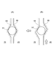
- FIG. 4 is a cross-sectional view taken along the line IV-IV in FIG. 3, showing a state where the loading cam mechanism does not generate thrust (A) and a state where thrust is generated (B).
- FIG. 25 is a cross-sectional perspective view taken along line IIXV-IIXV shown in FIG. 24. It is principal part sectional drawing of the conventional friction roller type reduction gear.
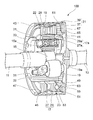
- FIG. 1 is a partial cross-sectional perspective view of the friction roller type speed reducer of the first configuration example, and FIG.
- the friction roller type speed reducer 100 includes a sun roller 15, a ring roller 17, a plurality of intermediate rollers 19, a ring roller 17, and an output shaft 13 that are arranged concentrically with the input shaft 11. And a loading cam mechanism 23.
- the sun roller 15 is a solid structure roller that is integrally formed at one end of the input shaft 11 concentrically with the input shaft 11.
- the outer peripheral surface 15a of the sun roller 15 is formed in a concave curved surface in which the outer edge shape of the axial section is a single circular arc-shaped concave curve.
- the ring roller 17 is a pair of ring roller elements arranged in parallel in the axial direction, and includes a fixed ring roller element 27 and a movable ring roller element 29 movable in the axial direction. These ring roller elements 27 and 29 are arranged concentrically with the sun roller 15 on the outer peripheral side of the sun roller 15 in a state of being accommodated inside the cup-shaped connecting portion 21.
- the inner peripheral surfaces 27a and 29a are annular inclined surfaces. These inclined surfaces have shorter distances from the opposite end surfaces 33 and 35 of the ring roller elements 27 and 29 toward the outer end surfaces 137 and 139 on the opposite side in the axial direction to the center of rotation of the intermediate roller 19. It is an inclined surface. That is, it is an inclined surface whose inner diameter becomes smaller toward the outer end surfaces 137 and 139. These inclined surfaces become rolling contact surfaces on which the intermediate roller 19 rolls.
- the inner peripheral surfaces 27a and 29a are not limited to the inclined surfaces, but may be concave curved surfaces in which the outer edge shape of the axial section is a single circular arc-shaped concave curve.
- the plurality of intermediate rollers 19 are supported by a support shaft (spinning shaft) 31 via a needle bearing 22 so as to be rotatable and displaceable in the axial direction, and the outer peripheral surface 15 a of the sun roller 15 and the inner peripheral surface of the ring roller 17. 17a. Both ends of the support shaft 31 are supported by the swing holder 32.
- the swing holder 32 is supported by the carrier 33 so that the intermediate roller 19 can move (swing) in the radial direction of the input shaft 11.
- the carrier 33 is fixed to a motor body (not shown) by a fastening member.
- each intermediate roller 19 is a convex curved surface whose outer edge shape in the axial section is a single arc-shaped convex curve, and is in rolling contact with the outer peripheral surface 15a of the sun roller 15 and the inner peripheral surface 17a of the ring roller 17, respectively.
- the connecting portion 21 is formed in a substantially disc shape and has a base end portion 37 whose central portion is connected to the output shaft 13 and an axially extending from the outer peripheral edge of the base end portion 37, and the ring roller 17 on the inner diameter side. And a cylindrical roller holding portion 39 to be held.
- a corrugated preload spring 67 Inside the roller holding portion 39, a corrugated preload spring 67, a cam ring 49, a ball 51 as a rolling element, a movable ring roller element 29, a fixed ring roller element 27, and a retaining ring 47 are provided from the base end portion 37 side. These members are inserted in this order, and each member is assembled to the roller holding portion 39.
- a plurality of concave grooves 43 are formed in the inner peripheral portion of the roller holding portion 39 along the axial direction. Further, a ring groove 45 (see FIG. 1) is formed in the circumferential direction on the inner peripheral portion of the end portion of the roller holding portion 39 opposite to the base end portion 37.
- the concave groove 43 accommodates a plurality of protrusions 28 formed at a plurality of locations on the outer peripheral portion of the fixed ring roller element 27 and projecting radially outward.
- the protrusion 28 of the fixed ring roller element 27 is engaged with the concave groove 43 of the roller holding portion 39 in a state where there is no rattling in the rotation direction, and the rotational torque between the roller holding portion 39 and the ring roller 17 can be transmitted. To do.
- the retaining groove 47 is inserted into the ring groove 45.
- the retaining ring 47 restricts the axial position of the fixed ring roller element 27 and fixes the fixed ring roller element 27 to the roller holding portion 39.
- the base end portion 37 of the connecting portion 21 is formed by cutting such as lathe processing, and the roller holding portion 39 is formed by plastic processing such as press molding. After the base end portion 37 and the roller holding portion 39 are formed as a single unit, the shaft cores can be made to coincide with each other at low cost with high accuracy by joining them together. Further, the base end portion 37 and the roller holding portion 39 are joined by beam welding. As a result, it is possible to perform heat bonding with a narrow bead and in a short time, and it is possible to suppress the occurrence of misalignment by minimizing thermal distortion.
- the cam ring 49 has a plurality of protrusions 61 that protrude radially outward from the outer periphery thereof.
- the protrusions 61 of the cam ring 49 engage with the concave grooves 43 of the roller holding portion 39, respectively, similarly to the protrusions 28 of the fixed ring roller element 27.
- the cam ring 49 has a notch 63 formed on the outer end surface on the output shaft side, in which a part on the outer diameter side is annularly cut, and a preload spring 67 is attached to the notch 63.
- the sun roller 15 rotates at a high speed, if there is a slight deviation of the center of gravity, there is a possibility that it becomes a vibration source of abnormal vibration.
- the sun roller 15 of this configuration is integrally formed with the input shaft 11, the balance can be easily corrected and the occurrence of vibration can be reduced.
- the sun roller 15 has high rigidity and a high resonance frequency, occurrence of abnormal vibration due to resonance is reduced.
- the sun roller 15 having a solid structure reduces the amount of elastic deformation of the sun roller 15 when a load described later is applied. Thereby, the axial displacement amount of the intermediate roller 19 and the ring roller 17 becomes small, and the contact state of the rolling contact surface can be maintained in a good state as designed.
- the loading cam mechanism 23 changes the contact surface pressure of each rolling contact surface of the sun roller 15, the ring roller 17, and the intermediate roller 19.
- first cam grooves 53 are formed on the outer end surface of the movable ring roller element 29 along the circumferential direction.
- the cam ring 49 is disposed so as to face the first cam groove 53, and a plurality of (three in the illustrated example) second cam grooves 55 are formed at circumferential positions corresponding to the first cam grooves 53.
- the balls 51 are sandwiched between the first cam groove 53 and the second cam groove 55, respectively.
- the axial groove depth is deepest at the center in the circumferential direction, and gradually changes along the circumferential direction. The shape becomes shallower toward the direction end.
- each ball 51 is located at the deepest part of each cam groove as shown in FIG. In this state, the cam ring 49 is pressed toward the movable ring roller element 29 by the elastic force of the preload spring 67.
- each ball 51 moves to a shallow portion of each cam groove 53, 55 as shown in FIG. This generates an axial thrust that presses the movable ring roller element 29 toward the fixed ring roller element 27.
- the axial thrust generated by the loading cam mechanism 23 reduces the distance between the fixed ring roller element 27 and the movable ring roller element 29.
- the contact surface pressure at the rolling contact portion between the inner peripheral surface 17a of the ring roller 17 and the outer peripheral surface 19a of each intermediate roller 19 increases.
- the contact surface pressure of the rolling contact portion between the outer peripheral surface 19a of each intermediate roller 19 and the outer peripheral surface 15a of the sun roller 15 also increases.
- the contact surface pressure of the plurality of rolling contact portions existing between the input shaft 11 and the output shaft 13 increases. This contact surface pressure increases as the torque transmitted between the input shaft 11 and the output shaft 13 increases.
- the axial thrust generated by the loading cam mechanism 23 causes elastic deformation of the traction parts such as the ring roller 17 and elastic deformation of each contact point.
- the intermediate roller 19 is axially displaced toward the fixed ring roller element 27 as the movable ring roller element 29 is displaced in the axial direction.
- an annular first stepped portion 41 having an inner peripheral surface parallel to the output shaft 13 is formed on the inner surface of the base end portion 37 of the connecting portion 21 on the input shaft 11 side.
- the outer end surface of the cam ring 49 is concentric with the center of the ring, and has a second stepped surface having an outer peripheral surface that engages with the first stepped portion 41 of the base end portion 37 of the connecting portion 21 along the axial direction.
- the portion 65 is formed to protrude in the axial direction.
- the shaft center of the cam ring 49 and the connecting portion 21 coincide with each other with high accuracy when the first stepped portion 41 and the second stepped portion 65 are fitted.
- the movable ring roller element 29 is also accurately positioned in the axial center position via the cam ring 49.
- the fixed ring roller element 27 is positioned in the radial direction by the intermediate roller 19.
- the intermediate roller 19 is positioned in the radial direction by a sun roller 15 concentric with the input shaft 11, and the input shaft 11 and the output shaft 13 are disposed concentrically.
- the sun roller 15, the intermediate roller 19, the ring roller 17, and the cam ring 49 are in a state in which the respective axes are accurately aligned.
- a preload spring 67 is disposed in the annular space 71 formed between the inner surface 69 of the base end portion 37 of the connecting portion 21 by the notch portion 63.
- the second stepped portion 65 is fitted to the first stepped portion 41 of the base end portion 37 in a state where the cam ring 49 is biased to the axially opposite side from the base end portion 37 by the preload spring 67. .
- This fitting length is longer than the elastic deformation allowance of the preload spring 67.
- FIG. 5 shows a state in which the intermediate roller 19 is offset in a no-load state.
- the center of the arc-shaped convex curved surface of the outer peripheral surface of the intermediate roller 19 is offset by a predetermined amount in the axial direction with respect to the center of the arc-shaped concave curved surface of the outer peripheral surface of the sun roller 15.
- an arcuate convex curved surface that is the outer peripheral surface 19a of the intermediate roller 19 The center C ⁇ b> 2 is offset from the center C ⁇ b> 1 of the arcuate concave curved surface that is the outer peripheral surface 15 a of the sun roller 15 by a predetermined amount L along the axial direction toward the cam ring 49.
- the center of the ring roller 17 that is in rolling contact with the intermediate roller 19 is also offset by a predetermined amount L. Details of the offset amount L will be described later.
- the intermediate roller 19 is also moved by the movable ring roller element 29 due to elastic deformation of the traction components such as the ring roller 17 and elastic deformation of each contact point. Is displaced in the axial direction toward the fixed ring roller element 27 side.
- the center C2 of the outer peripheral surface 19a of the intermediate roller 19 approaches the center C1 of the outer peripheral surface 15a of the sun roller 15.
- the offset amount L is reduced and the arcuate convex curved surface of the intermediate roller 19 and the arcuate concave curved surface of the sun roller 15 are displaced in a matching direction.
- the axial displacement amount of the intermediate roller 19 is approximately 1 ⁇ 2 of the axial displacement amount of the movable ring roller element 29.
- the cam ring 49 moves in the direction opposite to the pressing direction while crushing the preload spring 67, and the outer surface 73 of the second stepped portion 65 is The position of the cam ring 49 in the axial direction is restricted by contacting the inner surface 69 of the end portion 37.
- the interval between the fixed ring roller element 27 and the movable ring roller element 29 is reduced. Then, the contact surface pressure at the rolling contact portion between the inner peripheral surface 17a of the ring roller 17 constituted by the fixed ring roller element 27 and the movable ring roller element 29 and the outer peripheral surface 19a of each intermediate roller 19 increases. As the contact surface pressure increases, the contact surface pressure of the rolling contact portion between the outer peripheral surface 19a of each intermediate roller 19 and the outer peripheral surface 15a of the sun roller 15 also increases. As a result, the contact surface pressure of the plurality of rolling contact portions existing between the input shaft 11 and the output shaft 13 increases as the torque transmitted between the input shaft 11 and the output shaft 13 increases.
- each intermediate roller 19 rotates around the support shaft 31.
- the ring roller 17 is rotated by the rotation of each intermediate roller 19, and the projection 28 of the fixed ring roller element 27 is engaged with the concave groove 43 of the roller holding portion 39, so that the output shaft 13 connected to the roller holding portion 39 is Rotate.
- the contact surface pressure of each rolling contact portion is an appropriate surface pressure corresponding to the magnitude of torque transmitted between the input shaft 11 and the output shaft 13. Therefore, the occurrence of excessive slippage at each rolling contact portion and the increase in rolling resistance due to excessive contact surface pressure at each rolling contact portion are prevented.
- the fixed ring roller element 27 abuts against the retaining ring 47 and the axial position is restricted.
- the cam ring 49 is regulated in its axial position by the outer surface 73 of the second stepped portion 65 and the inner surface 69 of the base end portion 37 contacting each other. That is, the fixed ring roller element 27 having the protrusions 28 and the cam ring 49 having the protrusions 61 are engaged with the concave grooves 43 to transmit rotational power and are not substantially displaced in the axial direction. Therefore, it is possible to prevent wear at the engaging portion.
- FIG. 7 (A) and 7 (B) are explanatory views showing the effect of incorporating a friction roller type speed reducer in the electric vehicle drive device, and FIG. 8 shows the relationship between the axial movement amount of the intermediate roller and the transmission torque. It is a graph to show.
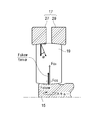
- the drive torque T of the electric vehicle is a characteristic in which the left half portion of the solid line Pa in FIG. That is, the acceleration performance at low speed is excellent, but it is not suitable for high-speed running.
- the relationship between the drive torque T and the traveling speed V is such that the two-dot chain line Pc in FIG. It becomes a characteristic. That is, high-speed travel is possible, but acceleration performance at low speed is impaired. Further, if a transmission is provided between the output shaft and the input unit and the reduction ratio of the transmission is changed according to the vehicle speed, a characteristic in which the left half and the right half of the solid line Pa are continuous can be obtained. This characteristic is substantially the same as that of a gasoline engine vehicle having the same level of output as indicated by the broken line Pd in FIG.
- the normal traveling state which is generally used frequently, is the medium to high speed shown by the region W in FIG.
- the low torque region is frequently used.
- Ta be the average driving torque in this high-use region.
- the drive torque T output to the output shaft 13 of the friction roller type speed reducer 100 of the present invention and the axial movement amount S of the intermediate roller 19 are approximately proportional as shown schematically in FIG. It is known that there is.
- the axial movement amount S of the intermediate roller 19 that outputs the average torque Ta in the region where the use frequency is high in normal traveling is set to the center C2 of the outer peripheral surface 19a of the intermediate roller 19 and the outer peripheral surface 15a of the sun roller 15. If the offset amount L with respect to the center C1 is set, most of the operating time of the friction roller type reduction gear 100 is in a state where the offset amount is zero, in other words, as shown in FIG.
- the center C1 of the arcuate concave curved surface and the center C2 of the arcuate convex curved surface of the intermediate roller 19 coincide with each other.
- Ta represents an average driving torque in the region W where the usage frequency is high.
- the axial movement amount S of the intermediate roller 19 that outputs this torque Ta is set to an offset amount L between the center C2 of the outer peripheral surface 19a of the intermediate roller 19 and the center C1 of the outer peripheral surface 15a of the sun roller 15.
- the outer peripheral surface 19a of the intermediate roller 19 is an arcuate convex curved surface. Therefore, the contact state between the ring roller 17 and the intermediate roller 19 becomes point contact, and slip loss at the rolling contact portion can be reduced. Further, since the crowning radius of the arc-shaped convex curved surface of the intermediate roller 19 can be reduced, the slip surface loss can be reduced by reducing the contact surface equivalent radius of the intermediate roller 19 and the ring roller 17.
- the outer peripheral surface 15a of the sun roller 15 is an arcuate concave curved surface. Therefore, the contact between the sun roller 15 and the intermediate roller 19 is a combination of an arcuate concave curved surface and an arcuate convex curved surface, and the area of the rolling contact area with the outer peripheral surface 19a of the intermediate roller 19 is increased. As a result, the contact surface pressure in the rolling contact area is reduced, the wear of the sun roller 15 is suppressed, and the durability of the reduction gear is improved.
- the loading cam mechanism 23 is provided on the ring roller 17 side. Therefore, compared to the configuration provided on the sun roller 15 side, the radial distance from the rotation center of the ring roller 17 to the rolling contact portion between each inner peripheral surface 17a of the ring roller 17 and the outer peripheral surface 19a of each intermediate roller 19 becomes longer. As a result, the peripheral speed difference at both ends of the rolling contact area (contact ellipse) can be kept small, the friction loss at the rolling contact portion on the ring roller 17 side is reduced, and torque can be transmitted with high efficiency.
- the outer peripheral surface 15a of the sun roller 15 is an arcuate concave curved surface whose outer edge shape in the axial section is a single arcuate concave curve, and its diameter is 30 mm. Further, the reverse crowning radius of the arc-shaped concave curved surface is 19 mm or more, which is 1.08 times or more the crowning radius of the intermediate roller 19.
- the outer peripheral surface 19a of the intermediate roller 19 is an arc-shaped convex curved surface in which the outer edge shape of the axial cross section is a single arc-shaped convex curve, and the diameter thereof is 50 mm.
- the diameter of the sun roller 15 is 30 mm
- the diameter of the intermediate roller 19 is 50 mm
- the transmission tangential force is 1000 N
- the decrease in torque transmission efficiency when the inclination angle ⁇ is 3 ° is 5%.
- the reverse crowning radius of the sun roller 15 is set to 19 mm or less, the torque transmission efficiency of the friction roller type reduction gear 100 is significantly reduced.
- the reverse crowning radius of the sun roller 15 and the crowning radius of the intermediate roller 19 are closer, the contact ellipse in the rolling contact area becomes larger, which is advantageous in improving durability.
- contact at unintended sites may occur due to variations in the crowning radii. Therefore, it is preferable that the reverse crowning radius of the sun roller 15 is 1.08 times or more the crowning radius of the intermediate roller, rather than making the reverse crowning radius of the sun roller 15 equal to the crowning radius of the intermediate roller 19.
- the axial displacement amount of the ring roller 17 is approximately twice the axial displacement amount of the intermediate roller 19, and when the axial displacement amount of the ring roller 17 becomes extremely large, the balls 51 fall off from the loading cam mechanism 23.
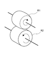
- FIG. 10 is an explanatory view schematically showing a pair of rollers
- FIG. 11A is a plan view seen from above FIG. 10A
- FIG. 10B is a schematic development of the rolling surface of the roller R2. It is explanatory drawing shown.
- a skew (angle ⁇ ) may occur in the roller R1 with respect to the roller R2.
- the roller R1 is in the direction along the track L OB (ideal rolling surface) indicated by the broken line in the drawing, that is, the circumferential direction of the roller R2, with respect to the roller R2. Rolling in a direction inclined by an angle ⁇ .
- the skew force F skew at this time can be expressed by the equation (1) by the traction coefficient ⁇ and the normal force F c .
- the traction coefficient ⁇ has a correlation with the slip ratio of the traction surface, and is generally known as a characteristic as shown in FIG.
- the horizontal axis of FIG. 12 corresponds to the above-described slip ratio (: tan ⁇ ). From this, it can be understood that as the skew angle ⁇ of the roller increases, the traction coefficient ⁇ increases and the skew force F skew increases.
- FIG. 13 is an explanatory diagram showing a state in which the intermediate roller 19 and the sun roller 15 are skewed when the ring roller 17 side is a tapered surface and the sun roller 15 side is a traction surface having no contact angle.
- the normal force F CS can be expressed by the equation (3) from the equation (2).
- FIG. 14 is an explanatory diagram showing a state in which the intermediate roller 19 and the ring roller 17 are skewed when the ring roller 17 side is a tapered surface and the sun roller 15 side is a traction surface having no contact angle.
- the normal force FCR2 can be expressed by the following equation (7) from the equation (6).
- the ring roller 17 side has been described as a tapered surface and the sun roller 15 side as a traction surface having no contact angle.
- the sun roller 15 side has a tapered surface and the ring roller 17 side has a contact angle.
- the above-mentioned conditions are the same for the traction surface not to be used.
- a roller having a loading cam mechanism (ring roller 17 in FIG. 1) is provided with a taper for converting an axial load into a normal force, and an inclination angle of the taper is ⁇ .
- tan ⁇ > 0.3 is obtained from n ⁇ ⁇ / tan ⁇ ⁇ 1, which is the above-mentioned convergence condition formula, and it is understood that the inclination angle ⁇ should be designed to be larger than 16.7 °.
- the maximum traction coefficient ⁇ max is a maximum value in a combination of these conditions.
- FIG. 15 is an explanatory diagram showing a situation in which skew occurs in the intermediate roller 19 and the sun roller 15 when the traction surfaces of both the sun roller 15 and the ring roller 17 are tapered surfaces.
- the initial normal force between the ring roller 17 and the intermediate roller 19 is F CS0
- the skew forces between the pair of ring roller elements 27 and 29 and the intermediate roller 19 are F skew1 and F skew2
- the inclination angle of the traction surface If ⁇ is ⁇ , the normal forces F CS1 and F CS2 between the pair of ring roller elements 27 and 29 and the intermediate roller 19 can be expressed by equations (9) and (10).
- the normal force F CS2 can be expressed by the equation (11) from the equation (10).
- each roller ⁇ Supporting form of each roller>
- the axial positions of the sun roller and the intermediate roller may be shifted due to the operation of the loading cam mechanism, misalignment of each roller, or skew.
- the arc center of the concave traction surface of the sun roller does not coincide with the arc center of the convex traction surface of the intermediate roller, and a contact angle is generated on the contact surface between the sun roller and the intermediate roller.
- any one of the sun roller 15 that transmits the driving force from the input shaft 11 shown in FIG. 1 to the intermediate roller 19 and the ring roller 17 that transmits the driving force from the intermediate roller 19 to the output shaft 13 is used.
- the rollers are supported so that they can rotate in the axial direction and cannot be displaced in the axial direction, and the rollers other than any one of the above rollers are supported so as to be capable of rotating in the axial direction and displaceable in the axial direction.
- FIG. 16 shows a specific configuration example of the friction roller type speed reducer and the output shaft.
- FIG. 16 is a front view showing the output shaft support structure of the friction roller type reduction gear.
- the output shaft 13A connected to the friction roller type speed reducer 100 is rotatably supported by a housing (not shown) via a cylindrical roller bearing 81.
- the cylindrical roller bearing 81 supports the output shaft 13A so as to be axially displaceable.
- a torque transmission portion 83 for transmitting rotational torque to a driven body (not shown) is provided at one end portion of the output shaft 13A opposite to the connection side with the friction roller type speed reducer 100.
- a ball spline capable of absorbing the axial displacement of the output shaft 13A can be used.
- the intermediate roller 19 is supported by the needle bearing 22 (see FIG. 1) so that it can rotate in the axial direction and can be displaced in the axial direction.
- the sun roller 15 connected to the input shaft 11A is supported so as to be able to rotate and not to be displaced in the axial direction.
- the intermediate roller 19 and the movable ring roller element 29 of the ring roller 17 are supported so as to be axially rotatable and axially displaceable.
- FIG. 17 is an exploded perspective view showing another example of the output shaft support structure of the friction roller type reduction gear.
- the friction roller type speed reducer 200 having this configuration includes a sun roller (not shown) arranged concentrically with the input shaft 11, a ring roller 17, a plurality of intermediate rollers 19, and a connecting portion that connects the ring roller 17 and the output shaft 13. 85 and a loading cam mechanism 23.
- the ring roller 17A includes a fixed ring roller element 27 and a movable ring roller element 29 that is movable in the axial direction.
- the ring roller elements 27 and 29 are disposed concentrically with the sun roller and the input shaft 11 while being accommodated inside the cylindrical ring roller accommodating portion 87.
- a disc-shaped base end portion 89 is fixed to the output shaft 13.
- the ring roller accommodating portion 87 and the base end portion 89 constitute a connecting portion 85.
- a plurality of protruding claws 91 are formed on the outer periphery of the base end portion 89 so as to protrude radially outward. These protruding claws 91 are inserted into the concave grooves 43 formed on the inner diameter surface of the ring roller accommodating portion 87.
- the projecting claw 91 in the concave groove 43 is engaged in a state where there is no backlash in the circumferential direction (rotation direction), and is engaged so as to be slidable in the axial direction.
- the ring roller accommodating portion 87 and the base end portion 89 transmit the rotational torque from the ring roller 17 ⁇ / b> A to the output shaft 13.
- the base end portion 89 on the output shaft 13 side and the ring roller accommodating portion 87 on the ring roller 17A side are configured separately.
- the projection claw 91 of the base end portion 89 and the concave groove 43 of the ring roller storage portion 87 are engaged, and the base end portion 89 and the ring roller storage portion 87 Is performed by rotating together.
- the ring roller 17A and the intermediate roller 19 are supported so as to be axially rotatable and axially displaceable, and a sun roller (not shown) is supported so as to be axially rotatable and not axially displaceable.
- a sun roller (not shown) is supported so as to be axially rotatable and not axially displaceable.
- the concave groove 43 of the ring roller accommodating portion 87 and the protrusion claw 91 of the base end portion 89 are relatively displaced in the axial direction by the axial force.
- the displacement due to the generated axial force is absorbed, and displacement of the contact point between the sun roller and the intermediate roller 19 is suppressed.
- the output shaft 13 is not displaced in the axial direction, so that it is not necessary to provide a complicated torque transmission portion such as a ball spline on the output shaft 13.
- the connecting portion 85 has a large diameter, the load acting on the protrusion claw 91 and the groove 43 is relatively small. Therefore, it is not necessary to give the protruding claws 91 and the recessed grooves 43 with particularly high member strength.
- the concave groove 43 is configured to be shared with the groove in which the above-described fixed ring roller element 27 and protrusions 28 and 61 of the cam ring 49 (see FIG. 1) are engaged. Thereby, the processing man-hour at the time of manufacturing a friction roller type reduction gear can be reduced, and a reduction gear can be made into an inexpensive structure.
- the intermediate roller 19 and the movable ring roller element 29 are supported so as to be axially displaceable. Not exclusively.
- the rotation speed of the sun roller is higher than that of the other rollers, it is required to improve the balance of the rotation speed between the rollers.
- the intermediate roller 19 and the movable ring roller element 29 are displaceable in the axial direction and the sun roller 15 is supported so as not to be displaceable in the axial direction. According to this configuration, it is not necessary to provide a complicated structure such as a ball spline on the input shaft 11 on the sun roller 15 side that rotates at a high speed.
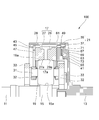
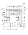
- FIG. 18 is an enlarged cross-sectional view of a main part of the friction roller type speed reducer 300 of the second configuration example
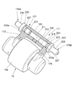
- FIG. 19 is a partial cross-sectional perspective view of the swing holder 32 that supports the intermediate roller 19.
- the intermediate roller 19 includes a roller main body 19A having an outer peripheral surface 19a serving as a traction surface, and a pair of axially extending ends 19b, 19b at both ends of the roller main body 19A. And support shafts 31, 31.
- the intermediate roller 19 is a solid body in which a roller body 19A and a pair of support shafts 31, 31 are integrally formed.
- the pair of support shafts 31 and 31 are supported by the arm portions 173 and 175 of the swing holder 32 via the needle bearings 22, respectively.
- swing holder 32 two parts, a main body portion 177 having one arm portion 173 and the other arm portion 175, are joined using screws provided on the swing shaft 179B.
- the main body portion 177 includes an arm portion 173 and a base portion 181 to which the base end side of the arm portion 173 is connected.
- a swing shaft hole, which will be described later, through which the swing shafts 179A and 179B are inserted is formed inside the base portion 181.
- the arm portions 173 and 175 are each formed with a shaft hole 182 that accommodates the support shaft 31 of the intermediate roller 19 facing each tip side.
- the shaft hole 182 is a blind hole with one end closed, and the support shaft 31 of the intermediate roller 19 is supported by the shaft hole 182 via the needle bearing 22.
- the needle bearing 22 is a shell type needle bearing having a needle roller 183, a cage 185, and an outer ring 187, or a solid type needle bearing.
- the needle bearing 22 supports the intermediate roller 19 so as to be rotatable and movable in the axial direction.
- the swing holder 32 configured as described above has support shafts 31 and 31 arranged in parallel with the input shaft 11.
- the swing holder 32 is supported by the carrier 33 so that the intermediate roller 19 can move (swing) in the radial direction of the input shaft 11.
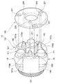
- FIG. 20 is an exploded perspective view of the carrier 33.
- the carrier 33 includes a carrier body 191 and an annular connection plate 193 that is fixed to one end side of the carrier body 191.
- the carrier main body 191 has a ring-shaped bottom portion 195 and column portions 197 erected at a plurality of locations (three locations in the illustrated example) at equal intervals in the circumferential direction of the bottom portion 195.
- the connecting plate 193 is fixed to the tip end portion 197a of the column portion 197.
- the column part 197 and the connecting plate 193 are formed with bolt insertion holes 199 and 201 penetrating along the axial direction.
- the carrier body 191 is fixed to a motor body (not shown) by a fastening member such as a bolt inserted into the bolt insertion holes 199 and 201.
- a swing holder 32 that supports the intermediate roller 19 is disposed between the column portions 197 arranged in the circumferential direction.
- One swinging shaft 179B of the swinging holder 32 is inserted into a shaft hole 205 formed in the connecting plate 193.
- the other swing shaft (swing shaft 179A in FIG. 19) is inserted into a shaft hole (not shown) formed in the bottom 195 of the carrier body 191.
- the intermediate roller 19 is pivotally supported about the pivot shafts 179 and 179B so that the intermediate roller 19 can protrude and retract in the radial direction of the carrier 33.
- the swing holder 32 is provided independently for each of the plurality of intermediate rollers 19, and one intermediate roller 19 is supported by each swing holder 32.
- the friction roller type speed reducer 300 of this configuration has the loading cam mechanism 23 disposed only on the outer end face side that is the outer side in the axial direction of one of the ring roller elements 27 and 29. .
- the loading cam mechanism 23 displaces the movable ring roller element 29 toward the fixed ring roller element 27 according to the rotational torque from the input shaft 11. Then, an axial force acts on the intermediate roller 19.
- the intermediate roller 19 receives the axial force and slides in the axial direction. This sliding operation is realized by the needle bearing 22.
- the needle bearing 22 does not hinder the axial displacement of the intermediate roller 19 and enables a smooth sliding operation with low resistance.
- the intermediate roller 19 slides smoothly and suppresses the occurrence of wear and friction. Thereby, it can prevent that the surface pressure of each traction surface becomes imbalanced.
- the intermediate roller 19 is supported by the swing holder 32 so as to be movable in the axial direction.
- a gap ⁇ is formed between one and the other end surface 19b of the roller body 19A and the holder inner surface of the swing holder 32, that is, between the end surface 19b and the inner surfaces facing the pair of arm portions 173 and 175, respectively. Is done. These gaps ⁇ enable the intermediate roller 19 to move in the axial direction.
- FIG. 21 shows a partial cross-sectional perspective view of the swing holder 32 that supports the intermediate roller 19.
- the swing holder 32 has a main body portion 177 and an arm portion 175 joined by a swing shaft 179B.
- the base 181 of the swing holder 171 is formed with a swing shaft hole 211 to which the swing shafts 179A and 179B are attached.
- the base portion 181 includes a female screw portion 213 and a large diameter portion 215 in the swing shaft hole 211.
- the arm portion 175 is formed with a swing shaft hole 217 having the same diameter as the large diameter portion 215.
- the swing shafts 179B inserted into the swing shaft holes 211 and 217 are connected to the male screw portion 219 for coupling, the positioning portion 221, the flange portion 223, and the carrier 189 in order from the insertion tip side to the base portion 181. And a locking shaft 225 inserted into the moving shaft hole 211.
- the swing shaft 179B is inserted into the swing shaft hole 211 of the base portion 181 through the swing shaft hole 217 of the arm portion 175, and the male screw portion 219 at the tip is screwed into the female screw portion 213.
- the swing shaft 179B is fixed in a state where one end surface of the flange portion 223 abuts on the arm portion 175 and both are tightened by screwing.
- the base portion 181 and the arm portion 175 are positioned by inserting the positioning portion 221 into the large diameter portion 215 and the swing shaft hole 217. That is, the positioning portion 221 of the swing shaft 179B, the large diameter portion 215, and the swing shaft hole 217 have an inlay connection function.
- the rocking shaft 179A has a positioning portion 231, a flange portion 233, and a locking shaft 235 inserted into the shaft hole of the carrier 189 in this order from the insertion tip side to the base portion 181.
- An annular groove 237 serving as an oil passage described later is formed in a part of the positioning portion 231.
- the generation of an axial load due to the skew of the needle bearing 22 is reduced. Furthermore, since both sides of the intermediate roller 19 are supported, the support span is wide compared to the case where the intermediate roller 19 is supported on the inner periphery. As a result, relative skew between the needle bearing 22 and the intermediate roller 19 is less likely to occur.
- the intermediate roller 19 has a solid structure in which the roller body 19A and the support shafts 31 and 31 are integrated, rigidity is increased. Thereby, the amount of elastic deformation due to the normal force is smaller than that of the hollow structure, and the axial displacement of the intermediate roller 19 due to the axial thrust from the movable ring roller element 29 can be suppressed to a small value.
- the balance of the intermediate roller 19 can be easily corrected, abnormal vibration due to the deviation of the center of gravity can be prevented, and stable high-speed rotation can be realized. Further, the intermediate roller 19 has a higher resonance frequency due to an improvement in rigidity, which also reduces the occurrence of abnormal vibration due to resonance. The same effect as that of the sun roller 15 can be said for the above-described effect of the intermediate roller 19 having a solid structure.
- FIG. 22 is a partial sectional perspective view of the carrier 33 on which the swing holder 32 is supported.
- One end surface 233a of the flange portion 233 of the swing shaft 179A functions as a seating surface when the swing shaft 179A is fastened.
- the other end surface 233 b is a contact surface with the connecting plate 193 of the carrier 33.
- a sliding bush 241 is loaded into the shaft hole 205 of the connecting plate 193, and the locking shaft 235 of the swing shaft 179 ⁇ / b> A is inserted into the sliding bush 241.
- the locking shaft 235 has a washer 243 interposed between the flange portion 233 and the connecting plate 193.
- the flange portion 223 of the swing shaft 179B has one end surface 223a that functions as a seating surface when the swing shaft 179B is fastened.
- the other end surface 223b is a contact surface of the carrier 33 with the carrier body 191.
- a sliding bush 241 and a washer 243 are interposed in the locking shafts 225 and 235 of the swing shafts 179A and 179B, respectively.
- the intermediate roller 19 is an indispensable member because it is driven to rotate at high speed.
- the oil supply position may deviate from the target position due to the axial displacement of the intermediate roller 19. Therefore, it is desirable to provide a separate oil supply passage to the intermediate roller 19 and reliably supply oil to the intermediate roller 19, but the oil passage structure corresponding to the axial movement becomes complicated, and the manufacturing cost and maintenance cost of the apparatus itself It becomes a factor to increase.
- the intermediate roller 19 is supported by the needle bearing 22 so as to be movable in the axial direction. Even in this configuration, the lubricating oil can be supplied to an appropriate supply position with an appropriate amount of oil without complicating the supply path of the lubricating oil.
- FIG. 23 is a partially sectional perspective view of the swing holder 32 cut along a plane including the central axes of the swing shafts 179A and 179B.
- a lubricating oil supply passage 247 (see FIG. 22) formed in the carrier 33 supplies lubricating oil to the swing shaft 179B.
- the swing shafts 179A and 179B are formed with shaft holes 251 and 253 serving as oil passages in the inner diameter portion.
- Lubricating oil is supplied to the oil passages 255 and 257 formed in the arm portions 173 and 175 through the shaft holes 251 and 253.
- a part of the lubricating oil supplied to the shaft hole 251 of the swing shaft 179B is supplied through an opening hole (not shown) into the annular groove 227 formed in a part of the positioning portion 221.
- lubricating oil is also supplied into the annular groove 237 formed in the positioning portion 231 of the swing shaft 179A.
- Lubricating oil in the annular groove 227 is sent to the shaft hole 182 that supports the needle bearing 22 through an oil passage 255 formed in the arm portion 175 (arrow D1 in the figure).
- the lubricating oil in the annular groove 237 is sent to the shaft hole 182 on the arm portion 173 side through the oil passage 257 formed in the arm portion 173.
- FIG. 24 is a perspective view of the arm portion 175 alone
- FIG. 25 is a cross-sectional perspective view taken along the line IIXV-IIXV shown in FIG.
- the arm portion 175 includes a swing shaft hole 217 into which the swing shaft 179B (see FIG. 23) is inserted, a shaft hole 182 that supports the needle bearing 22 (see FIG. 23), and a shaft hole 182 from the swing shaft hole 217. And an oil passage 255 communicating with each other.
- the oil passage 255 is a straight hole drilled through the hole 259.
- An oil groove 261 is formed on the inner peripheral surface of the shaft hole 182 along the axis of the shaft hole 182.
- the oil groove 261 is formed from the bottom side of the shaft hole 182 to the opening of the oil passage 255 and communicates with the oil passage 255.
- a stop plug 263 (see FIG. 23) is press-fitted into a portion where the oil groove 261 is formed in the bottom portion of the shaft hole 182 so that the lubricating oil does not leak.
- the lubricating oil supplied through the oil passage 255 shown in FIG. 23 is supplied to the bottom of the shaft hole 182 through an oil passage formed between the oil groove 261 in the shaft hole 182 and the outer peripheral surface of the outer ring 187 ( Arrow D2) in the figure.
- the lubricating oil that has reached the bottom of the shaft hole 182 is directed radially inward of the needle bearing 22 through the end face of the outer ring 187 (arrow D3 in the figure) and passes through the internal space of the needle bearing 22 on the support shaft 31 (in the figure). Arrow D4).
- the lubricating oil is supplied along a flow corresponding to the flow indicated by D1 to D4.
- the oil passages such as the oil passages 255 and 257, the hole 259, and the oil groove 261 are formed by electric discharge machining or machining.
- the oil passage 255 and the hole 259 and the oil passage 257 and the hole 259 are formed from the distal end side of the arm portions 173 and 175 toward the proximal end side of the swing center.
- the oil groove 261 is formed from the bottom outer side of the shaft hole 182 toward the opening of the oil passage 255 (the same applies to the arm portion 173 side). Since the holes 259 and 259 at the tips of the arm portions 173 and 175 opened when the oil passages 255 and 257 are formed are closed by the outer ring 187 of the needle bearing 22, it is not necessary to incorporate a stopper plug.
- the supply oil path of the lubricating oil supplied to the intermediate roller 19 is not complicated, and even when the intermediate roller 19 moves in the axial direction, the proper supply position is set to the proper position.
- An oil amount of lubricating oil can be supplied. Further, an appropriate amount of lubricating oil is always supplied to the needle bearing 22, and the intermediate roller 19 can be smoothly rotated.
- the present invention is not limited to the above-described embodiments, and those skilled in the art will be able to combine the configurations of the embodiments with each other, based on the description of the specification and well-known techniques. Modifications and applications are also within the scope of the present invention and are within the scope of seeking protection.
Landscapes
- Engineering & Computer Science (AREA)
- General Engineering & Computer Science (AREA)
- Mechanical Engineering (AREA)
- Friction Gearing (AREA)
Abstract
摩擦ローラ式減速機は、入力軸と同心に配置されるサンローラと、固定リングローラ素子及び可動リングローラ素子を有するリングローラと、サンローラの外周面とリングローラの内周面に転がり接触する複数の中間ローラと、リングローラと出力軸とを連結する連結部と、カムリングを有し各転がり接触面の接触面圧を変更するローディングカム機構とを備える。サンローラの外周面は、軸断面の外縁形状が単一円弧状の凹曲線となる凹曲面であり、中間ローラの外周面は、軸断面の外縁形状が単一円弧状の凸曲線となる凸曲面である。
Description
本発明は、摩擦ローラ式減速機に関する。
近年普及し始めている電気自動車の利便性を向上させるべく、充電1回当りの走行可能距離を長くする為に、電動モータの効率向上が強く要望されている。電動モータの効率向上には、高速回転する小型の電動モータを使用し、モータ出力軸の回転を減速してから車両の駆動輪に伝達することが望ましい。この場合、モータ出力軸に接続される減速機は、運転速度が非常に速くなり、振動や騒音を発しやすくなる。そこで、運転時の振動や騒音を抑える為に、摩擦ローラ式減速機を使用することが考えられている。従来の摩擦ローラ式減速機としては、例えば特許文献1、2に記載されたものが知られている。
特許文献1に記載された摩擦ローラ式減速機500は、図26に示すように、入力軸に接続されたサンローラ511と、一端に保持筒513を有する出力軸512と、1対のリングローラ素子514A,514Bからなるリングローラ515と、リングローラ515の内周面とサンローラ511の外周面との間の環状空間内に配置された複数個の中間ローラ516と、リングローラ素子514Aの側面に配置された面圧付与装置517と、備える。
サンローラ511の外周面は、軸方向に関して外径が変化しない円筒面である。リングローラ素子514A,514Bの内周面は、リングローラ素子514A,514Bの互いに対向する面である先端面側ほど内径が大きくなる方向に傾斜した、部分円錐面である。また、中間ローラ516の外周面は、軸方向中間部が軸方向に関して外径が変化しない円筒面であり、軸方向両端部が、中間ローラ516の軸方向両端面に向かうほど外径が小さくなる方向に傾斜した、部分円錐面となっている。そして、サンローラ511の回転を、各中間ローラ516を介してリングローラ515に伝達し、このリングローラ515の回転を、保持筒513を介して出力軸512から取り出すようにしている。
上記構成では、面圧付与装置517をリングローラ515側に設けている。これにより、サンローラ511側に設けた構成と比較して、入力軸の回転中心から、リングローラ515の内周面、及び各中間ローラ516の外周面の各転がり接触部までの回転半径が長くしている。よって、転がり接触部における接触領域(接触楕円)の軸方向両端の半径距離差を、半径距離に対して小さくでき、接触楕円内で発生する周速差を小さく抑えることができる。
特許文献2に記載された摩擦ローラ式減速機は、サンローラと、サンローラと同心に配置されるリングローラと、サンローラの外周面とリングローラとの内周面との間で、回転自在に支持される複数の中間ローラと、を備える。サンローラは、一対のサンローラ素子からなり、ローディングカム機構により、伝達トルクに応じて一方のサンローラ素子を他方のサンローラ素子に対して軸方向へ接近又は離反させ、サンローラ素子、中間ローラ、リングローラの各面圧を変更している。
しかしながら、上記特許文献1の構成では、中間ローラ516の軸方向両端部の外周面(部分円錐面)の傾斜角度は、リングローラ素子514A,514Bの内周面(部分円錐面)の傾斜角度と等しくする必要がある。そのため、双方の傾斜角度を複合的に調整しなければならず、加工コストが嵩む問題がある。
また、中間ローラ516の軸方向両端部の外周面とリングローラ素子514A,514Bの内周面との滑りを低減するためには、中間ローラ516の外周面を円弧形状とすることが考えられる。こうすることで、中間ローラ116とリングローラ素子514A,514Bとの転がり接触部を、接触面積が小さい点接触状態にできる。しかし、中間ローラ516の外周面を円弧形状とすると、円筒面であるサンローラ511の外周面との接触部が点接触となり、接触面圧が高くなる。更に、中間ローラ516は、リングローラ515と2箇所で接触するのに対して、サンローラ511とは1箇所で接触するので、接触面圧が増大する傾向にある。そのため、サンローラ511と中間ローラ516との接触面圧の増大は、高速回転するサンローラ511の耐久寿命に影響を及ぼしかねない。
特許文献2の構成においては、一対のローディングカム機構を設けて一対のサンローラ素子を相互に接近又は離反させるため、中間ローラの軸方向に関する中心位置が一定に保たれる。しかし、減速機の部品点数削減、小型化、組立性の向上の観点から、ローディングカム機構を片側にのみ設けた構成も採用される。その場合、一対のサンローラ素子は、一方が固定側、他方が可動側となり、可動サンローラ素子のみが軸方向に移動する。可動サンローラ素子のみ軸方向に移動すると、各サンローラ素子と転がり接触する中間ローラには、軸方向力が作用する。しかし、一般に中間ローラは、軸方向移動を想定せず軸支される構造であるため、発生した軸方向力によって、中間ローラのトラクション部に余分な摩擦力が生じる。この摩擦力がトラクション部に摩耗を引き起こす原因となる。このことは、サンローラに限らず、リングローラが軸方向に分割された一対のリングローラ素子を有する構成の場合でも同様である。
上記摩耗を回避する手段としては、遊星歯車減速機等においては、歯車(ローラ)の内径側にニードル軸受を配置し、回転可能、且つ軸方向移動可能に支持するのが一般的である。
ところが、摩擦ローラ式の場合、ローラに負荷される法線力により、ローラが径方向に弾性変形するという特有の問題を有している。つまり、上記構成の場合、伝達トルクの増加に伴って中間ローラに負荷される法線力が増加した際に、ニードル軸受の内部すきまが小さくなる。すると、ニードル軸受の初期すきまの設定によっては、内部すきまが負すきまになることがある。ニードル軸受が負すきまになると、トラクション面の接触面圧が設計値より大きくなり、軸受の耐久寿命が短くなる。
また、ニードル軸受は、回転軸と内外輪の軌道面との間に相対的な傾き(スキュー)が発生する。このスキューは、軸受内部に滑りによる軸方向荷重を生じさせる。一般的に、スキューにより生じる軸方向荷重は、転動体荷重の総和と相関を有する。つまり、中間ローラの内径部にニードル軸受を配置した構成では、軸受内部すきまが負になりやすく、スキューによる軸方向荷重が大きくなる。スキューによる軸力がローラに生じると、トラクション面の面圧が高くなり、減速機の寿命に影響を及ぼすことになる。
また、ニードル軸受は、回転軸と内外輪の軌道面との間に相対的な傾き(スキュー)が発生する。このスキューは、軸受内部に滑りによる軸方向荷重を生じさせる。一般的に、スキューにより生じる軸方向荷重は、転動体荷重の総和と相関を有する。つまり、中間ローラの内径部にニードル軸受を配置した構成では、軸受内部すきまが負になりやすく、スキューによる軸方向荷重が大きくなる。スキューによる軸力がローラに生じると、トラクション面の面圧が高くなり、減速機の寿命に影響を及ぼすことになる。
本発明は、前述した課題に鑑みてなされたものであり、その第1の目的は、加工コストの増加やサンローラの耐久性低下を招くことなく、中間ローラとリングローラとの間の滑り損失を低減させてトルク伝達効率の高い摩擦ローラ式減速機を提供することにある。
また、第2の目的は、伝達トルクが増大した場合でも、中間ローラの弾性変形の影響を受けることなく、ローディングによるローラの変位を円滑にし、摩擦や摩耗の発生を抑制できる摩擦ローラ式減速機を提供することにある。
また、第2の目的は、伝達トルクが増大した場合でも、中間ローラの弾性変形の影響を受けることなく、ローディングによるローラの変位を円滑にし、摩擦や摩耗の発生を抑制できる摩擦ローラ式減速機を提供することにある。
本発明は、下記構成からなる。
(1) 入力軸と同心に配置されるサンローラと、前記サンローラの外周側に前記サンローラと同心に配置されるリングローラと、前記サンローラの外周面と前記リングローラの内周面との間で、前記入力軸と平行な自転軸を中心として回転自在に支持され、前記サンローラの外周面と前記リングローラの内周面に転がり接触する複数の中間ローラと、前記リングローラと出力軸とを連結する連結部と、各ローラの転がり接触面の接触面圧を変更するローディングカム機構と、を備える摩擦ローラ式減速機であって、
前記リングローラは、前記入力軸の軸方向に並設された一対のローラ素子からなり、
前記一対のローラ素子の少なくとも一方は、前記軸方向に移動自在な可動ローラ素子であり、
前記ローディングカム機構は、前記可動ローラ素子の前記軸方向の外側端面側にのみ配置され、前記入力軸の回転トルクに応じて、前記可動ローラ素子を他方の前記ローラ素子に向けて変位させるものであり、
前記サンローラの外周面は、軸断面の外縁形状が単一円弧状の凹曲線となる凹曲面であり、
前記中間ローラの外周面は、軸断面の外縁形状が単一円弧状の凸曲線となる凸曲面である摩擦ローラ式減速機。
(2) 前記ローディングカム機構は、該可動ローラ素子の外側端面の円周方向に沿った複数箇所に設けられた第1カム溝と、前記可動ローラ素子の外側端面に対面配置され前記第1カム溝に対応する複数箇所に第2カム溝が設けられたカムリングと、前記第1カム溝と前記第2カム溝との間にそれぞれ挟持される複数の転動体と、を有し、前記第1カム溝と前記第2カム溝は、それぞれ前記軸方向の深さが円周方向に沿って漸次変化して、カム溝の円周方向端部に向かうに従って浅くなる形状にされている(1)の摩擦ローラ式減速機。
(3) 前記中間ローラと、前記サンローラと、前記リングローラのうち、
いずれか一つのローラは、軸回転可能で且つ軸方向変位不能に支持され、
前記いずれか一つのローラ以外のローラは、軸回転可能で且つ軸方向変位可能に支持される(1)又は(2)の摩擦ローラ式減速機。
(4) 複数の前記中間ローラのそれぞれに設けられ、前記自転軸を支持するホルダを備え、
前記中間ローラは、前記サンローラの外周面と前記リングローラの内周面に転がり接触するトラクション面を外周面に有するローラ本体の両端部に、前記自転軸が延設され、
前記ホルダは、ホルダ内面と前記ローラ本体の端面との間に、前記中間ローラが前記軸方向に移動可能な隙間を有し、前記自転軸をニードル軸受を介して回転自在、且つ前記軸方向へ移動自在に支持する(3)の摩擦ローラ式減速機。
本発明の摩擦ローラ式減速機によれば、リングローラ側に配置されたローディングカム機構を備え、サンローラの外周面は、軸断面の外縁形状が単一円弧状の凹曲線となる凹曲面であり、中間ローラの外周面は、軸断面の外縁形状が単一円弧状の凸曲線となる凸曲面であるので、加工コストを増加させることなく、中間ローラとリングローラとの転がり接触部における接触領域の軸方向両端と中央部の周速の差を小さくできる。これにより、摩擦損失を低減させ、トルク伝達効率を向上させることができる。また、中間ローラの外周面とサンローラの外周面との転がり接触部における接触面圧を低減させてサンローラの耐久性を向上させることができる。
また、本発明によれば、中間ローラの両端部に延設された自転軸がニードル軸受を介してホルダに支持されるため、中間ローラを回転自在、且つ軸方向に移動自在に支持できる。この構成により、伝達トルクに応じて中間ローラに法線力が負荷されても、ニードル軸受の内部すきまは変化しないため、軸受の耐久寿命を向上できる。また、中間ローラの支持スパンが広がり、スキューが生じ難くなる。
また、本発明によれば、中間ローラの両端部に延設された自転軸がニードル軸受を介してホルダに支持されるため、中間ローラを回転自在、且つ軸方向に移動自在に支持できる。この構成により、伝達トルクに応じて中間ローラに法線力が負荷されても、ニードル軸受の内部すきまは変化しないため、軸受の耐久寿命を向上できる。また、中間ローラの支持スパンが広がり、スキューが生じ難くなる。
以下、本発明の実施形態について、図面を参照して詳細に説明する。
[第1構成例]
まず、発明の実施形態を説明する摩擦ローラ式減速機の第1構成例を説明する。
<摩擦ローラ式減速機の構成>
図1は第1構成例の摩擦ローラ式減速機の一部断面斜視図、図2は摩擦ローラ式減速機の要部拡大断面図である。図1及び図2に示すように、摩擦ローラ式減速機100は、入力軸11と同心に配置されるサンローラ15と、リングローラ17と、複数の中間ローラ19と、リングローラ17と出力軸13とを連結する連結部21と、ローディングカム機構23と、を備える。
[第1構成例]
まず、発明の実施形態を説明する摩擦ローラ式減速機の第1構成例を説明する。
<摩擦ローラ式減速機の構成>
図1は第1構成例の摩擦ローラ式減速機の一部断面斜視図、図2は摩擦ローラ式減速機の要部拡大断面図である。図1及び図2に示すように、摩擦ローラ式減速機100は、入力軸11と同心に配置されるサンローラ15と、リングローラ17と、複数の中間ローラ19と、リングローラ17と出力軸13とを連結する連結部21と、ローディングカム機構23と、を備える。
サンローラ15は、入力軸11の一端に、入力軸11と同心に一体形成された中実構造のローラである。サンローラ15の外周面15aは、軸断面の外縁形状が単一円弧状の凹曲線となる凹曲面に形成されている。
リングローラ17は、軸方向に並設された一対のリングローラ素子であって、固定リングローラ素子27と、軸方向に移動自在な可動リングローラ素子29とを有する。これら各リングローラ素子27,29は、カップ状の連結部21の内側に収容された状態でサンローラ15の外周側にサンローラ15と同心に配置される。
固定リングローラ素子27及び可動リングローラ素子29は、内周面27a,29aが、環状の傾斜面となっている。これら傾斜面は、各リングローラ素子27,29同士の互いに対向する対向側端面33,35から軸方向反対側の外側端面137,139に向かうに従って、中間ローラ19の自転軸中心までの距離が短くなる傾斜面である。つまり、外側端面137,139に向かうに従って内径が小さくなる傾斜面である。これらの傾斜面は、中間ローラ19が転動する転がり接触面となる。内周面27a,29aは、上記傾斜面に限らず、軸断面の外縁形状が単一円弧状の凹曲線となる凹曲面であってもよい。
複数の中間ローラ19は、それぞれニードル軸受22を介して支持軸(自転軸)31に回動自在、且つ軸方向に変位可能に支持され、サンローラ15の外周面15aとリングローラ17の内周面17aとの間に配置される。支持軸31の両端は、揺動ホルダ32に支持される。また、揺動ホルダ32は、中間ローラ19を入力軸11の径方向に移動(揺動)可能にキャリア33に支持される。キャリア33は、図示しないモータ本体に締結部材によって固定される。
各中間ローラ19の外周面19aは、軸断面の外縁形状が単一円弧状の凸曲線となる凸曲面であり、それぞれサンローラ15の外周面15aとリングローラ17の内周面17aに転がり接触する。
連結部21は、略円板状に形成され中心部が出力軸13に連結される基端部37と、基端部37の外周縁から軸方向に延設されて内径側にリングローラ17が保持される円筒状のローラ保持部39と、を有する。
ローラ保持部39の内部には、基端部37側から、波板状の予圧スプリング67、カムリング49、転動体である玉51、可動リングローラ素子29、固定リングローラ素子27、止め輪47がこの順で挿入され、これら各部材がローラ保持部39に組み付けられる。
ローラ保持部39の内周部には、複数の凹溝43が軸方向に沿って形成される。また、ローラ保持部39の基端部37とは反対側の端部の内周部には、円周方向にリング溝45(図1参照)が形成される。
凹溝43は、固定リングローラ素子27の外周部の複数箇所に形成された、径方向外側に突出する複数の突起28を収容する。固定リングローラ素子27の突起28は、ローラ保持部39の凹溝43に回転方向のがたつきがない状態で係合し、ローラ保持部39とリングローラ17との回転トルクの伝達を可能にする。
リング溝45は、止め輪47が嵌入される。止め輪47は、固定リングローラ素子27の軸方向位置を規制し、固定リングローラ素子27をローラ保持部39に固定する。
連結部21の基端部37は、例えば、旋盤加工等の切削加工により形成され、ローラ保持部39は、プレス成形等の塑性加工により形成される。これら基端部37とローラ保持部39とを単体で形成した後、双方を接合することで、低コストで高精度に軸芯を一致させる構成にできる。また、基端部37とローラ保持部39は、ビーム溶接で接合処理される。これにより、狭幅のビードで、しかも短時間で加熱接合でき、熱歪を最小限に抑えて芯ずれの発生が抑制可能となる。
カムリング49は、その外周部から径方向外側に突出する複数の突起61を有する。カムリング49の突起61は、固定リングローラ素子27の突起28と同様に、それぞれローラ保持部39の凹溝43に係合する。
カムリング49は、出力軸側の外側端面に、外径側の一部を環状に切欠いた切欠き部63が形成され、この切欠き部63に予圧スプリング67が装着される。
上記サンローラ15は、高速回転するために、微小な重心のずれがあると異常振動の振動源となる虞がある。しかし、本構成のサンローラ15は、入力軸11と一体形成されるので、容易にバランス修正が可能であり、振動の発生を低減できる。また、サンローラ15は、剛性が高く、高い共振周波数を有するので、共振による異常振動の発生が低減する。更に、サンローラ15を中実構造とすることで、後述する荷重が負荷された際のサンローラ15の弾性変形量が小さくなる。これにより、中間ローラ19とリングローラ17の軸方向変位量が小さくなり、転がり接触面の接触状態を設計通りの良好な状態に維持できる。
<ローディングカム機構>
次に、ローディングカム機構について説明する。
図1に示す可動リングローラ素子29と、カムリング49と、転動体である玉51は、ローディングカム機構23を構成する。このローディングカム機構23は、サンローラ15、リングローラ17、及び中間ローラ19の各転がり接触面の接触面圧を変更する。
次に、ローディングカム機構について説明する。
図1に示す可動リングローラ素子29と、カムリング49と、転動体である玉51は、ローディングカム機構23を構成する。このローディングカム機構23は、サンローラ15、リングローラ17、及び中間ローラ19の各転がり接触面の接触面圧を変更する。
可動リングローラ素子29の外側端面には、図3及び図4に示すように、円周方向に沿って複数(図示例では3箇所)の第1カム溝53が形成される。カムリング49は、第1カム溝53に対面配置され、第1カム溝53に対応する円周方向位置に、複数(図示例では3箇所)の第2カム溝55が形成される。これら第1カム溝53と第2カム溝55との間には、それぞれ玉51が挟持される。
第1カム溝53及び第2カム溝55は、軸方向の溝深さが、円周方向に関して中央部で最も深く、円周方向に沿って漸次変化して、カム溝53,55の円周方向端部に向かうに従って浅くなる形状にされる。
入力軸11が停止している状態では、図4(A)に示すように、各玉51は各カム溝の最も深くなった部分に位置する。この状態では、カムリング49は、予圧スプリング67の弾性力により、可動リングローラ素子29側に向けて押圧されている。
入力軸11が回転駆動されると、図4(B)に示すように、各玉51が各カム溝53,55の浅くなった部分に移動する。これにより、可動リングローラ素子29を固定リングローラ素子27に向けて押圧する軸方向推力が発生する。ローディングカム機構23が発生する軸方向推力は、固定リングローラ素子27と可動リングローラ素子29との間隔を縮める。すると、リングローラ17の内周面17aと、各中間ローラ19の外周面19aとの転がり接触部における接触面圧が上昇する。これと共に、各中間ローラ19の外周面19aとサンローラ15の外周面15aとの転がり接触部の接触面圧も上昇する。その結果、入力軸11と出力軸13との間に存在する複数の転がり接触部の接触面圧が上昇する。この接触面圧は、入力軸11と出力軸13との間で伝達するトルクが大きくなるほど上昇する。
また、ローディングカム機構23が発生する軸方向推力は、リングローラ17等のトラクション部品に弾性変形や各接触点の弾性変形を生じさせる。また、中間ローラ19は、可動リングローラ素子29の軸方向変位に伴って、固定リングローラ素子27側に軸方向変位する。
<各部材の軸心を一致させる構造>
図2に示すように、連結部21の基端部37における入力軸11側の内側面には、出力軸13と平行な内周面を有する円環状の第1段付部41が形成される。
図2に示すように、連結部21の基端部37における入力軸11側の内側面には、出力軸13と平行な内周面を有する円環状の第1段付部41が形成される。
また、カムリング49の外側端面には、リング中心と同心に形成され、連結部21の基端部37の第1段付部41と軸方向に沿って係合する外周面を有する第2段付部65が、軸方向に突出して形成される。
カムリング49と連結部21とは、第1段付部41と第2段付部65とが嵌合することによって高精度に軸心が一致する。これにより、可動リングローラ素子29もカムリング49を介して軸心位置が正確に位置決めされる。また、固定リングローラ素子27は、中間ローラ19によって径方向に位置決めされる。中間ローラ19は、入力軸11と同心のサンローラ15によって径方向に位置決めされ、入力軸11と出力軸13とは同心に配置される。これにより、サンローラ15、中間ローラ19、リングローラ17、及びカムリング49は、各軸心が正確に一致した状態となっている。
また、切欠き部63によって連結部21の基端部37の内側面69との間に形成された環状空間71には、予圧スプリング67が配置される。カムリング49は、この予圧スプリング67によって、基端部37とは軸方向反対側に付勢された状態で、第2段付部65が基端部37の第1段付部41に嵌合する。この嵌合長は、予圧スプリング67の弾性変形代より長くされている。これにより、カムリング49を基端部37に組み付ける際に、予圧スプリング67がカムリング49と基端部37との間から外れず、減速機の組立性が向上する。
<中間ローラの軸方向位置のオフセット>
次に、中間ローラ19の軸方向位置のオフセットについて説明する。
図5に無負荷状態で中間ローラ19がオフセットされた状態を示す。無負荷状態では、中間ローラ19の外周面の円弧状凸曲面の中心は、サンローラ15の外周面の円弧状凹曲面の中心に対して軸方向に所定量オフセットされる。
次に、中間ローラ19の軸方向位置のオフセットについて説明する。
図5に無負荷状態で中間ローラ19がオフセットされた状態を示す。無負荷状態では、中間ローラ19の外周面の円弧状凸曲面の中心は、サンローラ15の外周面の円弧状凹曲面の中心に対して軸方向に所定量オフセットされる。
入力軸11が停止され、予圧スプリング67の弾性力のみによりカムリング49が押圧されている無負荷状態(図4(A)の状態)においては、中間ローラ19の外周面19aである円弧状凸曲面の中心C2は、サンローラ15の外周面15aである円弧状凹曲面の中心C1に対して、カムリング49側に軸方向に沿った所定量Lだけオフセットされている。また、中間ローラ19と転がり接触するリングローラ17の中心も同様に、所定量Lだけオフセットされている。なお、このオフセット量Lについての詳細は後述する。
ここで、入力軸11が回転駆動されると(図4(B)の状態)、リングローラ17等のトラクション部品の弾性変形や各接触点の弾性変形により、中間ローラ19も可動リングローラ素子29の移動に伴って、固定リングローラ素子27側に軸方向変位する。これにより、中間ローラ19の外周面19aの中心C2が、サンローラ15の外周面15aの中心C1に接近する。この結果、オフセット量Lが小さくなり、中間ローラ19の円弧状凸曲面と、サンローラ15の円弧状凹曲面との曲面同士が一致する方向に変位する。なお、中間ローラ19の軸方向変位量は、可動リングローラ素子29の軸方向変位量の略1/2である。
また、カムリング49には押圧力の反力が作用するので、カムリング49は予圧スプリング67を押し潰しながら押圧方向とは逆方向に移動して、第2段付部65の外側面73が、基端部37の内側面69に当接して、カムリング49の軸方向位置が規制される。
ローディングカム機構23が軸方向の推力を発生すると、固定リングローラ素子27と可動リングローラ素子29との間隔が縮まる。すると、固定リングローラ素子27と可動リングローラ素子29により構成されるリングローラ17の内周面17aと、各中間ローラ19の外周面19aとの転がり接触部における接触面圧が上昇する。この接触面圧の上昇に伴って、各中間ローラ19の外周面19aとサンローラ15の外周面15aとの転がり接触部の接触面圧も上昇する。その結果、入力軸11と出力軸13との間に存在する複数の転がり接触部の接触面圧が、入力軸11と出力軸13との間で伝達するトルクが大きくなるほど上昇する。
入力軸11が回転駆動された状態では、入力軸11の回転が、サンローラ15から各中間ローラ19に伝達される。そして、各中間ローラ19が支持軸31を中心として自転する。各中間ローラ19の自転によってリングローラ17が回転し、固定リングローラ素子27の突起28がローラ保持部39の凹溝43に係合することで、ローラ保持部39と接続される出力軸13が回転する。
このときの各転がり接触部の接触面圧は、入力軸11と出力軸13との間で伝達するトルクの大きさに応じた適正な面圧となる。よって、各転がり接触部で過大な滑りの発生や、各転がり接触部の接触面圧が過大になることに伴う転がり抵抗の増大が防止される。
また、入力軸11と出力軸13との間にトルクが伝達されている間、固定リングローラ素子27は、止め輪47に当接して軸方向位置が規制される。また、カムリング49は、第2段付部65の外側面73と基端部37の内側面69とが当接することで軸方向位置が規制される。つまり、突起28を有する固定リングローラ素子27、及び突起61を有するカムリング49は、凹溝43と係合して回転動力が伝達され、軸方向には実質的に変位しない。そのため、係合部で磨耗が生じることを防止できる。
ここで、上記オフセット量Lについて説明する。図7(A),(B)は電気自動車用駆動装置に摩擦ローラ式減速機を組み込むことによる効果を示す説明図であり、図8は中間ローラの軸方向移動量と伝達トルクとの関係を示すグラフである。
例えば、電気自動車の駆動源である電動モータの出力軸と、駆動輪に繋がるデファレンシャルギヤの入力部との間部分に、減速比の大きな動力伝達装置を設けた場合、電気自動車の駆動トルクTと走行速度Vとの関係は、図7(A)の実線Paの左半部と一点鎖線Pbとを連続させた特性になる。即ち、低速時の加速性能は優れているが、高速走行には不向きとなる。
これに対して、減速比の小さな動力伝達装置を設けた場合、駆動トルクTと走行速度Vとの関係は、図7(A)の二点鎖線Pcと実線Paの右半部とを連続させた特性になる。即ち、高速走行は可能になるが、低速時の加速性能が損なわれる。また、出力軸と入力部との間に変速機を設け、車速に応じてこの変速機の減速比を変えれば、実線Paの左半部と右半部とを連続させた特性が得られる。この特性は、図7(A)に破線Pdで示される同程度の出力を有するガソリンエンジン車の特性と略同等になる。
ところで、実際の車両走行においては、車両発進状態では低速、高トルク領域が使用されるものの、全般的に使用頻度が高い通常走行状態は、図7(A)に領域Wで示す中速から高速、低トルク領域が頻繁に使用される。この使用頻度が高い領域における平均的な駆動トルクをTaとする。
一方、本発明の摩擦ローラ式減速機100の出力軸13に出力される駆動トルクTと、中間ローラ19の軸方向移動量Sとは、図8に模式的に示すように、概ね比例関係にあることが知られている。
したがって、通常走行での使用頻度が高い領域の平均的なトルクTaを出力する中間ローラ19の軸方向移動量Sを、中間ローラ19の外周面19aの中心C2と、サンローラ15の外周面15aの中心C1とのオフセット量Lに設定しておけば、摩擦ローラ式減速機100の作動時間のうちの多くの時間が、オフセット量ゼロの状態、換言すれば、図6に示すように、サンローラ15の円弧状凹曲面の中心C1と、中間ローラ19の円弧状凸曲面の中心C2とが一致した状態となる。
これにより、摩擦ローラ式減速機100の作動時間のうちの多くの時間を、サンローラ15と中間ローラ19との転がり接触部の接触を良好な状態に維持でき、減速機の耐久性が向上する。また、サンローラ15と中間ローラ19との接触点になる接触楕円が、軸受の軸方向に対して傾かない状態が維持されるので、トルクの伝達効率が向上する。
図7(B)に示すように、出力軸と入力部との間に変速機を設けず、ガソリンエンジン車の特性と略同等に改良された動力伝達装置を用いる場合も同様である。即ち、実線Paで示す特性のうち、使用頻度が高い領域Wにおける平均的な駆動トルクをTaとする。このトルクTaを出力する中間ローラ19の軸方向移動量Sを、中間ローラ19の外周面19aの中心C2と、サンローラ15の外周面15aの中心C1とのオフセット量Lに設定する。これにより、上記同様の理由で転がり接触部の接触を良好な状態に維持でき、トルクの伝達効率を向上できる。
<摩擦ローラ式減速機による効果>
中間ローラ19の外周面19aは、円弧状凸曲面とされている。そのため、リングローラ17と中間ローラ19との接触状態が点接触となり、転がり接触部における滑り損失を低減できる。また、中間ローラ19の円弧状凸曲面のクラウニング半径を小さくできるため、中間ローラ19とリングローラ17の接触面等価半径を小さくして滑り損失を低減できる。
中間ローラ19の外周面19aは、円弧状凸曲面とされている。そのため、リングローラ17と中間ローラ19との接触状態が点接触となり、転がり接触部における滑り損失を低減できる。また、中間ローラ19の円弧状凸曲面のクラウニング半径を小さくできるため、中間ローラ19とリングローラ17の接触面等価半径を小さくして滑り損失を低減できる。
更に、サンローラ15の外周面15aは、円弧状凹曲面とされている。そのため、サンローラ15と中間ローラ19との接触は、円弧状凹曲面と円弧状凸曲面との組合せとなり、中間ローラ19の外周面19aとの転がり接触領域の面積が大きくなる。この結果、転がり接触領域の接触面圧が低下してサンローラ15の摩耗が抑制され、減速機の耐久性が向上する。
また、ローディングカム機構23は、リングローラ17側に設けてある。そのため、サンローラ15側に設けた構成と比較して、リングローラ17の回転中心から、リングローラ17の各内周面17aと、各中間ローラ19の外周面19aとの転がり接触部までの半径距離が長くなる。これにより、転がり接触領域(接触楕円)の両端における周速差を小さく抑えることができ、リングローラ17側の転がり接触部での摩擦損失が低減して、高効率でトルクを伝達できる。
<各部材の寸法>
本構成の摩擦ローラ式減速機100の具体的な一寸法例を以下に説明する。サンローラ15の外周面15aは、軸断面の外縁形状が単一円弧状の凹曲線となる円弧状凹曲面であり、その直径は30mmである。また、円弧状凹曲面の逆クラウニング半径は19mm以上であり、中間ローラ19のクラウニング半径の1.08倍以上となっている。中間ローラ19の外周面19aは、軸断面の外縁形状が単一円弧状の凸曲線となる円弧状凸曲面であり、その直径は50mmである。
本構成の摩擦ローラ式減速機100の具体的な一寸法例を以下に説明する。サンローラ15の外周面15aは、軸断面の外縁形状が単一円弧状の凹曲線となる円弧状凹曲面であり、その直径は30mmである。また、円弧状凹曲面の逆クラウニング半径は19mm以上であり、中間ローラ19のクラウニング半径の1.08倍以上となっている。中間ローラ19の外周面19aは、軸断面の外縁形状が単一円弧状の凸曲線となる円弧状凸曲面であり、その直径は50mmである。
サンローラ15の逆クラウニング半径19mmとは、図9に示すように、逆クラウニングの頂点P1からΔL(=1mm)オフセットした点P2の傾斜角θが3°になる寸法である。逆クラウニング半径を19mm以下に設定すると、中間ローラ19の変位によりサンローラ15と中間ローラ19との接触点に傾斜角が発生して滑り損失が大きくなり、トルク伝達効率が低下するので好ましくない。
例えば、サンローラ15の直径を30mm、中間ローラ19の直径を50mm、伝達接線力を1000Nとしたとき、傾斜角θが3°の場合のトルク伝達効率の低下は5%となる。このように、サンローラ15の逆クラウニング半径を19mm以下とすると、摩擦ローラ式減速機100のトルク伝達効率が著しく低下する。
サンローラ15の逆クラウニング半径と、中間ローラ19のクラウニング半径とが近いほど、転がり接触領域での接触楕円が大きくなり、耐久性が向上して有利となる。しかし、各クラウニング半径のばらつきによって、意図しない部位での接触が生じる可能性がある。したがって、サンローラ15の逆クラウニング半径と、中間ローラ19のクラウニング半径とを等しくするよりは、サンローラ15の逆クラウニング半径を中間ローラのクラウニング半径の1.08倍以上にすることが好ましい。
負荷運転時における中間ローラ19の軸方向変位量は、少ない方が摩擦ローラ式減速機100の性能が安定するため、軸方向変位量を2mm以内に抑えることが好ましい。また、リングローラ17の軸方向変位量は、中間ローラ19の軸方向変位量の略2倍であり、リングローラ17の軸方向変位量が極端に大きくなると、ローディングカム機構23から玉51が脱落する原因となる。
<ローディングカム機構におけるローラのスキューによる影響>
上記したローディングカム機構23を用い、伝達トルクに応じた法線力をローラに付勢する摩擦ローラ式減速機が多数提案されている。また、この減速機のローラに生じるスキューが、減速機のトルク伝達効率や、耐久性、周辺部品の設計に大きく影響を与えることも知られており、その対策についても各種の提案がなされている。
上記したローディングカム機構23を用い、伝達トルクに応じた法線力をローラに付勢する摩擦ローラ式減速機が多数提案されている。また、この減速機のローラに生じるスキューが、減速機のトルク伝達効率や、耐久性、周辺部品の設計に大きく影響を与えることも知られており、その対策についても各種の提案がなされている。
例えば、ローラにスキューが生じると、ローラ軸方向にスキュー力が発生し、各ローラの支持軸受にアキシアル荷重が作用する。このアキシアル荷重は、支持軸受の摩擦トルクや耐久寿命に影響を及ぼす。
更に、トラクション面に傾斜角を有した摩擦ローラ式減速機において、ローラのスキューが発生すると、スキュー力がトラクション面の法線力に変換される。そのため、トラクション面の接触面圧が伝達トルクに対して過大となり、トルク伝達効率の低下、耐久寿命の低下といった影響を及ぼす。また、場合によっては、減速機を破損に至らせる可能性を生じる虞がある。
そこで、上記したローラにスキューが発生した場合でも、スキュー力及びトラクション面の法線力を加速度的に増加させないようにすることが重要となる。以下に、上記法線力を発散させずに小さく収束できる条件について詳細に説明する。なお、以降の説明においては、上述した部材と同一の部材については、同一の符号を付与することで、その説明を簡単化、又は省略する。
図10は一対のローラを模式的に示す説明図、図11(A)は図10(A)の上方から見た平面図、図10(B)はローラR2の転走面を模式的に展開して示す説明図である。
図10に示す一対のローラR1,R2の一方が他方に回転駆動される場合、図11(A)に示すように、ローラR2に対してローラR1にスキュー(角度φ)が生じることがある。その際に、図11(B)に示すように、ローラR1はローラR2に対して、図中破線で示す軌道LOB(理想転走面)に沿った方向、即ち、ローラR2の円周方向から角度φだけ傾斜した方向に転がろうとする。
しかしながら、ローラR1は軸方向に位置が規制されているため、実際には、ローラR2の円周方向に沿った図中実線で示す軌道LR(実転走面)を滑りながら転がる。その際、ローラR1,R2間には、滑り率(:tanφ)に応じた軸方向の滑りSaが生じる。そのため、一対のローラR1,R2間の法線力に応じたトラクション力が、ローラR1,R2の軸方向に作用する。
このときのスキュー力Fskewは、トラクション係数μ、及び法線力Fcによって(1)式で表すことができる。

トラクション係数μは、トラクション面の滑り率と相関を有しており、一般的には、図12に示すような特性として知られている。スキュー力を考える場合、図12の横軸は上記した滑り率(:tanφ)に相当する。このことから、ローラのスキュー角φが大きいほど、トラクション係数μが高くなり、スキュー力Fskewが大きくなることが分かる。
次に、スキュー力Fskewと、トラクション面の法線力FCとの関係について説明する。
図13は、リングローラ17側をテーパ面、サンローラ15側を接触角を有さないトラクション面とした場合に、中間ローラ19とサンローラ15にスキューが生じた様子を示す説明図である。
図13は、リングローラ17側をテーパ面、サンローラ15側を接触角を有さないトラクション面とした場合に、中間ローラ19とサンローラ15にスキューが生じた様子を示す説明図である。
サンローラ15と中間ローラ19との間の初期法線力をFC0、サンローラ15と中間ローラ19との間のスキュー力をFskew、トラクション面の傾斜角をαとすると、サンローラ15と中間ローラ19との間の法線力FCSは、(2)式で表される。

ここで、摩擦ローラ式減速機100の中間ローラ19の数をnとすると、(2)式より、法線力FCSは、(3)式で表すことができる。

以上のことから、中間ローラ19に角度φのスキューが生じた場合、任意の時間tにおける法線力FCS(t)は、(1)、(3)式から、以下の(4)式のように表すことができる。

上記(4)式から、n・μ/tanα≧1の場合、ローラにスキューが生じると、法線力FCSが発散することが分かる。このような条件下で一度ローラにスキューが生じると、スキュー力によって法線力FCSが加速度的に増加し、最悪の場合、各トラクション部品が破損に至る可能性がある。これに対し、n・μ/tanα<1の場合、ローラにスキューが生じても、法線力FCSが比較的小さな所定値内に収束するため、トラクション部品が破損に至ることを防止できる。
次に、中間ローラ19とリングローラ17にスキューが生じた場合について説明する。
図14は、リングローラ17側をテーパ面、サンローラ15側を接触角を有さないトラクション面とした場合に、中間ローラ19とリングローラ17にスキューが生じた様子を示す説明図である。
図14は、リングローラ17側をテーパ面、サンローラ15側を接触角を有さないトラクション面とした場合に、中間ローラ19とリングローラ17にスキューが生じた様子を示す説明図である。
リングローラ17と中間ローラ19との間の初期法線力をFCR0、一対のリングローラ素子27,29と中間ローラ19との間の各スキュー力をFskew1,Fskew2、トラクション面の傾斜角をαとすると、一対のリングローラ素子27,29と中間ローラ19との間の各法線力FCR1,FCR2は、(5)、(6)式で表される。
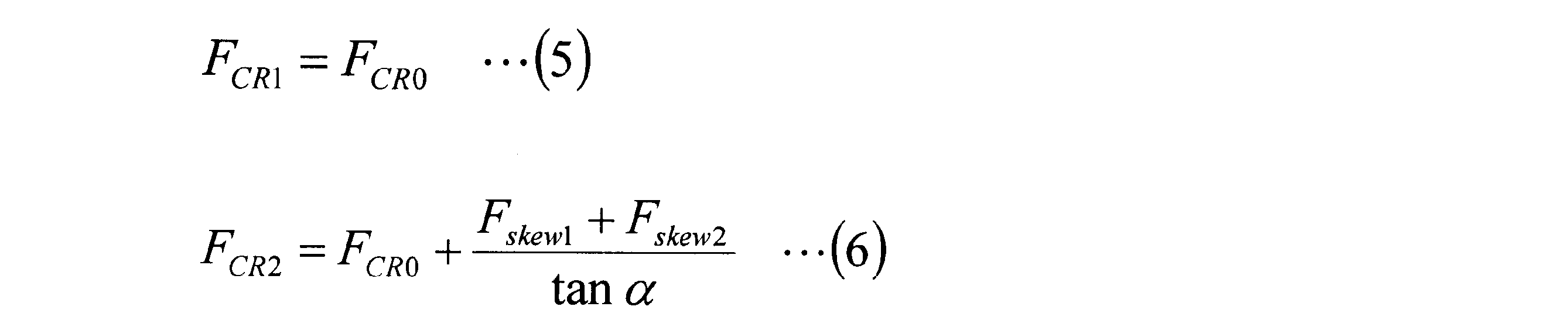
ここで、摩擦ローラ式減速機100の中間ローラ19の数をnとすると、(6)式より、法線力FCR2は(7)式のように表せる。

以上のことから、中間ローラ19に角度φのスキューが生じた場合、任意の時間tにおける法線力FCR(t)は、(1)式及び(7)式から、(8)式のように表すことができる。

(8)式から、前述のサンローラ15と中間ローラ19との間でスキューが生じた場合と同様に、n・μ/tanα≧1の条件下でローラにスキューが生じると、法線力FCRが発散することが分かる。
図12,図13においては、リングローラ17側をテーパ面、サンローラ15側を接触角を有さないトラクション面として説明したが、サンローラ15側をテーパ面とし、リングローラ17側を接触角を有さないトラクション面としても、前述の条件は同じである。
ここで、具体的な数値を一例として挙げて前述の条件を説明する。ここでは、中間ローラ19を3つ有した摩擦ローラ式減速機100において、最大トラクション係数μmax=0.1のトラクションオイルを用いるものとする。
ローディングカム機構を有したローラ(図1においてはリングローラ17)には、軸方向荷重を法線力に変換するためのテーパが設けられており、このテーパの傾斜角をαとする。
その場合には、前述の収束条件式である、n・μ/tanα<1から、tanα>0.3が求まり、傾斜角αを16.7°よりも大きく設計すべきことが分かる。
一般的にトラクションオイルのトラクション特性のカーブ(図12参照)は、接触面圧やトラクション面の周速、伝達動力、油温等によって変化することが知られている。そのため、最大トラクション係数μmaxは、これら各条件の組合せにおける最大値であることが好ましい。
次に、サンローラ15及びリングローラ17の双方のトラクション面にテーパ面を有する場合を例示する。
図15は、サンローラ15及びリングローラ17の双方のトラクション面をテーパ面とした場合に、中間ローラ19とサンローラ15にスキューが生じた様子を示す説明図である。
図15は、サンローラ15及びリングローラ17の双方のトラクション面をテーパ面とした場合に、中間ローラ19とサンローラ15にスキューが生じた様子を示す説明図である。
リングローラ17と中間ローラ19との間の初期法線力をFCS0、一対のリングローラ素子27,29と中間ローラ19との間の各スキュー力をFskew1,Fskew2、トラクション面の傾斜角をαとすると、一対のリングローラ素子27,29と中間ローラ19との間の各法線力FCS1,FCS2は、(9)、(10)式で表せる。

ここで、摩擦ローラ式減速機100の中間ローラ19の数をnとすると、(10)式より、法線力FCS2は、(11)式で表せる。

以上のことから、中間ローラ19に角度φのスキューが生じた場合、任意の時間tにおける法線力FCS(t)は、(1)式及び(11)式から、以下の(12)式のように表すことができる。

(12)式から、n・μ/(2tanα)≧1の条件下で、ローラにスキューが生じると、法線力FCSが発散することが分かる。これに対し、n・μ/2(tanα)<1とすれば、ローラにスキューが生じても、法線力FCSが所定値内で収束するため、トラクション部品が破損するまでに至らない。
<各ローラの支持形態について>
上記構成の摩擦ローラ式減速機100においては、ローディングカム機構の動作、各ローラのミスアライメント、或いはスキューによって、例えば、サンローラと中間ローラとの軸方向位置がずれることがある。その場合、サンローラの凹状のトラクション面の円弧中心と、中間ローラの凸状のトラクション面の円弧中心とが一致せず、サンローラと中間ローラとの接触面に接触角が生じる。
上記構成の摩擦ローラ式減速機100においては、ローディングカム機構の動作、各ローラのミスアライメント、或いはスキューによって、例えば、サンローラと中間ローラとの軸方向位置がずれることがある。その場合、サンローラの凹状のトラクション面の円弧中心と、中間ローラの凸状のトラクション面の円弧中心とが一致せず、サンローラと中間ローラとの接触面に接触角が生じる。
ローラ間の接触面に接触角が生じると、接触面内の滑りが増えてトルク伝達効率が低下する。また、接触面に法線力の軸方向分力が発生するため、各トラクション面の法線力にアンバランスが生じる。法線力がアンバランスになると、接触面における接線力もアンバランスとなり、中間ローラをスキューさせる力が作用する可能性がある。
そこで、図1に示す入力軸11からの駆動力を中間ローラ19に伝達するサンローラ15と、中間ローラ19からの駆動力を出力軸13に伝達するリングローラ17のうち、いずれか一つのローラを、軸回転可能で且つ軸方向変位不能に支持し、上記いずれか一つのローラ以外のローラは、軸回転可能で且つ軸方向変位可能に支持する構成にする。
上記の摩擦ローラ式減速機と出力軸の具体的な構成例を図16に示す。図16は、摩擦ローラ式減速機の出力軸支持構造を示す正面図である。
摩擦ローラ式減速機100に接続される出力軸13Aは、図示しないハウジングに円筒ころ軸受81を介して回転自在に支持される。円筒ころ軸受81は、出力軸13Aを軸方向変位可能に支持する。また、出力軸13Aの摩擦ローラ式減速機100との接続側とは反対側の一端部には、図示しない被駆動体に回転トルクを伝達するトルク伝達部83が設けてある。このトルク伝達部83としては、出力軸13Aの軸方向変位を吸収可能なボールスプラインを用いることができる。
中間ローラ19は、前述したように、ニードル軸受22(図1参照)によって軸回転可能で且つ軸方向変位可能に支持される。
上記した摩擦ローラ式減速機100と、出力軸13Aの支持構造においては、図1に示すように、入力軸11Aに接続されるサンローラ15は、軸回転可能で且つ軸方向変位不能に支持される。また、中間ローラ19と、リングローラ17の可動リングローラ素子29は、それぞれ軸回転可能で且つ軸方向変位可能に支持される。
上記構成によれば、摩擦ローラ式減速機100のローディングカム機構23によって可動リングローラ素子29が軸方向に変位すると、この軸方向移動に伴って、中間ローラ19とサンローラ15に軸方向力が作用する。この軸方向力により、中間ローラ19は軸方向に変位する。一方、サンローラ15は、軸方向に変位不能に支持されるため、出力軸13Aをサンローラ15への軸方向力の作用方向とは逆向きに変位させる。
この出力軸13Aの変位の際、出力軸13Aに設けたトルク伝達部83のボールスプラインによって、被駆動体との間の軸方向変位が吸収される。このため、中間ローラ19や出力軸13Aが軸方向に変位しても、被駆動体に軸方向変位の影響が及ぶことなく、しかも、サンローラ15と中間ローラ19との接触点のずれの発生が抑えられる。
よって、本構成によれば、ローラのミスアライメントやスキューの発生によって、ローラが競り合うことを防止でき、摩擦ローラ式減速機100の耐久性、トルク伝達効率の向上が図られる。
図17は、摩擦ローラ式減速機の出力軸支持構造の他の例を示す分解斜視図である。
本構成の摩擦ローラ式減速機200は、入力軸11と同心に配置される図示しないサンローラと、リングローラ17と、複数の中間ローラ19と、リングローラ17と出力軸13とを連結する連結部85と、ローディングカム機構23と、を備える。
本構成の摩擦ローラ式減速機200は、入力軸11と同心に配置される図示しないサンローラと、リングローラ17と、複数の中間ローラ19と、リングローラ17と出力軸13とを連結する連結部85と、ローディングカム機構23と、を備える。
リングローラ17Aは、固定リングローラ素子27と、軸方向に移動自在な可動リングローラ素子29とを有する。リングローラ素子27,29は、円筒状のリングローラ収容部87の内側に収容された状態で、サンローラ及び入力軸11と同心に配置される。
また、出力軸13には円板状の基端部89が固定される。これらリングローラ収容部87と基端部89とは、連結部85を構成する。
基端部89の外周には、固定リングローラ素子27やカムリング49と同様に、複数の突起爪91が径方向外側に突出して形成される。これら突起爪91は、リングローラ収容部87の内径面に形成された凹溝43に挿入される。凹溝43内の突起爪91は、円周方向(回転方向)にはがたつきがない状態で係合され、軸方向には摺動変位可能に係合される。これにより、リングローラ収容部87と基端部89は、リングローラ17Aからの回転トルクを出力軸13に伝達する。
つまり、本構成の連結部85は、出力軸13側の基端部89と、リングローラ17A側のリングローラ収容部87とが別体に構成される。リングローラ17Aと出力軸13との間のトルク伝達は、基端部89の突起爪91とリングローラ収容部87の凹溝43とが係合し、基端部89とリングローラ収容部87とが一体に回転することで行われる。
上記構成においては、リングローラ17Aと中間ローラ19とが軸回転可能で且つ軸方向変位可能に支持され、不図示のサンローラが軸回転可能で且つ軸方向変位不能に支持される。これにより、可動リングローラ素子29が軸方向変位して、中間ローラ19やサンローラに軸方向力が作用すると、中間ローラ19は軸方向変位する。一方、サンローラは、軸方向力を受けても軸方向への移動が不能である。そのため、サンローラ周囲の中間ローラ19、リングローラ17A、リングローラ収容部87が、軸方向力の作用方向とは逆向きに変位する。
すなわち、リングローラ収容部87の凹溝43と、基端部89の突起爪91とは、軸方向力によって軸方向へ相対変位する。その結果、発生した軸方向力による変位が吸収され、サンローラと中間ローラ19との接触点のずれが抑えられる。また、本構成では、図16に示す構成とは異なり、出力軸13が軸方向に変位しないため、ボールスプラインのような複雑なトルク伝達部を出力軸13に設ける必要がなくなる。
更に、連結部85が大径となるため、突起爪91と凹溝43に作用する荷重は比較的小さくなる。そのため、突起爪91と凹溝43に、特に高い部材強度を持たせる必要がなくなる。また、凹溝43は、前述の固定リングローラ素子27、カムリング49(図1参照)の突起28,61が係合される溝と共用する構成としている。これにより、摩擦ローラ式減速機を製造する際の加工工数を削減でき、減速機を安価な構成にできる。
図16,図17に示す摩擦ローラ式減速機の構成においては、中間ローラ19と可動リングローラ素子29とが軸方向変位可能に支持されるが、軸方向変位可能なローラの組合せは、これに限らない。
しかしながら、サンローラの回転速度は他のローラより高いため、各ローラ間の回転速度のバランスを良化させることが求められる。その場合には、中間ローラ19と可動リングローラ素子29とを軸方向に変位可能とし、サンローラ15を軸方向変位不能に支持する構成にすることが好ましい。この構成によれば、高速回転するサンローラ15側の入力軸11に、ボールスプラインのような複雑な構造体を設けずに済む。
[第2構成例]
次に、摩擦ローラ式減速機の第2構成例を説明する
<中間ローラのキャリアへの支持形態>
本構成の摩擦ローラ式減速機は、基本的に前述の図1に示す構成と同様である。ここで、中間ローラ19の支持形態について説明する。図18は第2構成例の摩擦ローラ式減速機300の要部拡大断面図、図19は中間ローラ19を支持する揺動ホルダ32の一部断面斜視図である。
次に、摩擦ローラ式減速機の第2構成例を説明する
<中間ローラのキャリアへの支持形態>
本構成の摩擦ローラ式減速機は、基本的に前述の図1に示す構成と同様である。ここで、中間ローラ19の支持形態について説明する。図18は第2構成例の摩擦ローラ式減速機300の要部拡大断面図、図19は中間ローラ19を支持する揺動ホルダ32の一部断面斜視図である。
図18,図19に示すように、中間ローラ19は、トラクション面となる外周面19aを有するローラ本体19Aと、ローラ本体19Aの両端部の端面19b,19bから軸方向に延設される一対の支持軸31,31と、を有する。中間ローラ19は、ローラ本体19Aと一対の支持軸31,31とが一体に形成された中実体である。
一対の支持軸31,31は、それぞれニードル軸受22を介して揺動ホルダ32のアーム部173,175に支持される。
揺動ホルダ32は、一方のアーム部173を有する本体部177と、他方のアーム部175との2部品が、揺動軸179Bに設けたねじを用いて接合される。
本体部177は、アーム部173と、アーム部173の基端側が接続される基部181とを有する。基部181の内部には、揺動軸179A,179Bが挿通される後述の揺動軸孔が形成される。
アーム部173,175は、それぞれの先端側に、中間ローラ19の支持軸31を収容する軸穴182が対面して形成される。軸穴182は、一端が閉口した止まり穴となっており、この軸穴182に、中間ローラ19の支持軸31がニードル軸受22を介して支持される。
ニードル軸受22は、針状ころ183と保持器185と外輪187とを有するシェル型ニードル軸受、又はソリッド型ニードル軸受である。ニードル軸受22は、中間ローラ19を、回転自在に、且つ軸方向へ移動自在に支持する。
上記構成の揺動ホルダ32は、図1に示すように、支持軸31,31が入力軸11と平行にして配置される。また、揺動ホルダ32は、中間ローラ19を入力軸11の径方向へ移動(揺動)可能にキャリア33に支持される。
図20はキャリア33の分解斜視図である。キャリア33は、キャリア本体191と、キャリア本体191の一端側に固定される円輪状の連結板193とを有する。キャリア本体191は、円輪状の底部195、及び底部195の円周方向に等間隔となる複数箇所(図示例では3箇所)に立設された柱部197を有する。連結板193は、柱部197の先端部197aに固定される。
柱部197と連結板193は、軸方向に沿って貫通するボルト挿通孔199,201が形成される。キャリア本体191は、ボルト挿通孔199,201に挿入されるボルト等の締結部材によって、図示しないモータ本体に固定される。
円周方向に並ぶ柱部197同士の間には、中間ローラ19を支持する揺動ホルダ32が配置される。揺動ホルダ32の一方の揺動軸179Bは、連結板193に形成された軸孔205に挿入される。また、他方の揺動軸(図19の揺動軸179A)は、キャリア本体191の底部195に形成された軸孔(図示略)に挿入される。これにより、中間ローラ19は、揺動軸179,179Bを中心に揺動可能に軸支され、中間ローラ19がキャリア33の径方向へ出没自在となる。
上記のように、揺動ホルダ32は、複数の中間ローラ19に対して、それぞれ独立して設けられ、各揺動ホルダ32に一つの中間ローラ19が支持される。
<中間ローラの軸方向変位>
次に、中間ローラ19の軸方向変位について説明する。
本構成の摩擦ローラ式減速機300は、図1、図18に示すように、ローディングカム機構23が、リングローラ素子27,29のうち一方の軸方向外側である外側端面側にのみ配置される。ローディングカム機構23は、入力軸11からの回転トルクに応じて、可動リングローラ素子29を固定リングローラ素子27に向けて変位させる。すると、中間ローラ19には軸方向力が作用する。
次に、中間ローラ19の軸方向変位について説明する。
本構成の摩擦ローラ式減速機300は、図1、図18に示すように、ローディングカム機構23が、リングローラ素子27,29のうち一方の軸方向外側である外側端面側にのみ配置される。ローディングカム機構23は、入力軸11からの回転トルクに応じて、可動リングローラ素子29を固定リングローラ素子27に向けて変位させる。すると、中間ローラ19には軸方向力が作用する。
中間ローラ19は、この軸方向力を受けて軸方向にスライドする。このスライド動作は、ニードル軸受22によって実現される。ニードル軸受22は、中間ローラ19の軸方向変位を阻害せず、低抵抗でスムーズなスライド動作を可能にする。これによって、中間ローラ19がローディングカム機構23から軸方向力を受けた場合に、円滑にスライドし、摩耗やフリクションの発生を抑制する。これにより、各トラクション面の面圧が不均衡になることを防止できる。
なお、中間ローラ19は、軸方向移動が可能なように揺動ホルダ32に支持される。ローラ本体19Aの一方及び他方の端面19bと、揺動ホルダ32のホルダ内面との間、すなわち、端面19bと一対のアーム部173,175の対面する内面との間には、それぞれ隙間δが形成される。これらの隙間δによって中間ローラ19の軸方向移動が可能となる。
<揺動ホルダの構造>
次に、揺動ホルダ32の基部181の更に詳細な構成を説明する。図21に中間ローラ19を支持する揺動ホルダ32の一部断面斜視図を示す。
次に、揺動ホルダ32の基部181の更に詳細な構成を説明する。図21に中間ローラ19を支持する揺動ホルダ32の一部断面斜視図を示す。
揺動ホルダ32は、本体部177とアーム部175とが、揺動軸179Bによって接合される。揺動ホルダ171の基部181には揺動軸179A,179Bが取り付けられる揺動軸孔211が形成される。
基部181は、揺動軸孔211内に雌ねじ部213と、大径部215とを有する。アーム部175には、大径部215と同径の揺動軸孔217が形成される。
これら揺動軸孔211,217に挿入される揺動軸179Bは、基部181への挿入先端側から順に、結合用の雄ねじ部219と、位置決め部221と、フランジ部223と、キャリア189の揺動軸孔211に挿入される係止軸225とを有する。
この揺動軸179Bは、アーム部175の揺動軸孔217を通じて、基部181の揺動軸孔211に挿入され、先端の雄ねじ部219が雌ねじ部213と螺合する。揺動軸179Bは、フランジ部223の一端面がアーム部175に当接し、ねじの螺合により双方を締め付けた状態で固定される。
このとき、位置決め部221が、大径部215と揺動軸孔217に嵌入されることで、基部181とアーム部175とが位置決めされる。つまり、揺動軸179Bの位置決め部221と、大径部215及び揺動軸孔217とは、インロー接続機能を有する。揺動軸179の位置決め部221の一部には、後述する油路となる環状溝227が形成される。
揺動軸179Aは、基部181への挿入先端側から順に、位置決め部231と、フランジ部233と、キャリア189の軸孔に挿入される係止軸235とを有する。位置決め部231の一部には、後述する油路となる環状溝237が形成される。
<中間ローラの支持構造による作用効果>
以上説明した中間ローラ19の支持構造によれば、次の作用効果が得られる。
図19に示すように、中間ローラ19を支持するニードル軸受22をトラクション面の両脇側に配置することで、ニードル軸受22が中間ローラ19の弾性変形の影響を受けなくなる。よって、中間ローラ19に法線力が負荷されても、ニードル軸受22の軸受内部すきまが縮小しない。これにより、ニードル軸受22の耐久寿命を向上できる。
以上説明した中間ローラ19の支持構造によれば、次の作用効果が得られる。
図19に示すように、中間ローラ19を支持するニードル軸受22をトラクション面の両脇側に配置することで、ニードル軸受22が中間ローラ19の弾性変形の影響を受けなくなる。よって、中間ローラ19に法線力が負荷されても、ニードル軸受22の軸受内部すきまが縮小しない。これにより、ニードル軸受22の耐久寿命を向上できる。
また、ニードル軸受22のスキューによる軸方向荷重の発生が低減される。更に、中間ローラ19の両脇側が支持されるため、ローラ本体19Aの内周で支持する場合と比較して、支持スパンが広くなる。その結果、ニードル軸受22と中間ローラ19との相対スキューが生じ難くなる。
また、中間ローラ19は、ローラ本体19Aと支持軸31,31とが一体になった中実構造であるため、剛性が高められる。これにより、中空構造よりも法線力による弾性変形量が少なくなり、可動リングローラ素子29からの軸方向推力による中間ローラ19の軸方向変位を小さく抑えることができる。
更に、中間ローラ19のバランス修正が容易となり、重心ずれによる異常振動を防止でき、安定した高速回転を実現できる。また、中間ローラ19は、剛性の向上により共振周波数が高められ、これによっても、共振による異常振動の発生が低減される。中間ローラ19が中実構造であることの上記作用効果は、サンローラ15に対しても同様のことがいえる。
図22に揺動ホルダ32が支持されたキャリア33の一部断面斜視図を示す。揺動軸179Aのフランジ部233は、一方の端面233aが揺動軸179Aの締結時の座面として機能する。他方の端面233bは、キャリア33の連結板193との当接面となる。連結板193の軸孔205には、滑りブッシュ241が装填され、滑りブッシュ241内に揺動軸179Aの係止軸235が挿入される。係止軸235は、フランジ部233と連結板193との間にワッシャ243が介装される。
揺動軸179Bのフランジ部223も同様に、一方の端面223aは揺動軸179Bの締結時の座面として機能する。他方の端面223bは、キャリア33のキャリア本体191との当接面となる。そして、揺動軸179A,179Bの各係止軸225,235には、それぞれ滑りブッシュ241とワッシャ243が介装される。
このような構成にすると、フランジ部233,223がキャリア33に挟持された状態になる。そのため、仮に揺動軸179A,179Bのねじ等が緩むことがあっても、揺動軸179A,179Bが軸孔205,206から抜け落ちることはなく、揺動ホルダ32が分解することもない。
<中間ローラの支持軸受への給油路>
次に、中間ローラ19の支持軸受に潤滑油を供給する給油路について説明する。
中間ローラ19は、高速回転駆動されるため給油が不可欠な部材である。しかし、中間ローラ19に上記の軸方向力が作用すると、中間ローラ19の軸方向変位によって、給油位置が狙った位置からずれることがある。そこで、中間ローラ19への給油油路を別途に設け、中間ローラ19に確実な給油を行うことが望ましいが、軸方向移動に対応させる油路構造が複雑となり、装置自体の製造コストやメンテナンスコストを増大させる要因となる。
次に、中間ローラ19の支持軸受に潤滑油を供給する給油路について説明する。
中間ローラ19は、高速回転駆動されるため給油が不可欠な部材である。しかし、中間ローラ19に上記の軸方向力が作用すると、中間ローラ19の軸方向変位によって、給油位置が狙った位置からずれることがある。そこで、中間ローラ19への給油油路を別途に設け、中間ローラ19に確実な給油を行うことが望ましいが、軸方向移動に対応させる油路構造が複雑となり、装置自体の製造コストやメンテナンスコストを増大させる要因となる。
本構成の摩擦ローラ式減速機300は、中間ローラ19がニードル軸受22によって軸方向移動自在に支持される。この構成であっても、潤滑油の供給油路を複雑化することなく、潤滑油を適正な供給位置に適正な油量で供給可能になっている。
図23は揺動ホルダ32を揺動軸179A,179Bの中心軸を含む面で切断した一部断面斜視図である。キャリア33に形成された潤滑油供給路247(図22参照)は、揺動軸179Bに潤滑油を供給する。図23に示すように、揺動軸179A,179Bは、油路となる軸孔251,253が内径部に形成される。
潤滑油は、これら軸孔251,253を通じて、アーム部173,175に形成された油路255,257へ供給される。
具体的には、揺動軸179Bの軸孔251に供給された潤滑油の一部は、位置決め部221の一部に形成された環状溝227内に、図示しない開口孔を通じて供給される。同様に、揺動軸179Aの位置決め部231に形成された環状溝237内にも潤滑油が供給される。
環状溝227内の潤滑油は、アーム部175に形成された油路255を通じてニードル軸受22を支持する軸穴182に送られる(図中矢印D1)。また、環状溝237内の潤滑油も同様に、アーム部173に形成された油路257を通じてアーム部173側の軸穴182に送られる。
図24はアーム部175単体の斜視図、図25は図24に示すIIXV-IIXV線断面斜視図である。アーム部175は、揺動軸179B(図23参照)が挿入される揺動軸孔217と、ニードル軸受22(図23参照)を支持する軸穴182と、揺動軸孔217から軸穴182までを連通する油路255とが形成される。
油路255は、孔部259を通じて穿設される直線状の孔である。また、軸穴182の内周面には、軸穴182の軸線に沿って油溝261が形成される。油溝261は、軸穴182の底部側から油路255の開口部まで形成され、油路255と連通する。軸穴182の底部に油溝261が穿設された部位には、潤滑油が漏れないように止め栓263(図23参照)が圧入される。
図23に示す油路255を通じて供給された潤滑油は、軸穴182内の油溝261と外輪187の外周面との間に形成される油路を通じて、軸穴182の底部に供給される(図中矢印D2)。軸穴182の底部に到達した潤滑油は、外輪187の端面を通じてニードル軸受22の径方向内側に向かい(図中矢印D3)、支持軸31上のニードル軸受22の内部空間を通過する(図中矢印D4)。
また、アーム部173側についても同様に、潤滑油がD1~D4で示す流れに対応する流れに沿って供給される。
上記の油路255,257、孔部259、油溝261等の各油路は、放電加工や機械加工によって形成する。例えば、油路255及び孔部259、並びに油路257及び孔部259は、アーム部173,175の先端側から揺動中心の基端側に向けて形成される。油溝261は軸穴182の底部外側から油路255の開口に向けて形成される(アーム部173側も同様)。油路255,257を形成する際に開口したアーム部173,175の先端の孔部259,259は、ニードル軸受22の外輪187によって塞がれるため、止め栓を組み込む必要はない。
本構成の摩擦ローラ式減速機300によれば、中間ローラ19に供給する潤滑油の供給油路を複雑化せず、中間ローラ19が軸方向に移動した場合でも、適正な供給位置に適正な油量の潤滑油を供給できる。また、ニードル軸受22に常に適正量の潤滑油が供給され、中間ローラ19の円滑な回転が実現できる。
以上、説明したように、本発明は上記の実施形態に限定されるものではなく、実施形態の各構成を相互に組み合わせることや、明細書の記載、並びに周知の技術に基づいて、当業者が変更、応用することも本発明の予定するところであり、保護を求める範囲に含まれる。
本出願は2015年3月30日出願の日本国特許出願(特願2015-69846)、2015年6月9日出願の日本国特許出願(特願2015-116760)、及び2015年4月13日出願の日本国特許出願(特願2015-81887)に基づくものであり、その内容はここに参照として取り込まれる。
11 入力軸
13 出力軸
15 サンローラ
15a 外周面
17 リングローラ
17a 内周面
19 中間ローラ
19a 外周面(トラクション面)
19b,19b 端面
19A ローラ本体
21 連結部
22 ニードル軸受
23 ローディングカム機構
27 固定リングローラ素子(固定ローラ素子)
27a 内周面(転がり接触面)
29 可動リングローラ素子(可動ローラ素子)
29a 内周面(転がり接触面)
31 支持軸(自転軸)
32 揺動ホルダ(ホルダ)
49 カムリング
51 玉(転動体)
53 第1カム溝
55 第2カム溝
133,135 対向側端面
137,139 外側端面
179A,179B 揺動軸
100,200,300 摩擦ローラ式減速機
Claims (4)
- 入力軸と同心に配置されるサンローラと、前記サンローラの外周側に前記サンローラと同心に配置されるリングローラと、前記サンローラの外周面と前記リングローラの内周面との間で、前記入力軸と平行な自転軸を中心として回転自在に支持され、前記サンローラの外周面と前記リングローラの内周面に転がり接触する複数の中間ローラと、前記リングローラと出力軸とを連結する連結部と、各ローラの転がり接触面の接触面圧を変更するローディングカム機構と、を備える摩擦ローラ式減速機であって、
前記リングローラは、前記入力軸の軸方向に並設された一対のローラ素子からなり、
前記一対のローラ素子の少なくとも一方は、前記軸方向に移動自在な可動ローラ素子であり、
前記ローディングカム機構は、前記可動ローラ素子の前記軸方向の外側端面側にのみ配置され、前記入力軸の回転トルクに応じて、前記可動ローラ素子を他方の前記ローラ素子に向けて変位させるものであり、
前記サンローラの外周面は、軸断面の外縁形状が単一円弧状の凹曲線となる凹曲面であり、
前記中間ローラの外周面は、軸断面の外縁形状が単一円弧状の凸曲線となる凸曲面である
摩擦ローラ式減速機。 - 前記ローディングカム機構は、該可動ローラ素子の外側端面の円周方向に沿った複数箇所に設けられた第1カム溝と、前記可動ローラ素子の外側端面に対面配置され前記第1カム溝に対応する複数箇所に第2カム溝が設けられたカムリングと、前記第1カム溝と前記第2カム溝との間にそれぞれ挟持される複数の転動体と、を有し、前記第1カム溝と前記第2カム溝は、それぞれ前記軸方向の深さが円周方向に沿って漸次変化して、カム溝の円周方向端部に向かうに従って浅くなる形状にされている
請求項1に記載の摩擦ローラ式減速機。 - 前記中間ローラと、前記サンローラと、前記リングローラのうち、
いずれか一つのローラは、軸回転可能で且つ軸方向変位不能に支持され、
前記いずれか一つのローラ以外のローラは、軸回転可能で且つ軸方向変位可能に支持される
請求項1又は請求項2に記載の摩擦ローラ式減速機。 - 複数の前記中間ローラのそれぞれに設けられ、前記自転軸を支持するホルダを備え、
前記中間ローラは、前記サンローラの外周面と前記リングローラの内周面に転がり接触するトラクション面を外周面に有するローラ本体の両端部に、前記自転軸が延設され、
前記ホルダは、ホルダ内面と前記ローラ本体の端面との間に、前記中間ローラが前記軸方向に移動可能な隙間を有し、前記自転軸をニードル軸受を介して回転自在、且つ前記軸方向へ移動自在に支持する
請求項3に記載の摩擦ローラ式減速機。
Priority Applications (4)
| Application Number | Priority Date | Filing Date | Title |
|---|---|---|---|
| EP16771990.5A EP3279509B1 (en) | 2015-03-30 | 2016-02-24 | Friction roller type reduction gear |
| US15/562,315 US10359102B2 (en) | 2015-03-30 | 2016-02-24 | Friction roller-type reduction gear |
| EP21174753.0A EP3889465B1 (en) | 2015-03-30 | 2016-02-24 | Friction roller-type reduction gear |
| JP2017509388A JP6702310B2 (ja) | 2015-03-30 | 2016-02-24 | 摩擦ローラ式減速機 |
Applications Claiming Priority (6)
| Application Number | Priority Date | Filing Date | Title |
|---|---|---|---|
| JP2015-069846 | 2015-03-30 | ||
| JP2015069846 | 2015-03-30 | ||
| JP2015-081887 | 2015-04-13 | ||
| JP2015081887 | 2015-04-13 | ||
| JP2015-116760 | 2015-06-09 | ||
| JP2015116760 | 2015-06-09 |
Publications (1)
| Publication Number | Publication Date |
|---|---|
| WO2016158106A1 true WO2016158106A1 (ja) | 2016-10-06 |
Family
ID=57004426
Family Applications (1)
| Application Number | Title | Priority Date | Filing Date |
|---|---|---|---|
| PCT/JP2016/055533 Ceased WO2016158106A1 (ja) | 2015-03-30 | 2016-02-24 | 摩擦ローラ式減速機 |
Country Status (4)
| Country | Link |
|---|---|
| US (1) | US10359102B2 (ja) |
| EP (2) | EP3889465B1 (ja) |
| JP (1) | JP6702310B2 (ja) |
| WO (1) | WO2016158106A1 (ja) |
Families Citing this family (4)
| Publication number | Priority date | Publication date | Assignee | Title |
|---|---|---|---|---|
| DE102017106525A1 (de) * | 2016-03-28 | 2017-09-28 | Kabushiki Kaisha Toyota Jidoshokki | Drehzahlerhöher und Zentrifugalkompressor |
| JP6583101B2 (ja) * | 2016-03-31 | 2019-10-02 | 株式会社豊田自動織機 | 増速機 |
| US10415676B1 (en) * | 2016-10-06 | 2019-09-17 | X Development Llc | Roller traction drive |
| JP6977682B2 (ja) | 2018-07-25 | 2021-12-08 | 株式会社デンソー | 回転電機ユニット |
Citations (5)
| Publication number | Priority date | Publication date | Assignee | Title |
|---|---|---|---|---|
| JPS5292068A (en) * | 1976-01-30 | 1977-08-03 | Nissan Motor Co Ltd | Traction transmission apparatus |
| JPH01229155A (ja) * | 1988-03-07 | 1989-09-12 | Yashima Eng Kk | 減速装置 |
| WO2013174740A1 (de) * | 2012-05-24 | 2013-11-28 | Volkswagen Aktiengesellschaft | Reibrollenplanetengetriebe sowie übersetzungs- und ausgleichsgetriebe |
| JP2014040892A (ja) * | 2012-08-23 | 2014-03-06 | Nsk Ltd | 摩擦ローラ式変速機 |
| JP2014196825A (ja) * | 2013-03-07 | 2014-10-16 | 日本精工株式会社 | 摩擦ローラ式減速機 |
Family Cites Families (15)
| Publication number | Priority date | Publication date | Assignee | Title |
|---|---|---|---|---|
| US3283614A (en) * | 1963-04-10 | 1966-11-08 | Gen Motors Corp | Friction drive mechanism |
| US3641842A (en) * | 1969-11-25 | 1972-02-15 | Gen Motors Corp | Roller traction drive |
| US3682020A (en) * | 1970-10-20 | 1972-08-08 | Gen Motors Corp | Traction-drive transmission |
| JPS57184351U (ja) * | 1981-05-18 | 1982-11-22 | ||
| JP2606851Y2 (ja) * | 1993-09-16 | 2001-01-29 | 三菱重工業株式会社 | 摩擦伝動装置 |
| US7118512B2 (en) * | 2000-09-08 | 2006-10-10 | Iowa State University Research Foundation, Inc. | Self-actuating, traction-drive speed changer |
| JP2004116670A (ja) | 2002-09-26 | 2004-04-15 | Ntn Corp | 遊星ローラ式変速機 |
| JP4901556B2 (ja) * | 2007-04-03 | 2012-03-21 | 株式会社豊田中央研究所 | トラクションドライブ機構 |
| EP2687752B1 (en) * | 2011-03-16 | 2019-08-21 | NSK Ltd. | Friction roller type deceleration device and drive device for electric automobile |
| JP5899850B2 (ja) | 2011-11-17 | 2016-04-06 | 日本精工株式会社 | 摩擦ローラ式減速機 |
| JP2013108572A (ja) * | 2011-11-22 | 2013-06-06 | Nsk Ltd | 摩擦ローラ式減速機 |
| JP2014040885A (ja) | 2012-08-23 | 2014-03-06 | Nsk Ltd | 摩擦ローラ式変速機 |
| JP2015069846A (ja) | 2013-09-30 | 2015-04-13 | 東芝ライテック株式会社 | 発光モジュール、管形発光ランプおよび照明器具 |
| JP6332938B2 (ja) | 2013-10-24 | 2018-05-30 | 住友重機械搬送システム株式会社 | 充放電検査装置 |
| JP2015116760A (ja) | 2013-12-19 | 2015-06-25 | セイコーエプソン株式会社 | 印刷装置 |
-
2016
- 2016-02-24 JP JP2017509388A patent/JP6702310B2/ja active Active
- 2016-02-24 EP EP21174753.0A patent/EP3889465B1/en active Active
- 2016-02-24 EP EP16771990.5A patent/EP3279509B1/en active Active
- 2016-02-24 US US15/562,315 patent/US10359102B2/en active Active
- 2016-02-24 WO PCT/JP2016/055533 patent/WO2016158106A1/ja not_active Ceased
Patent Citations (5)
| Publication number | Priority date | Publication date | Assignee | Title |
|---|---|---|---|---|
| JPS5292068A (en) * | 1976-01-30 | 1977-08-03 | Nissan Motor Co Ltd | Traction transmission apparatus |
| JPH01229155A (ja) * | 1988-03-07 | 1989-09-12 | Yashima Eng Kk | 減速装置 |
| WO2013174740A1 (de) * | 2012-05-24 | 2013-11-28 | Volkswagen Aktiengesellschaft | Reibrollenplanetengetriebe sowie übersetzungs- und ausgleichsgetriebe |
| JP2014040892A (ja) * | 2012-08-23 | 2014-03-06 | Nsk Ltd | 摩擦ローラ式変速機 |
| JP2014196825A (ja) * | 2013-03-07 | 2014-10-16 | 日本精工株式会社 | 摩擦ローラ式減速機 |
Non-Patent Citations (1)
| Title |
|---|
| See also references of EP3279509A4 * |
Also Published As
| Publication number | Publication date |
|---|---|
| EP3279509A4 (en) | 2018-05-02 |
| JPWO2016158106A1 (ja) | 2018-01-25 |
| EP3889465B1 (en) | 2022-10-12 |
| US20180347675A1 (en) | 2018-12-06 |
| JP6702310B2 (ja) | 2020-06-03 |
| US10359102B2 (en) | 2019-07-23 |
| EP3889465A1 (en) | 2021-10-06 |
| EP3279509A1 (en) | 2018-02-07 |
| EP3279509B1 (en) | 2021-06-30 |
Similar Documents
| Publication | Publication Date | Title |
|---|---|---|
| JP5720781B2 (ja) | 無段変速機 | |
| US9482323B2 (en) | Friction roller reducer and drive unit for electric automobile | |
| CN103608607A (zh) | 无级变速器 | |
| JP6702310B2 (ja) | 摩擦ローラ式減速機 | |
| JP6117991B2 (ja) | トロイダル無段変速機 | |
| US10161489B2 (en) | Friction-roller-type reduction gear | |
| US20060243259A1 (en) | Supercharger | |
| JP6701901B2 (ja) | 摩擦ローラ式減速機 | |
| US10309501B2 (en) | Friction roller-type transmission | |
| US9670996B2 (en) | Toroidal continuously-variable transmission | |
| WO2019111903A1 (ja) | トリポード型等速自在継手 | |
| JP6485180B2 (ja) | 摩擦ローラ式減速機 | |
| JP6265061B2 (ja) | 遊星ローラ式トラクションドライブ装置 | |
| JP4968082B2 (ja) | トロイダル型無段変速機 | |
| US12234891B2 (en) | Toroidal continuously variable transmission | |
| JP4560894B2 (ja) | 摩擦ローラ式変速機 | |
| JP6314534B2 (ja) | 摩擦ローラ式減速機 | |
| CN103732948B (zh) | 动力滚子单元、其制造方法和半环形无级变速器 | |
| JP7449769B2 (ja) | トロイダル無段変速機 | |
| US20160053831A1 (en) | One-way clutch device | |
| JP6561554B2 (ja) | トロイダル型無段変速機 | |
| JP6492906B2 (ja) | トロイダル型無段変速機 | |
| WO2026058632A1 (ja) | トリポード型等速自在継手 | |
| JP2018146029A (ja) | プーリユニット | |
| JP2016003746A (ja) | トロイダル型無段変速機 |
Legal Events
| Date | Code | Title | Description |
|---|---|---|---|
| 121 | Ep: the epo has been informed by wipo that ep was designated in this application |
Ref document number: 16771990 Country of ref document: EP Kind code of ref document: A1 |
|
| ENP | Entry into the national phase |
Ref document number: 2017509388 Country of ref document: JP Kind code of ref document: A |
|
| REEP | Request for entry into the european phase |
Ref document number: 2016771990 Country of ref document: EP |
|
| NENP | Non-entry into the national phase |
Ref country code: DE |