WO2016158108A1 - 内視鏡診断装置および病変部の体積測定方法 - Google Patents
内視鏡診断装置および病変部の体積測定方法 Download PDFInfo
- Publication number
- WO2016158108A1 WO2016158108A1 PCT/JP2016/055559 JP2016055559W WO2016158108A1 WO 2016158108 A1 WO2016158108 A1 WO 2016158108A1 JP 2016055559 W JP2016055559 W JP 2016055559W WO 2016158108 A1 WO2016158108 A1 WO 2016158108A1
- Authority
- WO
- WIPO (PCT)
- Prior art keywords
- endoscope
- volume
- hood
- distal end
- scope hood
- Prior art date
- Legal status (The legal status is an assumption and is not a legal conclusion. Google has not performed a legal analysis and makes no representation as to the accuracy of the status listed.)
- Ceased
Links
Images


Classifications
-
- A—HUMAN NECESSITIES
- A61—MEDICAL OR VETERINARY SCIENCE; HYGIENE
- A61B—DIAGNOSIS; SURGERY; IDENTIFICATION
- A61B1/00—Instruments for performing medical examinations of the interior of cavities or tubes of the body by visual or photographical inspection, e.g. endoscopes; Illuminating arrangements therefor
- A61B1/00002—Operational features of endoscopes
- A61B1/00004—Operational features of endoscopes characterised by electronic signal processing
- A61B1/00009—Operational features of endoscopes characterised by electronic signal processing of image signals during a use of endoscope
- A61B1/000094—Operational features of endoscopes characterised by electronic signal processing of image signals during a use of endoscope extracting biological structures
-
- A—HUMAN NECESSITIES
- A61—MEDICAL OR VETERINARY SCIENCE; HYGIENE
- A61B—DIAGNOSIS; SURGERY; IDENTIFICATION
- A61B1/00—Instruments for performing medical examinations of the interior of cavities or tubes of the body by visual or photographical inspection, e.g. endoscopes; Illuminating arrangements therefor
- A61B1/00064—Constructional details of the endoscope body
- A61B1/00071—Insertion part of the endoscope body
- A61B1/0008—Insertion part of the endoscope body characterised by distal tip features
- A61B1/00089—Hoods
-
- A—HUMAN NECESSITIES
- A61—MEDICAL OR VETERINARY SCIENCE; HYGIENE
- A61B—DIAGNOSIS; SURGERY; IDENTIFICATION
- A61B1/00—Instruments for performing medical examinations of the interior of cavities or tubes of the body by visual or photographical inspection, e.g. endoscopes; Illuminating arrangements therefor
- A61B1/12—Instruments for performing medical examinations of the interior of cavities or tubes of the body by visual or photographical inspection, e.g. endoscopes; Illuminating arrangements therefor with cooling or rinsing arrangements
-
- A—HUMAN NECESSITIES
- A61—MEDICAL OR VETERINARY SCIENCE; HYGIENE
- A61B—DIAGNOSIS; SURGERY; IDENTIFICATION
- A61B5/00—Measuring for diagnostic purposes; Identification of persons
- A61B5/103—Measuring devices for testing the shape, pattern, colour, size or movement of the body or parts thereof, for diagnostic purposes
- A61B5/107—Measuring physical dimensions, e.g. size of the entire body or parts thereof
- A61B5/1076—Measuring physical dimensions, e.g. size of the entire body or parts thereof for measuring dimensions inside body cavities, e.g. using catheters
-
- A—HUMAN NECESSITIES
- A61—MEDICAL OR VETERINARY SCIENCE; HYGIENE
- A61B—DIAGNOSIS; SURGERY; IDENTIFICATION
- A61B5/00—Measuring for diagnostic purposes; Identification of persons
- A61B5/103—Measuring devices for testing the shape, pattern, colour, size or movement of the body or parts thereof, for diagnostic purposes
- A61B5/107—Measuring physical dimensions, e.g. size of the entire body or parts thereof
- A61B5/1079—Measuring physical dimensions, e.g. size of the entire body or parts thereof using optical or photographic means
-
- G—PHYSICS
- G02—OPTICS
- G02B—OPTICAL ELEMENTS, SYSTEMS OR APPARATUS
- G02B23/00—Telescopes, e.g. binoculars; Periscopes; Instruments for viewing the inside of hollow bodies; Viewfinders; Optical aiming or sighting devices
- G02B23/24—Instruments or systems for viewing the inside of hollow bodies, e.g. fibrescopes
- G02B23/2476—Non-optical details, e.g. housings, mountings, supports
-
- A—HUMAN NECESSITIES
- A61—MEDICAL OR VETERINARY SCIENCE; HYGIENE
- A61B—DIAGNOSIS; SURGERY; IDENTIFICATION
- A61B1/00—Instruments for performing medical examinations of the interior of cavities or tubes of the body by visual or photographical inspection, e.g. endoscopes; Illuminating arrangements therefor
- A61B1/00064—Constructional details of the endoscope body
- A61B1/00071—Insertion part of the endoscope body
- A61B1/0008—Insertion part of the endoscope body characterised by distal tip features
- A61B1/00101—Insertion part of the endoscope body characterised by distal tip features the distal tip features being detachable
-
- A—HUMAN NECESSITIES
- A61—MEDICAL OR VETERINARY SCIENCE; HYGIENE
- A61B—DIAGNOSIS; SURGERY; IDENTIFICATION
- A61B1/00—Instruments for performing medical examinations of the interior of cavities or tubes of the body by visual or photographical inspection, e.g. endoscopes; Illuminating arrangements therefor
- A61B1/06—Instruments for performing medical examinations of the interior of cavities or tubes of the body by visual or photographical inspection, e.g. endoscopes; Illuminating arrangements therefor with illuminating arrangements
- A61B1/0638—Instruments for performing medical examinations of the interior of cavities or tubes of the body by visual or photographical inspection, e.g. endoscopes; Illuminating arrangements therefor with illuminating arrangements providing two or more wavelengths
-
- A—HUMAN NECESSITIES
- A61—MEDICAL OR VETERINARY SCIENCE; HYGIENE
- A61B—DIAGNOSIS; SURGERY; IDENTIFICATION
- A61B1/00—Instruments for performing medical examinations of the interior of cavities or tubes of the body by visual or photographical inspection, e.g. endoscopes; Illuminating arrangements therefor
- A61B1/06—Instruments for performing medical examinations of the interior of cavities or tubes of the body by visual or photographical inspection, e.g. endoscopes; Illuminating arrangements therefor with illuminating arrangements
- A61B1/0653—Instruments for performing medical examinations of the interior of cavities or tubes of the body by visual or photographical inspection, e.g. endoscopes; Illuminating arrangements therefor with illuminating arrangements with wavelength conversion
-
- G—PHYSICS
- G06—COMPUTING OR CALCULATING; COUNTING
- G06T—IMAGE DATA PROCESSING OR GENERATION, IN GENERAL
- G06T2207/00—Indexing scheme for image analysis or image enhancement
- G06T2207/10—Image acquisition modality
- G06T2207/10068—Endoscopic image
-
- G—PHYSICS
- G06—COMPUTING OR CALCULATING; COUNTING
- G06T—IMAGE DATA PROCESSING OR GENERATION, IN GENERAL
- G06T2207/00—Indexing scheme for image analysis or image enhancement
- G06T2207/30—Subject of image; Context of image processing
- G06T2207/30004—Biomedical image processing
- G06T2207/30096—Tumor; Lesion
Definitions
- the present invention relates to a volume measurement of a lesion using an endoscope. More specifically, the present invention relates to an endoscopic diagnostic apparatus and a lesion volume measuring method that make it possible to easily measure the volume of a lesion with an endoscope without using a special measurement instrument.
- An endoscopic diagnostic apparatus is used to observe the inside of the subject.
- the insertion portion of the endoscope is inserted into the body cavity of the subject, and, for example, white light is irradiated as the observation light from the distal end portion to the observation region, and the reflected light is
- the endoscope image is picked up by receiving light.
- the captured endoscopic image is displayed on the display unit, and the endoscopic image is observed by the operator of the endoscopic diagnostic apparatus.
- a method uses a treatment instrument such as a probe with a scale to measure the size of a lesion.
- a scaled probe is inserted from the entrance of the forceps opening of the endoscope and protruded from the exit of the forceps opening at the distal end.
- the tip of the scaled probe is flexible and has a scale for measuring the size. Such a flexible tip is pressed against the region to be observed and bent, and the scale engraved on the tip is read to measure the size of the lesion in the region to be observed.
- Patent Document 1 since a water flow is jetted from two openings at the distal end of an insertion portion of an endoscope to a lesioned part and the distance between the two water streams is equal to the distance between the two openings, the lesioned part It is described that it is determined whether or not is equal to or greater than a treatment reference value.
- Patent Document 2 a treatment tool having an arm part for setting measurement points is used to set a plurality of measurement points around the lesion part, and the lesion part is calculated by calculation based on the coordinate information of the measurement point. Is described.
- the endoscope apparatus of Patent Document 1 a dedicated endoscope having two openings for outputting two water flows from the distal end portion of the insertion portion is necessary. If this endoscope is not used, the size of the lesioned portion is measured. There is a problem that you can not.
- the endoscope apparatus of Patent Document 2 requires a robot arm in order to measure the size of a lesion, and further sets a plurality of measurement points around the lesion by operating the complicated robot arm. There is a problem that must be done.
- An object of the present invention is to eliminate the problems of the prior art, and it is possible to measure the volume of a lesioned part such as a tumor with an endoscope without using a special treatment tool for measurement.
- An object of the present invention is to provide a mirror diagnostic apparatus and a method for measuring a volume of a lesion.
- an endoscope diagnostic apparatus includes an endoscope having a function of pouring water from the distal end of an insertion portion, Water injection amount detecting means for detecting the amount of water injection from the tip of the insertion portion; A scope hood attached to the distal end of the insertion portion of the endoscope; Position detection means for detecting the position of the distal end portion of the scope hood on the image from the image captured by the endoscope; A model detection means for detecting at least one of an endoscope model and a scope hood model; Using the position of the tip of the scope hood detected by the position detector and at least one of the endoscope model and scope hood model detected by the model detector, the tip of the endoscope insertion portion and the scope Space volume detecting means for detecting the volume of the internal space of the scope hood formed by the hood; An endoscopy characterized by having a lesioned part volume detecting means for detecting a volume of a lesioned
- the spatial volume detection means is created according to the scope hood model, and the relationship between the distal end of the scope hood on the image and the volume of the internal space of the scope hood It is preferable to detect the volume of the internal space of the scope hood using Further, in the endoscope diagnosis apparatus according to one aspect of the present invention, the spatial volume detection means calculates a distance from the position of the distal end portion of the scope hood to the distal end surface of the insertion portion of the endoscope to the distal end portion of the scope hood.
- the spatial volume detection means detects the volume of the internal space of the scope hood according to at least one of the endoscope model and the scope hood model.
- flow rate measuring means for measuring a flow rate of water injected by the endoscope, a tank for storing water injected by the endoscope, and a weight of the tank are measured. It has any one or more of a weight measuring means, a time measuring means for measuring the water injection time by the endoscope, and an input means for inputting the water injection amount. Using at least one of the flow rate measurement result, the weight measurement result by the weight measurement unit, the time measurement result by the time measurement unit, and the amount of water injected by the input unit, injection from the distal end of the insertion portion of the endoscope is performed. It is preferable to detect the amount of water.
- a display unit that displays the volume of the lesion part detected by the lesion part volume detection unit, and a record that records the volume of the lesion part detected by the lesion part volume detection unit. It is preferable to have at least one or more of warning means for outputting a warning corresponding to the volume of the lesioned part detected by the means and the lesioned part volume detecting means. Furthermore, in the endoscope diagnosis apparatus according to one aspect of the present invention, a warning is output when the water injection amount detected by the water injection amount measurement unit exceeds the volume of the internal space of the scope hood detected by the space volume detection unit. It is preferable to have water injection amount warning means.
- the lesion volume measuring method uses an endoscope having a scope hood attached to the distal end of the insertion portion, From the image captured by the endoscope, detect the position of the tip of the scope hood on the image, The scope hood internal space formed by the scope hood and the distal end surface of the endoscope insertion part is determined from the position of the distal end of the scope hood on the image and at least one of the endoscope model and the scope hood model. Get the volume Provided is a volume measurement method for a lesion part, in which water is poured until the inside of the scope hood is filled, and the volume of the lesion part is measured from the difference between the amount of water injection and the volume of the internal space of the scope hood.
- the relationship between the distal end portion of the scope hood on the image and the volume of the internal space of the scope hood created according to the scope hood model is used.
- the distance from the distal end surface of the endoscope to the distal end portion of the scope hood is detected from the position of the distal end portion of the scope hood on the image.
- the parameter used to obtain the volume of the internal space of the scope hood is changed according to at least one of the endoscope model and the scope hood model. Is preferred.
- the amount of water injected into the scope hood is a flow rate measuring device for water attached to the endoscope, and a tank storing water injected by the endoscope. It is preferable to detect using any one or more of a change in weight, a time for pouring water into the scope hood, and an amount of water to be poured.
- display of the volume of the measured lesion area, recording of the volume of the measured lesion area, and output of a warning according to the volume of the measured lesion area It is preferred to do any one or more. Further, in the lesion volume measuring method according to one aspect of the present invention, it is preferable to output a warning when the amount of water injected into the scope hood is larger than the volume of the internal space of the scope hood.
- a scope hood generally used as a treatment tool for an endoscope, and a water injection function generally possessed by an endoscope, a lesion such as a tumor is used. Can be easily measured.
- FIG. 1 It is a conceptual diagram which shows an example of the endoscope diagnostic apparatus of this invention. It is a block diagram showing the internal structure of the endoscope diagnostic apparatus shown in FIG. It is a conceptual diagram showing the structure of the front-end
- (A) is a conceptual diagram showing a configuration of a scope hood attached to the distal end portion of the endoscope insertion portion of the endoscope
- (B) is a distal end of the insertion portion of the endoscope shown in FIG. It is a conceptual diagram showing a mode that it mounts
- (A) to (D) are conceptual diagrams for explaining the operation of the present invention. It is a conceptual diagram showing the endoscopic image by which the scope hood was imaged.
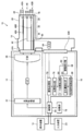
- FIG. 1 conceptually shows an example of an endoscope apparatus of the present invention that implements a method for measuring a volume of a lesioned part of the present invention.
- FIG. 2 is a block diagram showing the internal configuration of the endoscope diagnosis apparatus shown in FIG.
- the endoscope diagnostic apparatus 10 is an endoscope that captures an endoscope image of an observation region of a subject with a light source device 12 and observation light supplied from the light source device 12.
- Mirror 14 processor device 16 that performs image processing on an endoscope image captured by endoscope 14, display device 18 that displays an endoscope image after image processing that is output from processor device 16, and input operation
- an input device 20 that receives
- the light source device 12 includes a light source control unit 22, a laser light source LD, and a duplexer 26.
- a narrow band light having a constant blue wavelength range (for example, center wavelength ⁇ 10 nm) having a center wavelength of 445 nm is emitted from the laser light source LD.
- the laser light source LD is a light source that emits excitation light for generating white light (pseudo white light) from a phosphor that will be described later as illumination light, and is a light source control that is controlled by the control unit 68 of the processor device 16 that will be described later.
- the unit 22 performs on / off (lighting off / on) control and light amount control.
- the laser light source LD a broad area type InGaN laser diode can be used, and an InGaNAs laser diode, a GaNAs laser diode, or the like can also be used.
- the white light source for generating white light is not limited to the combination of excitation light and phosphor, and any light source that emits white light may be used.
- a xenon lamp, a halogen lamp, a white LED (light emitting diode) Etc. can also be used.
- the wavelength of the laser light emitted from the laser light source LD is not limited to the above example, and laser light having a wavelength that plays the same role can be selected as appropriate.
- Laser light emitted from the laser light source LD is incident on the optical fiber via a condenser lens (not shown), is demultiplexed into two systems of light by the demultiplexer 26, and is transmitted to the connector portion 32A.
- the duplexer 26 includes a half mirror, a reflection mirror, and the like.
- the endoscope 14 includes an illumination optical system that emits two systems (two lights) of illumination light from the distal end surface of the insertion portion that is inserted into the subject, and one system that captures an endoscopic image of the observation region ( 1 is an electronic endoscope having an imaging optical system.
- the endoscope 14 includes an insertion unit 28, an operation unit 30 that performs an operation for bending and observing the distal end of the insertion unit 28, and a connector unit 32A that detachably connects the endoscope 14 and the light source device.
- a connector portion 32B for detachably connecting the endoscope 14 and the processor device 16 is provided.
- a water supply connector for connecting the endoscope 14 and the water supply source and an air supply connector for connecting the endoscope 14 and the air supply source are provided on the back surface side of the connector portion 32A in FIG.
- the endoscope 14 is basically a known electronic endoscope except that it corresponds to the volume measurement of a lesioned part to be described later.
- the insertion portion 28 includes a flexible soft portion 34, a bending portion 36, and an endoscope distal end portion 38.
- the bending portion 36 is provided between the flexible portion 34 and the endoscope distal end portion 38 and is configured to be bent by a turning operation of an angle knob 40 disposed in the operation portion 30.
- the bending portion 36 can be bent in an arbitrary direction and an arbitrary angle in accordance with a portion of the subject in which the endoscope 14 is used, and the endoscope distal end portion 38 can be directed to a desired observation portion. it can.
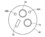
- an endoscope distal end surface 46 which is the distal end surface of the insertion portion 28 (endoscope distal end portion 38), has two illumination windows 42A and 42B for irradiating light to the observation region, One system observation window 44 for imaging reflected light from the observation region, forceps port 74 serving as an outlet of a treatment tool such as forceps inserted into a forceps channel provided inside the insertion portion 28, air supply / water supply An air / water supply port 76 and the like serving as an outlet of the channel 50 are arranged.
- the observation window 44, the forceps port 74, and the air / water supply port 76 are arranged at the center of the endoscope distal end surface 46.
- the illumination windows 42A and 42B are arranged on both sides of the observation window 44.
- the air / water supply port 76 cleans the observation window 44 by jetting water and air.
- the air / water supply port 76 is connected to the air / water supply channel 50.
- the air / water channel 50 is connected from the air / water supply port 76 through the endoscope distal end portion 38, the bending portion 36 and the flexible portion 34 of the insertion portion 28, and the operation portion 30 (air / water supply button 30a). It is connected to the water supply connector and the air supply connector of the connector portion 32A.
- the endoscope 14 supplies air from the air / water supply port 76 of the endoscope distal end surface 46 of the insertion unit 28 by operating the air / water supply button 30a of the operation unit 30. And can carry water.
- air supply and water supply are for cleaning the observation window 44, but the present invention is not limited to this. That is, in the endoscope apparatus of the present invention, the air supply and water supply may be performed by cleaning the observation area, or the function of performing the air supply and water supply for cleaning the observation window 44 and the object to be observed. You may have both the function to perform air supply and water supply for performing washing
- the optical fiber 48A is accommodated in the back of the illumination window 42A.
- the optical fiber 48A is laid on the light source device 12 via the endoscope distal end portion 38 of the insertion portion 28, the bending portion 36 and the flexible portion 34, and the connector portion 32A.
- a phosphor 54A is disposed at the tip of the optical fiber 48A (on the illumination window 42A side), and an optical system such as a lens 52A is attached to the tip of the phosphor 54A.
- an optical fiber 48B having an optical system such as a phosphor 54B and a lens 52B at the tip is housed.
- the phosphors 54A and 54B absorb a part of the blue laser light from the laser light source LD and excite and emit green to yellow, for example, a plurality of types of fluorescent materials (for example, YAG-based fluorescent materials or BAM (BaMgAl 10 O 17 )). A fluorescent substance).
- fluorescent materials for example, YAG-based fluorescent materials or BAM (BaMgAl 10 O 17 )
- BAM BaMgAl 10 O 17
- a fluorescent substance When excitation light for white light observation is irradiated onto the phosphors 54A and 54B, green to yellow excitation emission light (fluorescence) emitted from the phosphors 54A and 54B and the phosphors 54A and 54B are transmitted without being absorbed. Combined with the blue laser light, white light (pseudo white light) is generated.
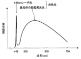
- FIG. 4 is a graph showing an emission spectrum obtained by converting the wavelength of blue laser light and blue laser light from a blue laser light source with a phosphor.
- the blue laser light emitted from the laser light source LD is represented by a bright line having a central wavelength of 445 nm, and the excitation light emitted from the phosphors 54A and 54B by the blue laser light has a spectral intensity whose emission intensity increases in a wavelength range of approximately 450 nm to 700 nm. Intensity distribution.
- the pseudo white light described above is formed by the combined light of the excitation light and the blue laser light.
- the white light referred to in the present invention is not limited to one that strictly includes all wavelength components of visible light.
- the illumination optical systems on the illumination window 42A side and the illumination window 42B side have the same configuration and function, and basically the same illumination light is emitted from the illumination windows 42A and 42B at the same time. Different illumination lights can be irradiated from the illumination windows 42A and 42B. It is not essential to have an illumination optical system that emits two systems of illumination light. For example, an illumination optical system that emits one or four systems of illumination light can realize the same function.
- An optical system such as an objective lens unit 56 for capturing image light of the observation region of the subject is attached to the back of the observation window 44, and further, image information of the observation region is displayed behind the objective lens unit 56.
- An imaging device 58 such as a CCD (Charge-Coupled Device) image sensor or a CMOS (Complementary Metal-Oxide-Semiconductor) image sensor is attached.
- the imaging element 58 receives light from the objective lens unit 56 on the imaging surface (light receiving surface), photoelectrically converts the received light, and outputs an imaging signal (analog signal).
- the R color about 580 nm to 760 nm
- G color about 450 nm to 630 nm
- B color having a spectral transmittance that divides the wavelength range of about 370 to 720 nm of visible light into three parts
- a color filter of about 380 nm to 510 nm is provided, and a plurality of sets of pixels are arranged in a matrix form with a set of three pixels of R, G, and B pixels.
- the light guided from the light source device 12 by the optical fibers 48A and 48B is irradiated from the endoscope distal end portion 38 toward the observation region of the subject. Then, the state of the observation region irradiated with the illumination light is imaged on the imaging surface of the imaging device 58 by the objective lens unit 56, and photoelectrically converted by the imaging device 58 and imaged.
- the imaging element 58 outputs an imaging signal (analog signal) of an endoscopic image of the observed region of the subject that has been imaged.
- the imaging signal (analog signal) of the endoscopic image output from the imaging device 58 is input to the A / D converter 64 through the scope cable 62.
- the A / D converter 64 converts an image signal (analog signal) from the image sensor 58 into an image signal (digital signal).
- the converted image signal is input to the image processing unit 70 of the processor device 16 via the connector unit 32B.
- the processor device 16 includes a control unit 68, an image processing unit 70, a storage unit 72, a position detection unit 78 (corresponding to a position detection unit), a hood volume detection unit 80, and a model detection unit 82 (for the model detection unit). Equivalent), a water injection amount detection unit 84 (corresponding to the water injection amount detection means), and a lesion volume detection unit 86 (corresponding to the lesion volume detection means). Further, the display device 18 and the input device 20 are connected to the control unit 68.
- the processor device 16 controls the light source control unit 22 of the light source device 12 on the basis of an instruction input from the imaging switch of the endoscope 14 or the input device 20, and the endoscope image input from the endoscope 14.
- the image signal is subjected to image processing, and the endoscope image after the image processing is output to the display device 18.
- the processor device 16 may be configured using a computer, for example.
- the image processing unit 70 performs various preset image processing on the image signal of the endoscope image input from the endoscope 14 and outputs the image signal of the endoscope image after the image processing.
- the image signal of the endoscope image after the image processing is sent to the control unit 68.
- the image signal of the endoscopic image after image processing generated by the image processing unit 70 is also supplied to the position detection unit 78.
- the position detection unit 78 detects the position of the distal end portion of the scope hood 90 attached to the endoscope distal end portion 38 of the endoscope 14 from the endoscopic image.
- FIG. 5A shows a conceptual diagram of an example of a scope hood 90 (hereinafter also referred to as a hood 90), and FIG. 5B shows a conceptual diagram of how the hood 90 is attached to the endoscope distal end portion 38.
- the hood 90 is a cylindrical object that can be attached to and detached from the endoscope distal end portion 38, and is used for securing a visual field, securing an appropriate imaging distance from the observed portion, assisting treatment with various treatment tools, and the like.
- various models corresponding to the model of the endoscope 14 are prepared for each model of the endoscope 14.
- any known hood 90 can be used as long as it corresponds to the model of the endoscope 14. Therefore, the hood 90 may be a straight tube or may gradually decrease in diameter from the middle toward the tip.
- the position detection unit 78 captures the position of the distal end of the hood 90 on the endoscopic image (insertion unit) from the endoscopic image captured by the endoscope 14 with the hood 90 and processed by the image processing unit 70. 28) is detected.
- the model detection unit 82 detects the model of the endoscope 14 and / or the model of the hood 90 attached to the distal end portion 38 of the endoscope.
- the hood volume detection unit 80 uses the position of the distal end of the hood 90 detected by the position detection unit 78 and the model of the endoscope 14 and / or the model of the hood 90 detected by the model detection unit 82 to use the endoscope 14.
- the volume of the internal space of the hood 90 formed by the front end surface of the hood 90 and the hood 90 is detected.
- the tip of the hood 90 is usually brought into close contact with the observation region of the subject. That is, in other words, the hood volume detection unit 80 corresponds to the state in which the tip of the hood 90 is in close contact with the observation region of the subject, the tip surface of the endoscope 14, the inner surface of the hood 90, and the subject.
- the volume of the space formed by the surface of the hood 90 that is, the open surface on the front end side of the hood 90 is detected.
- the water injection amount detection unit 84 detects the amount of water injected into the hood 90 when measuring the volume of a lesioned portion described later.
- water for cleaning the observation window 44 can be ejected from the air / water supply port 76 by operating the air / water supply button 30 a.
- water is injected into the inside of the hood 90 attached to the endoscope distal end portion 38 when measuring the volume of a lesion portion described later using this. At this time, the water injection amount detection unit 84 detects the amount of water injection into the hood 90.
- the lesioned part volume detection unit 86 calculates a lesioned part such as a tumor from the difference between the volume of the internal space of the hood 90 detected by the hood volume detection unit 80 and the amount of water injected into the hood 90 extracted by the water injection amount detection unit 84. Is to detect the volume.
- the position detector 78, the hood volume detector 80, the model detector 82, the water injection amount detector 84, and the lesion volume detector 86 will be described in detail later.
- the control unit 68 performs overall control of the endoscope diagnostic apparatus 10 such as display by the display device 18, operation of the light source control unit 22, and image processing by the image processing unit 70. Further, the control unit 68 controls the operation of the light source control unit 22 of the light source device 12 based on an instruction from the imaging switch of the endoscope 14 or the input device 20, or, for example, one (one frame) endoscope
- the mirror image is controlled to be stored in the storage unit 72 as a unit.
- the input device 20 is a known input device configured with a keyboard, a mouse, and the like.
- the display device is also a known display device (display) configured by a liquid crystal display or the like.
- the laser light source LD is turned on with a predetermined light emission amount controlled by the light source control unit 22.
- Laser light having a central wavelength of 445 nm emitted from the laser light source LD is applied to the phosphors 54A and 54B, and white light is emitted from the phosphors 54A and 54B.
- White light emitted from the phosphors 54A and 54B is applied to the subject, and the reflected light is received by the image sensor 58 to capture an endoscopic image of the observation region of the subject.
- the imaging signal (analog signal) of the endoscopic image output from the imaging element 58 is converted into an image signal (digital signal) by the A / D converter 64, and various image processing is performed by the image processing unit 70.
- An image signal of an endoscopic image after image processing is output.
- the control unit 68 displays an endoscopic image corresponding to the image signal of the endoscopic image after image processing on the display device 18, and the image signal of the endoscopic image is stored in the storage unit 72 as necessary. Is remembered.
- the endoscope diagnosis apparatus 10 of the present invention has a function of detecting the volume of a lesioned part such as a tumor in a region to be observed. For example, mode selection such as a volume measurement mode or a switch such as a volume measurement switch is used. In response to the instruction, volume detection of the lesion is performed. In the present invention, the volume detection of the lesioned part is performed using the hood 90 attached to the endoscope distal end part 38 of the insertion part 28 as described above.
- an operator of an endoscope such as a doctor attaches a hood 90 to the endoscope distal end portion 38, inserts the insertion portion 28 into a body cavity, and inserts the endoscope 14 into the body cavity.
- the endoscope distal end portion 38 is brought close to a target observation region such as a place where a lesion portion t such as a tumor of the subject H exists.
- a target observation region such as a place where a lesion portion t such as a tumor of the subject H exists.
- the endoscope distal end portion 38 is brought close to the target observation region, and the tip of the hood 90 is brought into contact with and closely contacted with the observation region of the subject H as conceptually shown in FIG. . Thereby, the observation visual field and imaging distance by the endoscope 14 are ensured by the action of the hood 90.
- an endoscopic image is supplied to the position detection unit 78.
- the model detection unit 82 detects the model of the endoscope 14 and / or the model of the hood 90 attached thereto, and sends the detected information to the hood volume detection unit 80 (corresponding to the spatial volume detection means).
- information on the endoscope 14 is normally supplied from the endoscope 14 to the control unit 68 of the processor device 16 when the connector unit 32 ⁇ / b> A is connected to the processor device 16.
- the model detection unit 82 may detect the model of the endoscope 14 using this information.
- the model of the hood 90 includes, for example, an input means for a user to input the model of the hood 90 by a GUI (graphical user interface) using the input device 20 and the display device 18, and information input from the input means.
- the model detection unit 82 may detect the model of the hood 90.
- the model of the endoscope 14 may be input by a similar method.
- the position detection unit 78 detects the position of the tip of the hood 90 on the endoscopic image from the captured endoscopic image.
- FIG. 7 conceptually shows an endoscopic image captured with the hood 90 attached to the endoscope distal end portion 38. In the endoscopic image captured with the hood 90 attached, the hood 90 is captured.
- the position detection unit 78 detects a hood distal end portion 90a that is the distal end portion of the hood 90 on the image from the endoscopic image.
- the detection of the hood tip 90a may be performed by a known method such as edge detection or circle fitting (pattern matching).
- the position detection result of the hood tip 90 a detected by the position detection unit 78 is supplied to the hood volume detection unit 80.
- the hood volume detection unit 80 is attached with information on the position of the hood tip 90a on the endoscope image supplied from the position detection unit 78 and the model and / or the type of the endoscope 14 supplied from the model detection unit 82.
- the volume of the internal space of the hood 90 formed by the distal end surface of the endoscope 14 and the hood 90 is detected using the information on the model of the hood 90.
- the hood 90 is mounted by fitting an endoscope distal end portion 38 of the insertion portion 28 so that an operator of the endoscope 14 such as a doctor fits.
- the pushing amount of the hood 90 is not necessarily constant. That is, the volume of the internal space of the hood 90 varies depending on the amount of pressing of the hood 90 by the operator.
- the position, the inner peripheral length, the diameter, and the like of the inner periphery of the hood tip 90a on the endoscopic image are uniquely determined according to the pushing amount of the hood 90. That is, when the pushing amount is large, the distance between the endoscope distal end surface 46 and the hood distal end portion 90a becomes closer, so the inner circumference of the hood distal end portion 90a is closer to the outside on the image, and the inner circumferential length and diameter are become longer.
- the pushing amount of the hood 90 can be determined from the position, inner length, diameter, etc. of the inner periphery of the hood tip 90a on the endoscopic image. If the model of the hood 90 is the same, the volume of the internal space of the hood 90 with respect to the pushing amount is uniquely determined.
- the endoscope diagnostic apparatus 10 shows, for each model of the hood 90, for example, the relationship between the inner peripheral length of the hood tip 90a on the endoscopic image and the volume of the internal space of the hood 90.
- An LUT lookup table
- the hood volume detection unit 80 selects a corresponding LUT according to the model information of the hood 90, and determines the inner circumference of the hood tip 90a on the endoscope image from the position of the tip on the endoscope image.
- the length is detected, and the volume of the internal space of the hood 90 is detected from the inner peripheral length using the selected LUT.
- the position, diameter, radius, etc. of the inner periphery of the hood distal end portion 90a on the endoscopic image can be used.
- various methods can be used for detecting the volume of the internal space of the hood 90.
- the model of the endoscope 14 is known, the area, inner peripheral length, diameter, etc. of the endoscope front end face 46 of the endoscope 14 can be known.
- the hood 90 is a straight tube, the size and shape of the endoscope front end face 46 of the endoscope 14 and the hood front end portion 90a are the same. That is, when the hood 90 is a straight tube, if the model of the endoscope 14 is known, similarly, depending on the position of the inner periphery of the hood tip 90a on the endoscope image, the inner periphery length, the diameter, etc.
- the pushing amount of the hood 90 is known. Therefore, similarly, for each model of the endoscope 14, an LUT indicating the relationship between the inner peripheral length of the hood tip 90a on the endoscopic image and the volume of the internal space of the hood 90 is created.
- the corresponding LUT is selected according to the information of the type of the endoscope 14, and the inner peripheral length of the hood distal end portion 90a is detected from the position of the distal end portion on the endoscopic image, and the selected LUT is used.
- the volume of the internal space of the hood 90 may be detected from the inner peripheral length.
- the volume of the internal space of the hood 90 may be detected by calculation other than the method described above.
- the position of the inner periphery, the inner peripheral length, the diameter, and the like of the hood tip 90a on the endoscopic image are uniquely determined according to the pushing amount of the hood 90. That is, the position, inner circumference length, diameter, etc. of the inner periphery of the hood distal end portion 90 a on the endoscopic image, and the distance between the endoscope distal end surface 46 of the insertion portion 28 of the endoscope 14 and the distal end portion of the hood 90. (Hereafter, this distance is also simply referred to as “hood head”).
- the area of the hood tip 90a can be known. Therefore, for each model of the hood 90, for example, an LUT indicating the relationship between the inner peripheral length of the hood tip 90a on the endoscopic image and the hood length is created, and the LUT is selected according to the hood model. (Equivalent to changing the parameter used to detect the volume of the internal space of the scope hood), and detecting the inner peripheral length of the hood tip 90a from the position of the tip on the endoscopic image, The volume of the internal space of the hood 90 may be detected by detecting the hood length from the circumference and integrating the hood length and the area of the hood tip portion 90a. This method can be suitably used when the hood 90 has a straight tube shape.
- the endoscope front end surface 46 of the insertion portion 28 of the endoscope 14 and the hood front end portion 90a have the same size and shape. Further, if the type of the endoscope 14 is known, the area of the endoscope front end surface 46 can be known. Therefore, similarly, for each model of the endoscope 14, for example, an LUT indicating the relationship between the inner peripheral length of the hood tip 90a on the endoscopic image and the hood length is created. The LUT is selected according to the model of the hood (equivalent to changing the parameter used to detect the volume of the internal space of the scope hood), and the inside of the hood tip 90a is determined from the position of the tip on the endoscopic image. The volume of the internal space of the hood 90 may be detected by detecting the circumference, detecting the hood length from the inner circumference, and integrating the hood length and the area of the hood tip 90a.
- the hood volume detection unit 80 supplies the detection result of the volume of the internal space of the hood 90 to the lesion volume detection unit 86.
- a plurality of methods for detecting the volume of the internal space of the various hoods 90 described above may be used together, or a plurality of detection methods may be set so that the operator can select them.
- the operator operates the air / water supply button 30a to inject water into the hood 90 as shown in FIG.
- the start of water injection may be urged by display on the display device 18, audio output, or the like.
- FIG. 6D when the inside of the hood 90 is filled with water, the water injection is terminated.
- the water injection amount detection unit 84 detects the water injection amount to the hood 90 and supplies the detection result of the water injection amount to the lesion volume detection unit 86.
- a flow meter (corresponding to a flow measurement means) is provided somewhere in the air / water supply channel of the insertion section 28, and the amount of water injected into the hood 90 is determined from the flow measurement result by the flow meter. Illustrated.
- a timer (corresponding to a time measurement means) that measures the water injection time is provided, and from the flow rate of the pump and the water injection time measured by the timer, etc. It is also possible to use a method for determining the water injection amount.
- the endoscope diagnosis apparatus 10 may be provided with a tank for storing water for water injection, a weighing scale (corresponding to a weight measuring unit) that measures the weight of the tank before and after water injection, etc. It is also possible to use a method for determining the amount of water injection from the result of weight measurement by this weight scale or the like. Furthermore, for example, a method of providing an input unit for inputting a water injection amount by a GUI using the input device 20 and the display device 18 and using the water injection amount input by the input unit can be used. This method is effectively used when the operator pours water into the hood 90 from a forceps opening or the like using a syringe or the like. A plurality of such water injection amount detection methods may be used in combination, or a plurality of detection methods may be set so that the operator can select them.
- a warning is given by display on the display device 18, voice output, etc. (corresponding to the water injection amount warning means). It may be emitted. Furthermore, in addition to the warning, a display or audio output that prompts the user to redo the volume detection operation of the lesioned part t may be performed.
- the lesion volume detector 86 subtracts the amount of water injected into the hood 90 supplied from the water injection amount detector 84 from the internal volume of the hood 90 supplied from the hood volume detector 80, so that the volume of the lesion t. Is detected. If there is no lesion t such as a tumor, the internal volume of the hood 90 and the amount of water injected into the hood 90 should match. In contrast, when the lesioned part t is present in the observation region of the subject H, the amount of water that can be injected into the hood 90 is reduced by the volume of the lesioned part t. Therefore, the volume of the lesioned part t can be detected by subtracting the amount of water injected into the hood 90 from the internal volume of the hood 90.
- a hood generally used in an endoscope diagnostic apparatus and an endoscope are generally provided without using a special measurement jig or the like.
- the volume of a lesion such as a tumor can be measured using the water injection function.
- the volume of the lesioned part t detected by the lesioned part volume detection unit 86 is supplied to the control unit 68.
- the control unit 68 displays the detection result of the volume of the lesioned part t on the display device 18 (corresponding to the display unit) and stores (records) it in the storage unit 72 (corresponding to the recording unit).
- the detection result of the volume of the lesioned part t is preferably stored in association with a corresponding endoscopic image such as an endoscopic image when the volume detection mode is selected. Further, when the volume of the lesioned part t exceeds a preset threshold value, a warning may be issued by display on the display device 18, sound output, or the like (corresponding to a warning unit).
Landscapes
- Health & Medical Sciences (AREA)
- Life Sciences & Earth Sciences (AREA)
- Surgery (AREA)
- Physics & Mathematics (AREA)
- Engineering & Computer Science (AREA)
- Veterinary Medicine (AREA)
- Molecular Biology (AREA)
- Public Health (AREA)
- Pathology (AREA)
- General Health & Medical Sciences (AREA)
- Biophysics (AREA)
- Biomedical Technology (AREA)
- Heart & Thoracic Surgery (AREA)
- Medical Informatics (AREA)
- Animal Behavior & Ethology (AREA)
- Optics & Photonics (AREA)
- Nuclear Medicine, Radiotherapy & Molecular Imaging (AREA)
- Radiology & Medical Imaging (AREA)
- Dentistry (AREA)
- Oral & Maxillofacial Surgery (AREA)
- Signal Processing (AREA)
- Astronomy & Astrophysics (AREA)
- General Physics & Mathematics (AREA)
- Endoscopes (AREA)
Abstract
特別な処置具を用いることなく、病変部の体積を容易に検出できる病変部の体積測定方法および内視鏡診断装置を提供する。スコープフードを装着した内視鏡を用い、内視鏡が撮像した画像からスコープフードの先端部の位置を検出し、スコープフードの先端部の位置と、内視鏡の機種および/またはスコープフードの機種とから、スコープフードと挿入部の先端面とが形成するスコープフードの内部空間の体積を知見し、スコープフード内に注水して、注水量とスコープフードの内部空間の体積との差から、病変部の体積を検出することにより、この課題を解決する。
Description
本発明は、内視鏡を用いた病変部の体積測定に関する。詳しくは、特別な測定用の処置具を用いることなく、内視鏡によって容易に病変部の体積の測定を行うことを可能にする内視鏡診断装置および病変部の体積測定方法に関する。
被検体内を観察するために、内視鏡診断装置が用いられている。被検体内の観察を行う場合、内視鏡の挿入部が被検体の体腔内に挿入されて、その先端部から、例えば、観察光として白色光が被観察領域に照射され、その反射光を受光して内視鏡画像が撮像される。撮像された内視鏡画像は表示部に表示され、内視鏡診断装置の操作者により、内視鏡画像の観察が行われる。
近年では、被検体内で撮像された内視鏡画像を見て、腫瘍等の病変部の有無を確認するだけでなく、あるサイズ(大きさ)を超える腫瘍は切除し、それ以下のサイズの腫瘍は温存して様子を見るなどの目的から、病変部のサイズを測定したいという要求がある。
病変部のサイズを測定するために、スケール付きプローブ等の処置具を利用する方法が知られている。この方法では、内視鏡の鉗子口の入口からスケール付きプローブを挿入して先端部の鉗子口の出口から突出させる。スケール付きプローブの先端部は、柔軟性を有し、かつ、サイズを測定するための目盛りが刻まれている。このような柔軟性のある先端部を被観察領域に押し当てて折り曲げ、先端部に刻まれた目盛りを読み取ることにより、被観察領域の病変部のサイズを測定する。
しかし、この方法では、病変部のサイズを測定するためだけに、スケール付きプローブを内視鏡の鉗子口に挿入する必要があるため、その操作に時間がかかるだけでなく、作業が繁雑で面倒であった。また、スケール付きプローブの先端部を被検体の被観察領域に押し当てて折り曲げて測定するため、測定精度が低く、部位によっては、先端部を被検体の被観察領域に押し当てることが難しいなど、測定しづらい場合があった。
また、内視鏡を用いた病変部のサイズの測定方法は、各種の方法が提案されている。
例えば、特許文献1には、内視鏡の挿入部の先端部の2つ開口から病変部に水流を噴射し、2つの水流間の距離が2つの開口間の距離と等しいことから、病変部が処置基準値以上であるか否かを判定することが記載されている。
また、特許文献2には、測定点を設定するためのアーム部を有する処置具を用いて、病変部の周囲に複数の測定点を設定し、測定点の座標情報に基づき、演算により病変部の大きさを求めることが記載されている。
例えば、特許文献1には、内視鏡の挿入部の先端部の2つ開口から病変部に水流を噴射し、2つの水流間の距離が2つの開口間の距離と等しいことから、病変部が処置基準値以上であるか否かを判定することが記載されている。
また、特許文献2には、測定点を設定するためのアーム部を有する処置具を用いて、病変部の周囲に複数の測定点を設定し、測定点の座標情報に基づき、演算により病変部の大きさを求めることが記載されている。
特許文献1の内視鏡装置では、挿入部の先端部から2つの水流を出力する2つの開口を備える専用の内視鏡が必要であり、この内視鏡でなければ病変部のサイズを測定することができないという問題がある。
また、特許文献2の内視鏡装置では、病変部のサイズを測定するために、ロボットアームが必要であり、さらに、煩雑なロボットアームを操作して病変部の周囲に複数の測定点を設定しなければならないという問題がある。
また、特許文献2の内視鏡装置では、病変部のサイズを測定するために、ロボットアームが必要であり、さらに、煩雑なロボットアームを操作して病変部の周囲に複数の測定点を設定しなければならないという問題がある。
本発明の目的は、従来技術の問題点を解消することにあり、測定用の特別な処置具を用いることなく、内視鏡によって腫瘍等の病変部の体積を測定することができる、内視鏡診断装置および病変部の体積測定方法を提供することにある。
上記目的を達成するために、本発明の一態様に係る内視鏡診断装置は、挿入部の先端から注水する機能を有する内視鏡と、
挿入部の先端からの注水量を検出する注水量検出手段と、
内視鏡の挿入部の先端に装着されるスコープフードと、
内視鏡が撮像した画像から、画像上におけるスコープフードの先端部の位置を検出する位置検出手段と、
内視鏡の機種およびスコープフードの機種の少なくとも一方を検出する機種検出手段と、
位置検出手段が検出したスコープフードの先端部の位置、ならびに、機種検出手段が検出した内視鏡の機種およびスコープフードの機種の少なくとも一方を用いて、内視鏡の挿入部の先端面とスコープフードとが形成するスコープフードの内部空間の体積を検出する空間体積検出手段と、
注水量検出手段が検出した注水量と、空間体積検出手段が検出したスコープフードの内部空間の体積とから、病変部の体積を検出する病変部体積検出手段とを有することを特徴とする内視鏡診断装置を提供する。
本発明の一態様に係る内視鏡診断装置において、空間体積検出手段は、スコープフードの機種に応じて作成した、画像上におけるスコープフードの先端部と、スコープフードの内部空間の体積との関係を用いて、スコープフードの内部空間の体積を検出するのが好ましい。
また、本発明の一態様に係る内視鏡診断装置において、空間体積検出手段は、スコープフードの先端部の位置から、内視鏡の挿入部の先端面からスコープフードの先端部までの距離を検出し、かつ、内視鏡の機種およびスコープフードの機種の少なくとも一方から、内視鏡の挿入部の先端面の面積もしくはスコープフードの先端面の面積を検出し、検出した、内視鏡の挿入部の先端面からスコープフードの先端部までの距離と、内視鏡の挿入部の先端面の面積もしくはスコープフードの先端面の面積とを用いて、スコープフードの内部空間の体積を検出するのが好ましい。
また、本発明の一態様に係る内視鏡診断装置において、空間体積検出手段は、内視鏡の機種およびスコープフードの機種の少なくとも一方に応じて、スコープフードの内部空間の体積を検出するために用いるパラメータを変更するのが好ましい。
また、本発明の一態様に係る内視鏡診断装置において、内視鏡が注水した水の流量を測定する流量測定手段、内視鏡が注水する水を貯留するタンクおよびタンクの重量を測定する重量測定手段、内視鏡による水の注水時間を測定する時間測定手段、および、注水量を入力する入力手段のいずれか1つ以上を有し、注水量検出手段は、流量測定手段による水の流量の測定結果、重量測定手段による重量測定結果、時間測定手段による時間測定結果、および、入力手段によって入力された注水量の少なくとも1つを用いて、内視鏡の挿入部の先端からの注水量を検出するのが好ましい。
また、本発明の一態様に係る内視鏡診断装置において、病変部体積検出手段が検出した病変部の体積を表示する表示手段、病変部体積検出手段が検出した病変部の体積を記録する記録手段、および、病変部体積検出手段が検出した病変部の体積に応じた警告を出力する警告手段の少なくとも1つ以上を有するのが好ましい。
さらに、本発明の一態様に係る内視鏡診断装置において、注水量測定手段が検出した注水量が、空間体積検出手段が検出したスコープフードの内部空間の体積を超えた場合に、警告を出力する注水量警告手段を有するのが好ましい。
また、本発明の一態様に係る病変部の体積測定方法は、挿入部の先端にスコープフードを装着した内視鏡を用い、
内視鏡が撮像した画像から、画像上におけるスコープフードの先端部の位置を検出し、
画像上におけるスコープフードの先端部の位置と、内視鏡の機種およびスコープフードの機種の少なくとも一方とから、スコープフードと内視鏡の挿入部の先端面とが形成するスコープフードの内部空間の体積を得て、
スコープフードの内部が満たされるまで注水して、注水量と、スコープフードの内部空間の体積との差から、病変部の体積を測定する、病変部の体積測定方法を提供する。
内視鏡が撮像した画像から、画像上におけるスコープフードの先端部の位置を検出し、
画像上におけるスコープフードの先端部の位置と、内視鏡の機種およびスコープフードの機種の少なくとも一方とから、スコープフードと内視鏡の挿入部の先端面とが形成するスコープフードの内部空間の体積を得て、
スコープフードの内部が満たされるまで注水して、注水量と、スコープフードの内部空間の体積との差から、病変部の体積を測定する、病変部の体積測定方法を提供する。
このような本発明の一態様に係る病変部の体積測定方法において、スコープフードの機種に応じて作成した、画像上におけるスコープフードの先端部と、スコープフードの内部空間の体積との関係を用いて、スコープフードの内部空間の体積を得るのが好ましい。
また、本発明の一態様に係る病変部の体積測定方法において、画像上におけるスコープフードの先端部の位置から、内視鏡の先端面からスコープフードの先端部までの距離を検出し、内視鏡の機種およびスコープフードの機種の少なくとも一方から、内視鏡の先端面の面積もしくはスコープフードの先端面の面積を検出し、内視鏡の先端面からスコープフードの先端部までの距離と、内視鏡の先端面の面積もしくはスコープフードの先端面の面積とを用いて、スコープフードの内部空間の体積を得るのが好ましい。
また、本発明の一態様に係る病変部の体積測定方法において、内視鏡の機種およびスコープフードの機種の少なくとも一方に応じて、スコープフードの内部空間の体積を得るために用いるパラメータを変更するのが好ましい。
また、本発明の一態様に係る病変部の体積測定方法において、スコープフード内部への注水量を、内視鏡に取り付けた水の流量測定装置、内視鏡が注水する水を貯留したタンクの重量変化、スコープフードへの注水時間、および、注水量の入力のいずれか1つ以上を用いて検出するのが好ましい。
また、本発明の一態様に係る病変部の体積測定方法において、測定した病変部の体積の表示、測定した病変部の体積の記録、および、測定した病変部の体積に応じた警告の出力のいずれか1つ以上を行うのが好ましい。
さらに、本発明の一態様に係る病変部の体積測定方法において、スコープフードの内部空間の体積よりも、スコープフード内への注水量が多くなった場合に、警告を出力するのが好ましい。
本発明によれば特別な治具を用いることなく、内視鏡の処置具として一般的に用いられるスコープフードと、内視鏡が一般的に有する注水機能とを用いて、腫瘍等の病変部の体積を容易に測定できる。
以下、本発明の内視鏡診断装置および病変部の体積測定方法について、添付の図面に示される好適実施例を基に、詳細に説明する。
図1に、本発明の病変部の体積測定方法を実施する本発明の内視鏡装置の一例を概念的に示す。また、図2に、図1に示す内視鏡診断装置の内部構成をブロック図で示す。
図1および図2に示されるように、内視鏡診断装置10は、光源装置12と、光源装置12から供給された観察光によって被検体の被観察領域の内視鏡画像を撮像する内視鏡14と、内視鏡14で撮像された内視鏡画像を画像処理するプロセッサ装置16と、プロセッサ装置16から出力される画像処理後の内視鏡画像を表示する表示装置18と、入力操作を受け付ける入力装置20とによって構成されている。
図1および図2に示されるように、内視鏡診断装置10は、光源装置12と、光源装置12から供給された観察光によって被検体の被観察領域の内視鏡画像を撮像する内視鏡14と、内視鏡14で撮像された内視鏡画像を画像処理するプロセッサ装置16と、プロセッサ装置16から出力される画像処理後の内視鏡画像を表示する表示装置18と、入力操作を受け付ける入力装置20とによって構成されている。
図2に示すように、光源装置12は、光源制御部22と、レーザ光源LDと、分波器26とによって構成されている。
図示例の光源装置12においては、レーザ光源LDから、中心波長が445nmである、青色の一定の波長範囲(例えば、中心波長±10nm)の狭帯域光が発せられる。レーザ光源LDは、照明光として、後述する蛍光体から白色光(疑似白色光)を発生させるための励起光を発する光源であって、後述するプロセッサ装置16の制御部68によって制御される光源制御部22によりオンオフ(点灯消灯)制御および光量制御が行われる。
レーザ光源LDとしては、ブロードエリア型のInGaN系レーザダイオードが利用でき、また、InGaNAs系レーザダイオードやGaNAs系レーザダイオード等を用いることもできる。
なお、白色光を発生するための白色光光源は、励起光および蛍光体の組合せに限定されず、白色光を発するものであればよく、例えば、キセノンランプ、ハロゲンランプ、白色LED(発光ダイオード)などを利用することもできる。また、レーザ光源LDから発せられるレーザ光の波長は上記例に限定されず、同様の役割を果たす波長のレーザ光を適宜選択することができる。
レーザ光源LDから発せられるレーザ光は、集光レンズ(図示省略)を介して光ファイバに入射され、分波器26によって2系統の光に分波されてコネクタ部32Aに伝送される。分波器26は、ハーフミラー、反射ミラー等によって構成される。
内視鏡14は、被検体内に挿入される挿入部の先端面から2系統(2灯)の照明光を出射する照明光学系と、被観察領域の内視鏡画像を撮像する1系統(1眼)の撮像光学系とを有する、電子内視鏡である。
内視鏡14は、挿入部28と、挿入部28の先端の湾曲操作や観察のための操作を行う操作部30と、内視鏡14と光源装置とを着脱自在に接続するコネクタ部32Aと、内視鏡14とプロセッサ装置16とを着脱自在に接続するコネクタ部32Bとを備えている。
コネクタ部32Aの図1の裏面側には、内視鏡14と送水源とを接続する送水コネクタ、および、内視鏡14と送気源とを接続する送気コネクタが設けられる。
内視鏡14は、後述する病変部の体積測定に対応する以外は、基本的に、公知の電子内視鏡である。
内視鏡14は、挿入部28と、挿入部28の先端の湾曲操作や観察のための操作を行う操作部30と、内視鏡14と光源装置とを着脱自在に接続するコネクタ部32Aと、内視鏡14とプロセッサ装置16とを着脱自在に接続するコネクタ部32Bとを備えている。
コネクタ部32Aの図1の裏面側には、内視鏡14と送水源とを接続する送水コネクタ、および、内視鏡14と送気源とを接続する送気コネクタが設けられる。
内視鏡14は、後述する病変部の体積測定に対応する以外は、基本的に、公知の電子内視鏡である。
挿入部28は、可撓性を持つ軟性部34と、湾曲部36と、内視鏡先端部38とから構成されている。
湾曲部36は、軟性部34と内視鏡先端部38との間に設けられ、操作部30に配置されたアングルノブ40の回動操作により湾曲自在に構成されている。この湾曲部36は、内視鏡14が使用される被検体の部位等に応じて、任意の方向、任意の角度に湾曲でき、内視鏡先端部38を、所望の観察部位に向けることができる。
図3に示すように、挿入部28(内視鏡先端部38)の先端面である内視鏡先端面46には、被観察領域へ光を照射する2系統の照明窓42A、42B、被観察領域からの反射光を撮像する1系統の観察窓44、挿入部28の内部に設けられている鉗子チャンネルに挿入される鉗子等の処置具等の出口となる鉗子口74、送気・送水チャンネル50の出口となる送気・送水口76等が配置されている。
観察窓44、鉗子口74、送気・送水口76は、内視鏡先端面46の中央部に配置されている。照明窓42A、42Bは、観察窓44を挟んでその両脇側に配置されている。
送気・送水口76は、水および空気を噴射することで、観察窓44を洗浄するものである。送気・送水口76は、送気・送水チャンネル50に接続される。送気・送水チャンネル50は、送気・送水口76から、挿入部28の内視鏡先端部38、湾曲部36および軟性部34、操作部30(送気・送水ボタン30a)を介して、コネクタ部32Aの送水コネクタおよび送気コネクタに接続される。
通常の内視鏡と同様、内視鏡14は、操作部30の送気・送水ボタン30aを操作することにより、挿入部28の内視鏡先端面46の送気・送水口76から送気および送水を行うことができる。
なお、図示例の内視鏡14において、送気および送水は、観察窓44を洗浄するためのものであるが、本発明は、これに限定はされない。すなわち、本発明の内視鏡装置において、送気および送水は、被観察領域の洗浄等を行うものでもよく、あるいは、観察窓44を洗浄するための送気および送水を行う機能と、被観察領域の洗浄等を行うための送気および送水を行う機能との両方を有するものでもよい。
通常の内視鏡と同様、内視鏡14は、操作部30の送気・送水ボタン30aを操作することにより、挿入部28の内視鏡先端面46の送気・送水口76から送気および送水を行うことができる。
なお、図示例の内視鏡14において、送気および送水は、観察窓44を洗浄するためのものであるが、本発明は、これに限定はされない。すなわち、本発明の内視鏡装置において、送気および送水は、被観察領域の洗浄等を行うものでもよく、あるいは、観察窓44を洗浄するための送気および送水を行う機能と、被観察領域の洗浄等を行うための送気および送水を行う機能との両方を有するものでもよい。
照明窓42Aの奥には、光ファイバ48Aが収納されている。光ファイバ48Aは、挿入部28の内視鏡先端部38、湾曲部36および軟性部34、および、コネクタ部32Aを介して、光源装置12に敷設されている。光ファイバ48Aの先端部(照明窓42A側)の先には蛍光体54Aが配置され、さらに蛍光体54Aの先にレンズ52A等の光学系が取り付けられている。同様に、照明窓42Bの奥には、先端部に蛍光体54Bおよびレンズ52B等の光学系を有する光ファイバ48Bが収納されている。
蛍光体54A、54Bは、レーザ光源LDからの青色レーザ光の一部を吸収して緑色~黄色に励起発光する複数種の蛍光物質(例えばYAG系蛍光物質、或いはBAM(BaMgAl10O17)等の蛍光物質)を含んで構成される。白色光観察用の励起光が蛍光体54A、54Bに照射されると、蛍光体54A、54Bから発せられる緑色~黄色の励起発光光(蛍光)と、蛍光体54A、54Bにより吸収されず透過した青色レーザ光とが合わされて、白色光(疑似白色光)が生成される。
図4は、青色レーザ光源からの青色レーザ光及び青色レーザ光が蛍光体により波長変換された発光スペクトルを示すグラフである。レーザ光源LDから発せられる青色レーザ光は、中心波長445nmの輝線で表され、青色レーザ光による蛍光体54A、54Bからの励起発光光は、概ね450nm~700nmの波長範囲で発光強度が増大する分光強度分布となる。この励起発光光と青色レーザ光との合波光によって、上述した疑似白色光が形成される。
ここで、本発明でいう白色光とは、厳密に可視光の全ての波長成分を含むものに限らず、例えば、上述した疑似白色光を始めとして、基準色であるR(赤)、G(緑)、B(青)等、特定の波長帯の光を含むものであればよい。つまり、本発明のいう白色光には、例えば、緑色から赤色にかけての波長成分を含む光や、青色から緑色にかけての波長成分を含む光等も広義に含まれるものとする。
照明窓42A側および照明窓42B側の照明光学系は同等の構成および作用のものであって、照明窓42A、42Bからは、基本的に同時に同等の照明光が照射される。なお、照明窓42A、42Bからそれぞれ異なる照明光を照射させることもできる。また、2系統の照明光を出射する照明光学系を有することは必須ではなく、例えば、1系統や4系統の照明光を出射する照明光学系でも同等の機能を実現することができる。
観察窓44の奥には、被検体の被観察領域の像光を取り込むための対物レンズユニット56等の光学系が取り付けられ、さらに対物レンズユニット56の奥には、被観察領域の画像情報を取得するCCD(Charge Coupled Device)イメージセンサやCMOS(Complementary Metal-Oxide Semiconductor)イメージセンサ等の撮像素子58が取り付けられている。
撮像素子58は、対物レンズユニット56からの光を撮像面(受光面)で受光し、受光した光を光電変換して撮像信号(アナログ信号)を出力する。撮像素子58の撮像面には、可視光の約370~720nmの波長範囲を3分割する分光透過率を有する、R色(約580nm~760nm)、G色(約450nm~630nm)、B色(約380nm~510nm)のカラーフィルタが設けられ、R画素、G画素、B画素の3色の画素を1組として、複数組の画素がマトリクス状に配列されている。
光源装置12から光ファイバ48A、48Bによって導光された光は、内視鏡先端部38から被検体の被観察領域に向けて照射される。そして、照明光が照射された被観察領域の様子が対物レンズユニット56により撮像素子58の撮像面上に結像され、撮像素子58により光電変換されて撮像される。撮像素子58からは、撮像された被検体の被観察領域の内視鏡画像の撮像信号(アナログ信号)が出力される。
撮像素子58から出力される内視鏡画像の撮像信号(アナログ信号)は、スコープケーブル62を通じてA/D変換器64に入力される。A/D変換器64は、撮像素子58からの撮像信号(アナログ信号)を画像信号(デジタル信号)に変換する。変換後の画像信号は、コネクタ部32Bを介してプロセッサ装置16の画像処理部70に入力される。
プロセッサ装置16は、制御部68と、画像処理部70と、記憶部72と、位置検出部78(位置検出手段に相当)と、フード体積検出部80と、機種検出部82(機種検出手段に相当)と、注水量検出部84(注水量検出手段に相当)と、病変部体積検出部86(病変部体積検出手段に相当)とを備えている。また、制御部68には、表示装置18および入力装置20が接続されている。プロセッサ装置16は、内視鏡14の撮像スイッチや入力装置20から入力される指示に基づき、光源装置12の光源制御部22を制御するとともに、内視鏡14から入力される内視鏡画像の画像信号を画像処理し、画像処理後の内視鏡画像を表示装置18に出力する。
プロセッサ装置16は、例えば、コンピュータを利用して構成すればよい。
プロセッサ装置16は、例えば、コンピュータを利用して構成すればよい。
画像処理部70は、内視鏡14から入力される内視鏡画像の画像信号に対してあらかじめ設定された各種の画像処理を施し、画像処理後の内視鏡画像の画像信号を出力する。画像処理後の内視鏡画像の画像信号は、制御部68に送られる。
また、後述する病変部の体積測定を行う場合には、画像処理部70が生成した画像処理後の内視鏡画像の画像信号は、位置検出部78にも供給される。
また、後述する病変部の体積測定を行う場合には、画像処理部70が生成した画像処理後の内視鏡画像の画像信号は、位置検出部78にも供給される。
位置検出部78は、内視鏡画像から、内視鏡14の内視鏡先端部38に装着されたスコープフード90の先端部の位置を検出するものである。
図5(A)に、スコープフード90(以下、フード90とも言う)の一例の概念図を、図5(B)に、フード90を内視鏡先端部38に装着する様子の概念図を示す。
フード90は、内視鏡先端部38に着脱自在な筒状物であり、視野の確保、被観察部との適正な撮像距離の確保、各種の処置具による処置の補助等のために用いられる。
このようなフード90は、内視鏡14の機種毎に、内視鏡14の機種に対応する様々な機種が用意されている。本発明においては、内視鏡14の機種に応じたものであれば、公知のフード90が、全て利用可能である。従って、フード90は、直管状のものであっても、途中から先端に向けて、漸次、縮径するものであってもよい。
フード90は、内視鏡先端部38に着脱自在な筒状物であり、視野の確保、被観察部との適正な撮像距離の確保、各種の処置具による処置の補助等のために用いられる。
このようなフード90は、内視鏡14の機種毎に、内視鏡14の機種に対応する様々な機種が用意されている。本発明においては、内視鏡14の機種に応じたものであれば、公知のフード90が、全て利用可能である。従って、フード90は、直管状のものであっても、途中から先端に向けて、漸次、縮径するものであってもよい。
位置検出部78は、フード90を装着した内視鏡14が撮像して、画像処理部70が処理した内視鏡画像から、この内視鏡画像上におけるフード90の先端部の位置(挿入部28とは逆側の端部)を検出する。
機種検出部82は、内視鏡14の機種、および/または、内視鏡先端部38に装着されたフード90の機種を検出するものである。
フード体積検出部80は、位置検出部78が検出したフード90の先端位置と、機種検出部82が検出した内視鏡14の機種および/またはフード90の機種とを用いて、内視鏡14の先端面とフード90とが形成する、フード90の内部空間の体積を検出するものである。
フード90を用いた内視鏡14での観察時には、通常、フード90の先端を被検体の被観察領域に密着する。すなわち、言い換えれば、フード体積検出部80は、フード90の先端が被検体の被観察領域に密着された状態に対応して、内視鏡14の先端面と、フード90の内面と、被検体の表面すなわちフード90の先端側の開放面とで構成される空間の体積を検出する。
フード90を用いた内視鏡14での観察時には、通常、フード90の先端を被検体の被観察領域に密着する。すなわち、言い換えれば、フード体積検出部80は、フード90の先端が被検体の被観察領域に密着された状態に対応して、内視鏡14の先端面と、フード90の内面と、被検体の表面すなわちフード90の先端側の開放面とで構成される空間の体積を検出する。
注水量検出部84は、後述する病変部の体積測定を行う場合に、フード90の内部に注水された注水量を検出するものである。
前述のように、内視鏡14では、送気・送水ボタン30aを操作することにより、送気・送水口76から、観察窓44を洗浄するための水を噴射できる。本発明の内視鏡診断装置10においては、これを利用して、後述する病変部の体積測定を行う場合に、内視鏡先端部38に装着されたフード90の内部に注水を行う。注水量検出部84は、この際に、フード90の内部への注水量を検出する。
前述のように、内視鏡14では、送気・送水ボタン30aを操作することにより、送気・送水口76から、観察窓44を洗浄するための水を噴射できる。本発明の内視鏡診断装置10においては、これを利用して、後述する病変部の体積測定を行う場合に、内視鏡先端部38に装着されたフード90の内部に注水を行う。注水量検出部84は、この際に、フード90の内部への注水量を検出する。
病変部体積検出部86は、フード体積検出部80が検出したフード90の内部空間の体積と、注水量検出部84が抽出したフード90内部への注水量との差から、腫瘍等の病変部の体積を検出するものである。
位置検出部78、フード体積検出部80、機種検出部82、注水量検出部84、および、病変部体積検出部86については、後に詳述する。
位置検出部78、フード体積検出部80、機種検出部82、注水量検出部84、および、病変部体積検出部86については、後に詳述する。
制御部68は、表示装置18による表示、光源制御部22の動作、画像処理部70による画像処理など、内視鏡診断装置10の全体の制御を行うものである。また、制御部68は、内視鏡14の撮像スイッチや入力装置20からの指示に基づいて、光源装置12の光源制御部22の動作を制御したり、例えば1枚(1フレーム)の内視鏡画像を単位として記憶部72に記憶するように制御したりする。
入力装置20は、キーボードやマウス等で構成される、公知の入力装置である。表示装置も液晶ディスプレイ等で構成される、公知の表示装置(ディスプレイ)である。
入力装置20は、キーボードやマウス等で構成される、公知の入力装置である。表示装置も液晶ディスプレイ等で構成される、公知の表示装置(ディスプレイ)である。
以下、内視鏡診断装置10の作用を説明することにより、本発明の内視鏡診断装置および病変部の体積測定方法を詳細に説明する。
まず、内視鏡画像を撮像する場合の動作を説明する。
通常の内視鏡画像の撮像時には、光源制御部22の制御により、レーザ光源LDが予め設定された一定の発光量で点灯される。レーザ光源LDから発せられる中心波長445nmのレーザ光が蛍光体54A、54Bに照射され、蛍光体54A、54Bから白色光が発せられる。蛍光体54A、54Bから発せられる白色光は被検体に照射され、その反射光が撮像素子58で受光されて被検体の被観察領域の内視鏡画像が撮像される。
通常の内視鏡画像の撮像時には、光源制御部22の制御により、レーザ光源LDが予め設定された一定の発光量で点灯される。レーザ光源LDから発せられる中心波長445nmのレーザ光が蛍光体54A、54Bに照射され、蛍光体54A、54Bから白色光が発せられる。蛍光体54A、54Bから発せられる白色光は被検体に照射され、その反射光が撮像素子58で受光されて被検体の被観察領域の内視鏡画像が撮像される。
撮像素子58から出力される内視鏡画像の撮像信号(アナログ信号)は、A/D変換器64により画像信号(デジタル信号)に変換され、画像処理部70により各種の画像処理が施され、画像処理後の内視鏡画像の画像信号が出力される。そして、制御部68により、画像処理後の内視鏡画像の画像信号に対応する内視鏡画像が表示装置18上に表示され、必要に応じて、内視鏡画像の画像信号が記憶部72に記憶される。
本発明の内視鏡診断装置10は、被観察領域の腫瘍等の病変部の体積の検出を行う機能を有しており、例えば体積測定モード等のモード選択や、体積測定スイッチ等のスイッチでの指示で、病変部の体積検出が行われる。
本発明において、病変部の体積検出は、前述のように挿入部28の内視鏡先端部38に装着されるフード90を用いて行う。
病変部の体積検出を行う際には、医師等の内視鏡の操作者が内視鏡先端部38にフード90を装着して、挿入部28を体腔に挿入して、内視鏡14を操作し、図6(A)に概念的に示すように、被検体Hの腫瘍などの病変部tが有る場所など、目的とする被観察領域に内視鏡先端部38を近付ける。この間には、前述のように、被検体の被観察領域の内視鏡画像が撮像され、表示装置18に表示されている。
本発明において、病変部の体積検出は、前述のように挿入部28の内視鏡先端部38に装着されるフード90を用いて行う。
病変部の体積検出を行う際には、医師等の内視鏡の操作者が内視鏡先端部38にフード90を装着して、挿入部28を体腔に挿入して、内視鏡14を操作し、図6(A)に概念的に示すように、被検体Hの腫瘍などの病変部tが有る場所など、目的とする被観察領域に内視鏡先端部38を近付ける。この間には、前述のように、被検体の被観察領域の内視鏡画像が撮像され、表示装置18に表示されている。
さらに、内視鏡先端部38を目的とする被観察領域に近付け、図6(B)に概念的に示すように、フード90の先端を被検体Hの被観察領域に当接して、密着する。これにより、フード90の作用によって、内視鏡14による観察視野および撮像距離が確保される。
この状態で、例えば体積測定モードが選択されると、内視鏡画像が位置検出部78に供給される。
また、機種検出部82が、内視鏡14の機種および/または装着されたフード90の機種を検出し、検出した情報を、フード体積検出部80(空間体積検出手段に相当)に送る。内視鏡診断装置10では、通常、コネクタ部32Aをプロセッサ装置16に接続した時点で、内視鏡14からプロセッサ装置16の制御部68に、内視鏡14の情報が供給される。機種検出部82は、この情報を用いて、内視鏡14の機種を検出すればよい。また、フード90の機種は、例えば、入力装置20および表示装置18を用いたGUI(graphical user interface)によって、ユーザがフード90の機種を入力する入力手段を設け、この入力手段から入力された情報によって、機種検出部82がフード90の機種を検出するようにすればよい。内視鏡14の機種も、同様の方法で入力可能にしてもよい。
また、機種検出部82が、内視鏡14の機種および/または装着されたフード90の機種を検出し、検出した情報を、フード体積検出部80(空間体積検出手段に相当)に送る。内視鏡診断装置10では、通常、コネクタ部32Aをプロセッサ装置16に接続した時点で、内視鏡14からプロセッサ装置16の制御部68に、内視鏡14の情報が供給される。機種検出部82は、この情報を用いて、内視鏡14の機種を検出すればよい。また、フード90の機種は、例えば、入力装置20および表示装置18を用いたGUI(graphical user interface)によって、ユーザがフード90の機種を入力する入力手段を設け、この入力手段から入力された情報によって、機種検出部82がフード90の機種を検出するようにすればよい。内視鏡14の機種も、同様の方法で入力可能にしてもよい。
位置検出部78は、撮像された内視鏡画像から、内視鏡画像上におけるフード90の先端部の位置を検出する。
図7に、内視鏡先端部38にフード90を装着した状態で撮像された内視鏡画像を概念的に示す。フード90を装着した状態で撮像された内視鏡画像では、フード90が撮像される。位置検出部78は、内視鏡画像から、画像上におけるフード90の先端部であるフード先端部90aを検出する。フード先端部90aの検出は、エッジ検出や円のフィッティング(パターンマッチング)等の公知の方法で行えばよい。
図7に、内視鏡先端部38にフード90を装着した状態で撮像された内視鏡画像を概念的に示す。フード90を装着した状態で撮像された内視鏡画像では、フード90が撮像される。位置検出部78は、内視鏡画像から、画像上におけるフード90の先端部であるフード先端部90aを検出する。フード先端部90aの検出は、エッジ検出や円のフィッティング(パターンマッチング)等の公知の方法で行えばよい。
位置検出部78が検出したフード先端部90aの位置検出結果は、フード体積検出部80に供給される。
フード体積検出部80は、位置検出部78から供給された内視鏡画像上におけるフード先端部90aの位置の情報と、機種検出部82から供給された内視鏡14の機種および/または装着されたフード90の機種の情報を用いて、内視鏡14の先端面とフード90とが形成する、フード90の内部空間の体積を検出する。
フード体積検出部80は、位置検出部78から供給された内視鏡画像上におけるフード先端部90aの位置の情報と、機種検出部82から供給された内視鏡14の機種および/または装着されたフード90の機種の情報を用いて、内視鏡14の先端面とフード90とが形成する、フード90の内部空間の体積を検出する。
周知のように、フード90は、医師等の内視鏡14の操作者が、挿入部28の内視鏡先端部38を被嵌するように嵌合することで装着する。
この際におけるフード90の押込み量は、必ずしも一定ではない。すなわち、フード90の内部空間の体積は、操作者によるフード90の押込み量によって異なる。
この際におけるフード90の押込み量は、必ずしも一定ではない。すなわち、フード90の内部空間の体積は、操作者によるフード90の押込み量によって異なる。
ここで、同じフード90であれば、内視鏡画像上におけるフード先端部90aの内周の位置、内周長、直径等は、フード90の押込み量に応じて、一義的に決まる。すなわち、押込み量が多い場合には、内視鏡先端面46とフード先端部90aとの距離が近くなるので、フード先端部90aの内周は画像上では外側に寄り、内周長や直径は長くなる。逆に、押込み量が少ない場合には、内視鏡先端面46とフード先端部90aとの距離が遠くなるので、フード先端部90aの内周は画像上では内側に寄り、内周長や直径は短くなる。
従って、フード90の機種が分かれば、内視鏡画像上におけるフード先端部90aの内周の位置、内周長、直径等によって、フード90の押込み量が分かる。また、フード90の機種が同じであれば、押込み量に対するフード90の内部空間の体積は、一義的に決まる。
これ対応して、内視鏡診断装置10では、フード90の機種毎に、例えば、内視鏡画像上におけるフード先端部90aの内周長と、フード90の内部空間の体積との関係を示すLUT(ルックアップテーブル)を作成して、フード体積検出部80に記憶しておく。フード体積検出部80は、フード90の機種の情報に応じて、対応するLUTを選択すると共に、内視鏡画像上における先端部の位置から、内視鏡画像上におけるフード先端部90aの内周長を検出して、選択したLUTを用いて、内周長からフード90の内部空間の体積を検出する。
また、フード先端部90aの内周長に変えて、内視鏡画像上におけるフード先端部90aの内周の位置、直径、半径等も利用可能である。
フード90の内部空間の体積の検出は、これ以外にも、各種の方法が利用可能である。
例えば、内視鏡14の機種が分かれば、内視鏡14の内視鏡先端面46の面積、内周長、直径等が分かる。さらに、フード90が直管状である場合には、内視鏡14の内視鏡先端面46と、フード先端部90aとは、サイズおよび形状が一致する。
すなわち、フード90が直管状である場合には、内視鏡14の機種が分かれば、同様に、内視鏡画像上におけるフード先端部90aの内周の位置、内周長、直径等によって、フード90の押込み量が分かる。
従って、同様に、内視鏡14の機種毎に、内視鏡画像上におけるフード先端部90aの内周長と、フード90の内部空間の体積との関係を示すLUTを作成しておき、内視鏡14の機種の情報に応じて、対応するLUTを選択すると共に、内視鏡画像上における先端部の位置から、フード先端部90aの内周長を検出して、選択したLUTを用いて、内周長からフード90の内部空間の体積を検出してもよい。
内視鏡診断装置10においては、上述した方法以外にも、演算によって、フード90の内部空間の体積を検出してもよい。
前述のように、同じフード90であれば、内視鏡画像上におけるフード先端部90aの内周の位置、内周長、直径等は、フード90の押込み量に応じて、一義的に決まる。すなわち、内視鏡画像上におけるフード先端部90aの内周の位置、内周長、直径等と、内視鏡14の挿入部28の内視鏡先端面46とフード90の先端部との距離(以下、この距離を単に『フード長』とも言う)は、一義的に対応している。
また、フード90の機種が分かれば、フード先端部90aの面積は分かる。
従って、フード90の機種毎に、例えば、内視鏡画像上におけるフード先端部90aの内周長と、フード長との関係を示すLUTを作成しておき、フードの機種に応じてLUTを選択して(スコープフードの内部空間の体積を検出するために用いるパラメータを変更することに相当)、内視鏡画像上における先端部の位置からフード先端部90aの内周長を検出して、内周長からフード長を検出し、フード長とフード先端部90aの面積とを積算することで、フード90の内部空間の体積を検出してもよい。
この方法は、フード90が直管状で有る場合に、好適に利用可能である。
また、前述のように、フード90が直管状の場合には、内視鏡14の挿入部28の内視鏡先端面46と、フード先端部90aとは、サイズおよび形状が一致する。また、内視鏡14の機種が分かれば、内視鏡先端面46の面積は分かる。
従って、同様に、内視鏡14の機種毎に、例えば、内視鏡画像上におけるフード先端部90aの内周長と、フード長との関係を示すLUTを作成しておき、内視鏡14の機種に応じてLUTを選択して(スコープフードの内部空間の体積を検出するために用いるパラメータを変更することに相当)、内視鏡画像上における先端部の位置からフード先端部90aの内周長を検出して、内周長からフード長を検出し、フード長とフード先端部90aの面積とを積算することで、フード90の内部空間の体積を検出してもよい。
従って、同様に、内視鏡14の機種毎に、例えば、内視鏡画像上におけるフード先端部90aの内周長と、フード長との関係を示すLUTを作成しておき、内視鏡14の機種に応じてLUTを選択して(スコープフードの内部空間の体積を検出するために用いるパラメータを変更することに相当)、内視鏡画像上における先端部の位置からフード先端部90aの内周長を検出して、内周長からフード長を検出し、フード長とフード先端部90aの面積とを積算することで、フード90の内部空間の体積を検出してもよい。
フード体積検出部80は、フード90の内部空間の体積の検出結果を病変部体積検出部86に供給する。
なお、上述した各種のフード90の内部空間の体積の検出方法は、複数を併用してもよく、また、複数の検出方法を設定しておき、操作者が選択できるようにしてもよい。
なお、上述した各種のフード90の内部空間の体積の検出方法は、複数を併用してもよく、また、複数の検出方法を設定しておき、操作者が選択できるようにしてもよい。
一方、体積測定モードを選択すると、操作者は、送気・送水ボタン30aを操作して、図6(C)に示すように、フード90の内部に注水を行う。体積測定モードの選択に応じて、表示装置18への表示や音声出力等によって、注水の開始を促すようにしてもよい。
図6(D)に示すように、フード90の内部が水で満たされたら、注水を終了する。
図6(D)に示すように、フード90の内部が水で満たされたら、注水を終了する。
注水が終了すると、注水量検出部84が、フード90への注水量を検出して、注水量の検出結果を病変部体積検出部86に供給する。
フード90への注水量の検出は、各種の方法が利用可能である。
一例として、挿入部28の送気・送水チャンネルの何処かに流量計(流量測定手段に相当)を設けておき、この流量計による流量の測定結果から、フード90への注水量を求める方法が例示される。
また、通常は、注水は流量が一定のポンプ等を用いて行われるので、注水時間を測定するタイマー(時間測定手段に相当)等を備え、ポンプの流量とタイマー等で測定した注水時間とから、注水量を求める方法も利用可能である。
また、内視鏡診断装置10には、注水用の水を貯留するタンクが備えられる場合も有るので、注水前と注水後とでタンクの重量を測定する重量計(重量測定手段に相当)等を備え、この重量計等による重量測定結果から注水量を求める方法も利用可能である。
さらに、例えば、入力装置20と表示装置18とを用いたGUI等によって、注水量を入力する入力手段を設け、入力手段によって入力された注水量を用いる方法も利用可能である。この方法は、操作者が、鉗子口等からシリンジ等を用いてフード90内に注水を行った場合等に、有効に利用される。
このような注水量の検出方法は、複数を併用してもよく、また、複数の検出方法を設定しておき、操作者が選択できるようにしてもよい。
また、フードへの注水量が、フード体積検出部80が検出したフード90の内部体積を超えた場合には、表示装置18への表示や音声出力等(注水量警告手段に相当)によって警告を発してもよい。さらに、警告に加え、病変部tの体積の検出操作をやり直すことを促す表示や音声出力をするようにしてもよい。
病変部体積検出部86は、フード体積検出部80から供給されたフード90の内部体積から、注水量検出部84から供給されたフード90への注水量を減算することにより、病変部tの体積を検出する。
腫瘍などの病変部tが無ければ、フード90の内部体積とフード90への注水量とは、一致するはずである。これに対し、被検体Hの被観察領域に病変部tが有る場合には,病変部tの体積分だけ、フード90に注入できる水の量が減る。従って、フード90の内部体積からフード90への注水量を減算することにより、病変部tの体積を検出できる。
腫瘍などの病変部tが無ければ、フード90の内部体積とフード90への注水量とは、一致するはずである。これに対し、被検体Hの被観察領域に病変部tが有る場合には,病変部tの体積分だけ、フード90に注入できる水の量が減る。従って、フード90の内部体積からフード90への注水量を減算することにより、病変部tの体積を検出できる。
以上のように、本発明によれば、特別な測定用の治具等を用いることなく、内視鏡診断装置で一般的に用いられているフードと、内視鏡が一般的に有している注水機能を用いて、腫瘍等の病変部の体積を測定できる。
病変部体積検出部86が検出した病変部tの体積は、制御部68に供給される。
制御部68は、病変部tの体積の検出結果を、表示装置18(表示手段に相当)に表示し、また、記憶部72(記録手段に相当)に記憶(記録)する。病変部tの体積の検出結果は、例えば体積検出モードが選択された時点の内視鏡画像など、対応する内視鏡画像と対応付けして記憶するのが好ましい。
また、病変部tの体積が、予め設定された閾値を超えた場合には、表示装置18への表示や音声出力等(警告手段に相当)によって、警告を発するようにしてもよい。
制御部68は、病変部tの体積の検出結果を、表示装置18(表示手段に相当)に表示し、また、記憶部72(記録手段に相当)に記憶(記録)する。病変部tの体積の検出結果は、例えば体積検出モードが選択された時点の内視鏡画像など、対応する内視鏡画像と対応付けして記憶するのが好ましい。
また、病変部tの体積が、予め設定された閾値を超えた場合には、表示装置18への表示や音声出力等(警告手段に相当)によって、警告を発するようにしてもよい。
以上、本発明の内視鏡診断装置および病変部の体積測定方法について詳細に説明したが、本発明は、上述の例に限定はされず、本発明の要旨を逸脱しない範囲において、各種の改良や変更を行なってもよいのは、もちろんである。
内視鏡を用いた各種の診断に好適に利用可能である。
10 内視鏡診断装置
12 光源装置
14 内視鏡
16 プロセッサ装置
18 表示装置
20 入力装置
22 光源制御部
26 分波器
28 挿入部
30 操作部
30a 送気・送水ボタン
32A、32B コネクタ部
34 軟性部
36 湾曲部
38 先端部
40 アングルノブ
42A、42B 照明窓
44 観察窓
46 先端面
48A、48B 光ファイバ
50 送気・送水チャンネル
52A、52B レンズ
54A、54B 蛍光体
56 対物レンズユニット
58 撮像素子
62 スコープケーブル
64 A/D変換器
68 制御部
70 画像処理部
72 記憶部
74 鉗子口
76 送気・送水口
78 位置検出部
80 フード体積検出部
82 機種検出部
84 注水量検出部
86 病変部体積検出部
LD レーザ光源
Claims (14)
- 挿入部の先端から注水する機能を有する内視鏡と、
前記挿入部の先端からの注水量を検出する注水量検出手段と、
前記内視鏡の挿入部の先端に装着されるスコープフードと、
前記内視鏡が撮像した画像から、前記画像上における前記スコープフードの先端部の位置を検出する位置検出手段と、
前記内視鏡の機種および前記スコープフードの機種の少なくとも一方を検出する機種検出手段と、
前記位置検出手段が検出した前記スコープフードの先端部の位置、ならびに、前記機種検出手段が検出した内視鏡の機種および前記スコープフードの機種の少なくとも一方を用いて、前記内視鏡の挿入部の先端面と前記スコープフードとが形成する前記スコープフードの内部空間の体積を検出する空間体積検出手段と、
前記注水量検出手段が検出した注水量と、前記空間体積検出手段が検出した前記スコープフードの内部空間の体積とから、病変部の体積を検出する病変部体積検出手段とを有することを特徴とする内視鏡診断装置。 - 前記空間体積検出手段は、前記スコープフードの機種に応じて作成した、前記画像上における前記スコープフードの先端部と、前記スコープフードの内部空間の体積との関係を用いて、前記スコープフードの内部空間の体積を検出する請求項1に記載の内視鏡診断装置。
- 前記空間体積検出手段は、前記スコープフードの先端部の位置から、前記内視鏡の挿入部の先端面から前記スコープフードの先端部までの距離を検出し、かつ、前記内視鏡の機種および前記スコープフードの機種の少なくとも一方から、前記内視鏡の挿入部の先端面の面積もしくは前記スコープフードの先端面の面積を検出し、
検出した、前記内視鏡の挿入部の先端面から前記スコープフードの先端部までの距離と、前記内視鏡の挿入部の先端面の面積もしくは前記スコープフードの先端面の面積とを用いて、前記スコープフードの内部空間の体積を検出する請求項1に記載の内視鏡診断装置。 - 前記空間体積検出手段は、前記内視鏡の機種および前記スコープフードの機種の少なくとも一方に応じて、前記スコープフードの内部空間の体積を検出するために用いるパラメータを変更する請求項1~3のいずれか1項に記載の内視鏡診断装置。
- 前記内視鏡が注水した水の流量を測定する流量測定手段、前記内視鏡が注水する水を貯留するタンクおよび前記タンクの重量を測定する重量測定手段、前記内視鏡による水の注水時間を測定する時間測定手段、および、注水量を入力する入力手段のいずれか1つ以上を有し、
前記注水量検出手段は、前記流量測定手段による水の流量の測定結果、前記重量測定手段による重量測定結果、前記時間測定手段による時間測定結果、および、前記入力手段によって入力された注水量の少なくとも1つを用いて、前記内視鏡の挿入部の先端からの注水量を検出する請求項1~4のいずれか1項に記載の内視鏡診断装置。 - 前記病変部体積検出手段が検出した病変部の体積を表示する表示手段、前記病変部体積検出手段が検出した病変部の体積を記録する記録手段、および、前記病変部体積検出手段が検出した病変部の体積に応じた警告を出力する警告手段のいずれか1つ以上を有する請求項1~5のいずれか1項に記載の内視鏡診断装置。
- 前記注水量測定手段が検出した注水量が、前記空間体積検出手段が検出した前記スコープフードの内部空間の体積を超えた場合に、警告を出力する注水量警告手段を有する請求項1~6のいずれか1項に記載の内視鏡診断装置。
- 挿入部の先端にスコープフードを装着した内視鏡を用い、
前記内視鏡が撮像した画像から、前記画像上における前記スコープフードの先端部の位置を検出し、
前記画像上における前記スコープフードの先端部の位置と、前記内視鏡の機種および前記スコープフードの機種の少なくとも一方とから、前記スコープフードと前記内視鏡の挿入部の先端面とが形成する前記スコープフードの内部空間の体積を得て、
前記スコープフードの内部が満たされるまで注水して、注水量と、前記スコープフードの内部空間の体積との差から、病変部の体積を測定する、病変部の体積測定方法。 - 前記スコープフードの機種に応じて作成した、前記画像上における前記スコープフードの先端部と、前記スコープフードの内部空間の体積との関係を用いて、前記スコープフードの内部空間の体積を得る請求項8に記載の病変部の体積測定方法。
- 前記画像上におけるスコープフードの先端部の位置から、前記内視鏡の先端面から前記スコープフードの先端部までの距離を検出し、
前記内視鏡の機種および前記スコープフードの機種の少なくとも一方から、前記内視鏡の先端面の面積もしくは前記スコープフードの先端面の面積を検出し、
前記内視鏡の先端面から前記スコープフードの先端部までの距離と、前記内視鏡の先端面の面積もしくは前記スコープフードの先端面の面積とを用いて、前記スコープフードの内部空間の体積を得る請求項8に記載の病変部の体積測定方法。 - 前記内視鏡の機種および前記スコープフードの機種の少なくとも一方に応じて、前記スコープフードの内部空間の体積を得るために用いるパラメータを変更する請求項8~10のいずれか1項に記載の病変部の体積測定方法。
- 前記スコープフード内部への注水量を、前記内視鏡に取り付けた水の流量測定装置、前記内視鏡が注水する水を貯留したタンクの重量変化、前記スコープフードへの注水時間、および、注水量の入力のいずれか1つ以上を用いて検出する請求項8~11のいずれか1項に記載の病変部の体積測定方法。
- 測定した病変部の体積の表示、測定した病変部の体積の記録、および、測定した病変部の体積に応じた警告の出力のいずれか1つ以上を行う請求項8~12のいずれか1項に記載の病変部の体積測定方法。
- 前記スコープフードの内部空間の体積よりも、前記スコープフード内への注水量が多くなった場合に、警告を出力する請求項8~13のいずれか1項に記載の病変部の体積測定方法。
Priority Applications (2)
| Application Number | Priority Date | Filing Date | Title |
|---|---|---|---|
| EP16771992.1A EP3278708B1 (en) | 2015-03-30 | 2016-02-25 | Endoscopic diagnostic device |
| US15/690,294 US10802265B2 (en) | 2015-03-30 | 2017-08-30 | Endoscopic diagnostic apparatus and lesion part volume measuring method |
Applications Claiming Priority (2)
| Application Number | Priority Date | Filing Date | Title |
|---|---|---|---|
| JP2015070215A JP6401098B2 (ja) | 2015-03-30 | 2015-03-30 | 内視鏡診断装置および内視鏡診断装置の作動方法 |
| JP2015-070215 | 2015-03-30 |
Related Child Applications (1)
| Application Number | Title | Priority Date | Filing Date |
|---|---|---|---|
| US15/690,294 Continuation US10802265B2 (en) | 2015-03-30 | 2017-08-30 | Endoscopic diagnostic apparatus and lesion part volume measuring method |
Publications (1)
| Publication Number | Publication Date |
|---|---|
| WO2016158108A1 true WO2016158108A1 (ja) | 2016-10-06 |
Family
ID=57005665
Family Applications (1)
| Application Number | Title | Priority Date | Filing Date |
|---|---|---|---|
| PCT/JP2016/055559 Ceased WO2016158108A1 (ja) | 2015-03-30 | 2016-02-25 | 内視鏡診断装置および病変部の体積測定方法 |
Country Status (4)
| Country | Link |
|---|---|
| US (1) | US10802265B2 (ja) |
| EP (1) | EP3278708B1 (ja) |
| JP (1) | JP6401098B2 (ja) |
| WO (1) | WO2016158108A1 (ja) |
Families Citing this family (2)
| Publication number | Priority date | Publication date | Assignee | Title |
|---|---|---|---|---|
| KR102393661B1 (ko) * | 2017-12-22 | 2022-05-02 | 한국전기연구원 | 다중 영상 내시경 시스템, 그 영상 제공 방법, 및 상기 방법을 실행시키기 위한 컴퓨터 판독 가능한 프로그램을 기록한 기록 매체 |
| US12204085B2 (en) * | 2018-04-27 | 2025-01-21 | Hewlett-Packard Development Company, L.P. | Nonrotating nonuniform electric field object rotation |
Citations (4)
| Publication number | Priority date | Publication date | Assignee | Title |
|---|---|---|---|---|
| JPH1099265A (ja) * | 1996-10-02 | 1998-04-21 | Olympus Optical Co Ltd | 注液装置 |
| JP2001258822A (ja) * | 2000-03-14 | 2001-09-25 | Olympus Optical Co Ltd | 内視鏡 |
| JP2009531081A (ja) * | 2006-03-17 | 2009-09-03 | ボエッジ メディカル, インコーポレイテッド | 組織可視化および操作システム |
| JP2013248353A (ja) * | 2012-06-04 | 2013-12-12 | Univ Of Occupational & Environmental Health Japan | 内視鏡を用いた物体計測装置及び物体計測方法並びに内視鏡先端フード |
Family Cites Families (12)
| Publication number | Priority date | Publication date | Assignee | Title |
|---|---|---|---|---|
| US20080009747A1 (en) * | 2005-02-02 | 2008-01-10 | Voyage Medical, Inc. | Transmural subsurface interrogation and ablation |
| US7918787B2 (en) | 2005-02-02 | 2011-04-05 | Voyage Medical, Inc. | Tissue visualization and manipulation systems |
| US8221310B2 (en) * | 2005-10-25 | 2012-07-17 | Voyage Medical, Inc. | Tissue visualization device and method variations |
| JP5024785B2 (ja) | 2007-03-29 | 2012-09-12 | オリンパスメディカルシステムズ株式会社 | 内視鏡装置に搭載されるアームシステム |
| US8858609B2 (en) * | 2008-02-07 | 2014-10-14 | Intuitive Surgical Operations, Inc. | Stent delivery under direct visualization |
| JP5468942B2 (ja) | 2010-03-09 | 2014-04-09 | オリンパスメディカルシステムズ株式会社 | 内視鏡装置 |
| CN201675946U (zh) * | 2010-05-31 | 2010-12-22 | 中国人民解放军第四军医大学 | 离体肿瘤器官组织体积测量仪器 |
| US20130096465A1 (en) * | 2011-09-21 | 2013-04-18 | Allan H. Conney | Method and Apparatus for Measuring Volume of Subcutaneous Tumors |
| JP2015504724A (ja) * | 2011-12-27 | 2015-02-16 | ボストン サイエンティフィック サイムド,インコーポレイテッドBoston Scientific Scimed,Inc. | 調節可能な切除機器およびこれに関連する使用方法 |
| JP6737705B2 (ja) * | 2013-11-14 | 2020-08-12 | ザ・ジョージ・ワシントン・ユニバーシティThe George Washingtonuniversity | 損傷部位の深さを決定するシステムの動作方法及び心臓組織の画像を生成するシステム |
| JP6243364B2 (ja) * | 2015-01-26 | 2017-12-06 | 富士フイルム株式会社 | 内視鏡用のプロセッサ装置、及び作動方法、並びに制御プログラム |
| US10736559B2 (en) * | 2017-08-04 | 2020-08-11 | Capsovision Inc | Method and apparatus for estimating area or volume of object of interest from gastrointestinal images |
-
2015
- 2015-03-30 JP JP2015070215A patent/JP6401098B2/ja active Active
-
2016
- 2016-02-25 EP EP16771992.1A patent/EP3278708B1/en active Active
- 2016-02-25 WO PCT/JP2016/055559 patent/WO2016158108A1/ja not_active Ceased
-
2017
- 2017-08-30 US US15/690,294 patent/US10802265B2/en not_active Expired - Fee Related
Patent Citations (4)
| Publication number | Priority date | Publication date | Assignee | Title |
|---|---|---|---|---|
| JPH1099265A (ja) * | 1996-10-02 | 1998-04-21 | Olympus Optical Co Ltd | 注液装置 |
| JP2001258822A (ja) * | 2000-03-14 | 2001-09-25 | Olympus Optical Co Ltd | 内視鏡 |
| JP2009531081A (ja) * | 2006-03-17 | 2009-09-03 | ボエッジ メディカル, インコーポレイテッド | 組織可視化および操作システム |
| JP2013248353A (ja) * | 2012-06-04 | 2013-12-12 | Univ Of Occupational & Environmental Health Japan | 内視鏡を用いた物体計測装置及び物体計測方法並びに内視鏡先端フード |
Non-Patent Citations (1)
| Title |
|---|
| See also references of EP3278708A4 * |
Also Published As
| Publication number | Publication date |
|---|---|
| US10802265B2 (en) | 2020-10-13 |
| JP6401098B2 (ja) | 2018-10-03 |
| JP2016189817A (ja) | 2016-11-10 |
| US20170363857A1 (en) | 2017-12-21 |
| EP3278708A4 (en) | 2018-04-04 |
| EP3278708B1 (en) | 2020-01-08 |
| EP3278708A1 (en) | 2018-02-07 |
Similar Documents
| Publication | Publication Date | Title |
|---|---|---|
| CN110461209B (zh) | 内窥镜系统及处理器装置 | |
| JP5496852B2 (ja) | 電子内視鏡システム、電子内視鏡システムのプロセッサ装置、及び電子内視鏡システムの作動方法 | |
| JP6581984B2 (ja) | 内視鏡システム | |
| JP5081720B2 (ja) | 蛍光内視鏡装置および励起光ユニット | |
| JP5539840B2 (ja) | 電子内視鏡システム、電子内視鏡システムのプロセッサ装置、及び電子内視鏡システムの作動方法 | |
| US10813541B2 (en) | Endoscopic diagnosis apparatus, image processing method, program, and recording medium | |
| US10806336B2 (en) | Endoscopic diagnosis apparatus, lesion portion size measurement method, program, and recording medium | |
| JP5492030B2 (ja) | 画像撮像表示装置およびその作動方法 | |
| US9307910B2 (en) | Optical measurement apparatus and endoscope system | |
| WO2018159083A1 (ja) | 内視鏡システム、プロセッサ装置、及び、内視鏡システムの作動方法 | |
| CN106659360A (zh) | 诊断支援装置和诊断支援信息显示方法 | |
| JP5147538B2 (ja) | 蛍光画像取得装置および蛍光画像取得装置の作動方法 | |
| JP2012143348A (ja) | 分光計測システムおよび分光計測方法 | |
| JP6401098B2 (ja) | 内視鏡診断装置および内視鏡診断装置の作動方法 | |
| JP5525991B2 (ja) | 電子内視鏡システム、電子内視鏡システムのプロセッサ装置、及び電子内視鏡システムの作動方法 | |
| WO2018159082A1 (ja) | 内視鏡システム、プロセッサ装置、及び、内視鏡システムの作動方法 | |
| JP6266559B2 (ja) | 内視鏡診断装置、画像処理方法、プログラムおよび記録媒体 | |
| WO2018163570A1 (ja) | 内視鏡システム及びその作動方法 | |
| CN104159496A (zh) | 光学测量装置 |
Legal Events
| Date | Code | Title | Description |
|---|---|---|---|
| 121 | Ep: the epo has been informed by wipo that ep was designated in this application |
Ref document number: 16771992 Country of ref document: EP Kind code of ref document: A1 |
|
| REEP | Request for entry into the european phase |
Ref document number: 2016771992 Country of ref document: EP |
|
| NENP | Non-entry into the national phase |
Ref country code: DE |