WO2016158201A1 - Cannelure souple pour engrenage à onde de déformation et engrenage à onde de déformation utilisant celle-ci - Google Patents
Cannelure souple pour engrenage à onde de déformation et engrenage à onde de déformation utilisant celle-ci Download PDFInfo
- Publication number
- WO2016158201A1 WO2016158201A1 PCT/JP2016/056739 JP2016056739W WO2016158201A1 WO 2016158201 A1 WO2016158201 A1 WO 2016158201A1 JP 2016056739 W JP2016056739 W JP 2016056739W WO 2016158201 A1 WO2016158201 A1 WO 2016158201A1
- Authority
- WO
- WIPO (PCT)
- Prior art keywords
- cylindrical portion
- pin member
- flexspline
- wave generator
- gear device
- Prior art date
- Legal status (The legal status is an assumption and is not a legal conclusion. Google has not performed a legal analysis and makes no representation as to the accuracy of the status listed.)
- Ceased
Links
Images




Classifications
-
- F—MECHANICAL ENGINEERING; LIGHTING; HEATING; WEAPONS; BLASTING
- F16—ENGINEERING ELEMENTS AND UNITS; GENERAL MEASURES FOR PRODUCING AND MAINTAINING EFFECTIVE FUNCTIONING OF MACHINES OR INSTALLATIONS; THERMAL INSULATION IN GENERAL
- F16H—GEARING
- F16H1/00—Toothed gearings for conveying rotary motion
- F16H1/28—Toothed gearings for conveying rotary motion with gears having orbital motion
- F16H1/32—Toothed gearings for conveying rotary motion with gears having orbital motion in which the central axis of the gearing lies inside the periphery of an orbital gear
Definitions
- the present invention relates to a flex spline constituting a wave gear device and a wave gear device using the flex spline.
- a wave gear device has been known as a kind of precision reducer used for, for example, driving a robot joint.
- the wave gear device generally has a structure in which a flexspline is inserted into a circular spline and a wave generator is inserted into the flexspline.
- inner teeth arranged in the circumferential direction are formed on the inner circumferential surface of the circular spline, and the flexspline has a cylindrical portion having outer teeth corresponding to the inner teeth in a number different from the inner teeth on the outer circumferential surface. Is provided.
- the cylindrical portion of the flexspline is elastically deformable in the radial direction, and a wave generator having an outer peripheral surface with a non-circular cross section is inserted into the cylindrical portion, so that the cylindrical portion is The inner teeth of the circular spline and the outer teeth of the flex spline are meshed at the expanding portion of the cylindrical portion by the wave generator.
- the flex spline of the wave gear device is required to have a high durability against repeated input as well as being able to be deformed by a relatively small input since the cylindrical portion is repeatedly bent and deformed by the wave generator. Therefore, the conventional flexspline is generally formed of a metal such as nickel-molybdenum steel having excellent toughness.
- the present invention has been made in the background of the above-mentioned circumstances, and its solution is easily deformable with respect to the radial input from the wave generator, exhibits excellent durability, and is manufactured. It is an object of the present invention to provide a flex spline having a novel structure that can be easily obtained at low cost, and a wave gear device using the flex spline.
- the first aspect of the present invention has a cylindrical portion inserted into an annular circular spline having a plurality of internal teeth arranged in the circumferential direction on the inner peripheral surface, and the outer peripheral surface of the cylindrical portion.
- a plurality of external teeth different in number from the internal teeth are formed side by side in the circumferential direction, and the cylindrical portion is partially outer circumferentially by a wave generator inserted in the cylindrical portion.
- a flex spline for a wave gear device wherein the external teeth of the cylindrical portion are configured to be partially meshed with the internal teeth of the circular spline.
- the cylindrical portion is constituted by a plurality of pin members, and the pin members are supported by the support member side by side in the circumferential direction, while holding means for holding the pin members on the outer peripheral surface of the wave generator Is provided.
- the pin portion is tilted by the wave generator being partially expanded to the outer periphery by the wave generator on the circumference, and meshed with the inner teeth of the circular spline.
- the pin member is held by the holding means at a position away from the inner periphery without meshing with the inner teeth of the circular spline.
- the cylindrical portion having the external teeth is constituted by a plurality of pin members supported side by side in the circumferential direction, These pin members are structured to mesh with the internal teeth by tilting.
- the cylindrical part provided with the external teeth is not a structure that is continuous in the circumferential direction as in the prior art, but has a structure in which a plurality of pin members are disposed so as to be tilted and displaced substantially independently. . Therefore, the cylindrical portion that can be easily obtained without requiring high-precision molding by cutting can realize partial meshing with the inner teeth, and can also obtain excellent durability. .
- the holding means is an elastic holding body
- the pin member is The pin member is elastically held on the outer peripheral surface, and the pin member is allowed to tilt by elastic deformation of the elastic holding body.
- the tilting of the pin member and the return and holding from the tilted state are easily realized by the elasticity of rubber, polymer elastomer, spring steel, or the like.
- the elastic holding body is annular, and the elastic holding body is constituted by a plurality of the pin members. Further, it is fitted on the cylindrical part.
- the pin member can be tilted, and the return and holding from the tilted state can be realized very easily by fitting the annular elastic body to the cylindrical portion. Moreover, since the elastic holding body is separated from the cylindrical part, the pin member constituting the cylindrical part has a special structure and material for realizing tilting and returning and holding from the tilted state. The pin member can be formed more easily.
- one end portion in the axial direction of the pin member is supported by the support member. It is what.
- the length of the pin member is increased when the pin member is tilted by being pushed outward by the wave generator as compared with the case where the axially intermediate portion of the pin member is supported by the support member. It becomes easy to set the ratio of the amount of tilt displacement to the outer periphery with respect to the outer periphery. Therefore, the partial meshing of the outer teeth and the inner teeth can be achieved with a relatively short pin member, and the flexspline can be downsized in the axial direction.
- the support member has a plurality of support holes formed therein, and one axial direction of the pin member is formed. The end portion is inserted and supported in the support hole, and the hole cross-sectional shape of the support hole is increased toward the opening, so that the pin member is allowed to tilt.
- the pin member it is easy to attach the pin member to the support member.
- the hole cross-sectional shape of the support hole so as to expand in the tilt direction of the pin member toward the opening, it is possible to easily allow the tilt in the radial direction while positioning the pin member in the circumferential direction of the cylindrical portion. be able to.
- the holding means is an elastic holding body, and the elastic holding body is an inner peripheral surface of the support hole. And one end portion in the axial direction of the pin member are elastically supported by the support member.
- the pin member is elastically held in a tiltable state, and the pin member is held around the cylindrical portion. It can partially mesh with the internal teeth above.
- the elastic holder is fixed to at least one of the inner peripheral surface of the support hole and the outer peripheral surface of one end of the pin member in the axial direction, the number of parts can be reduced and the assembly work associated therewith can be simplified. Can also be planned.
- the pin member is supported by the support member so as not to roll. It is.
- the seventh aspect energy loss due to rolling of the pin member is avoided, and force transmission efficiency can be increased. Furthermore, noise and vibration can be prevented from being generated by rolling of the pin member, and quietness can be improved.
- the eighth aspect of the present invention is the flex spline for the wave gear device described in the seventh aspect, wherein the pin member has a non-circular cross section.
- the eighth aspect it is possible to select a pin member having a cross-sectional shape other than circular by arranging the pin member so as not to roll, and the pin member having a cross-sectional shape superior in force transmission efficiency and durability. Can be arbitrarily adopted.
- an inner periphery of the circular spline that is overlaid on an outer peripheral surface of the cylindrical portion.
- the surface and the outer peripheral surface of the wave generator that overlaps the inner peripheral surface of the cylindrical portion and partially pushes the cylindrical portion to the outer periphery on the periphery correspond to each other with respect to the central axis. It is inclined in the direction.
- the pin member that is tilted by being pushed to the outer periphery by the wave generator is overlapped over a wide area in the axial direction with respect to the inner peripheral surface of the circular spline having the inner teeth, and the stress distribution As a result, the durability of the pin member and internal teeth can be improved and the torque capacity can be increased accordingly.
- the tilted pin member is axially aligned with the outer peripheral surface of the wave generator. It is held over a wide area and is stably meshed with the internal teeth without rattling.
- At least one of the pin member and the support member is formed of a synthetic resin. It is what.
- the flexspline which has been conventionally made of metal, is made of synthetic resin, thereby reducing weight and facilitating manufacture.
- the pin member and the support member have a relatively low demand for shape and dimensional accuracy as compared with the conventional flex spline, and any of them can be easily formed by injection molding or the like.
- the eleventh aspect of the present invention is provided with a circular spline having an annular shape with internal teeth formed on the inner peripheral surface, and a cylindrical portion of the flexspline is inserted into the inner periphery of the circular spline.
- a number of external teeth different from the internal teeth of the circular spline are formed on the outer peripheral surface of the cylindrical portion of the flexspline, and a wave generator is inserted on the inner periphery of the flexspline.
- the cylindrical portion of the flexspline is partially pushed outward on the circumference by the wave generator, and the outer teeth of the portion spread by the wave generator are connected to the inner teeth of the circular spline.
- the flex spline described in any one of the first to tenth aspects is used. To.
- the flex spline that is difficult and expensive to manufacture in the conventional wave gear device can be simplified and simplified by the structure according to the present invention. Since it can be manufactured at a low cost, the wave gear device can be manufactured more easily than before and can be provided at a low cost.
- the cylindrical portion having the external teeth is constituted by a plurality of pin members supported side by side in the circumferential direction, and the pin members tilt. It is structured to mesh with internal teeth.
- the cylindrical part provided with the external teeth is not a structure that is continuous in the circumferential direction as in the prior art, but a structure in which a plurality of pin members are disposed so as to be tilted and displaced substantially independently. Therefore, unlike the conventional flex spline, there is no need to cut the cylindrical portion and form it with high accuracy, and the flex spline can be obtained easily.
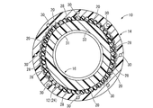
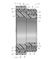
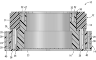
- the front view which shows the wave gear apparatus as 1st embodiment of this invention The front view which shows the state which removed the front cover member of the wave gear apparatus shown in FIG. III-III sectional view of FIG. IV-IV sectional drawing of FIG.
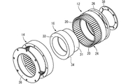
- the disassembled perspective view of the wave gear apparatus shown in FIG. The exploded right view of the wave gear apparatus shown in FIG.
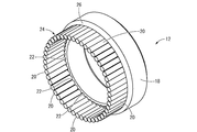
- the perspective view of the flexspline which comprises the wave gear apparatus shown in FIG. The front view of the flexspline shown in FIG.
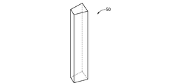
- the right view of the flexspline shown in FIG. The perspective view which shows the pin member which comprises the flexspline of the wave gear apparatus as another one Embodiment of this invention.
- the wave gear device 10 includes a flexspline 12, a circular spline 14, and a wave generator 16.
- the flex spline 12 has a structure in which a plurality of pin members 20 are supported by an annular support member 18 and are arranged in the circumferential direction over the entire circumference. ing.
- the support member 18 is a hard member formed of a synthetic resin such as ABS resin or a metal such as iron, has a substantially annular shape, and opens in an axial end surface in a radially intermediate portion.
- a plurality of bottomed support holes 22 are formed on the circumference.
- the support hole 22 of the present embodiment has a hole cross-sectional area that gradually increases toward the opening side, and the diameter of the support hole 22 is particularly large in the radial direction of the support member 18 as shown in FIG. As a result, the support hole 22 has a substantially circular cross section at the bottom and a substantially oval shape at the opening.
- the pin member 20 is a hard member formed of a synthetic resin or a metal like the support member 18 and has a substantially cylindrical shape with a small diameter.
- the pin member 20 has a substantially circular cross section corresponding to the hole cross-sectional shape of the end portion on the bottom side of the support hole 22.
- the pin member 20 has one end portion in the axial direction inserted into the support hole 22 of the support member 18, and one end portion in the axial direction is detachably supported by the support member 18.
- the pin member 20 extends in a substantially constant circular cross section in the axial direction, with respect to the opening portion of the support hole 22 having a substantially oval cross section whose cross sectional area is larger than the end portion on the bottom side, At least in the major axis direction, they are separated from the inner circumference.
- the pin member 20 can be tilted with respect to the support member 18.
- tilting in the radial direction of the support member 18 is allowed, while in the circumferential direction of the support member 18. Tilt is limited and the plurality of pin members 20 are positioned relative to each other.
- a plurality of (in this embodiment, 50) pin members 20 are supported by one end portion in the axial direction by the support member 18 and arranged side by side in the circumferential direction.
- a cylindrical portion 24 is configured by a portion protruding from the 18 support holes 22. Since this cylindrical part 24 is comprised by the several pin member 20, the unevenness
- the cylindrical portion 24 having external teeth on the outer peripheral surface is constituted by a plurality of pin members 20 arranged in the circumferential direction.
- the external teeth of the present embodiment have a substantially semi-cylindrical tooth surface and are arranged side by side in the circumferential direction, but the external teeth are not limited to a semi-cylindrical shape, depending on the shape of the pin member 20. There may be a polygonal column shape.
- an elastic holding body 26 as a holding means is attached to the cylindrical portion 24.
- the elastic holding body 26 is formed of an elastic material such as rubber or elastomer, has a ring shape, and is externally fitted to the base end portion of the cylindrical portion 24.
- the inner diameter dimension of the elastic holder 26 is slightly smaller than the outer diameter dimension of the neutral cylindrical portion 24 in which the pin member 20 is disposed so as to extend on the central axis of the support hole 22. Since the elastic holding body 26 is externally fitted to the portion 24, a force in the inner circumferential direction is elastically exerted on the cylindrical portion 24.
- a circular spline 14 and a wave generator 16 are assembled to the flexspline 12 having such a structure.
- the circular spline 14 is a hard member made of synthetic resin or metal, has a substantially annular shape, and has an inner tooth with a shape corresponding to the pin member 20 of the flexspline 12 on the inner peripheral surface. 28 is formed.
- the inner teeth 28 are formed two more than the pin members 20 constituting the outer teeth, and 52 inner teeth 28 are formed side by side in the circumferential direction.
- a plurality of screw holes 30 penetrating in the axial direction are formed at equal intervals on the outer peripheral portion of the circular spline 14.
- the inner peripheral surface of the circular spline 14 is inclined with respect to the central axis, and the inner teeth 28 and the tooth grooves thereof are also inclined with respect to the central axis.
- the cylindrical part 24 of the flexspline 12 is inserted in the inner periphery of the circular spline 14. Note that the circular spline 14 is disposed axially away from the support member 18 of the flexspline 12, and relative rotation with respect to the support member 18 is allowed without causing frictional resistance.
- the wave generator 16 has a stepped cylindrical shape whose outer diameter changes in the middle in the axial direction, and the outer diameter of the small diameter portion 31 is substantially the same as or slightly smaller than the inner diameter of the support member 18 of the flexspline 12.
- a plurality of screw holes 32 opened to the end face in the axial direction are distributed on the circumference.
- the large-diameter portion 33 of the wave generator 16 has a cylindrical surface whose inner peripheral surface is a cylindrical surface extending in the axial direction with a substantially constant circular cross section, and a tapered cylindrical surface 34 whose outer peripheral surface is inclined with respect to the central axis.
- the tapered cylindrical surface 34 is inclined in a direction corresponding to the inner peripheral surface of the circular spline 14, and the tapered cylindrical surface 34 and the inner peripheral surface of the circular spline 14 are at least long in a state where the tapered cylindrical surface 34 is arranged to be inserted / extracted later.
- the shaft portions face each other substantially in parallel.
- the large-diameter portion 33 of the wave generator 16 has an outer peripheral surface that is a substantially elliptic cylindrical surface, and the outer diameter dimension in the minor axis direction is substantially the same or slightly smaller than the inner diameter dimension of the neutral cylindrical portion 24.
- the outer diameter dimension in the major axis direction is made larger than the inner diameter dimension of the neutral cylindrical portion 24.
- the wave generator 16 is interpolated into the flex spline 12. That is, the wave generator 16 has a small-diameter portion 31 inserted into the inner periphery of the support member 18 of the flexspline 12 and a large-diameter portion 33 inserted into the inner periphery of the tubular portion 24 of the flexspline 12. 14 and the entire circumference are opposed to each other in the radial direction.
- the circular spline 14 and the wave generator 16 are assembled in an extrapolated state, the front cover member 36 is attached to the circular spline 14 and the rear cover member 38 is attached to the wave generator 16. 12, the circular spline 14 and the wave generator 16 are positioned relative to each other in the axial direction.
- the front lid member 36 has a substantially annular plate shape, and a screw (not shown) that is inserted into the insertion hole 40 that is formed through the outer peripheral portion is screwed into the screw hole 30 of the circular spline 14. It is fixed to the circular spline 14.
- the inner peripheral portion of the front lid member 36 fixed to the circular spline 14 protrudes to the inner periphery from the circular spline 14, the axial end surface of the pin member 20 of the flexspline 12, and the large diameter of the wave generator 16.
- the portions 33 are overlapped in the axial direction with respect to the axial end surface.
- the rear lid member 38 has a substantially annular plate shape with a smaller diameter than the front lid member 36, and a screw (not shown) inserted into the insertion hole 42 penetrating in the thickness direction is a small diameter portion of the wave generator 16. It is fixed to the wave generator 16 by being screwed into the screw hole 32 of 31. The outer end of the rear lid member 38 fixed to the wave generator 16 is overlapped with the support member 18 of the flexspline 12 in the axial direction.
- the flex spline 12, the circular spline 14, and the wave generator 16 are positioned relative to each other in the axial direction in the mounted state of the front lid member 36 and the rear lid member 38, and constitute the wave gear device 10 in the present embodiment. Yes.
- the protruding front end surface of the pin member 20 is covered with the front lid member 36 in a state where the flex spline 12 and the circular spline 14 are positioned in the axial direction, the pin member 20 is prevented from falling off from the support hole 22.
- the pin member 20 is supported by the support member 18.
- the pin member 20 constituting the cylindrical portion 24 of the flex spline 12 is urged toward the inner periphery from the neutral position by the elastic holding body 26, so that the outer peripheral surface of the large-diameter portion 33 of the wave generator 16 is applied. It is elastically held in the pressed state and is arranged along the outer peripheral surface of the wave generator 16. In this embodiment, all the pin members 20 are held in contact with the outer peripheral surface of the wave generator 16, but the pin members 20 located on both sides in the long axis direction of the wave generator 16 are on the outer peripheral surface of the wave generator 16. As long as they are in contact, the pin members 20 located on both sides of the wave generator 16 in the short axis direction may be held away from the outer peripheral surface of the wave generator 16.
- the pin member 20 constituting the external teeth is prevented from rolling by being pressed against the outer peripheral surface of the wave generator 16 by the elastic holding body 26, and the pin is operated when the wave gear device 10 is operated.
- the member 20 does not roll.
- the elastic holding body 26 is a component of the flex spline 12, but it is desirable that the elastic generator 26 be externally fitted to the cylindrical portion 24 after the wave generator 16 is inserted into the cylindrical portion 24.
- the spline 12 is completed while attached to the wave generator 16.
- the pin member 20 is tilted inward by the elasticity of the elastic holding body 26 to form a cylindrical shape. This is because the opening of the portion 24 is reduced, making it difficult to insert the wave generator 16 into the cylindrical portion 24.
- 6 to 9 in order to show that the elastic holding body 26 is a component of the flexspline 12, the elastic holding body 26 is attached to the cylindrical portion 24.
- the tilting of the pin member 20 due to the urging force is shown in the illustration.
- the pin member 20 has a cylindrical portion 24 partially on the circumference by the wave generator 16 at a portion where the outer peripheral surface in the major axis direction of the wave generator 16 is pressed (upper and lower both side portions in FIG. 2). It is pushed to the outer periphery.
- the plurality of pin members 20 pressed against the outer circumferential surface of the wave generator 16 in the major axis direction are tilted from the neutral position so as to incline to the outer circumference (upward and downward in FIG. 2) as they go to the protruding tip.
- the cylindrical portion 24 is partially expanded to the outer periphery.
- the pin member 20 is supported by the support member 18 in a manner in which tilting in the radial direction is allowed, and is elastically held in the radial direction by the elastic holding body 26. 20 is tilted to the outer peripheral side against the elasticity of the elastic holding body 26 by the contact of the long axis portion of the wave generator 16.
- the cylindrical portion 24 of the flexspline 12 is formed in the short axis direction (left-right direction in FIG. 2) of the large-diameter portion 33. Is held along the outer peripheral surface of the wave generator 16 without being spread to the outer periphery by the wave generator 16. Thereby, in the short axis direction of the large-diameter portion 33 of the wave generator 16, the pin member 20 is positioned away from the inner teeth 28 of the circular spline 14 toward the inner circumference, and tooth engagement is avoided. .
- the pin member 20 constituting the external teeth of the flex spline 12 and the internal teeth 28 of the circular spline 14 are partially meshed with each other on the circumference.
- the pin member 20 and the internal teeth 28 are The wave generator 16 is meshed on both sides in the long axis direction.
- the pin member 20 constituting the cylindrical portion 24 is supported at one end in the axial direction by the support member 18, and the displacement amount to the outer peripheral side due to the tilting of the pin member 20 is the length of the pin member 20.
- a large ratio can be obtained. Therefore, even when the length of the pin member 20 is relatively short, the pin member 20 and the internal teeth 28 are held apart in the short axis direction of the wave generator 16 and meshed in the long axis direction. It is possible to reduce the size of the wave gear device 10 in the axial direction.
- the wave gear device 10 having such a structure can be operated as follows, for example. That is, the circular spline 14 is fixed to a case or the like (not shown) and supported so as not to rotate, while an input shaft (not shown) is fixed to the wave generator 16 so that the input shaft can be rotated by an electric motor or the like. An output shaft (not shown) is fixed to the spline 12 so that the rotation of the flex spline 12 is output to the outside by the output shaft.
- a rotational driving force is input to the wave generator 16 via the input shaft, and the wave generator 16 is rotated relative to the circular spline 14.
- the direction of the major axis of the large-diameter portion 33 of the wave generator 16 changes in the circumferential direction as the wave generator 16 rotates, so that the pin member 20 of the flex spline 12 that meshes with the inner teeth 28 of the circular spline 14.
- the position changes sequentially in the circumferential direction as the wave generator 16 rotates.
- the pin members 20 of the flexspline 12 constituting the outer teeth and the number of the inner teeth 28 of the circular spline 14 are different from each other, the pin members 20 and the inner teeth 28 are sequentially bited on the circumference.
- the flex spline 12 rotates in the direction opposite to the rotation direction of the wave generator 16 according to the difference and the size of the number of pin members 20 and internal teeth 28.
- the reduction ratio is 50: 2.
- the pin member 20 is inclined with respect to the central axis of the cylindrical portion 24 at the portion where the pin member 20 of the flexspline 12 and the inner tooth 28 of the circular spline 14 mesh, but the inner tooth 28 of the circular spline 14.
- the tooth groove extends in an inclined manner with respect to the central axis of the circular spline 14 along the inclined pin member 20. Therefore, the pin member 20 and the internal teeth 28 are engaged with each other in a wide area in the axial direction, so that the torque (torque capacity) that can be transmitted can be set large.
- the pin member 20 meshes with the inner teeth 28 in a wide area.
- the target power transmission is stably realized.
- the pin member 20 of the present embodiment is pressed against the outer peripheral surface of the wave generator 16 by the elastic holding body 26 and is prevented from rolling, power transmission due to friction at the time of rolling of the pin member 20 is performed. A decrease in efficiency is also avoided.
- the cylindrical portion 24 of the flexspline 12 is constituted by a plurality of pin members 20 arranged in the circumferential direction, and the pin member 20 constituting the external teeth is provided. By being tilted partially on the circumference of the cylindrical portion 24, it meshes with the internal teeth 28 of the circular spline 14.
- the cylindrical part 24 of the flexspline 12 is composed of a plurality of pin members 20 that can be tilted and displaced substantially independently on the circumference, so that the cylindrical part continuous in the circumferential direction.
- the holding means for holding the cylindrical portion 24 in contact with the outer peripheral surface of the wave generator 16 is provided as an elastic holding body 26 that is separate from the cylindrical portion 24, the conventional means is provided.
- the pin member 20 constituting the cylindrical portion 24 employs a material that can realize the dimensional accuracy for realizing the meshing accuracy required for the gear teeth and the durability against scraping, and the like.
- the support member 18 that supports the plurality of pin members 20 side by side has a simple annular structure and can be easily manufactured.
- the pin member 20 according to the present embodiment can be easily attached to the support member 18 by inserting one end portion in the axial direction into the support hole 22 of the support member 18, so that the assembling work is also simple. It is.
- the holding member that holds the pin member 20 in contact with the outer peripheral surface of the wave generator 16 and allows tilting to the outer periphery when pressed by the wave generator 16 is a cylindrical portion.
- the ring-shaped elastic holding body 26 is fitted on the outer periphery 24. Therefore, the elastic holding body 26 can be attached to the cylindrical portion 24 very easily, and the plurality of pin members 20 are elastically biased toward the inner periphery, thereby stabilizing the outer surface of the wave generator 16. Can be pressed.
- the flex spline 12, the circular spline 14, and the wave generator 16 are all made of synthetic resin, making it easy to manufacture each component and simplifying the weight reduction of the wave gear device 10.
- flexsplines that have been difficult to be made into resins because high dimensional accuracy and strength are required in the past can be made of resin by adopting the structure according to the present invention, and further weight reduction is possible.
- the circular spline 14 and the pin member 20 of the flex spline 12 are formed of a resin material having a small surface friction coefficient, the power loss can be reduced by reducing the frictional resistance at the tooth meshing portion.
- the pin member is not limited to a cylindrical shape. Specifically, it may be a shape having a non-circular cross section such as a polygonal column shape as in the pin member 50 shown in FIG. Note that the pin member mounting structure (for example, the support hole 22) in the support member 18 and the shape of the internal teeth 28 of the circular spline 14 are appropriately changed in accordance with the shape of the pin member.
- the number of pin members 20 and the number of internal teeth 28, and the difference between these numbers are the number of lobes of the wave generator 16 (the number of portions that push the cylindrical portion 24 in the large diameter portion 33 outward), It can be changed as appropriate according to the required reduction ratio.
- the pin member 20 may be supported by the support member 18 so as to be able to roll.
- the support member that positions and supports the pin member 20 in the circumferential direction may be attached so as to support the intermediate portion in the axial direction of the pin member. It is not limited to what supports.
- the mounting structure of the pin member 20 and the support member 18 in which the axial end portion of the pin member 20 shown in the embodiment is inserted into the support hole 22 is merely an example, and for example, the pin member 20 is perpendicular to the axis.
- the structure etc. which equip the inner peripheral surface or the outer peripheral surface with a plurality of concave portions fitted together in FIG.
- the specific structure of the elastic holding body is not limited to the ring shape that is externally fitted to the cylindrical portion 24 shown in the embodiment. That is, an elastic holding body may be disposed between the inner peripheral surface of the support hole 22 of the support member 18 and the outer peripheral surface of the pin member 20, for example, by covering the inner peripheral surface of the support hole 22 with a rubber layer. Can be done.
- the elastic holder is not necessarily provided as an independent component.
- the pin member 20 itself is formed of an elastic body so that the pin member 20 also serves as the elastic holder. It may be held by its own elasticity.
- the support member 18 is formed of an elastic body and the support member 18 also serves as an elastic holding body, the pin member 20 is held by the elasticity of the support member 18.
- the wave generator 16 moves to the outer peripheral side depending on the support mode by the support member or the elastic holding body and the pressing mode by the outer peripheral surface of the wave generator 16. Even when the pin member 20 is spread out, the entire pin member 20 may not be inclined with a clear inclination angle. However, it is understood that the pin member 20 tilts when at least the tip of the pin member 20 moves to the outer peripheral side from the initial position. For example, even when the entire pin member 20 moves to the outer peripheral side, it can be grasped as a tilting mode in which the inner end 28 of the circular spline 14 can be engaged with the movement of the tip end of the pin member 20 to the outer peripheral side.
- the holding means for holding the pin member 20 on the outer peripheral surface of the wave generator 16 is not limited to the elastic means of the member.
- a magnetic attraction is provided between the outer peripheral surface of the wave generator 16 and the pin member 20.
- a force may be applied so that the pin member 20 is attracted and held on the outer peripheral surface of the wave generator 16.
- the flex spline 12, the circular spline 14, and the wave generator 16 are all made of resin, but their forming materials are not particularly limited, and are made of metal such as iron or aluminum alloy, for example. It may be.
- the wave generator 16 has, for example, a structure in which an elliptical plate-like cam plate is disposed on the inner periphery of a ball bearing having a flexible inner ring and an outer ring, and the cam plate is fixed to the inner ring of the ball bearing. Can also be employed. By adopting such a structure with ball bearings, a reduction in power transmission efficiency due to friction between the wave generator 16 and the flexspline can be suppressed.
- the number of lobes of the wave generator 16 may be three or more, and generally the difference in the number of teeth between the external teeth 20 and the internal teeth 28 is set to an integral multiple of the number of lobes.
- the circular spline 14 is fixed to be non-rotatable and an output shaft is attached to the flexspline 12 so that the rotation of the flexspline 12 is taken out as an output. May be fixed to be non-rotatable, and an output shaft may be attached to the circular spline 14 so that the rotation of the circular spline 14 is taken out as an output. Further, by fixing the circular spline 14 so as not to rotate and attaching the input shaft to the flex spline 12 and attaching the output shaft to the wave generator 16, the wave gear device 10 can also function as a speed increaser.
Landscapes
- Engineering & Computer Science (AREA)
- General Engineering & Computer Science (AREA)
- Mechanical Engineering (AREA)
- Retarders (AREA)
Abstract
La présente invention concerne une cannelure souple ayant une nouvelle structure, la cannelure souple étant suffisamment déformable en réponse à une entrée radiale depuis un générateur d'ondes, présentant une excellente durabilité, et étant facile à fabriquer et pouvant être obtenue à bas coût ; et un engrenage à onde de déformation utilisant la cannelure souple. Une cannelure souple (12) pour un engrenage à onde de déformation (10) possède une partie cylindrique (24) dotée d'une denture extérieure qui est configurée par une pluralité d'éléments de goupille (20) disposée sur la circonférence et supportée par un élément de support (18). La cannelure souple (12) est dotée d'un moyen de retenue (26) pour retenir les éléments de goupille (20) sur la surface périphérique externe d'un générateur d'ondes (16). La partie cylindrique (24) est en partie évasée vers l'extérieur sur la périphérie de celle-ci par le générateur d'ondes (16), amenant ainsi les éléments de goupille (20) à s'incliner et à engrener la denture intérieure (28) d'une cannelure circulaire (14). Sur une autre partie de la périphérie de la partie cylindrique (24), les éléments de goupille (20) sont retenus au niveau d'une position espacée vers l'intérieur par rapport à la denture intérieure (28) de la cannelure circulaire (14) par le moyen de retenue (26) sans engrener la denture intérieure (28) de la cannelure circulaire (14).
Applications Claiming Priority (2)
| Application Number | Priority Date | Filing Date | Title |
|---|---|---|---|
| JP2015073575A JP2016194315A (ja) | 2015-03-31 | 2015-03-31 | 波動歯車装置用のフレクスプラインとそれを用いた波動歯車装置 |
| JP2015-073575 | 2015-03-31 |
Publications (1)
| Publication Number | Publication Date |
|---|---|
| WO2016158201A1 true WO2016158201A1 (fr) | 2016-10-06 |
Family
ID=57007025
Family Applications (1)
| Application Number | Title | Priority Date | Filing Date |
|---|---|---|---|
| PCT/JP2016/056739 Ceased WO2016158201A1 (fr) | 2015-03-31 | 2016-03-04 | Cannelure souple pour engrenage à onde de déformation et engrenage à onde de déformation utilisant celle-ci |
Country Status (2)
| Country | Link |
|---|---|
| JP (1) | JP2016194315A (fr) |
| WO (1) | WO2016158201A1 (fr) |
Cited By (2)
| Publication number | Priority date | Publication date | Assignee | Title |
|---|---|---|---|---|
| US20180291995A1 (en) * | 2017-04-05 | 2018-10-11 | Nabtesco Corporation | Speed reducing device |
| CN111406164A (zh) * | 2018-11-29 | 2020-07-10 | 日本电产新宝株式会社 | 波动齿轮装置 |
Families Citing this family (2)
| Publication number | Priority date | Publication date | Assignee | Title |
|---|---|---|---|---|
| JP7145601B2 (ja) * | 2017-10-23 | 2022-10-03 | 住友重機械工業株式会社 | 撓み噛み合い式歯車装置 |
| CN113631841B (zh) * | 2020-03-06 | 2024-01-26 | C&M机器人有限公司 | 摩擦波动减速器 |
Citations (3)
| Publication number | Priority date | Publication date | Assignee | Title |
|---|---|---|---|---|
| JPH0666350A (ja) * | 1992-05-14 | 1994-03-08 | Takeda Haguruma Kogyo Kk | 減速装置 |
| JP2004513306A (ja) * | 2000-10-24 | 2004-04-30 | エクスラー アクチエンゲゼルシャフト | ポット状の出力リングを支持リング内に備えた波動伝動装置 |
| JP2007205397A (ja) * | 2006-01-31 | 2007-08-16 | Jtekt Corp | 波動歯車装置及び伝達比可変装置 |
-
2015
- 2015-03-31 JP JP2015073575A patent/JP2016194315A/ja active Pending
-
2016
- 2016-03-04 WO PCT/JP2016/056739 patent/WO2016158201A1/fr not_active Ceased
Patent Citations (3)
| Publication number | Priority date | Publication date | Assignee | Title |
|---|---|---|---|---|
| JPH0666350A (ja) * | 1992-05-14 | 1994-03-08 | Takeda Haguruma Kogyo Kk | 減速装置 |
| JP2004513306A (ja) * | 2000-10-24 | 2004-04-30 | エクスラー アクチエンゲゼルシャフト | ポット状の出力リングを支持リング内に備えた波動伝動装置 |
| JP2007205397A (ja) * | 2006-01-31 | 2007-08-16 | Jtekt Corp | 波動歯車装置及び伝達比可変装置 |
Cited By (3)
| Publication number | Priority date | Publication date | Assignee | Title |
|---|---|---|---|---|
| US20180291995A1 (en) * | 2017-04-05 | 2018-10-11 | Nabtesco Corporation | Speed reducing device |
| US10724604B2 (en) * | 2017-04-05 | 2020-07-28 | Nabtesco Corporation | Speed reducing device |
| CN111406164A (zh) * | 2018-11-29 | 2020-07-10 | 日本电产新宝株式会社 | 波动齿轮装置 |
Also Published As
| Publication number | Publication date |
|---|---|
| JP2016194315A (ja) | 2016-11-17 |
Similar Documents
| Publication | Publication Date | Title |
|---|---|---|
| JP5338447B2 (ja) | 電動アクチュエータ | |
| KR101703498B1 (ko) | 파동 기어식 직동 기구 | |
| KR101855712B1 (ko) | 백래시 방지 싸이클로이드 감속기 | |
| JP6366650B2 (ja) | 平面状湾曲部材およびそれらを用いたアクチュエータ | |
| US20170059026A1 (en) | Harmonic drive apparatus | |
| US20180142740A1 (en) | Clutch | |
| JP2007100730A5 (fr) | ||
| JP2016194315A (ja) | 波動歯車装置用のフレクスプラインとそれを用いた波動歯車装置 | |
| KR101992998B1 (ko) | 하모닉 드라이브 | |
| JP3186812U (ja) | 変速伝動ベアリング | |
| JP2022536416A (ja) | 円形波動ドライブ | |
| US20150285355A1 (en) | Hollow Drive Gear Reduction Mechanism | |
| KR101901278B1 (ko) | 백래시 방지 싸이클로이드 감속기 | |
| CN104105905A (zh) | 剪式齿轮 | |
| WO2017169060A1 (fr) | Cannelure flexible pour dispositif d'engrenage à onde de déformation, et dispositif d'engrenage à onde de déformation l'utilisant | |
| KR102418835B1 (ko) | 파동 기어 장치 | |
| CN110475988B (zh) | 复合行星摩擦驱动装置 | |
| JP2019044936A (ja) | 変速機 | |
| JP2007205397A (ja) | 波動歯車装置及び伝達比可変装置 | |
| JP2020197264A (ja) | 波動歯車装置 | |
| US7766781B2 (en) | Differential | |
| JP4882906B2 (ja) | 電動式パワーステアリング装置 | |
| JP7000848B2 (ja) | 直動アクチュエータ | |
| JP2011093485A (ja) | 電動式パワーステアリング装置 | |
| JP5256958B2 (ja) | 電動式パワーステアリング装置 |
Legal Events
| Date | Code | Title | Description |
|---|---|---|---|
| 121 | Ep: the epo has been informed by wipo that ep was designated in this application |
Ref document number: 16772085 Country of ref document: EP Kind code of ref document: A1 |
|
| NENP | Non-entry into the national phase |
Ref country code: DE |
|
| 122 | Ep: pct application non-entry in european phase |
Ref document number: 16772085 Country of ref document: EP Kind code of ref document: A1 |