WO2016158381A1 - Palier à gaz à pression statique - Google Patents
Palier à gaz à pression statique Download PDFInfo
- Publication number
- WO2016158381A1 WO2016158381A1 PCT/JP2016/058132 JP2016058132W WO2016158381A1 WO 2016158381 A1 WO2016158381 A1 WO 2016158381A1 JP 2016058132 W JP2016058132 W JP 2016058132W WO 2016158381 A1 WO2016158381 A1 WO 2016158381A1
- Authority
- WO
- WIPO (PCT)
- Prior art keywords
- plate
- slider
- gas bearing
- static pressure
- pressure gas
- Prior art date
- Legal status (The legal status is an assumption and is not a legal conclusion. Google has not performed a legal analysis and makes no representation as to the accuracy of the status listed.)
- Ceased
Links
Images



Classifications
-
- F—MECHANICAL ENGINEERING; LIGHTING; HEATING; WEAPONS; BLASTING
- F16—ENGINEERING ELEMENTS AND UNITS; GENERAL MEASURES FOR PRODUCING AND MAINTAINING EFFECTIVE FUNCTIONING OF MACHINES OR INSTALLATIONS; THERMAL INSULATION IN GENERAL
- F16C—SHAFTS; FLEXIBLE SHAFTS; ELEMENTS OR CRANKSHAFT MECHANISMS; ROTARY BODIES OTHER THAN GEARING ELEMENTS; BEARINGS
- F16C32/00—Bearings not otherwise provided for
- F16C32/06—Bearings not otherwise provided for with moving member supported by a fluid cushion formed, at least to a large extent, otherwise than by movement of the shaft, e.g. hydrostatic air-cushion bearings
- F16C32/0603—Bearings not otherwise provided for with moving member supported by a fluid cushion formed, at least to a large extent, otherwise than by movement of the shaft, e.g. hydrostatic air-cushion bearings supported by a gas cushion, e.g. an air cushion
- F16C32/0614—Bearings not otherwise provided for with moving member supported by a fluid cushion formed, at least to a large extent, otherwise than by movement of the shaft, e.g. hydrostatic air-cushion bearings supported by a gas cushion, e.g. an air cushion the gas being supplied under pressure, e.g. aerostatic bearings
-
- F—MECHANICAL ENGINEERING; LIGHTING; HEATING; WEAPONS; BLASTING
- F16—ENGINEERING ELEMENTS AND UNITS; GENERAL MEASURES FOR PRODUCING AND MAINTAINING EFFECTIVE FUNCTIONING OF MACHINES OR INSTALLATIONS; THERMAL INSULATION IN GENERAL
- F16C—SHAFTS; FLEXIBLE SHAFTS; ELEMENTS OR CRANKSHAFT MECHANISMS; ROTARY BODIES OTHER THAN GEARING ELEMENTS; BEARINGS
- F16C29/00—Bearings for parts moving only linearly
- F16C29/005—Guide rails or tracks for a linear bearing, i.e. adapted for movement of a carriage or bearing body there along
-
- F—MECHANICAL ENGINEERING; LIGHTING; HEATING; WEAPONS; BLASTING
- F16—ENGINEERING ELEMENTS AND UNITS; GENERAL MEASURES FOR PRODUCING AND MAINTAINING EFFECTIVE FUNCTIONING OF MACHINES OR INSTALLATIONS; THERMAL INSULATION IN GENERAL
- F16C—SHAFTS; FLEXIBLE SHAFTS; ELEMENTS OR CRANKSHAFT MECHANISMS; ROTARY BODIES OTHER THAN GEARING ELEMENTS; BEARINGS
- F16C29/00—Bearings for parts moving only linearly
- F16C29/02—Sliding-contact bearings
-
- F—MECHANICAL ENGINEERING; LIGHTING; HEATING; WEAPONS; BLASTING
- F16—ENGINEERING ELEMENTS AND UNITS; GENERAL MEASURES FOR PRODUCING AND MAINTAINING EFFECTIVE FUNCTIONING OF MACHINES OR INSTALLATIONS; THERMAL INSULATION IN GENERAL
- F16C—SHAFTS; FLEXIBLE SHAFTS; ELEMENTS OR CRANKSHAFT MECHANISMS; ROTARY BODIES OTHER THAN GEARING ELEMENTS; BEARINGS
- F16C29/00—Bearings for parts moving only linearly
- F16C29/02—Sliding-contact bearings
- F16C29/025—Hydrostatic or aerostatic
-
- F—MECHANICAL ENGINEERING; LIGHTING; HEATING; WEAPONS; BLASTING
- F16—ENGINEERING ELEMENTS AND UNITS; GENERAL MEASURES FOR PRODUCING AND MAINTAINING EFFECTIVE FUNCTIONING OF MACHINES OR INSTALLATIONS; THERMAL INSULATION IN GENERAL
- F16C—SHAFTS; FLEXIBLE SHAFTS; ELEMENTS OR CRANKSHAFT MECHANISMS; ROTARY BODIES OTHER THAN GEARING ELEMENTS; BEARINGS
- F16C32/00—Bearings not otherwise provided for
- F16C32/06—Bearings not otherwise provided for with moving member supported by a fluid cushion formed, at least to a large extent, otherwise than by movement of the shaft, e.g. hydrostatic air-cushion bearings
-
- F—MECHANICAL ENGINEERING; LIGHTING; HEATING; WEAPONS; BLASTING
- F16—ENGINEERING ELEMENTS AND UNITS; GENERAL MEASURES FOR PRODUCING AND MAINTAINING EFFECTIVE FUNCTIONING OF MACHINES OR INSTALLATIONS; THERMAL INSULATION IN GENERAL
- F16C—SHAFTS; FLEXIBLE SHAFTS; ELEMENTS OR CRANKSHAFT MECHANISMS; ROTARY BODIES OTHER THAN GEARING ELEMENTS; BEARINGS
- F16C32/00—Bearings not otherwise provided for
- F16C32/06—Bearings not otherwise provided for with moving member supported by a fluid cushion formed, at least to a large extent, otherwise than by movement of the shaft, e.g. hydrostatic air-cushion bearings
- F16C32/0662—Details of hydrostatic bearings independent of fluid supply or direction of load
- F16C32/0666—Details of hydrostatic bearings independent of fluid supply or direction of load of bearing pads
-
- F—MECHANICAL ENGINEERING; LIGHTING; HEATING; WEAPONS; BLASTING
- F16—ENGINEERING ELEMENTS AND UNITS; GENERAL MEASURES FOR PRODUCING AND MAINTAINING EFFECTIVE FUNCTIONING OF MACHINES OR INSTALLATIONS; THERMAL INSULATION IN GENERAL
- F16C—SHAFTS; FLEXIBLE SHAFTS; ELEMENTS OR CRANKSHAFT MECHANISMS; ROTARY BODIES OTHER THAN GEARING ELEMENTS; BEARINGS
- F16C33/00—Parts of bearings; Special methods for making bearings or parts thereof
- F16C33/72—Sealings
- F16C33/74—Sealings of sliding-contact bearings
-
- F—MECHANICAL ENGINEERING; LIGHTING; HEATING; WEAPONS; BLASTING
- F16—ENGINEERING ELEMENTS AND UNITS; GENERAL MEASURES FOR PRODUCING AND MAINTAINING EFFECTIVE FUNCTIONING OF MACHINES OR INSTALLATIONS; THERMAL INSULATION IN GENERAL
- F16J—PISTONS; CYLINDERS; SEALINGS
- F16J15/00—Sealings
- F16J15/02—Sealings between relatively-stationary surfaces
- F16J15/021—Sealings between relatively-stationary surfaces with elastic packing
- F16J15/022—Sealings between relatively-stationary surfaces with elastic packing characterised by structure or material
-
- F—MECHANICAL ENGINEERING; LIGHTING; HEATING; WEAPONS; BLASTING
- F16—ENGINEERING ELEMENTS AND UNITS; GENERAL MEASURES FOR PRODUCING AND MAINTAINING EFFECTIVE FUNCTIONING OF MACHINES OR INSTALLATIONS; THERMAL INSULATION IN GENERAL
- F16J—PISTONS; CYLINDERS; SEALINGS
- F16J15/00—Sealings
- F16J15/02—Sealings between relatively-stationary surfaces
- F16J15/06—Sealings between relatively-stationary surfaces with solid packing compressed between sealing surfaces
- F16J15/08—Sealings between relatively-stationary surfaces with solid packing compressed between sealing surfaces with exclusively metal packing
- F16J15/0806—Sealings between relatively-stationary surfaces with solid packing compressed between sealing surfaces with exclusively metal packing characterised by material or surface treatment
-
- F—MECHANICAL ENGINEERING; LIGHTING; HEATING; WEAPONS; BLASTING
- F16—ENGINEERING ELEMENTS AND UNITS; GENERAL MEASURES FOR PRODUCING AND MAINTAINING EFFECTIVE FUNCTIONING OF MACHINES OR INSTALLATIONS; THERMAL INSULATION IN GENERAL
- F16J—PISTONS; CYLINDERS; SEALINGS
- F16J15/00—Sealings
- F16J15/02—Sealings between relatively-stationary surfaces
- F16J15/06—Sealings between relatively-stationary surfaces with solid packing compressed between sealing surfaces
- F16J15/08—Sealings between relatively-stationary surfaces with solid packing compressed between sealing surfaces with exclusively metal packing
- F16J15/0818—Flat gaskets
-
- F—MECHANICAL ENGINEERING; LIGHTING; HEATING; WEAPONS; BLASTING
- F16—ENGINEERING ELEMENTS AND UNITS; GENERAL MEASURES FOR PRODUCING AND MAINTAINING EFFECTIVE FUNCTIONING OF MACHINES OR INSTALLATIONS; THERMAL INSULATION IN GENERAL
- F16C—SHAFTS; FLEXIBLE SHAFTS; ELEMENTS OR CRANKSHAFT MECHANISMS; ROTARY BODIES OTHER THAN GEARING ELEMENTS; BEARINGS
- F16C2202/00—Solid materials defined by their properties
- F16C2202/02—Mechanical properties
- F16C2202/08—Resilience, elasticity, super-elasticity
-
- F—MECHANICAL ENGINEERING; LIGHTING; HEATING; WEAPONS; BLASTING
- F16—ENGINEERING ELEMENTS AND UNITS; GENERAL MEASURES FOR PRODUCING AND MAINTAINING EFFECTIVE FUNCTIONING OF MACHINES OR INSTALLATIONS; THERMAL INSULATION IN GENERAL
- F16C—SHAFTS; FLEXIBLE SHAFTS; ELEMENTS OR CRANKSHAFT MECHANISMS; ROTARY BODIES OTHER THAN GEARING ELEMENTS; BEARINGS
- F16C2206/00—Materials with ceramics, cermets, hard carbon or similar non-metallic hard materials as main constituents
-
- F—MECHANICAL ENGINEERING; LIGHTING; HEATING; WEAPONS; BLASTING
- F16—ENGINEERING ELEMENTS AND UNITS; GENERAL MEASURES FOR PRODUCING AND MAINTAINING EFFECTIVE FUNCTIONING OF MACHINES OR INSTALLATIONS; THERMAL INSULATION IN GENERAL
- F16C—SHAFTS; FLEXIBLE SHAFTS; ELEMENTS OR CRANKSHAFT MECHANISMS; ROTARY BODIES OTHER THAN GEARING ELEMENTS; BEARINGS
- F16C2223/00—Surface treatments; Hardening; Coating
- F16C2223/30—Coating surfaces
- F16C2223/60—Coating surfaces by vapour deposition, e.g. PVD, CVD
-
- F—MECHANICAL ENGINEERING; LIGHTING; HEATING; WEAPONS; BLASTING
- F16—ENGINEERING ELEMENTS AND UNITS; GENERAL MEASURES FOR PRODUCING AND MAINTAINING EFFECTIVE FUNCTIONING OF MACHINES OR INSTALLATIONS; THERMAL INSULATION IN GENERAL
- F16C—SHAFTS; FLEXIBLE SHAFTS; ELEMENTS OR CRANKSHAFT MECHANISMS; ROTARY BODIES OTHER THAN GEARING ELEMENTS; BEARINGS
- F16C2300/00—Application independent of particular apparatuses
- F16C2300/40—Application independent of particular apparatuses related to environment, i.e. operating conditions
- F16C2300/62—Application independent of particular apparatuses related to environment, i.e. operating conditions low pressure, e.g. elements operating under vacuum conditions
Definitions
- the present invention relates to a static pressure gas bearing used in a vacuum environment.
- a static pressure gas bearing is known as such a bearing.
- the static pressure gas bearing is configured such that the slider can move smoothly with respect to the guide shaft by ejecting compressed gas from an air pad provided in the slider.
- the static pressure gas bearing has an advantage that there is no generation of fine dust from the lubricating oil and the sliding surface unlike the rolling bearing and the linear guide.
- Patent Document 1 describes that a solvent having a high airtightness is applied to a gap between movable plates composed of a top plate, a bottom plate, and side plates.
- Patent Document 2 describes that an adhesive is sealed as a sealing agent on a fastening surface of a moving body formed by fastening a top plate, a bottom plate, and a side plate to each other with bolts and cured.
- Patent Document 1 when a solvent is applied to the gap between the plates, there is a problem that the sealing effect is lowered due to aging of the solvent, or the deteriorated solvent is detached from the gap and becomes fine dust. Further, as in Patent Document 2, when the plates are bonded together with an adhesive, there is a problem that it becomes difficult to disassemble the moving body for maintenance and adjustment.
- the present invention has been made in view of such circumstances, and an object of the present invention is to reduce or prevent gas leakage from a joint surface of a plate-like member constituting a slider in a static pressure gas bearing used in a vacuum environment. It is to provide technology to do.
- An aspect of the present invention is a static pressure gas bearing including a guide shaft and a cylindrical slider that can move in the axial direction while accommodating the guide shaft.
- the slider is configured by fastening a plurality of plate-like members, and a film made of a soft material having a smaller elastic modulus than that of the plate-like members is interposed on a joint surface between the plate-like members.
- a softer film than the plate-like members is crushed to fill the gaps in the joint surfaces, so that only the fastening is performed without using an adhesive or a solvent. Gas leakage can be reduced or prevented.
- the plate member may be made of ceramics and the film may be formed by aluminum vapor deposition. According to this, it is possible to easily form a film on the joint surface of the plate-like member.
- the present invention in a static pressure gas bearing used in a vacuum environment, it is possible to reduce or prevent gas leakage from the joint surface of the plate-like member constituting the slider.
- FIG. 1 It is a schematic perspective view of the static pressure gas bearing which concerns on one Embodiment of this invention. It is a perspective view of the slider which comprises a static pressure gas bearing. It is a figure explaining the principle of operation of a static pressure gas bearing. It is a table
- FIG. 1 is a schematic perspective view of a static pressure gas bearing 10 according to an embodiment of the present invention.
- the static pressure gas bearing 10 includes a guide shaft 12 extending in one direction and a cylindrical slider 20 that can move in the axial direction along the guide shaft 12 while accommodating the guide shaft 12 therein. Both ends of the guide shaft 12 are supported by a leg base 14.
- the slider 20 is attached to the guide shaft 12 so as to have a slight gap. As will be described later in detail, the slider 20 can move smoothly along the guide shaft 12 by ejecting compressed gas (for example, air) from an air pad provided inside the slider 20.
- compressed gas for example, air
- the static pressure gas bearing 10 is used for driving a movable stage in an apparatus operating in a vacuum chamber such as an electron beam exposure apparatus.
- a vacuum chamber such as an electron beam exposure apparatus.
- the static pressure gas bearing is a magnetic material, it may affect the trajectory of the electron beam. Made of ceramics.
- the static pressure gas bearing 10 is particularly suitable for use in a vacuum environment because there is no generation of solvent such as lubricating oil or fine dust from the sliding surface as compared with a slider using, for example, a rolling bearing or a linear guide. ing.
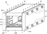
- FIG. 2 is a perspective view of the slider 20.
- the slider 20 has a cylindrical shape with a rectangular cross section, and is configured by combining four plate-like members 20A to 20D.
- the plate-like members are fastened by a plurality of bolts 22.
- fine adjustment is required for fastening the plate-like members so that a desired gap is formed between the guide shaft 12 and the inner surface of the slider 20.
- a plurality of air pads 30 are formed on the inner side of each of the plate-like members 20A to 20D, that is, on the surface with respect to the guide shaft 12.
- the air pad 30 levitates the slider 20 from the guide shaft 12 by ejecting a high-pressure gas supplied from an air supply system (not shown) and forming a high-pressure gas layer in a minute gap between the air pad 30 and the guide shaft 12. .
- Exhaust grooves 34 and 36 for differential exhaust are formed at both ends of each plate-like member 20A to 20D so as to surround the plurality of air pads 30.
- the exhaust grooves 34 and 36 are each connected to an exhaust pump (not shown) and exhaust the gas in the internal space of the slider 20 to the outside. This prevents the compressed gas from leaking from the gap between the guide shaft 12 and the slider 20, thereby preventing the vacuum degree in the vacuum chamber from being lowered. Since the structure of such a slider is well known, further detailed description is omitted in this specification.
- FIG. 3 is a diagram for explaining the operating principle of a gas pressure actuator incorporating the static pressure gas bearing 10.
- a partition wall 42 that divides an air servo chamber 40 formed inside the slider 20 into two servo chambers 40 ⁇ / b> A and 40 ⁇ / b> B in the axial direction is fixed to the guide shaft 12.
- the two servo chambers 40A and 40B are connected to air supply systems 17A and 17B for allowing compressed gas to enter and exit the servo chambers, respectively.
- the air supply systems 17A and 17B include servo valves 16A and 16B and compressed gas supply sources 18A and 18B, respectively.
- the slider 20 When the compressed air is supplied to the air pad 30, the slider 20 slightly floats with respect to the guide shaft 12.
- the partition wall 42 acts as a piston, and the slider 20 moves to the left in the drawing.
- the slider 20 can be moved to an arbitrary position with respect to the guide shaft 12 by controlling the opening degree of the servo valves 16A and 16B. Since the operation principle of such a gas pressure actuator is well known, further detailed description is omitted in this specification.
- ceramics which is the material of each plate-like member constituting the slider 20, has high hardness, and the joining surface of the plate-like member cannot be made completely smooth due to problems of processing accuracy and processing cost. Therefore, gas leakage occurs from the inside of the slider 20 toward the outside, as indicated by an arrow in FIG. If the amount of leakage of this gas is large, the degree of vacuum in the vacuum chamber is lowered, and a predetermined degree of vacuum cannot be ensured.
- a film 24 made of a soft material having a smaller elastic modulus than the material of the plate member is interposed on the joint surface of the plate members 20A to 20D constituting the slider 20. If it carries out like this, when the plate-shaped members are fastened with the volt
- the film 24 is preferably formed by, for example, aluminum vapor deposition. By using vapor deposition, it is possible to easily form a film on the bonding surface.
- the material of the film is not limited to aluminum as long as it is a soft material having a smaller elastic modulus than the material of the slider (ceramics in this embodiment) and can form a uniform film on the joint surface.
- a film may be formed on the joining surface of the plate member by titanium vapor deposition or galvanization, or an aluminum thin film, a resin sheet, or the like may be interposed on the joining surface of the plate member.
- the specimen A is a slider assembled only by bolt fastening.
- Specimen B is a slider that has a surface roughness of the joining surface of the plate-like member smaller than that of specimen A and is assembled only by bolt fastening.
- the specimen C is a slider that has the same surface roughness as that of the specimen B on the joining surface of the plate-like member, and is assembled by bolt fastening after an aluminum vapor deposition film is formed on the joining surface.
- FIG. 4 is a graph showing the test results.
- the horizontal axis of the graph represents the air pressure in the internal space of the slider, and the vertical axis of the graph represents the amount of air leak from the joint surface of the plate-like member of the slider.
- the amount of leakage from the joining surface can be greatly reduced as compared with specimens A and B that are only bolted. confirmed.
- a plate-like material is interposed between the plate-like members constituting the slider by interposing a film made of a soft material having a smaller elastic modulus than that of the plate-like member. Since the softer film than the plate-like member is crushed when the members are fastened, the gap between the joint surfaces is filled, so that the leakage of gas from the joint surfaces can be reduced only by fastening without using an adhesive or a solvent. Can be prevented.
- the slider can be disassembled and reassembled for maintenance and adjustment even after the slider has been assembled. Further, by not using a solvent, problems such as a decrease in the sealing effect due to aging of the solvent and generation of fine dust can be avoided.
- the static pressure gas bearing is made of a non-magnetic material, particularly ceramics, but the present invention can also be applied to a static pressure gas bearing made of a magnetic material. .
- the guide shaft and the slider of the static pressure gas bearing have a rectangular cross-sectional shape.
- the present invention relates to a static pressure gas bearing including a guide shaft and a slider having an arbitrary cross-sectional shape. Can also be applied.
- the gas pressure actuator in which the static pressure gas bearing is incorporated has been described.
- the present invention can be applied to any static pressure gas bearing regardless of the presence or absence of the actuator.
- the present invention in a static pressure gas bearing used in a vacuum environment, it is possible to reduce or prevent gas leakage from the joint surface of the plate-like member constituting the slider.
Landscapes
- Engineering & Computer Science (AREA)
- General Engineering & Computer Science (AREA)
- Mechanical Engineering (AREA)
- Magnetic Bearings And Hydrostatic Bearings (AREA)
- Bearings For Parts Moving Linearly (AREA)
Abstract
La présente invention concerne un palier à gaz à pression statique à utiliser dans un environnement sous vide, qui est doté d'un arbre de guidage et d'une glissière tubulaire 20 qui loge l'arbre de guidage tout en étant capable de se déplacer dans la direction axiale. La glissière 20 est configurée par fixation de plusieurs éléments en forme de plaque 20A-20D. Un film 24, obtenu à partir d'un matériau mou ayant un module élastique inférieur à celui des éléments en forme de plaque, est interposé entre les surfaces de liaison des éléments en forme de plaque.
Priority Applications (4)
| Application Number | Priority Date | Filing Date | Title |
|---|---|---|---|
| EP16772264.4A EP3279489B1 (fr) | 2015-03-31 | 2016-03-15 | Palier à gaz à pression statique |
| CN201680016002.7A CN107429742A (zh) | 2015-03-31 | 2016-03-15 | 静压气体轴承 |
| KR1020177025388A KR102423262B1 (ko) | 2015-03-31 | 2016-03-15 | 정압기체베어링 |
| US15/714,601 US20180023624A1 (en) | 2015-03-31 | 2017-09-25 | Static pressure gas bearing |
Applications Claiming Priority (2)
| Application Number | Priority Date | Filing Date | Title |
|---|---|---|---|
| JP2015072097A JP6742074B2 (ja) | 2015-03-31 | 2015-03-31 | 静圧気体軸受 |
| JP2015-072097 | 2015-03-31 |
Related Child Applications (1)
| Application Number | Title | Priority Date | Filing Date |
|---|---|---|---|
| US15/714,601 Continuation US20180023624A1 (en) | 2015-03-31 | 2017-09-25 | Static pressure gas bearing |
Publications (1)
| Publication Number | Publication Date |
|---|---|
| WO2016158381A1 true WO2016158381A1 (fr) | 2016-10-06 |
Family
ID=57007112
Family Applications (1)
| Application Number | Title | Priority Date | Filing Date |
|---|---|---|---|
| PCT/JP2016/058132 Ceased WO2016158381A1 (fr) | 2015-03-31 | 2016-03-15 | Palier à gaz à pression statique |
Country Status (7)
| Country | Link |
|---|---|
| US (1) | US20180023624A1 (fr) |
| EP (1) | EP3279489B1 (fr) |
| JP (1) | JP6742074B2 (fr) |
| KR (1) | KR102423262B1 (fr) |
| CN (1) | CN107429742A (fr) |
| TW (1) | TWI589792B (fr) |
| WO (1) | WO2016158381A1 (fr) |
Families Citing this family (3)
| Publication number | Priority date | Publication date | Assignee | Title |
|---|---|---|---|---|
| TWI642858B (zh) * | 2017-09-06 | 2018-12-01 | 友達光電股份有限公司 | 氣浮軸承模組 |
| CN108547870B (zh) * | 2018-05-09 | 2019-03-29 | 哈尔滨工业大学 | 一种带有非等深节流腔的气浮支承导向装置 |
| CN111894978B (zh) * | 2020-07-22 | 2022-04-26 | 南通理工学院 | 平面支承主动磁悬浮装置 |
Citations (3)
| Publication number | Priority date | Publication date | Assignee | Title |
|---|---|---|---|---|
| JPS62180114A (ja) * | 1986-01-31 | 1987-08-07 | Kyocera Corp | 静圧気体直線案内装置 |
| JPH0221328U (fr) * | 1988-07-28 | 1990-02-13 | ||
| JPH03242386A (ja) * | 1990-02-21 | 1991-10-29 | Toshiba Ceramics Co Ltd | セラミック部材と金属部材の接合構造 |
Family Cites Families (7)
| Publication number | Priority date | Publication date | Assignee | Title |
|---|---|---|---|---|
| US3263025A (en) * | 1963-07-30 | 1966-07-26 | Varian Associates | Demountable metal-to-ceramic seal |
| JP3106474B2 (ja) * | 1990-02-21 | 2000-11-06 | 日本精工株式会社 | 静圧気体軸受 |
| JPH09324272A (ja) * | 1996-03-31 | 1997-12-16 | Furontetsuku:Kk | シール装置 |
| JP2002333022A (ja) | 2001-03-09 | 2002-11-22 | Toto Ltd | 静圧気体軸受 |
| JP2004028214A (ja) | 2002-06-26 | 2004-01-29 | Kyocera Corp | 静圧気体軸受 |
| JP4022508B2 (ja) * | 2003-10-20 | 2007-12-19 | トーカロ株式会社 | セラミック溶射の前処理方法およびその溶射皮膜被覆部材 |
| CN203730559U (zh) * | 2014-02-19 | 2014-07-23 | 日本精工株式会社 | 静压气体轴承 |
-
2015
- 2015-03-31 JP JP2015072097A patent/JP6742074B2/ja active Active
-
2016
- 2016-03-15 EP EP16772264.4A patent/EP3279489B1/fr active Active
- 2016-03-15 KR KR1020177025388A patent/KR102423262B1/ko active Active
- 2016-03-15 WO PCT/JP2016/058132 patent/WO2016158381A1/fr not_active Ceased
- 2016-03-15 CN CN201680016002.7A patent/CN107429742A/zh active Pending
- 2016-03-22 TW TW105108828A patent/TWI589792B/zh active
-
2017
- 2017-09-25 US US15/714,601 patent/US20180023624A1/en not_active Abandoned
Patent Citations (3)
| Publication number | Priority date | Publication date | Assignee | Title |
|---|---|---|---|---|
| JPS62180114A (ja) * | 1986-01-31 | 1987-08-07 | Kyocera Corp | 静圧気体直線案内装置 |
| JPH0221328U (fr) * | 1988-07-28 | 1990-02-13 | ||
| JPH03242386A (ja) * | 1990-02-21 | 1991-10-29 | Toshiba Ceramics Co Ltd | セラミック部材と金属部材の接合構造 |
Also Published As
| Publication number | Publication date |
|---|---|
| EP3279489A1 (fr) | 2018-02-07 |
| CN107429742A (zh) | 2017-12-01 |
| EP3279489A4 (fr) | 2018-10-17 |
| TWI589792B (zh) | 2017-07-01 |
| JP6742074B2 (ja) | 2020-08-19 |
| KR102423262B1 (ko) | 2022-07-19 |
| US20180023624A1 (en) | 2018-01-25 |
| EP3279489B1 (fr) | 2019-11-20 |
| KR20170134369A (ko) | 2017-12-06 |
| TW201638485A (zh) | 2016-11-01 |
| JP2016191434A (ja) | 2016-11-10 |
Similar Documents
| Publication | Publication Date | Title |
|---|---|---|
| JP7122423B2 (ja) | アクチュエータ、ステージ装置および露光装置 | |
| JP2011522193A (ja) | 流体サーボ及び用途 | |
| JP6742074B2 (ja) | 静圧気体軸受 | |
| JP2008511138A (ja) | 空気軸受と段差ポンプ溝を備えた移動真空チャンバステージ | |
| JP6967760B2 (ja) | Xyステージ移動機構 | |
| US20020180159A1 (en) | Sealing device and positioning device using the same | |
| JP2002303323A (ja) | 駆動装置 | |
| JP6707964B2 (ja) | 位置決め装置及び回転機構 | |
| JP7528203B2 (ja) | 真空バルブおよび真空ドア | |
| JP6714605B2 (ja) | 真空バルブ | |
| JP4443778B2 (ja) | 流体圧アクチュエータ | |
| JP2002107479A (ja) | ステージ装置 | |
| JP4365706B2 (ja) | Xyステージ | |
| JP4273743B2 (ja) | 位置決め装置 | |
| JPH10281110A (ja) | 非接触ロッドレスシリンダおよびそれを用いたステージ装置 | |
| JPS63120050A (ja) | 駆動機構 | |
| JP2016121707A (ja) | 回転機構、搬送装置、工作機械および半導体製造装置 | |
| JP2003163256A (ja) | 真空対応型ステージ装置 | |
| JP2004028214A (ja) | 静圧気体軸受 | |
| JP2004031978A (ja) | 露光装置 | |
| JP2007071293A (ja) | ガイド装置 |
Legal Events
| Date | Code | Title | Description |
|---|---|---|---|
| 121 | Ep: the epo has been informed by wipo that ep was designated in this application |
Ref document number: 16772264 Country of ref document: EP Kind code of ref document: A1 |
|
| ENP | Entry into the national phase |
Ref document number: 20177025388 Country of ref document: KR Kind code of ref document: A |
|
| REEP | Request for entry into the european phase |
Ref document number: 2016772264 Country of ref document: EP |
|
| NENP | Non-entry into the national phase |
Ref country code: DE |