WO2016158535A1 - Terminal utilisateur, station de base sans fil et procédé de communication sans fil - Google Patents
Terminal utilisateur, station de base sans fil et procédé de communication sans fil Download PDFInfo
- Publication number
- WO2016158535A1 WO2016158535A1 PCT/JP2016/058867 JP2016058867W WO2016158535A1 WO 2016158535 A1 WO2016158535 A1 WO 2016158535A1 JP 2016058867 W JP2016058867 W JP 2016058867W WO 2016158535 A1 WO2016158535 A1 WO 2016158535A1
- Authority
- WO
- WIPO (PCT)
- Prior art keywords
- phr
- user terminal
- information
- unit
- cell group
- Prior art date
- Legal status (The legal status is an assumption and is not a legal conclusion. Google has not performed a legal analysis and makes no representation as to the accuracy of the status listed.)
- Ceased
Links
Images









Classifications
-
- H—ELECTRICITY
- H04—ELECTRIC COMMUNICATION TECHNIQUE
- H04W—WIRELESS COMMUNICATION NETWORKS
- H04W52/00—Power management, e.g. Transmission Power Control [TPC] or power classes
- H04W52/04—Transmission power control [TPC]
- H04W52/30—Transmission power control [TPC] using constraints in the total amount of available transmission power
- H04W52/36—Transmission power control [TPC] using constraints in the total amount of available transmission power with a discrete range or set of values, e.g. step size, ramping or offsets
- H04W52/365—Power headroom reporting
-
- H—ELECTRICITY
- H04—ELECTRIC COMMUNICATION TECHNIQUE
- H04W—WIRELESS COMMUNICATION NETWORKS
- H04W16/00—Network planning, e.g. coverage or traffic planning tools; Network deployment, e.g. resource partitioning or cells structures
- H04W16/02—Resource partitioning among network components, e.g. reuse partitioning
-
- H—ELECTRICITY
- H04—ELECTRIC COMMUNICATION TECHNIQUE
- H04W—WIRELESS COMMUNICATION NETWORKS
- H04W52/00—Power management, e.g. Transmission Power Control [TPC] or power classes
- H04W52/04—Transmission power control [TPC]
- H04W52/06—TPC algorithms
- H04W52/14—Separate analysis of uplink or downlink
- H04W52/146—Uplink power control
-
- H—ELECTRICITY
- H04—ELECTRIC COMMUNICATION TECHNIQUE
- H04W—WIRELESS COMMUNICATION NETWORKS
- H04W52/00—Power management, e.g. Transmission Power Control [TPC] or power classes
- H04W52/04—Transmission power control [TPC]
- H04W52/30—Transmission power control [TPC] using constraints in the total amount of available transmission power
- H04W52/34—TPC management, i.e. sharing limited amount of power among users or channels or data types, e.g. cell loading
-
- H—ELECTRICITY
- H04—ELECTRIC COMMUNICATION TECHNIQUE
- H04W—WIRELESS COMMUNICATION NETWORKS
- H04W72/00—Local resource management
- H04W72/04—Wireless resource allocation
-
- H—ELECTRICITY
- H04—ELECTRIC COMMUNICATION TECHNIQUE
- H04W—WIRELESS COMMUNICATION NETWORKS
- H04W72/00—Local resource management
- H04W72/04—Wireless resource allocation
- H04W72/044—Wireless resource allocation based on the type of the allocated resource
- H04W72/0453—Resources in frequency domain, e.g. a carrier in FDMA
-
- H—ELECTRICITY
- H04—ELECTRIC COMMUNICATION TECHNIQUE
- H04W—WIRELESS COMMUNICATION NETWORKS
- H04W72/00—Local resource management
- H04W72/20—Control channels or signalling for resource management
- H04W72/23—Control channels or signalling for resource management in the downlink direction of a wireless link, i.e. towards a terminal
Definitions
- the present invention relates to a user terminal, a radio base station, and a radio communication method in a next-generation mobile communication system.
- LTE Long Term Evolution
- Non-Patent Document 1 a LTE successor system (also referred to as LTE-A) called LTE Advanced has been studied for the purpose of further broadbanding and speeding up from LTE, and LTE Rel. It is specified as 10-12.
- LTE Rel One of the 10 to 12 broadband technologies is carrier aggregation (CA).
- CA carrier aggregation
- CC component carrier
- LTE Rel LTE Rel. This corresponds to 8 system bands.
- a user terminal transmits information about uplink surplus transmission power (PH: Power Headroom) for each serving cell to a network side device (for example, a radio base station (eNB)). Report).
- the radio base station can dynamically control the uplink transmission power of the user terminal based on the PHR.
- E-UTRA Evolved Universal Terrestrial Radio Access
- E-UTRAN Evolved Universal Terrestrial Radio Access Network
- the number of CCs that can be set per user terminal is limited to a maximum of five.
- the carrier aggregation in which the number of settable CCs is 6 or more may be referred to as, for example, extended CA.
- the number of CCs that can be set in the user terminal is expanded to 6 or more (for example, 32), it becomes difficult to apply the PHR usage method in the existing system (Rel. 10 to 12) as it is.
- CA of 5 CC or less is assumed. Therefore, when CA of 6 CC or more is applied, information regarding PH for each CC may not be notified to the radio base station at an appropriate timing. For this reason, there is a possibility that the radio base station cannot appropriately control the uplink transmission power of the user terminal.
- the present invention has been made in view of such a point, and even when the number of component carriers that can be set in a user terminal is expanded from an existing system, a user terminal and a radio base station that can appropriately perform communication It is another object of the present invention to provide a wireless communication method.
- the user terminal which concerns on 1 aspect of this invention is a user terminal which can communicate using a some component carrier (CC: Component Carrier), Comprising: For each CC which comprises a predetermined cell group among activated CC A generating unit that generates PHR (Power Headroom Report) including information on PH (Power Headroom), and a transmitting unit that transmits the generated PHR.
- CC Component Carrier
- PHR Power Headroom Report
- PH Power Headroom
- communication can be performed appropriately even when the number of component carriers that can be set in the user terminal is expanded from the existing system.
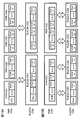
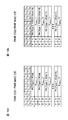
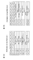
- Rel. 13 is a diagram showing an example of CA. It is a figure which shows an example of PUCCH CG mode. It is a figure which shows the application range of the PHR timer and parameter set in 1st Embodiment. It is a figure which shows an example of PHR MAC CE in 1st Embodiment. It is a figure which shows the applicable range of the PHR timer and parameter in 2nd Embodiment. It is a figure which shows an example of PHR MAC CE in 2nd Embodiment. It is a figure which shows an example of the timing of the PHR trigger in 1st Embodiment. It is a diagram illustrating an example of a PHR to be transmitted at time t 1 and t 2 of FIG.
- FIG. 10B It is a figure which shows an example of the correspondence of PHR CG and PUCCH CG. It is a figure which shows another example of the correspondence of PHR CG and PUCCH CG.
- 3 is a conceptual explanatory diagram of Method 1.
- FIG. It is a figure which shows an example of a structure of PHR MAC CE transmitted in FIG. It is a figure which shows an example of the LCID value used for an uplink shared channel.
- FIG. 3 is a conceptual explanatory diagram of Method 2.
- FIG. It is a figure which shows an example of a structure of PHR MAC CE transmitted in FIG. 10 is a diagram illustrating another example of the method 2.
- FIG. It is a figure which shows an example of schematic structure of the radio
- CA in the conventional LTE successor system (LTE Rel. 10-12), the number of CCs that can be set per user terminal is limited to a maximum of five.
- LTE Rel. 13 and later the restriction on the number of CCs that can be set per user terminal is relaxed, and extended carrier aggregation that sets 6 or more CCs (cells) (also called CA enhancement, enhanced CA, Rel.13 CA, etc.) Is being considered.
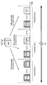
- FIG. 13 is a diagram showing an example of CA. As shown in FIG. In 13 CA, for example, it is assumed that a maximum of 32 CCs are bundled. Since it is inefficient from the viewpoint of communication overhead and controllability to transmit uplink control information (UCI) related to many CCs using only the PUCCH of the PCell, Rel. 13 CA is considering supporting PUCCH cell groups (PUCCH CG).
- PUCCH CG PUCCH cell groups
- the PUCCH cell (PUCCH setting cell) may be a PCell, or may be a SCell (PUCCH SCell) configured to be able to transmit PUCCH.
- the PUCCH cell (PUCCH setting cell) may be a PCell, or may be a SCell (PUCCH SCell) configured to be able to transmit PUCCH.
- PUCCH SCell PUCCH SCells
- FIG. 1 four PUCCH CGs each consisting of eight cells are set, and SCell 8 and SCell 24 are set as PUCCH SCells.
- PUCCH CGs are not necessarily set.
- Rel. 13 CA has been studied to support a mode in which multiple PUCCH cells are set (Multiple PUCCH CGs) and a mode in which PUCCH is transmitted only by a single cell (PCell) (Single PUCCH CG).
- FIG. 2 is a diagram illustrating an example of the PUCCH CG mode.
- FIG. 2A illustrates an example in which a user terminal transmits an uplink signal to an eNB using a plurality of cells.
- 2B and 2C show an example of the PUCCH CG mode corresponding to the example of FIG. 2A.
- a plurality of PUCCH CGs may be set (FIG. 2B), or a single PUCCH CG may be set (FIG. 2C).
- a user terminal feeds back a PHR (Power Headroom Report) including information on PH (PH information) for each serving cell to a radio base station.
- the PHR is composed of PHR MAC CE (Control Element) included in MAC PDU (Medium Access Control Protocol Data Unit).
- the PHR is transmitted by MAC signaling using PUSCH (Physical Uplink Shared Channel).
- the radio base station can dynamically control the transmission power of the user terminal based on the received PHR.
- Type 1 PH is a PH when only PUSCH is considered
- Type 2 PH is a PH when both PUSCH and PUCCH are considered.
- the PH information may be a PH value or an index associated with the PH value (or level).
- the radio base station transmits PHR setting information related to PHR transmission conditions to the user terminal. For example, RRC signaling is used for the notification.
- the user terminal determines the timing for transmitting the PHR based on the notified PHR setting information. That is, when the PHR transmission condition is satisfied, the PHR is triggered.
- the PHR setting information for example, two timers (periodicPHR-Timer and prohibitPHR-Timer) and a predetermined threshold (dl-PathlossChange) can be used.
- a predetermined threshold dl-PathlossChange
- the PHR setting information may be referred to as a PHR timer and a parameter set.
- the CC capable of transmitting the PUCCH is 1 CC or less, so the PHR configuration when the PUCCH can be transmitted at 2 CC or more is not defined. For this reason, there is a possibility that the radio base station cannot appropriately grasp the PH for a predetermined PUCCH cell.
- the present inventors have established LTE Rel.
- the present invention has been conceived to introduce a new PHR configuration different from the existing system. It came.
- FIG. 3 is a diagram showing an application range of the PHR timer and the parameter set in the first embodiment.
- all PUCCH CGs that is, all CCs
- PHR including PH information of all activated (active) CCs is transmitted.
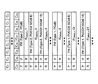
- FIG. 4 is a diagram illustrating an example of the PHR MAC CE according to the first embodiment.
- PH information for a maximum of 32 cells can be included.
- PUCCH cells PCell and PUCCH SCell
- Type 2 PH information is also included.
- the PHR is configured to include Type 2 PH information and Type 1 PH information in ascending order for each cell.
- Type 1 PH information is included for CCs that do not require notification of Type 2 PH information (SCells in which PUCCH is not set).
- PHR including PH information of all CCs can be notified to the radio base station.
- FIG. 5 is a diagram showing the applicable range of the PHR timer and parameters in the second embodiment. As shown in FIG. 5, according to the second embodiment, each PUCCH CG is managed by a separate timer and parameter set. Further, when the PHR is triggered in any CC, the PHR including the PH information of all activated (active) CCs is transmitted.
- FIG. 6 is a diagram illustrating an example of the PHR MAC CE according to the second embodiment.
- PH information for a maximum of 32 cells can be included.
- Type 2 PH information is also included.
- PHR is configured to include Type 2 PH information for the PUCCH cells in ascending order, and then include Type 1 PH information for each cell in ascending order.
- Type 1 PH information is included for CCs that do not require notification of Type 2 PH information (SCells in which PUCCH is not set).
- the examples shown in the first and second embodiments are merely examples, and the arrangement order and number of data are not limited thereto.
- the number of cells including information is not limited to a maximum of 32 cells.
- an LCID (Logical Channel ID) that is not used in the existing system (Rel. 10 to 12) may be used in correspondence with the PHR MAC CE in the first and second embodiments. That is, the MAC PDU may include a predetermined LCID in the MAC header to indicate that the MAC PDU includes the MAC CE corresponding to the PHR in the first or second embodiment.
- PHR in PHR CG unit PHR generated in units of PHR CG (PHR cell group) obtained by grouping CCs based on a predetermined rule is used.
- the PHR corresponding to the extended CA can be used based on the PHR of the existing system, there is an advantage that the mounting cost is low and the migration can be easily performed.
- FIG. 7 is a diagram illustrating an example of the timing of the PHR trigger in the first embodiment.
- the configuration of the extended CA is the same as that in FIG.
- a relatively fine TPC Transmit Power Control
- dl-PathlossChange 1 dB
- the path loss changes by 3 dB.
- the power control of PUCCH CG2 cannot be appropriately performed with the parameter set for PUCCH CG3.
- the parameter set for PUCCH CG2 there is a problem that PHR trigger by PUCCH CG3 increases and unnecessary communication increases.
- the overhead will be described as an example in which a parameter set for PUCCH CG2 is used.
- PHR by a change in the pathloss CG2 is triggered at time t 3
- PHR is triggered by a change in the pathloss CG3.
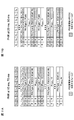
- FIG. 8 is a diagram illustrating an example of PHR transmitted at times t 1 and t 2 in FIG.
- the only CG whose PSD (transmission power density) has changed between these times is PUCCH CG2. Therefore, PH information other than PUCCH CG2 is redundant because the same (or almost the same) content is notified in these PHRs.
- FIG. 9 is a diagram illustrating an example of a relationship between surplus power (PH) and PUCCH / PUSCH transmission power.
- 9A and 9B relate to PCell.
- Each power is as follows.
- (Power used for PUSCH) P CMAX, c 2 -PH1
- (Power used for PUCCH) P CMAX, c 1 -PH2- (P CMAX, c 2 -PH1 ).
- PH1 is Type 1 PH
- PH2 is Type 2 PH.
- FIG. 9C relates to a PUCCH SCell.
- the power used for PUSCH can be obtained by P CMAX, c m-PH1.
- the radio base station cannot specify the power used for the PUCCH of the PUCCH SCell. For this reason, it is not preferable to reduce information about Type 2 PH in order to reduce overhead.
- FIG. 10 is a diagram illustrating an example of the timing of the PHR trigger in the second embodiment.
- FIG. 10A shows the PHR timer and parameter set of each PUCCH CG.
- a PHR timer and a parameter set are independently set in each CG.
- FIG. 10B is a diagram showing an example of the timing of the PHR trigger controlled according to the PHR timer and parameter set of FIG. 10A.
- the timers of both CGs are started at time 0 ms.
- CG1's prohibitPHR-Timer expires and the path loss value fluctuates by dl-PathlossChange or more, so the CG1's PHR is transmitted.
- the CG2 PHR-Timer expires and the path loss value fluctuates by dl-PathlossChange or more, so the CG2 PHR is transmitted.
- the timer of the CG is restarted.
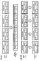
- FIG. 11 is a diagram illustrating an example of the PHR transmitted in FIG. 10B.
- the only CG whose PSD has changed is PUCCH CG1. Therefore, PH information other than PUCCH CG1 has not changed.
- the only CG whose PSD has changed is PUCCH CG2. Therefore, PH information other than PUCCH CG2 has not changed.
- the PHR timer and the parameter set are set for each CG, the PHR includes PH information related to other CGs, resulting in unnecessary overhead.
- the present inventors examined the problems as described above. As a result, the idea was to group CCs based on a predetermined rule. In addition, the idea is to include only PH information of CCs belonging to a predetermined group instead of including PH information of all active CCs in the PHR.
- the inventors have found a third embodiment of the present invention based on these ideas. According to the configuration of the third embodiment of the present invention, the PHR timer and parameters can be set independently for each group, and the PHR overhead can be greatly reduced.
- a PHR cell group (PHR CG) is set in the user terminal.
- the PHR CG is configured to include one or more CCs.
- the user terminal controls PHR transmission timing using different PHR timers and parameters.
- the PHR CG may be configured based on an existing CG or a separately specified CG.
- the PHR CG may be configured based on PUCCH CG, or may be configured based on TAG (Timing Advance Group).
- the user terminal is configured to include only information related to the PH of the active cell belonging to a specific PHR CG in a predetermined MAC CE. Moreover, regarding PUCCH cells (PCell and PUCCH SCell), not only Type 1 PH information but also Type 2 PH information is included.
- PUCCH CG is given as an example of another type of CG, but is not limited to this.
- a user terminal shall be set to carry out 32CC CA, it is not restricted to this.
- FIG. 12 is a diagram illustrating an example of a correspondence relationship between PHR CG and PUCCH CG.
- FIG. 12A shows an example when the user terminal is configured with a single PUCCH CG. In this example, CCs included in the PUCCH CG are allocated to four PHR CGs with 8 CC as a structural unit.
- FIG. 12B shows an example when the user terminal is set with a plurality of PUCCH CGs. In this example, one PUCCH CG is configured to correspond to one PHR CG.
- FIG. 13 is a diagram showing another example of the correspondence between PHR CG and PUCCH CG.
- FIG. 13A shows an example of a configuration in which the number of PHR CGs is greater than the number of PUCCH CGs. In this example, a plurality of PHR CGs are configured to correspond to one PUCCH CG.
- FIG. 13B illustrates an example of a configuration in which the number of PHR CGs is smaller than the number of PUCCH CGs. In this example, one PHR CG is configured to correspond to a plurality of PUCCH CGs.
- the PHR CG can be configured flexibly. Therefore, an appropriate PHR CG can be set according to the combination of CCs to which the same PHR timer and parameters are to be applied.
- the information regarding the configuration of the PHR CG may be notified to the user terminal by, for example, a downlink control signal (DCI), higher layer signaling (for example, RRC signaling), broadcast information, or a combination thereof.
- DCI downlink control signal
- RRC signaling higher layer signaling
- the setting information of the correspondence relationship between the PHR CG and the PUCCH CGC may be notified, or the information of the CC configuring the PHR CG may be notified.
- Information regarding the configuration of the PHR CG may be transmitted together with the PHR setting information or included in the PHR setting information.
- the information regarding the structure of PHR CG may be preset.
- PHR transmission method In the third embodiment, the following two methods will be described as PHR transmission methods.
- the PHR CGn (n is a natural number, for example) PHR is transmitted in one of the activated CCs included in the PHR CGn.
- PHR CGn (n is a natural number, for example) PHR is transmitted in any activated cell regardless of PHR CG.
- the PHR MAC CE related to a predetermined CG can be transmitted in a cell belonging to the predetermined CG. Further, in the method 2, the PHR MAC CE related to a predetermined CG can be transmitted by a CC belonging to the same CG as the predetermined CG and / or a CC belonging to a different CG.
- These PHR MAC CEs can contain more information than conventional PHR MAC CEs (Extended PHR MAC CE, Dual Connectivity PHR MAC CE, etc.).
- FIG. 14 is a conceptual explanatory diagram of Method 1.
- the user terminal is set to perform CA at 32 CC
- PHR CG1 is configured with PCell and SCell 1-15
- PHR CG2 is configured with SCell 16-31.
- PUSCHs are assigned to SCell 15 and SCell 16, and PHR CG1 and PHR 2 are transmitted on these PUSCHs, respectively.
- the PHR CGs 1 and 2 correspond to the PUCCH CGs 1 and 2, respectively, but are not limited to this configuration.
- FIG. 15 is a diagram showing an example of the configuration of the PHR MAC CE transmitted in FIG. In FIG. 14, each PHR CG is composed of 16 CCs. For this reason, as shown in FIG. 15A, the PHR MAC CE of PHR CG1 is configured to include 16 CC PH information included in PHR CG1. Further, as shown in FIG. 15B, the PHR MAC CE of PHR CG2 is configured to include 16 CC PH information included in PHR CG2.
- PHR is transmitted using each CG at 70 ms and 90 ms, since these PHRs include only the PH information of CCs belonging to the respective CGs, redundant information is not transmitted.
- the PHR of Method 1 includes information for indicating that it is a new PHR different from the existing PHR.
- the new PHR may be referred to as PHR CG PHR.
- the MAC PDU in Method 1 includes an LCID that is not used in the existing system (Rel. 10 to 12) in the MAC header.
- FIG. 16 is a diagram illustrating an example of the LCID value used for the uplink shared channel.
- the LCID corresponding to the index “10111” indicates that the MAC PDU including the LCID includes a MAC CE corresponding to the PHR CG PHR.
- the LCID corresponding to the index “10111” is only reserved and has not been used.
- the LCID indicating the PHR CG PHR is not limited to the configuration in FIG. 16, and may be assigned to another index, for example.
- Method 1 when a radio base station that has received PHR detects an LCID indicating PHR CG PHR, it determines that the PHR includes PH information of the CG used for PHR transmission. That is, the radio base station grasps the CG corresponding to the PHR according to the PHR CG to which the UL serving cell used for PHR transmission belongs.
- the PHR MAC CE does not include the PH information of all active CCs, but includes only the PH information of CCs belonging to the PHR CG that transmits the PHR, thereby suitably reducing overhead. be able to.
- the PHR of the PHR CG may not be transmitted regardless of a timer or the like. By doing so, it is possible to suppress the opportunity for unnecessary transmission (inactive) CC PHRs to be transmitted unnecessarily, and to further reduce the overhead.
- Method 2 can be broadly divided into two.
- One is a method (method 2-1) including a MAC CE in which a plurality of CG-related PHs can be included in a MAC PDU.
- the other is a method (method 2-2) in which a MAC PDU includes a plurality of MAC CEs that can include a PH related to one CG.
- FIG. 17 is a conceptual explanatory diagram of Method 2.
- the user terminal is set to perform CA at 32 CCs, and PHR CG1 is configured to include PCell and SCell 1 to 15 and PHR CG2 is configured to include SCell 16 to 31.
- the PUSCH is assigned only to the SCell 15 and the PHRs CG1 and PHR 2 are transmitted on the PUSCH.
- the PHR CGs 1 and 2 correspond to the PUCCH CGs 1 and 2, respectively, but are not limited to this configuration.
- the PHR MAC CE of the method 2-1 includes a field for specifying which PHR CG the PHR MAC CE includes information corresponding to.
- FIG. 18 is a diagram illustrating an example of the configuration of the PHR MAC CE transmitted in FIG.
- CG i a field “CG i ” that does not exist in the existing PHR MAC CE is added.
- the field “CG i ” is used to indicate whether the MAC CE includes information on a predetermined PHR CG (PHR CGi). For example, when CG i is “1”, it may indicate that PH information of PHR CGi is included, and when CG i is “0”, it may indicate that PH information of PHR CGi is not included.
- FIG. 18A shows an example of information included in the PHR CG1 PHR MAC CE.
- the radio base station that receives the MAC CE can recognize that the MAC CE includes information on CG1.
- FIG. 18B shows an example of information included in the PHR CG2 PHR MAC CE.
- the radio base station that receives the MAC CE recognizes that the MAC CE includes information on CG2.
- the number of CG i contained in the MAC CE (i.e., the maximum number of PHR CG is set) is not limited thereto .
- the maximum number of PHR CGs may be 4, 8, 16, 32, etc.
- the PHR of the method 2-1 includes information for indicating that it is a new PHR different from the existing PHR.
- the MAC PDU of Method 2-1 includes an LCID that is not used in the existing system (Rel. 10 to 12) in the MAC header.
- the LCID may be the same as or different from the new LCID described above for Method 1.
- the radio base station that has received the PHR detects, for example, an LCID indicating the PHR CG PHR
- the radio base station determines that the PHR includes PH information of a plurality of CGs. Then, based on the CG i field of the MAC CE, the radio base station recognizes which CG the PH information about which the MAC CE includes, and acquires the PH information about the recognized CG.
- method 2-2 will be described.
- the same PHR MAC CE as the method 1 (MAC CE not including a field for specifying which PHR CG includes information corresponding to the PHR CG) can be used.
- a different LCID is set for each PHR CG in order to distinguish PHR MAC CEs related to multiple PHR CGs.
- FIG. 19 is a diagram illustrating another example of the method 2.
- FIG. 19A is a diagram illustrating another example of the LCID value used for the uplink shared channel.
- the LCID corresponding to the index “10111” indicates that the MAC PDU includes the PHR MAC CE for PHR CG1 (for example, PHR CG1 PHR MAC CE in FIG. 15A).
- the LCID corresponding to the index “10110” indicates that the MAC PDU includes the PHR MAC CE for PHR CG2 (eg, PHR CG2 PHR MAC CE in FIG. 15B).
- the LCIDs corresponding to the indexes “10111” and “10110” are only reserved and have not been used.
- the LCID indicating PHR CG PHR is not limited to the configuration in FIG. 19A, and may be assigned to another index, for example. Further, not only in the method 2-2 but also in the method 1, a different LCID may be set for each PHR CG as shown in FIG. 19A.
- FIG. 19B is a diagram illustrating an example of a MAC PDU including a PHR MAC CE in the method 2-2.
- Method 2-2 when the radio base station that has received the PHR detects an LCID indicating a predetermined PHR CG PHR, the radio base station determines that the PHR includes PH information of the corresponding CG. Then, the radio base station acquires PH information related to the corresponding CG based on the recognized MAC CE.
- method 2 it is sufficient to include PH information of CCs belonging to a predetermined PHR CG instead of including PH information of all active CCs in PHR. Can do. Moreover, since the user terminal can transmit PHR of arbitrary CG using arbitrary CC, it can perform the traffic control between CC more flexibly.
- Method 2-1 it is possible to include PH information regarding a plurality of CGs by providing a new field indicating CG in the MAC CE.
- a plurality of PHR MAC CEs corresponding to different CGs can be included in the MAC PDU by defining a plurality of LCIDs.
- the PHR of the PHR CG may not be transmitted regardless of a timer or the like. By doing so, it is possible to suppress the opportunity for unnecessary transmission (inactive) CC PHRs to be transmitted unnecessarily, and to further reduce the overhead.
- wireless communication system Wireless communication system
- the wireless communication method according to each embodiment of the present invention is applied.
- wireless communication method which concerns on each said embodiment may be applied independently, respectively, and may be applied in combination.
- FIG. 20 is a diagram illustrating an example of a schematic configuration of a wireless communication system according to an embodiment of the present invention.
- carrier aggregation (CA) and / or dual connectivity (DC) in which a plurality of basic frequency blocks (component carriers) each having a system bandwidth (for example, 20 MHz) of the LTE system as one unit are applied.
- the wireless communication system 1 may be referred to as SUPER 3G, LTE-A (LTE-Advanced), IMT-Advanced, 4G, 5G, FRA (Future Radio Access), or the like.
- the radio communication system 1 shown in FIG. 20 includes a radio base station 11 that forms a macro cell C1, and radio base stations 12a-12c that are arranged in the macro cell C1 and form a small cell C2 that is narrower than the macro cell C1. . Moreover, the user terminal 20 is arrange
- the user terminal 20 can be connected to both the radio base station 11 and the radio base station 12. It is assumed that the user terminal 20 uses the macro cell C1 and the small cell C2 that use different frequencies simultaneously by CA or DC. In addition, the user terminal 20 can apply CA or DC using a plurality of cells (CC) (for example, six or more CCs).
- CC cells
- Communication between the user terminal 20 and the radio base station 11 can be performed using a carrier having a relatively low frequency band (for example, 2 GHz) and a narrow bandwidth (referred to as an existing carrier or a legacy carrier).
- a carrier having a relatively high frequency band for example, 3.5 GHz, 5 GHz, etc.
- the same carrier may be used.
- the configuration of the frequency band used by each radio base station is not limited to this.
- a wired connection for example, an optical fiber compliant with CPRI (Common Public Radio Interface), an X2 interface, etc.
- a wireless connection It can be set as the structure to do.
- the radio base station 11 and each radio base station 12 are connected to the higher station apparatus 30 and connected to the core network 40 via the higher station apparatus 30.
- the upper station device 30 includes, for example, an access gateway device, a radio network controller (RNC), a mobility management entity (MME), and the like, but is not limited thereto.
- RNC radio network controller
- MME mobility management entity
- Each radio base station 12 may be connected to the higher station apparatus 30 via the radio base station 11.
- the radio base station 11 is a radio base station having a relatively wide coverage, and may be called a macro base station, an aggregation node, an eNB (eNodeB), a transmission / reception point, or the like.
- the radio base station 12 is a radio base station having local coverage, and includes a small base station, a micro base station, a pico base station, a femto base station, a HeNB (Home eNodeB), an RRH (Remote Radio Head), and transmission / reception. It may be called a point.
- the radio base stations 11 and 12 are not distinguished, they are collectively referred to as a radio base station 10.
- Each user terminal 20 is a terminal compatible with various communication methods such as LTE and LTE-A, and may include not only a mobile communication terminal but also a fixed communication terminal.
- OFDMA orthogonal frequency division multiple access
- SC-FDMA single carrier-frequency division multiple access
- OFDMA is a multi-carrier transmission scheme that performs communication by dividing a frequency band into a plurality of narrow frequency bands (subcarriers) and mapping data to each subcarrier.
- SC-FDMA is a single-carrier transmission scheme that reduces interference between terminals by dividing the system bandwidth into bands consisting of one or continuous resource blocks for each terminal and using a plurality of terminals with mutually different bands. is there.
- the uplink and downlink radio access methods are not limited to these combinations.
- downlink channels include a downlink shared channel (PDSCH) shared by each user terminal 20, a broadcast channel (PBCH: Physical Broadcast Channel), a downlink L1 / L2 control channel, and the like. Used. User data, higher layer control information, SIB (System Information Block), etc. are transmitted by PDSCH. Also, MIB (Master Information Block) is transmitted by PBCH.
- PDSCH downlink shared channel
- PBCH Physical Broadcast Channel
- SIB System Information Block
- MIB Master Information Block
- Downlink L1 / L2 control channels include PDCCH (Physical Downlink Control Channel), EPDCCH (Enhanced Physical Downlink Control Channel), PCFICH (Physical Control Format Indicator Channel), PHICH (Physical Hybrid-ARQ Indicator Channel), and the like.
- Downlink control information (DCI: Downlink Control Information) including scheduling information of PDSCH and PUSCH is transmitted by PDCCH.
- the number of OFDM symbols used for PDCCH is transmitted by PCFICH.
- the HAICH transmission confirmation signal (ACK / NACK) for PUSCH is transmitted by PHICH.
- EPDCCH is frequency-division multiplexed with PDSCH (downlink shared data channel), and is used for transmission of DCI and the like in the same manner as PDCCH.
- an uplink shared channel (PUSCH: Physical Uplink Shared Channel), an uplink control channel (PUCCH: Physical Uplink Control Channel), and a random access channel (PRACH) shared by each user terminal 20 are used. Physical Random Access Channel) is used.
- PUSCH Physical Uplink Shared Channel
- PUCCH Physical Uplink Control Channel
- PRACH random access channel
- Physical Random Access Channel Physical Random Access Channel
- User data and higher layer control information are transmitted by PUSCH.
- downlink radio quality information (CQI: Channel Quality Indicator), a delivery confirmation signal, and the like are transmitted by PUCCH.
- a random access preamble for establishing connection with a cell is transmitted by the PRACH.
- FIG. 21 is a diagram illustrating an example of the overall configuration of a radio base station according to an embodiment of the present invention.
- the radio base station 10 includes a plurality of transmission / reception antennas 101, an amplifier unit 102, a transmission / reception unit 103, a baseband signal processing unit 104, a call processing unit 105, and a transmission path interface 106.
- the transmission / reception antenna 101, the amplifier unit 102, and the transmission / reception unit 103 may each be configured to include one or more.
- User data transmitted from the radio base station 10 to the user terminal 20 via the downlink is input from the higher station apparatus 30 to the baseband signal processing unit 104 via the transmission path interface 106.
- PDCP Packet Data Convergence Protocol
- RLC Radio Link Control
- MAC Medium Access Control
- HARQ Hybrid Automatic Repeat reQuest
- the downlink control signal is also subjected to transmission processing such as channel coding and inverse fast Fourier transform, and is transferred to the transmission / reception unit 103.
- the transmission / reception unit 103 converts the baseband signal output by precoding for each antenna from the baseband signal processing unit 104 to a radio frequency band and transmits the converted signal.
- the radio frequency signal frequency-converted by the transmission / reception unit 103 is amplified by the amplifier unit 102 and transmitted from the transmission / reception antenna 101.
- the transmission / reception unit 103 can be configured by a transmitter / receiver, a transmission / reception circuit, or a transmission / reception device which is described based on common recognition in the technical field according to the present invention.
- the transmission / reception part 103 may be comprised as an integral transmission / reception part, and may be comprised from a transmission part and a receiving part.
- the radio frequency signal received by the transmission / reception antenna 101 is amplified by the amplifier unit 102.
- the transmission / reception unit 103 receives the uplink signal amplified by the amplifier unit 102.
- the transmission / reception unit 103 converts the frequency of the received signal into a baseband signal and outputs it to the baseband signal processing unit 104.
- the baseband signal processing unit 104 performs fast Fourier transform (FFT) processing, inverse discrete Fourier transform (IDFT: Inverse Discrete Fourier Transform) processing, and error correction on user data included in the input upstream signal.
- FFT fast Fourier transform
- IDFT inverse discrete Fourier transform
- Decoding, MAC retransmission control reception processing, RLC layer and PDCP layer reception processing are performed and transferred to the upper station apparatus 30 via the transmission path interface 106.
- the call processing unit 105 performs call processing such as communication channel setting and release, state management of the radio base station 10, and radio resource management.
- the transmission / reception unit 103 transmits, to the user terminal 20, a downlink signal including uplink transmission power control information generated by a transmission signal generation unit 302 described later, PHR setting information, and the like.
- the transmission path interface 106 transmits and receives signals to and from the higher station apparatus 30 via a predetermined interface.
- the transmission path interface 106 transmits and receives (backhaul signaling) signals to and from the adjacent radio base station 10 via an interface between base stations (for example, an optical fiber compliant with CPRI (Common Public Radio Interface), X2 interface). Also good.
- CPRI Common Public Radio Interface
- X2 interface also good.
- FIG. 22 is a diagram illustrating an example of a functional configuration of the radio base station according to the present embodiment. Note that FIG. 22 mainly shows functional blocks of characteristic portions in the present embodiment, and the wireless base station 10 also has other functional blocks necessary for wireless communication. As illustrated in FIG. 22, the baseband signal processing unit 104 includes a control unit (scheduler) 301, a transmission signal generation unit 302, a mapping unit 303, a reception signal processing unit 304, and a measurement unit 305. Yes.
- the baseband signal processing unit 104 includes a control unit (scheduler) 301, a transmission signal generation unit 302, a mapping unit 303, a reception signal processing unit 304, and a measurement unit 305.
- the control unit (scheduler) 301 controls the entire radio base station 10.
- the control part 301 can be comprised from the controller, the control circuit, or control apparatus demonstrated based on the common recognition in the technical field which concerns on this invention.
- the control unit 301 controls signal generation by the transmission signal generation unit 302 and signal allocation by the mapping unit 303, for example.
- the control unit 301 also controls signal reception processing by the reception signal processing unit 304 and signal measurement by the measurement unit 305.
- the control unit 301 controls scheduling (for example, resource allocation) of system information, a downlink data signal transmitted on the PDSCH, and a downlink control signal transmitted on the PDCCH and / or EPDCCH. It also controls scheduling of synchronization signals and downlink reference signals such as CRS (Cell-specific Reference Signal), CSI-RS (Channel State Information Reference Signal), DM-RS (Demodulation Reference Signal).
- CRS Cell-specific Reference Signal
- CSI-RS Channel State Information Reference Signal
- DM-RS Demodulation Reference Signal
- the control unit 301 also transmits an uplink data signal transmitted on the PUSCH, an uplink control signal transmitted on the PUCCH and / or PUSCH (for example, a delivery confirmation signal (HARQ-ACK)), a random access preamble transmitted on the PRACH, Controls scheduling of uplink reference signals and the like.
- an uplink data signal transmitted on the PUSCH for example, an uplink control signal transmitted on the PUCCH and / or PUSCH (for example, a delivery confirmation signal (HARQ-ACK)), a random access preamble transmitted on the PRACH, Controls scheduling of uplink reference signals and the like.
- HARQ-ACK delivery confirmation signal
- control unit 301 controls the transmission signal generation unit 302 and the mapping unit 303 in order to adjust the uplink transmission power of the user terminal 20 connected to the radio base station 10.
- control unit 301 includes a transmission power control (TPC) command based on PHR and channel state information (CSI) reported from the user terminal 20, an uplink data error rate, the number of HARQ retransmissions, and the like.
- TPC transmission power control
- CSI channel state information
- An instruction is given to the transmission signal generation unit 302 to generate downlink control information (DCI), and the mapping unit 303 is controlled to notify the user terminal 20 of the DCI.
- DCI downlink control information
- the control unit 301 acquires the PH related to each active CC used by the user terminal 20 based on the PHR input from the received signal processing unit 304.
- the PHR is a PHR (first embodiment) obtained by further extending the PHR used in the conventional CA, a PHR (second embodiment) obtained by further extending the PHR used in the conventional DC, and a PHR CG unit.
- PHR (third embodiment) or the like that can change whether or not PH information is included is used.
- control unit 301 calculates (estimates) surplus transmission power for each CC based on the PHR notified from the user terminal 20. Then, scheduling and transmission power control may be performed in consideration of surplus transmission power.
- control unit 301 may control the transmission signal generation unit 302 and the mapping unit 303 so as to generate information for setting the PHR timer and the parameter set (PHR setting information) and transmit the information to the user terminal 20.
- the information includes, for example, information indicating that one timer and parameter set is applied to all CGs (all CCs) (first embodiment), information indicating that different timers and parameter sets are applied to each CG (first 2, the third embodiment).
- the transmission signal generation unit 302 generates a downlink signal (downlink control signal, downlink data signal, downlink reference signal, etc.) based on an instruction from the control unit 301, and outputs it to the mapping unit 303.
- the transmission signal generation unit 302 can be configured by a signal generator, a signal generation circuit, or a signal generation device described based on common recognition in the technical field according to the present invention.
- the transmission signal generation unit 302 generates, for example, a DL assignment that notifies downlink signal allocation information and a UL grant that notifies uplink signal allocation information based on an instruction from the control unit 301.
- the downlink data signal is subjected to coding processing and modulation processing according to a coding rate, a modulation scheme, and the like determined based on channel state information (CSI: Channel State Information) from each user terminal 20.
- CSI Channel State Information
- the transmission signal generation unit 302 generates a downlink signal including information for controlling the uplink transmission power of the user terminal 20, PHR setting information, and the like.
- the mapping unit 303 maps the downlink signal generated by the transmission signal generation unit 302 to a predetermined radio resource based on an instruction from the control unit 301, and outputs it to the transmission / reception unit 103.
- the mapping unit 303 can be configured by a mapper, a mapping circuit, or a mapping device described based on common recognition in the technical field according to the present invention.
- the reception signal processing unit 304 performs reception processing (for example, demapping, demodulation, decoding, etc.) on the reception signal input from the transmission / reception unit 103.
- the received signal is, for example, an uplink signal (uplink control signal, uplink data signal, uplink reference signal, etc.) transmitted from the user terminal 20.
- the reception signal processing unit 304 can be configured by a signal processor, a signal processing circuit, or a signal processing device described based on common recognition in the technical field according to the present invention.
- the reception signal processing unit 304 outputs the information decoded by the reception processing to the control unit 301.
- the reception signal processing unit 304 outputs the reception signal and the signal after reception processing to the measurement unit 305.
- the measurement unit 305 performs measurement on the received signal.
- the measurement part 305 can be comprised from the measuring device, measurement circuit, or measurement apparatus demonstrated based on common recognition in the technical field which concerns on this invention.
- the measurement unit 305 may measure, for example, received power (for example, RSRP (Reference Signal Received Power)), reception quality (for example, RSRQ (Reference Signal Received Quality)), channel state, and the like of the received signal.
- the measurement result may be output to the control unit 301.
- FIG. 23 is a diagram illustrating an example of the overall configuration of the user terminal according to the present embodiment.
- the user terminal 20 includes a plurality of transmission / reception antennas 201, an amplifier unit 202, a transmission / reception unit 203, a baseband signal processing unit 204, and an application unit 205.
- the transmission / reception antenna 201, the amplifier unit 202, and the transmission / reception unit 203 may each be configured to include one or more.
- the radio frequency signal received by the transmission / reception antenna 201 is amplified by the amplifier unit 202.
- the transmission / reception unit 203 receives the downlink signal amplified by the amplifier unit 202.
- the transmission / reception unit 203 converts the frequency of the received signal into a baseband signal and outputs it to the baseband signal processing unit 204.
- the transmission / reception unit 203 can be configured by a transmitter / receiver, a transmission / reception circuit, or a transmission / reception device described based on common recognition in the technical field according to the present invention.
- the transmission / reception unit 203 may be configured as an integral transmission / reception unit, or may be configured from a transmission unit and a reception unit.
- the transmission / reception unit 203 receives information for controlling the uplink transmission power of the user terminal 20, a downlink signal including PHR setting information, and the like. Moreover, you may receive the information regarding the structure of PHR CG (3rd Embodiment).
- the baseband signal processing unit 204 performs FFT processing, error correction decoding, retransmission control reception processing, and the like on the input baseband signal.
- the downlink user data is transferred to the application unit 205.
- the application unit 205 performs processing related to layers higher than the physical layer and the MAC layer.
- broadcast information in the downlink data is also transferred to the application unit 205.
- uplink user data is input from the application unit 205 to the baseband signal processing unit 204.
- the baseband signal processing unit 204 performs transmission / reception by performing retransmission control transmission processing (for example, HARQ transmission processing), channel coding, precoding, discrete Fourier transform (DFT) processing, IFFT processing, and the like. Is transferred to the unit 203.
- the transmission / reception unit 203 converts the baseband signal output from the baseband signal processing unit 204 into a radio frequency band and transmits it.
- the radio frequency signal frequency-converted by the transmission / reception unit 203 is amplified by the amplifier unit 202 and transmitted from the transmission / reception antenna 201.
- FIG. 24 is a diagram illustrating an example of a functional configuration of the user terminal according to the present embodiment. Note that FIG. 24 mainly shows functional blocks of characteristic portions in the present embodiment, and the user terminal 20 also has other functional blocks necessary for wireless communication. As illustrated in FIG. 24, the baseband signal processing unit 204 included in the user terminal 20 includes a control unit 401, a transmission signal generation unit 402, a mapping unit 403, a reception signal processing unit 404, and a measurement unit 405. I have.
- the control unit 401 controls the entire user terminal 20.
- the control unit 401 can be composed of a controller, a control circuit, or a control device described based on common recognition in the technical field according to the present invention.
- the control unit 401 controls, for example, signal generation by the transmission signal generation unit 402 and signal allocation by the mapping unit 403.
- the control unit 401 controls signal reception processing by the reception signal processing unit 404 and signal measurement by the measurement unit 405.
- the control unit 401 obtains, from the received signal processing unit 404, a downlink control signal (a signal transmitted by PDCCH / EPDCCH) and a downlink data signal (a signal transmitted by PDSCH) transmitted from the radio base station 10.
- the control unit 401 generates an uplink control signal (for example, an acknowledgment signal (HARQ-ACK)) or an uplink data signal based on a downlink control signal, a result of determining whether retransmission control is necessary for the downlink data signal, or the like.
- HARQ-ACK acknowledgment signal
- control unit 401 controls the uplink transmission power of the user terminal 20. Specifically, the control unit 401 controls the transmission power of each CC based on signaling (for example, a TPC command) from the radio base station 20. Moreover, the control part 401 calculates PH of each CC based on the maximum permissible transmission power for every CC, PUCCH transmission power, PUSCH transmission power, etc. The calculated PH is output to the transmission signal generation unit 402 and used to create a PHR.
- signaling for example, a TPC command
- the control unit 401 sets the PHR timer and the parameter for the measurement unit 405. . Furthermore, the control unit 401 responds to the transmission signal generation unit 402 and the mapping unit 403 when notified from the measurement unit 405 to trigger PHR related to a predetermined CG (for example, PUCCH CG, PHR CG). Control to generate and transmit PHR.
- a predetermined CG for example, PUCCH CG, PHR CG
- the transmission signal generation unit 402 generates an uplink signal (uplink control signal, uplink data signal, uplink reference signal, etc.) based on an instruction from the control unit 401 and outputs the uplink signal to the mapping unit 403.
- the transmission signal generation unit 402 can be configured by a signal generator, a signal generation circuit, or a signal generation device described based on common recognition in the technical field according to the present invention.
- the transmission signal generation unit 402 generates an uplink control signal related to a delivery confirmation signal (HARQ-ACK) or channel state information (CSI) based on an instruction from the control unit 401, for example.
- the transmission signal generation unit 402 generates an uplink data signal based on an instruction from the control unit 401.
- the transmission signal generation unit 402 is instructed by the control unit 401 to generate an uplink data signal when the UL grant is included in the downlink control signal notified from the radio base station 10.
- the transmission signal generation unit 402 Based on an instruction from the control unit 401, the transmission signal generation unit 402 generates a PHR MAC CE including PH information regarding one CG or a plurality of CGs, forms a MAC PDU, and outputs the MAC PDU to the mapping unit 403 To do.
- the transmission signal generation unit 402 may include information (for example, LCID) for specifying the CG related to the PHR MAC CE in the MAC PDU. Note that the transmission signal generation unit 402 determines which one of the PHR of each embodiment and the PHR of the existing system to use according to the number of CCs set in the user terminal 20, and transmits a transmission signal including the determined PHR. You may make it produce
- the mapping unit 403 maps the uplink signal generated by the transmission signal generation unit 402 to a radio resource based on an instruction from the control unit 401, and outputs the radio signal to the transmission / reception unit 203.
- the mapping unit 403 can be configured by a mapper, a mapping circuit, or a mapping device described based on common recognition in the technical field according to the present invention.
- the reception signal processing unit 404 performs reception processing (for example, demapping, demodulation, decoding, etc.) on the reception signal input from the transmission / reception unit 203.
- the received signal is, for example, a downlink signal (downlink control signal, downlink data signal, downlink reference signal, etc.) transmitted from the radio base station 10.
- the reception signal processing unit 404 can be configured by a signal processor, a signal processing circuit, or a signal processing device described based on common recognition in the technical field according to the present invention. Further, the reception signal processing unit 404 can constitute a reception unit according to the present invention.
- the reception signal processing unit 404 outputs the information decoded by the reception processing to the control unit 401.
- the reception signal processing unit 404 outputs broadcast information, system information, RRC signaling, DCI, and the like to the control unit 401, for example.
- the reception signal processing unit 404 outputs the reception signal and the signal after reception processing to the measurement unit 405.
- the measurement unit 405 performs measurement on the received signal.
- the measurement part 405 can be comprised from the measuring device, measurement circuit, or measurement apparatus demonstrated based on common recognition in the technical field which concerns on this invention.
- the measurement unit 405 may measure, for example, the received power (for example, RSRP), reception quality (for example, RSRQ), channel state, and the like of the received signal.
- the measurement result may be output to the control unit 401.
- the measurement unit 405 can measure the downlink path loss of each CC.
- the measurement unit 405 has two PHR timers (periodicPHR-Timer and prohibitPHR-Timer).
- the measurement unit 405 is set with information on the PHR timer and path loss from the control unit 401. Based on the PHR timer and path loss, the measurement unit 405 notifies the control unit 401 to trigger PHR related to a predetermined CG.
- each functional block is realized by one physically coupled device, or may be realized by two or more physically separated devices connected by wire or wirelessly and by a plurality of these devices. Good.
- the radio base station 10 and the user terminal 20 are realized using hardware such as ASIC (Application Specific Integrated Circuit), PLD (Programmable Logic Device), and FPGA (Field Programmable Gate Array). May be.
- the radio base station 10 and the user terminal 20 are each a computer device including a processor (CPU: Central Processing Unit), a communication interface for network connection, a memory, and a computer-readable storage medium holding a program. It may be realized. That is, the radio base station, user terminal, and the like according to an embodiment of the present invention may function as a computer that performs processing of the radio communication method according to the present invention.
- Computer-readable recording media include, for example, flexible disks, magneto-optical disks, ROM (Read Only Memory), EPROM (Erasable Programmable ROM), CD-ROM (Compact Disc-ROM), RAM (Random Access Memory), A storage medium such as a hard disk.
- the program may be transmitted from a network via a telecommunication line.
- the radio base station 10 and the user terminal 20 may include an input device such as an input key and an output device such as a display.
- the functional configurations of the radio base station 10 and the user terminal 20 may be realized by the hardware described above, may be realized by a software module executed by a processor, or may be realized by a combination of both.
- the processor controls the entire user terminal by operating an operating system. Further, the processor reads programs, software modules and data from the storage medium into the memory, and executes various processes according to these.
- the program may be a program that causes a computer to execute the operations described in the above embodiments.
- the control unit 401 of the user terminal 20 may be realized by a control program stored in a memory and operated by a processor, and may be realized similarly for other functional blocks.
Landscapes
- Engineering & Computer Science (AREA)
- Computer Networks & Wireless Communication (AREA)
- Signal Processing (AREA)
- Mobile Radio Communication Systems (AREA)
Abstract
La présente invention exécute une communication de façon appropriée même lorsque le nombre de porteuses constitutives susceptible d'être paramétré pour un terminal utilisateur est supérieur à celui d'un système existant. Le terminal utilisateur d'après un mode de réalisation de la présente invention peut exécuter une communication en utilisant une pluralité de porteuses constitutives (CC). Ledit terminal comprend : une unité de génération qui génère un rapport de marge de puissance (PHR) contenant des informations relatives à une marge de puissance (PH) pour chaque CC constituant un groupe de cellules prédéterminé parmi les CC activées; et une unité de transmission qui transmet le PHR généré.
Priority Applications (4)
| Application Number | Priority Date | Filing Date | Title |
|---|---|---|---|
| EP16772417.8A EP3280195A4 (fr) | 2015-03-31 | 2016-03-18 | Terminal utilisateur, station de base sans fil et procédé de communication sans fil |
| US15/563,679 US20180139705A1 (en) | 2015-03-31 | 2016-03-18 | User terminal, radio base station and radio communication method |
| CN201680019428.8A CN107431985A (zh) | 2015-03-31 | 2016-03-18 | 用户终端、无线基站及无线通信方法 |
| JP2017509809A JPWO2016158535A1 (ja) | 2015-03-31 | 2016-03-18 | ユーザ端末、無線基地局及び無線通信方法 |
Applications Claiming Priority (2)
| Application Number | Priority Date | Filing Date | Title |
|---|---|---|---|
| JP2015-071924 | 2015-03-31 | ||
| JP2015071924 | 2015-03-31 |
Publications (1)
| Publication Number | Publication Date |
|---|---|
| WO2016158535A1 true WO2016158535A1 (fr) | 2016-10-06 |
Family
ID=57006751
Family Applications (1)
| Application Number | Title | Priority Date | Filing Date |
|---|---|---|---|
| PCT/JP2016/058867 Ceased WO2016158535A1 (fr) | 2015-03-31 | 2016-03-18 | Terminal utilisateur, station de base sans fil et procédé de communication sans fil |
Country Status (5)
| Country | Link |
|---|---|
| US (1) | US20180139705A1 (fr) |
| EP (1) | EP3280195A4 (fr) |
| JP (2) | JPWO2016158535A1 (fr) |
| CN (1) | CN107431985A (fr) |
| WO (1) | WO2016158535A1 (fr) |
Cited By (3)
| Publication number | Priority date | Publication date | Assignee | Title |
|---|---|---|---|---|
| JP2018511201A (ja) * | 2015-04-08 | 2018-04-19 | インテル アイピー コーポレイション | キャリアアグリゲーションシステムにおけるコンポーネントキャリア管理のためのシステム、方法、及びデバイス |
| JP2019198068A (ja) * | 2018-05-10 | 2019-11-14 | 華碩電腦股▲ふん▼有限公司 | 無線通信システムにおいて複数のパスロス・リファレンスのための電力ヘッドルーム報告をトリガするのための方法と装置 |
| CN114845405A (zh) * | 2020-01-16 | 2022-08-02 | Oppo广东移动通信有限公司 | 信息上报方法及装置 |
Families Citing this family (9)
| Publication number | Priority date | Publication date | Assignee | Title |
|---|---|---|---|---|
| EP4614858A3 (fr) * | 2016-03-27 | 2025-11-19 | Peninsula Technologies, LLC | Transmission d'informations d'état de canal dans un réseau sans fil |
| EP3751913B1 (fr) * | 2018-02-09 | 2025-07-09 | Ntt Docomo, Inc. | Équipement utilisateur |
| WO2019157738A1 (fr) * | 2018-02-14 | 2019-08-22 | Nokia Shanghai Bell Co., Ltd. | Procédé, appareil et programme informatique |
| CN108848482B (zh) * | 2018-06-12 | 2021-03-16 | 南京邮电大学 | 基于mMTC分层接入框架的资源分配方法 |
| US11985656B2 (en) * | 2018-11-28 | 2024-05-14 | Lg Electronics Inc. | Method and apparatus for transmitting and receiving power headroom information in wireless communication system |
| CN113133046B (zh) * | 2019-12-30 | 2022-10-04 | 中国移动通信集团四川有限公司 | 网络覆盖评估方法及装置、电子设备和计算机存储介质 |
| WO2021195936A1 (fr) * | 2020-03-31 | 2021-10-07 | Oppo广东移动通信有限公司 | Procédé et dispositif de rapport de marge de puissance, appareil terminal et appareil de réseau |
| US20230292259A1 (en) * | 2020-07-10 | 2023-09-14 | Ntt Docomo, Inc. | Terminal, radio communication method, and base station |
| CN115699864B (zh) * | 2020-08-21 | 2026-03-13 | Oppo广东移动通信有限公司 | 无线通信方法、终端设备和网络设备 |
Citations (1)
| Publication number | Priority date | Publication date | Assignee | Title |
|---|---|---|---|---|
| JP2013534769A (ja) * | 2010-06-21 | 2013-09-05 | ノキア シーメンス ネットワークス オサケユキチュア | 電力ヘッドルームレポートを伴うキャリアアグリゲーション |
Family Cites Families (13)
| Publication number | Priority date | Publication date | Assignee | Title |
|---|---|---|---|---|
| US8437798B2 (en) * | 2009-04-27 | 2013-05-07 | Motorola Mobility Llc | Uplink scheduling support in multi-carrier wireless communication systems |
| CN101895923B (zh) * | 2010-06-11 | 2013-05-08 | 新邮通信设备有限公司 | 载波聚合通信系统中的功率余量报告方法和用户设备 |
| US20130064131A1 (en) * | 2010-06-17 | 2013-03-14 | Pantech Co., Ltd. | Apparatus and method for transmitting power information in multiple component carrier system |
| KR101832175B1 (ko) * | 2010-10-12 | 2018-02-27 | 삼성전자주식회사 | 캐리어 집적을 위한 이동통신 시스템에서 캐리어 별 최대 송신 전력을 결정하는 방법 및 장치 |
| US10728859B2 (en) * | 2010-10-12 | 2020-07-28 | Samsung Electronics Co., Ltd. | Method and apparatus for determining maximum transmission power per carrier in mobile communication system supporting carrier aggregation |
| CN102083131B (zh) * | 2010-11-05 | 2013-11-06 | 大唐移动通信设备有限公司 | 可配置的终端载波最大传输功率的上报方法和设备 |
| US9615338B2 (en) * | 2011-02-15 | 2017-04-04 | Samsung Electronics Co., Ltd. | Power headroom report method and apparatus of UE |
| EP2509356A1 (fr) * | 2011-04-04 | 2012-10-10 | Alcatel Lucent | Omission du transfert des paramètres de contrôle pour réduire le surdébit. |
| CN103733697B (zh) * | 2011-08-12 | 2018-01-12 | 交互数字专利控股公司 | 用于功率控制和定时提前的方法和装置 |
| WO2014085984A1 (fr) * | 2012-12-04 | 2014-06-12 | 华为技术有限公司 | Procédé, station de base, équipement utilisateur et système permettant d'analyser un rapport de marge de puissance étendu |
| US10278139B2 (en) * | 2013-12-20 | 2019-04-30 | Lg Electronics Inc. | Method for power headroom reporting and device therefor |
| WO2015111931A1 (fr) * | 2014-01-22 | 2015-07-30 | 엘지전자 주식회사 | Procédé et dispositif d'émission de signal en liaison montante dans un système de communications sans fil |
| US9787456B2 (en) * | 2015-01-13 | 2017-10-10 | Telefonaktiebolaget Lm Ericsson (Publ) | Wireless terminals, nodes of wireless communication networks, and methods of operating the same |
-
2016
- 2016-03-18 JP JP2017509809A patent/JPWO2016158535A1/ja active Pending
- 2016-03-18 WO PCT/JP2016/058867 patent/WO2016158535A1/fr not_active Ceased
- 2016-03-18 EP EP16772417.8A patent/EP3280195A4/fr not_active Withdrawn
- 2016-03-18 US US15/563,679 patent/US20180139705A1/en not_active Abandoned
- 2016-03-18 CN CN201680019428.8A patent/CN107431985A/zh active Pending
-
2018
- 2018-12-18 JP JP2018236236A patent/JP2019041426A/ja not_active Withdrawn
Patent Citations (1)
| Publication number | Priority date | Publication date | Assignee | Title |
|---|---|---|---|---|
| JP2013534769A (ja) * | 2010-06-21 | 2013-09-05 | ノキア シーメンス ネットワークス オサケユキチュア | 電力ヘッドルームレポートを伴うキャリアアグリゲーション |
Non-Patent Citations (6)
| Title |
|---|
| HUAWEI ET AL.: "RRC configuration enhancement for B5C", 3GPP TSG-RAN WG2 MEETING #90 R2-152251, 15 May 2015 (2015-05-15), XP050971963, Retrieved from the Internet <URL:http://www.3gpp.org/ftp/tsg_ran/WG2_RL2/TSGR2_90/Docs/R2-152251.zip> * |
| NTT DOCOMO, INC.: "Discussion on PUCCH on SCell", 3GPP TSG-RAN WG2 #89 R2-150112, 30 January 2015 (2015-01-30), XP050952184, Retrieved from the Internet <URL:http://www.3gpp.org/ftp/tsg_ran/WG2_RL2/TSGR2-89/Docs/R2-150112.zip> * |
| NTT DOCOMO, INC.: "PUCCH on SCell for UEs supporting UL- CA", 3GPP TSG RAN WG1 MEETING #80 R1-150509, 18 February 2015 (2015-02-18), XP050933717, Retrieved from the Internet <URL:http://www.3gpp.org/ftp/tsg_ran/WG1_RL1/TSGR1_80/Docs/R1-150509.zip> * |
| NTT DOCOMO, INC.: "Views on the remaining issues on PUCCH on SCell for up to 5 CCs", 3GPP TSG RAN WG1 MEETING #80BIS R1-151967, 11 April 2015 (2015-04-11), pages 1 - 2, XP050934820, Retrieved from the Internet <URL:http://www.3gpp.org/ftp/tsg_ran/WG1_PL1/TSGP1_80b/Docs/Rl-151967.zip> * |
| SAMSUNG: "Power headroom report for inter-ENB CA", 3GPP TSG RAN WG2 #84 R2-133823, 1 November 2013 (2013-11-01), XP050736668, Retrieved from the Internet <URL:http://www.3gpp.org/ftp/tsg_ran/WG2_RL2/TSGR2_84/Docs/R2-133823.zip> * |
| See also references of EP3280195A4 * |
Cited By (6)
| Publication number | Priority date | Publication date | Assignee | Title |
|---|---|---|---|---|
| JP2018511201A (ja) * | 2015-04-08 | 2018-04-19 | インテル アイピー コーポレイション | キャリアアグリゲーションシステムにおけるコンポーネントキャリア管理のためのシステム、方法、及びデバイス |
| JP2019198068A (ja) * | 2018-05-10 | 2019-11-14 | 華碩電腦股▲ふん▼有限公司 | 無線通信システムにおいて複数のパスロス・リファレンスのための電力ヘッドルーム報告をトリガするのための方法と装置 |
| US10986585B2 (en) | 2018-05-10 | 2021-04-20 | Asustek Computer Inc. | Method and apparatus for triggering power headroom report for multiple pathloss reference in a wireless communication system |
| CN114845405A (zh) * | 2020-01-16 | 2022-08-02 | Oppo广东移动通信有限公司 | 信息上报方法及装置 |
| CN114845405B (zh) * | 2020-01-16 | 2024-04-05 | Oppo广东移动通信有限公司 | 信息上报方法及装置 |
| US12389416B2 (en) | 2020-01-16 | 2025-08-12 | Guangdong Oppo Mobile Telecommunications Corp., Ltd. | Method for information reporting, terminal device, and network device |
Also Published As
| Publication number | Publication date |
|---|---|
| EP3280195A4 (fr) | 2018-12-05 |
| EP3280195A1 (fr) | 2018-02-07 |
| JPWO2016158535A1 (ja) | 2018-01-25 |
| CN107431985A (zh) | 2017-12-01 |
| JP2019041426A (ja) | 2019-03-14 |
| US20180139705A1 (en) | 2018-05-17 |
Similar Documents
| Publication | Publication Date | Title |
|---|---|---|
| JP2019041426A (ja) | ユーザ端末及び無線通信方法 | |
| US9980258B2 (en) | Method and apparatus for wireless communication | |
| JP6522623B2 (ja) | 無線通信システムにおけるパワーヘッドルーム報告を伝送する方法及び装置 | |
| JP5948376B2 (ja) | ユーザ端末、無線基地局及び無線通信方法 | |
| JP6479963B2 (ja) | ユーザ端末、無線基地局及び無線通信方法 | |
| JP6844853B2 (ja) | 端末及び無線通信方法 | |
| RU2748376C2 (ru) | Терминал пользователя и способ радиосвязи | |
| JP2018110420A (ja) | ユーザ端末、無線基地局及び無線通信方法 | |
| JP7096155B2 (ja) | 端末、無線通信方法、基地局及びシステム | |
| CN110800343A (zh) | 用户终端以及无线通信方法 | |
| JP2015216440A (ja) | ユーザ端末、無線基地局、無線通信方法及び無線通信システム | |
| WO2017051904A1 (fr) | Terminal d'utilisateur, station de base sans fil et procédé de communication sans fil | |
| US20190045458A1 (en) | User terminal, radio base station and radio communication method | |
| CN107211420B (zh) | 用户终端、无线基站、无线通信系统以及无线通信方法 | |
| WO2016133183A1 (fr) | Terminal utilisateur, station de base sans fil et procédé de communication sans fil | |
| JPWO2017033779A1 (ja) | ユーザ端末、無線基地局及び無線通信方法 | |
| JP7053681B2 (ja) | 端末、無線通信方法及びシステム | |
| JP7313282B2 (ja) | 端末、無線通信方法、基地局及びシステム | |
| CN102595613A (zh) | 载波聚合场景下上报小区特定的最大功率的方法及装置 | |
| WO2019016950A1 (fr) | Terminal utilisateur et procédé de communication sans fil | |
| JP7046954B2 (ja) | 端末、無線通信方法、基地局及びシステム | |
| JP6174200B2 (ja) | ユーザ端末、無線基地局及び無線通信方法 | |
| JP7010696B2 (ja) | 端末及び無線通信方法 | |
| JP2018152898A (ja) | ユーザ端末及び無線通信方法 |
Legal Events
| Date | Code | Title | Description |
|---|---|---|---|
| 121 | Ep: the epo has been informed by wipo that ep was designated in this application |
Ref document number: 16772417 Country of ref document: EP Kind code of ref document: A1 |
|
| ENP | Entry into the national phase |
Ref document number: 2017509809 Country of ref document: JP Kind code of ref document: A |
|
| WWE | Wipo information: entry into national phase |
Ref document number: 15563679 Country of ref document: US |
|
| NENP | Non-entry into the national phase |
Ref country code: DE |