WO2016158593A1 - Dispositif et procédé de traitement d'image, et programme - Google Patents
Dispositif et procédé de traitement d'image, et programme Download PDFInfo
- Publication number
- WO2016158593A1 WO2016158593A1 PCT/JP2016/059088 JP2016059088W WO2016158593A1 WO 2016158593 A1 WO2016158593 A1 WO 2016158593A1 JP 2016059088 W JP2016059088 W JP 2016059088W WO 2016158593 A1 WO2016158593 A1 WO 2016158593A1
- Authority
- WO
- WIPO (PCT)
- Prior art keywords
- cross
- image
- sectional image
- sectional
- image processing
- Prior art date
- Legal status (The legal status is an assumption and is not a legal conclusion. Google has not performed a legal analysis and makes no representation as to the accuracy of the status listed.)
- Ceased
Links
Images



Classifications
-
- A—HUMAN NECESSITIES
- A61—MEDICAL OR VETERINARY SCIENCE; HYGIENE
- A61B—DIAGNOSIS; SURGERY; IDENTIFICATION
- A61B1/00—Instruments for performing medical examinations of the interior of cavities or tubes of the body by visual or photographical inspection, e.g. endoscopes; Illuminating arrangements therefor
- A61B1/04—Instruments for performing medical examinations of the interior of cavities or tubes of the body by visual or photographical inspection, e.g. endoscopes; Illuminating arrangements therefor combined with photographic or television appliances
- A61B1/044—Instruments for performing medical examinations of the interior of cavities or tubes of the body by visual or photographical inspection, e.g. endoscopes; Illuminating arrangements therefor combined with photographic or television appliances for absorption imaging
-
- A—HUMAN NECESSITIES
- A61—MEDICAL OR VETERINARY SCIENCE; HYGIENE
- A61B—DIAGNOSIS; SURGERY; IDENTIFICATION
- A61B1/00—Instruments for performing medical examinations of the interior of cavities or tubes of the body by visual or photographical inspection, e.g. endoscopes; Illuminating arrangements therefor
-
- A—HUMAN NECESSITIES
- A61—MEDICAL OR VETERINARY SCIENCE; HYGIENE
- A61B—DIAGNOSIS; SURGERY; IDENTIFICATION
- A61B5/00—Measuring for diagnostic purposes; Identification of persons
- A61B5/0033—Features or image-related aspects of imaging apparatus, e.g. for MRI, optical tomography or impedance tomography apparatus; Arrangements of imaging apparatus in a room
- A61B5/004—Features or image-related aspects of imaging apparatus, e.g. for MRI, optical tomography or impedance tomography apparatus; Arrangements of imaging apparatus in a room adapted for image acquisition of a particular organ or body part
-
- A—HUMAN NECESSITIES
- A61—MEDICAL OR VETERINARY SCIENCE; HYGIENE
- A61B—DIAGNOSIS; SURGERY; IDENTIFICATION
- A61B5/00—Measuring for diagnostic purposes; Identification of persons
- A61B5/0059—Measuring for diagnostic purposes; Identification of persons using light, e.g. diagnosis by transillumination, diascopy, fluorescence
- A61B5/0062—Arrangements for scanning
- A61B5/0066—Optical coherence imaging
-
- A—HUMAN NECESSITIES
- A61—MEDICAL OR VETERINARY SCIENCE; HYGIENE
- A61B—DIAGNOSIS; SURGERY; IDENTIFICATION
- A61B5/00—Measuring for diagnostic purposes; Identification of persons
- A61B5/0059—Measuring for diagnostic purposes; Identification of persons using light, e.g. diagnosis by transillumination, diascopy, fluorescence
- A61B5/0082—Measuring for diagnostic purposes; Identification of persons using light, e.g. diagnosis by transillumination, diascopy, fluorescence adapted for particular medical purposes
- A61B5/0084—Measuring for diagnostic purposes; Identification of persons using light, e.g. diagnosis by transillumination, diascopy, fluorescence adapted for particular medical purposes for introduction into the body, e.g. by catheters
-
- A—HUMAN NECESSITIES
- A61—MEDICAL OR VETERINARY SCIENCE; HYGIENE
- A61B—DIAGNOSIS; SURGERY; IDENTIFICATION
- A61B5/00—Measuring for diagnostic purposes; Identification of persons
- A61B5/48—Other medical applications
- A61B5/4848—Monitoring or testing the effects of treatment, e.g. of medication
-
- A—HUMAN NECESSITIES
- A61—MEDICAL OR VETERINARY SCIENCE; HYGIENE
- A61B—DIAGNOSIS; SURGERY; IDENTIFICATION
- A61B5/00—Measuring for diagnostic purposes; Identification of persons
- A61B5/74—Details of notification to user or communication with user or patient; User input means
- A61B5/742—Details of notification to user or communication with user or patient; User input means using visual displays
-
- A—HUMAN NECESSITIES
- A61—MEDICAL OR VETERINARY SCIENCE; HYGIENE
- A61B—DIAGNOSIS; SURGERY; IDENTIFICATION
- A61B5/00—Measuring for diagnostic purposes; Identification of persons
- A61B5/74—Details of notification to user or communication with user or patient; User input means
- A61B5/742—Details of notification to user or communication with user or patient; User input means using visual displays
- A61B5/743—Displaying an image simultaneously with additional graphical information, e.g. symbols, charts, function plots
-
- G—PHYSICS
- G06—COMPUTING OR CALCULATING; COUNTING
- G06T—IMAGE DATA PROCESSING OR GENERATION, IN GENERAL
- G06T7/00—Image analysis
- G06T7/0002—Inspection of images, e.g. flaw detection
- G06T7/0004—Industrial image inspection
- G06T7/001—Industrial image inspection using an image reference approach
-
- G—PHYSICS
- G06—COMPUTING OR CALCULATING; COUNTING
- G06T—IMAGE DATA PROCESSING OR GENERATION, IN GENERAL
- G06T7/00—Image analysis
- G06T7/70—Determining position or orientation of objects or cameras
- G06T7/73—Determining position or orientation of objects or cameras using feature-based methods
- G06T7/74—Determining position or orientation of objects or cameras using feature-based methods involving reference images or patches
-
- A—HUMAN NECESSITIES
- A61—MEDICAL OR VETERINARY SCIENCE; HYGIENE
- A61B—DIAGNOSIS; SURGERY; IDENTIFICATION
- A61B18/00—Surgical instruments, devices or methods for transferring non-mechanical forms of energy to or from the body
- A61B18/04—Surgical instruments, devices or methods for transferring non-mechanical forms of energy to or from the body by heating
- A61B18/12—Surgical instruments, devices or methods for transferring non-mechanical forms of energy to or from the body by heating by passing a current through the tissue to be heated, e.g. high-frequency current
- A61B18/14—Probes or electrodes therefor
- A61B18/1492—Probes or electrodes therefor having a flexible, catheter-like structure, e.g. for heart ablation
-
- A—HUMAN NECESSITIES
- A61—MEDICAL OR VETERINARY SCIENCE; HYGIENE
- A61B—DIAGNOSIS; SURGERY; IDENTIFICATION
- A61B18/00—Surgical instruments, devices or methods for transferring non-mechanical forms of energy to or from the body
- A61B2018/00315—Surgical instruments, devices or methods for transferring non-mechanical forms of energy to or from the body for treatment of particular body parts
- A61B2018/00345—Vascular system
- A61B2018/00404—Blood vessels other than those in or around the heart
-
- A—HUMAN NECESSITIES
- A61—MEDICAL OR VETERINARY SCIENCE; HYGIENE
- A61B—DIAGNOSIS; SURGERY; IDENTIFICATION
- A61B18/00—Surgical instruments, devices or methods for transferring non-mechanical forms of energy to or from the body
- A61B2018/00315—Surgical instruments, devices or methods for transferring non-mechanical forms of energy to or from the body for treatment of particular body parts
- A61B2018/00434—Neural system
-
- A—HUMAN NECESSITIES
- A61—MEDICAL OR VETERINARY SCIENCE; HYGIENE
- A61B—DIAGNOSIS; SURGERY; IDENTIFICATION
- A61B18/00—Surgical instruments, devices or methods for transferring non-mechanical forms of energy to or from the body
- A61B2018/00315—Surgical instruments, devices or methods for transferring non-mechanical forms of energy to or from the body for treatment of particular body parts
- A61B2018/00505—Urinary tract
- A61B2018/00511—Kidney
-
- A—HUMAN NECESSITIES
- A61—MEDICAL OR VETERINARY SCIENCE; HYGIENE
- A61B—DIAGNOSIS; SURGERY; IDENTIFICATION
- A61B18/00—Surgical instruments, devices or methods for transferring non-mechanical forms of energy to or from the body
- A61B2018/00571—Surgical instruments, devices or methods for transferring non-mechanical forms of energy to or from the body for achieving a particular surgical effect
- A61B2018/00577—Ablation
-
- A—HUMAN NECESSITIES
- A61—MEDICAL OR VETERINARY SCIENCE; HYGIENE
- A61B—DIAGNOSIS; SURGERY; IDENTIFICATION
- A61B18/00—Surgical instruments, devices or methods for transferring non-mechanical forms of energy to or from the body
- A61B2018/00982—Surgical instruments, devices or methods for transferring non-mechanical forms of energy to or from the body combined with or comprising means for visual or photographic inspections inside the body, e.g. endoscopes
-
- A—HUMAN NECESSITIES
- A61—MEDICAL OR VETERINARY SCIENCE; HYGIENE
- A61B—DIAGNOSIS; SURGERY; IDENTIFICATION
- A61B90/00—Instruments, implements or accessories specially adapted for surgery or diagnosis and not covered by any of the groups A61B1/00 - A61B50/00, e.g. for luxation treatment or for protecting wound edges
- A61B90/36—Image-producing devices or illumination devices not otherwise provided for
- A61B90/37—Surgical systems with images on a monitor during operation
- A61B2090/373—Surgical systems with images on a monitor during operation using light, e.g. by using optical scanners
- A61B2090/3735—Optical coherence tomography [OCT]
-
- A—HUMAN NECESSITIES
- A61—MEDICAL OR VETERINARY SCIENCE; HYGIENE
- A61B—DIAGNOSIS; SURGERY; IDENTIFICATION
- A61B5/00—Measuring for diagnostic purposes; Identification of persons
- A61B5/02—Detecting, measuring or recording for evaluating the cardiovascular system, e.g. pulse, heart rate, blood pressure or blood flow
- A61B5/02007—Evaluating blood vessel condition, e.g. elasticity, compliance
-
- G—PHYSICS
- G06—COMPUTING OR CALCULATING; COUNTING
- G06T—IMAGE DATA PROCESSING OR GENERATION, IN GENERAL
- G06T2200/00—Indexing scheme for image data processing or generation, in general
- G06T2200/24—Indexing scheme for image data processing or generation, in general involving graphical user interfaces [GUIs]
-
- G—PHYSICS
- G06—COMPUTING OR CALCULATING; COUNTING
- G06T—IMAGE DATA PROCESSING OR GENERATION, IN GENERAL
- G06T2207/00—Indexing scheme for image analysis or image enhancement
- G06T2207/10—Image acquisition modality
- G06T2207/10072—Tomographic images
- G06T2207/10101—Optical tomography; Optical coherence tomography [OCT]
-
- G—PHYSICS
- G06—COMPUTING OR CALCULATING; COUNTING
- G06T—IMAGE DATA PROCESSING OR GENERATION, IN GENERAL
- G06T2207/00—Indexing scheme for image analysis or image enhancement
- G06T2207/30—Subject of image; Context of image processing
- G06T2207/30004—Biomedical image processing
- G06T2207/30101—Blood vessel; Artery; Vein; Vascular
Definitions
- the present invention relates to an image processing apparatus, an image processing method, and a program for processing an optical coherence tomographic image.
- ablation catheter As a technique for percutaneously cutting the sympathetic nerve of the renal artery, it has been proposed to introduce the distal end of an ablation catheter (ablation device) into the renal artery and cauterize the sympathetic nerve from inside the renal artery.
- This type of ablation device has an electrode part at the end of a long shaft, contacts the electrode part with the inner wall of the renal artery, applies heat energy to the sympathetic nerve around the renal artery, Cauterize (Patent Document 1).
- sympathetic nerves are known to exist around the renal arteries, they run irregularly in the tissues surrounding the renal arteries, so which part of the renal arteries is close to the sympathetic nerves I do not understand. Therefore, in the sympathetic nerve cutting technique, the sympathetic nerve is more reliably cut by performing cauterization over the entire circumference along the inner wall of the renal artery.
- tissue degeneration and necrosis may occur at the ablation site, and the blood vessel wall may swell, so that it does not cauterize the entire circumference of the inner wall at the same position, but moves in the direction of the blood vessel axis, that is, spirally. Heat energy is applied at predetermined intervals.
- Patent Document 2 when performing a procedure for cutting the sympathetic nerve of the renal artery, the position of the sympathetic nerve of the renal artery can be accurately grasped, but after cauterizing the inner wall of the renal artery with thermal energy, It was difficult to judge the state of shochu.
- the procedure to cut the sympathetic nerve of the renal arteries does not provide a sufficient therapeutic effect if the sympathetic nerve is insufficient, and induces complications if the renal artery lumen wall is excessive. Risk may increase. That is, the success or failure of sympathetic nerve ablation around the renal artery is directly linked to the therapeutic effect. Therefore, in the technique of cutting the sympathetic nerve around the renal artery, it is required to determine the ablation state of the ablation site of the sympathetic nerve around the renal artery.
- the present invention has been made in view of the above problems, and an object thereof is to make it possible to more accurately grasp the state of cauterization using a tomographic image obtained by an optical coherence tomography.
- an image processing apparatus comprises the following arrangement. That is, An image processing apparatus that processes a plurality of cross-sectional images obtained by moving the inside of a catheter in an axial direction while rotating an imaging core by OCT, Storage means for storing data relating to the cross-sectional image in association with positional information in the axial direction when each cross-sectional image is acquired; In the plurality of cross-sectional images, a first cross-sectional image in which a disappearing section where it can be determined that a part of the outer elastic plate included in the vascular tomographic image has disappeared and a second cross-sectional image in which the disappearing section ends are extracted.
- Extraction means to A position corresponding to the disappearance section is acquired from the storage means by acquiring position information in the axial direction between the first cross-sectional image and the second cross-sectional image, and based on the acquired difference in position information in the axial direction. And calculating means for calculating a shochu range where shochu is spreading.
- the state of cauterization can be grasped more accurately by using a tomographic image obtained by the optical coherence tomography.
- FIG. 1 shows an external configuration of an image diagnostic apparatus 100 using optical interference in the embodiment.
- the diagnostic imaging apparatus 100 includes a probe 101, a motor driving unit 102, and an operation control device 103, and the motor driving unit 102 and the operation control device 103 are connected to a signal via a connector 105. They are connected by a cable 104 containing a wire or an optical fiber.
- the probe 101 is directly inserted into a blood vessel, and is movable in the longitudinal direction and accommodates a rotatable imaging core.
- an optical transmission / reception unit that continuously transmits (measurement light) transmitted from the diagnostic imaging apparatus 100 into the blood vessel and continuously receives reflected light from the blood vessel.
- a housed housing is provided. In the diagnostic imaging apparatus 100, the state inside the blood vessel is measured by using the imaging core.
- the motor drive unit 102 is detachably attached to the probe 101, and drives the built-in motor to define the axial movement of the imaging core inserted in the probe 101 in the blood vessel and the rotation operation with respect to the axis. ing. That is, the motor drive unit 102 has a function of moving the inside of the catheter in the axial direction while rotating the imaging core.
- the motor driving unit 102 functions as a signal relay device between the optical transmission / reception unit in the imaging core and the operation control device 103. That is, the motor drive unit 102 has a function of transmitting the measurement light from the operation control device 103 to the optical transmission / reception unit and transmitting reflected light from the living tissue detected by the optical transmission / reception unit to the operation control device 103.
- the operation control device 103 has a function for inputting various set values and a function for processing optical interference data obtained by the measurement and displaying various blood vessel images when performing the measurement.
- 111 is a main body control unit.
- the body control unit 111 generates interference light data by causing interference between reflected light from the imaging core and reference light obtained by separating light from the light source, and performs FFT on the interference light data.
- line data is generated from the rotation center position in the radial direction.
- a blood vessel cross-sectional image based on optical interference is generated from the line data through an interpolation process.
- Reference numeral 111-1 is a printer and a DVD recorder, which prints the processing results in the main body control unit 111 or stores them as data.
- Reference numeral 112 denotes an operation panel, and the user inputs various setting values and instructions via the operation panel 112.
- Reference numeral 113 denotes a monitor (for example, LCD) as a display device, which displays various cross-sectional images generated by the main body control unit 111.
- Reference numeral 114 denotes a mouse as a pointing device (coordinate input device).
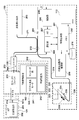
- FIG. 2 is a block configuration diagram of the diagnostic imaging apparatus 100.
- the functional configuration of the wavelength sweep type OCT will be described with reference to FIG.
- reference numeral 201 denotes a signal processing unit that controls the entire diagnostic imaging apparatus, and is composed of several circuits including a microprocessor.
- Reference numeral 210 denotes a non-volatile storage device represented by a hard disk, which stores various programs and data files executed by the signal processing unit 201.
- Reference numeral 202 denotes a memory (RAM) provided in the signal processing unit 201.
- a wavelength swept light source 203 is a light source that repeatedly generates light having a wavelength that changes within a preset range along the time axis.
- the light output from the wavelength swept light source 203 is incident on one end of the first single mode fiber 271 and transmitted toward the distal end side.
- the first single mode fiber 271 is optically coupled to the fourth single mode fiber 275 at an intermediate optical fiber coupler 272.
- the light incident on the first single mode fiber 271 and emitted from the optical fiber coupler 272 toward the front end is guided to the second single mode fiber 273 via the connector 105.
- the other end of the second single mode fiber 273 is connected to the optical rotary joint 230 in the motor drive unit 102.
- the probe 101 has an adapter 101 a for connecting to the motor drive unit 102. Then, the probe 101 is stably held by the motor driving unit 102 by connecting the probe 101 to the motor driving unit 102 by the adapter 101a. Further, a third single mode fiber 274 is accommodated in the imaging core 251 that is rotatably accommodated in the probe 101, and an end portion of the third single mode fiber 274 is connected to the optical rotary joint 230. . As a result, the second single mode fiber 273 and the third single mode fiber 274 are optically coupled.
- an optical transmission / reception unit 250 composed of a mirror and a lens that emits light in a direction substantially perpendicular to the rotation axis (details are shown in 3 will be described using 3a).
- the light emitted from the wavelength swept light source 203 passes through the first single mode fiber 271, the second single mode fiber 273, and the third single mode fiber 274 to the end of the third single mode fiber 274.
- the light is transmitted to the optical transceiver 250 provided in the unit.
- the optical transmission / reception unit 250 emits this light in a direction perpendicular to the axis of the third single mode fiber 274 and receives the reflected light. Then, the reflected light received by the optical transmission / reception unit 250 is guided in reverse and returned to the operation control device 103.
- an optical path length adjustment mechanism 220 that finely adjusts the optical path length of the reference light is provided at the opposite end of the fourth single mode fiber 275 coupled to the optical fiber coupler 272.
- the optical path length adjusting mechanism 220 functions as an optical path length changing unit that changes the optical path length corresponding to the variation in length so that the variation in length of each probe 101 can be absorbed when the probe 101 is replaced.
- a collimating lens 225 located at the end of the fourth single mode fiber 275 is provided on a movable uniaxial stage 224 as indicated by an arrow 226 in the optical axis direction.
- the uniaxial stage 224 functions as an optical path length changing unit having a variable range of the optical path length that can absorb the variation in the optical path length of the probe 101. Further, the uniaxial stage 224 also has a function as an adjusting means for adjusting the offset. For example, even when the tip of the probe 101 is not in close contact with the surface of the living tissue, the optical path length can be minutely changed by the uniaxial stage so as to interfere with the reflected light from the surface position of the living tissue. Is possible.
- the optical path length is finely adjusted by the uniaxial stage 224, and the light reflected by the mirror 223 via the grating 221 and the lens 222 is again guided to the fourth single mode fiber 275, and the second optical fiber coupler 272 performs the second operation. Is mixed with the light obtained from the single mode fiber 273 side and received as interference light by the photodiode portion (PD) 204.
- PD photodiode portion
- the interference light received by the photodiode unit 204 in this way is photoelectrically converted, amplified by the amplifier 205, and then input to the demodulator 206.
- the demodulator 206 performs demodulation processing for extracting only the signal portion of the interfered light, and its output is input to the A / D converter 207 as an interference light signal.
- the A / D converter 207 samples the interference light signal for 2048 points at 90 MHz, for example, and generates one line of digital data (interference light data).
- the sampling frequency of 90 MHz is based on the assumption that about 90% of the wavelength sweep cycle (25 ⁇ sec) is extracted as 2048 digital data when the wavelength sweep repetition frequency is 40 kHz. There is no particular limitation.
- the line-by-line interference light data generated by the A / D converter 207 is input to the signal processing unit 201 and temporarily stored in the memory 202.
- interference light data is frequency-resolved by FFT (Fast Fourier Transform) to generate data in the depth direction (line data).
- FFT Fast Fourier Transform
- the signal processing unit 201 constructs an optical cross-sectional image at each position in the blood vessel from the line data, and outputs it to the monitor 113 at a predetermined frame rate in some cases.
- the signal processing unit 201 is further connected to an optical path length adjustment driving unit 209 and a communication unit 208.
- the signal processing unit 201 controls the position of the uniaxial stage 224 (optical path length control) via the optical path length adjustment driving unit 209.
- the communication unit 208 incorporates several drive circuits and communicates with the motor drive unit 102 under the control of the signal processing unit 201. Specifically, a drive signal is supplied to the radial scanning motor for rotating the third single mode fiber by the optical rotary joint in the motor driving unit 102, and the encoder unit 242 for detecting the rotational position of the radial motor. Reception of the signal from the signal line, and supply of a drive signal to the linear drive unit 243 for pulling the third single mode fiber 274 at a predetermined speed.
- the above processing in the signal processing unit 201 is also realized by a predetermined program being executed by a computer.
- the signal processing unit 201 drives the wavelength swept light source 203 to drive the radial scanning motor 241 and the linear driving unit 243 (hereinafter, the radial scanning motor 241 and the linear driving unit). (Light irradiation and light reception processing by driving 243 is called scanning).
- the wavelength swept light is supplied from the wavelength swept light source 203 to the optical transmission / reception unit 250 at the tip of the imaging core 251 through the path as described above.
- the imaging core 251 moves along the rotation axis while rotating by the drive control of the motor drive unit 102.
- the light transmitting / receiving unit 250 also emits light to the vascular lumen surface and receives reflected light while rotating and moving along the blood vessel axis.
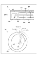
- the imaging core 251 includes a drive shaft 312 for accommodating the third single mode fiber 274 and transmitting the rotational force (arrow 302 in the figure) from the motor drive unit 102, and an optical transmission / reception unit 250 attached to the tip of the drive shaft 312. It is comprised with the housing 313 to accommodate.
- the one-dot chain line shown in the figure is the rotation center axis.
- the optical transmission / reception unit 250 moves in the catheter sheath 311.
- the optical transmission / reception unit 250 is composed of a hemispherical ball lens as shown in the figure.
- FIG. 3b of FIG. 3b is a diagram for explaining the reconstruction processing of the cross-sectional image of the lumen surface 351 of the blood vessel in which the optical transmission / reception unit 250 is located.
- the wavelength swept light source 203 generates light having a wavelength that varies along the time axis during a period in which the light transmitting / receiving unit 250 transmits and receives light once.
- the reflection intensity (or absorption amount) of light at each position in the radial direction from the rotational center position is obtained by performing FFT processing on one line of interference light data in the direction in which the light is irradiated by one transmission / reception of light.
- “Line data” is obtained. Accordingly, 512 line data extending radially from the rotation center 352 can be obtained by transmitting and receiving light 512 times, for example, during one rotation.
- the lens surface of the light transmitting / receiving unit 250 Although it is weak, reflection occurs on the lens surface of the light transmitting / receiving unit 250, the inner surface of the catheter sheath 311 and the boundary surfaces of the outer surface. That is, three circles appear in the vicinity of the rotation center position. Among these, the innermost circle 353 is caused by reflection on the lens surface of the optical transceiver 250.
- the basic configuration and functions of the diagnostic imaging apparatus 100 according to the embodiment have been described above. Next, detection of the ablation state by the diagnostic imaging apparatus 100 according to the embodiment will be described.
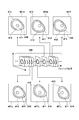
- FIG. 4 is a diagram schematically showing a group of cross-sectional images obtained by moving the imaging core 251 in the axial direction within the cauterized renal artery, and the axial position information (hereinafter referred to as pullback position) at that time.
- a plurality of cross-sectional images are arranged along the line.
- the linear drive unit 243 is configured by a pulse motor
- the pullback position is obtained by counting the drive pulses supplied to the pulse motor of the linear drive unit 243.
- the method of acquiring the pullback position is not limited to this, and for example, the pullback position may be acquired by providing a linear scale that moves in accordance with the position of the adapter and reading it with a sensor. As described above, a pullback position is added to each acquired cross-sectional image group.
- Each cross-sectional image constituting the cross-sectional image group 400 thus obtained includes a vascular tomographic image of the renal artery, and a vascular lumen wall and an external elastic plate can be observed from the vascular tomographic image.
- a vascular lumen wall and an external elastic plate can be observed from the vascular tomographic image.
- a continuous blood vessel lumen wall 412 and an outer elastic plate 411 are observed in the blood vessel tomographic image 410.
- the sympathetic nerve runs outside the outer elastic plate 411. Therefore, when the sympathetic nerve is cauterized through the lumen wall, the thermal energy is not only from the sympathetic nerve but also from the lumen wall and the sympathetic nerve. It is also applied to the outer elastic plate in between.
- the outer elastic plate to which heat energy is applied is denatured and cannot be observed on the cross-sectional image (specifically, the outer elastic plate to which heat energy is applied cannot be observed on the cross-sectional image due to degeneration. Decreases). Therefore, when the ablation position exists in the axial movement range (imaging range) of the imaging core 251, a part of the outer elastic plate 411 disappears in the vascular tomogram, and a cross-sectional image in which discontinuous portions exist is present. Will be acquired.
- disappearance occurs in the outer elastic plate 411 from the vascular tomographic image 410 of the cross-sectional image 401b. Thereafter, the discontinuous portion 413 occurs in the outer elastic plate 411 in the cross-sectional images 401c, 401d, and 401e acquired with the progress of the pullback position, and the discontinuous portion 413 in the outer elastic plate 411 disappears in the cross-sectional image 401f. ing. Therefore, in the example of FIG. 4, it can be seen that the outer elastic plate 411 has disappeared between the cross-sectional image 401b and the cross-sectional image 401e.
- the pullback position of the imaging core 251 is monitored, and the pullback position when each cross-sectional image is acquired can be determined. Therefore, the length of the blood vessel having the disappearing portion of the outer elastic plate can be determined from the difference between the pull-back positions of the cross-sectional image 401b where the disappearance of the outer elastic plate 411 starts and the cross-sectional image 401e where the disappearance of the outer elastic plate 411 ends.
- a range cautery range in which cauterization extends is estimated using this length and a model described below with reference to FIG. 5 to obtain the cautery depth.
- FIG. 5 is a diagram illustrating a model for estimating the ablation range.
- the length m of the disappearance portion is obtained from the difference between the pullback position 521 at the disappearance start and the pullback position 522 at the disappearance end.
- the difference between the pullback position of the cross-sectional image 401b and the pullback position of the cross-sectional image 401e is the length m of the disappearing portion.
- a semicircle 501 having a radius d and having a chord with a length m at the position t from the center is cauterized. Estimated range.
- the ablation catheter is estimated to be a semicircle centered on the inner surface of the blood vessel wall.
- the distance t from the lumen (inner wall surface) of the blood vessel to the outer elastic plate can be measured from the portion where the disappearance of the outer elastic plate has not occurred in the cross-sectional image.
- EEM External Elastic Membrane
- t the distance on the line between the position of the external elastic plate and the position of the blood vessel lumen wall determined using these methods.
- an average distance (may be age group or sex) of the outer elastic plate from the blood vessel lumen in the renal artery may be used.
- FIG. 6 is a diagram illustrating an example of a state in which the cross-sectional image 401d in the disappearance section illustrated in FIG.
- the cautery depth f at the pull-back position of the cross-sectional image 401d is calculated and displayed in the display area 601.
- a circumferential ablation range is detected based on a change in luminance value, and for example, a circumferential ablation range detected by an arrow 602 is clearly indicated.
- the ablation estimated range 603 may be displayed by connecting the point and both ends of the disappearance position and further extending to the lumen. Note that various methods such as linear and spline are conceivable for connecting the ends of the point and the disappearance position.
- a cross-sectional image for example, cross-sectional image 401a
- the display of the cauterization depth in the display area 601 and the cauterization range in the circumferential direction are displayed.
- the arrow 602 indicating is not displayed.
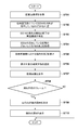
- FIG. 7 is a flowchart for explaining processing related to calculation and display of ablation depth among the processing executed by the microprocessor of the signal processing unit 201.
- step S701 the microprocessor acquires the cross-sectional image group 400 including a plurality of cross-sectional images at a plurality of pull-back positions as described in FIG. 4 by moving the imaging core 251 in the axial direction while performing radial scanning.
- FIG. 8 is a diagram illustrating a configuration example of data acquired in step S701. Each slice image of the slice image group 400 is stored in the memory 202 as frame data 801. At step S701, the cross-sectional image data 802 corresponding to each cross-sectional image and the pull-back position 803 at the time of acquisition of the cross-sectional image are recorded in the frame data 801.
- step S702 the microprocessor determines whether or not the outer elastic plate has disappeared for each of the cross-sectional image groups 400, and uses the determination result as an area of the disappearance occurrence 804 of each frame data (FIG. 8). ) The microprocessor detects the outer elastic plate for each cross-sectional image of the cross-sectional image group 400, and determines whether there is an interrupted portion (disappearance point) in the outer elastic plate.
- a position where the boundary where the luminance value first increases beyond a predetermined threshold appears is set as the position of the external elastic plate If the position of the external elastic plate specified using edge detection with Laplacian filter, Sobel filter, etc. is not within the specific depth range on the line, it is determined that the external elastic plate has disappeared.
- Each cross-sectional image may be displayed on the monitor 113, and the user may determine whether or not the outer elastic plate has disappeared by observing it. In this case, if the user designates “with disappearance” for each cross-sectional image in the disappearance section, the operation amount increases.
- the “exist” is automatically generated in the disappearance occurrence 804 of these cross-sectional images and all cross-sectional images (frame data) between them. May be written.
- the disappearance occurrence 804 of all the cross-sectional images 401b to 401e is set to “present”.
- step S703 the microprocessor refers to the disappearance occurrence 804 of the frame data 801 arranged in the order of the pull-back position (acquisition order), and the sectional image where the occurrence of the disappearance of the outer elastic plate has started and ended. Is identified. For example, at the portion where the frame data where the occurrence of erasure 804 is “Yes” continues, the first frame data is the start of erasure and the last frame data is the end of erasure. After that, in step S704, the microprocessor obtains the difference between the pullback position of the frame data where the disappearance of the outer elastic plate has started and the frame data where the outer elastic plate has ended, and determines the interval (disappearance interval) of the section where the outer elastic plate has partially disappeared. The distance, that is, the length m of the lost part is obtained. Since the pullback position is recorded in each frame data, the length m of the lost portion can be easily obtained by using this.
- step S705 the microprocessor calculates an ablation range for each cross-sectional image in the disappearance section using the model described in FIG. Then, the microprocessor calculates the ablation depth at the pullback position of each frame data (cross-sectional image) based on the ablation depth, and records it in the ablation depth 805 of the frame data. Note that the recording to the ablation depth 805 is performed on the frame data in which the disappearance occurrence 804 is “present”.
- step S707 when a cross-sectional image (frame data) to be displayed is selected, the microprocessor displays the cross-sectional image on the monitor 113. At this time, if the cross-sectional image to be displayed is a cross-sectional image of the disappearing section of the outer elastic plate, the process proceeds from step S709 to step S710, and the microprocessor determines the circumferential ablation range from the cross-sectional image. As shown in FIG. 6a, an ablation range 602 is displayed. In step S710, the microprocessor reads the ablation depth 805 of the frame data, and displays it in the display area 601 as “the ablation depth”.
- step S708 If the cross-sectional image to be displayed is not an image of the disappearance section, the process ends as it is from step S708, and the circumferential cautery range and irradiation zone depth are not displayed as described above, and 6b in FIG. You will get a display like
- the ablation catheter for cutting the sympathetic nerve and the probe 101 described above may be simultaneously inserted into the renal artery, and repeated OCT imaging may be performed during ablation with the ablation catheter to determine completion of ablation. .
- the microprocessor determines that the ablation has been completed and notifies the user to that effect.
- the disappearing section includes a frame where the disappearing portion has started to appear (cross-sectional image 401b in FIG. 4), and a frame immediately before the first frame in which the disappearing portion disappeared (cross-sectional image 401e in FIG. 4).
- the frame is between, but is not limited to this.
- the frame immediately before the frame where the disappearing portion starts to appear cross-sectional image 401a
- the first frame where the disappearing portion disappears cross-sectional image 401f
- the frame between them may be used as the disappearing section.
- a cautery catheter for cutting the sympathetic nerve is inserted to cauterize the lumen wall of the renal artery, and then The above-described cauterization depth may be calculated by inserting the probe 101 and performing OCT imaging.
- the cauterization depth of the renal artery sympathetic nerve can be determined more accurately by mapping the calculated cauterization depth to the position information of the nerve of the renal artery.
Landscapes
- Health & Medical Sciences (AREA)
- Life Sciences & Earth Sciences (AREA)
- Engineering & Computer Science (AREA)
- Surgery (AREA)
- Physics & Mathematics (AREA)
- Medical Informatics (AREA)
- Public Health (AREA)
- Veterinary Medicine (AREA)
- Pathology (AREA)
- General Health & Medical Sciences (AREA)
- Biomedical Technology (AREA)
- Heart & Thoracic Surgery (AREA)
- Biophysics (AREA)
- Molecular Biology (AREA)
- Animal Behavior & Ethology (AREA)
- Nuclear Medicine, Radiotherapy & Molecular Imaging (AREA)
- Radiology & Medical Imaging (AREA)
- Optics & Photonics (AREA)
- Computer Vision & Pattern Recognition (AREA)
- General Physics & Mathematics (AREA)
- Theoretical Computer Science (AREA)
- Quality & Reliability (AREA)
- Endoscopes (AREA)
- Instruments For Viewing The Inside Of Hollow Bodies (AREA)
- Image Processing (AREA)
- Ultra Sonic Daignosis Equipment (AREA)
- Investigating Or Analysing Materials By Optical Means (AREA)
Abstract
L'invention concerne un dispositif de traitement d'image qui traite une pluralité d'images en coupe transversale obtenues par tomographie à cohérence optique (OCT) par rotation d'un noyau d'imagerie et déplacement de celui-ci à l'intérieur d'un cathéter dans la direction axiale, où le dispositif de traitement d'image: stocke des données concernant les images de section transversale en les associant à l'information concernant la position dans la direction axiale au moment auquel chaque image en coupe transversale a été obtenue; extrait, à partir d'une pluralité d'images en coupe transversale, une première image en coupe transversale où une section disparaissant dans laquelle on détermine le début de la disparition d'une partie d'une membrane élastique externe contenue dans une image tomographique vasculaire, et une seconde image en coupe transversale où la section disparaissant se termine; et obtient l'information stockée concernant la position dans la direction axiale pour la première image en coupe transversale et la seconde image en coupe transversale et calcule ensuite, sur la base de la différence d'information concernant la position dans la direction axiale, une plage d'ablation, sur laquelle l'ablation s'étend, dans l'emplacement correspondant à la section disparaissant.
Priority Applications (4)
| Application Number | Priority Date | Filing Date | Title |
|---|---|---|---|
| CN201680019756.8A CN107427191B (zh) | 2015-03-30 | 2016-03-23 | 图像处理装置和方法、程序 |
| EP16772474.9A EP3278713B1 (fr) | 2015-03-30 | 2016-03-23 | Dispositif et procédé de traitement d'image oct |
| JP2017509841A JP6674447B2 (ja) | 2015-03-30 | 2016-03-23 | 画像処理装置および方法、プログラム |
| US15/719,837 US10559077B2 (en) | 2015-03-30 | 2017-09-29 | Image processing apparatus, image processing method, and program |
Applications Claiming Priority (2)
| Application Number | Priority Date | Filing Date | Title |
|---|---|---|---|
| JP2015068626 | 2015-03-30 | ||
| JP2015-068626 | 2015-03-30 |
Related Child Applications (1)
| Application Number | Title | Priority Date | Filing Date |
|---|---|---|---|
| US15/719,837 Continuation US10559077B2 (en) | 2015-03-30 | 2017-09-29 | Image processing apparatus, image processing method, and program |
Publications (1)
| Publication Number | Publication Date |
|---|---|
| WO2016158593A1 true WO2016158593A1 (fr) | 2016-10-06 |
Family
ID=57006766
Family Applications (1)
| Application Number | Title | Priority Date | Filing Date |
|---|---|---|---|
| PCT/JP2016/059088 Ceased WO2016158593A1 (fr) | 2015-03-30 | 2016-03-23 | Dispositif et procédé de traitement d'image, et programme |
Country Status (5)
| Country | Link |
|---|---|
| US (1) | US10559077B2 (fr) |
| EP (1) | EP3278713B1 (fr) |
| JP (1) | JP6674447B2 (fr) |
| CN (1) | CN107427191B (fr) |
| WO (1) | WO2016158593A1 (fr) |
Cited By (1)
| Publication number | Priority date | Publication date | Assignee | Title |
|---|---|---|---|---|
| WO2022070275A1 (fr) * | 2020-09-29 | 2022-04-07 | オリンパス株式会社 | Dispositif de support, système endoscopique, procédé de support et programme |
Families Citing this family (3)
| Publication number | Priority date | Publication date | Assignee | Title |
|---|---|---|---|---|
| JP6440136B1 (ja) * | 2018-09-06 | 2018-12-19 | 株式会社Medi Plus | 医療映像スイッチャー |
| US12076118B2 (en) * | 2021-10-01 | 2024-09-03 | Canon U.S.A., Inc. | Devices, systems, and methods for detecting external elastic lamina (EEL) from intravascular OCT images |
| CN116492049B (zh) * | 2023-06-29 | 2023-10-03 | 北京智愈医疗科技有限公司 | 一种前列腺适形消融范围的确定方法及装置 |
Citations (5)
| Publication number | Priority date | Publication date | Assignee | Title |
|---|---|---|---|---|
| JP2008543511A (ja) * | 2005-06-24 | 2008-12-04 | ヴォルケイノウ・コーポレーション | 脈管の画像作製方法 |
| JP2010042182A (ja) * | 2008-08-18 | 2010-02-25 | Fujifilm Corp | レーザ治療装置 |
| JP2012157384A (ja) * | 2011-01-28 | 2012-08-23 | Fujifilm Corp | 診断支援装置、診断支援方法、病変部検出装置、及び病変部検出方法 |
| JP2012200532A (ja) * | 2011-03-28 | 2012-10-22 | Terumo Corp | 画像診断装置及び表示方法 |
| WO2014068606A1 (fr) * | 2012-10-29 | 2014-05-08 | テルモ株式会社 | Dispositif du type insertion dans des vaisseaux |
Family Cites Families (14)
| Publication number | Priority date | Publication date | Assignee | Title |
|---|---|---|---|---|
| DE10355275B4 (de) * | 2003-11-26 | 2009-03-05 | Siemens Ag | Kathedereinrichtung |
| CN101686827B (zh) * | 2007-01-19 | 2014-08-13 | 桑尼布鲁克健康科学中心 | 具有组合的超声和光学成像装置的成像探头 |
| US20100168739A1 (en) * | 2008-12-31 | 2010-07-01 | Ardian, Inc. | Apparatus, systems, and methods for achieving intravascular, thermally-induced renal neuromodulation |
| US9089331B2 (en) * | 2009-07-31 | 2015-07-28 | Case Western Reserve University | Characterizing ablation lesions using optical coherence tomography (OCT) |
| CN102740925B (zh) * | 2009-10-12 | 2015-02-18 | 科纳医药股份有限公司 | 神经的能量调节 |
| JP5508092B2 (ja) * | 2010-03-30 | 2014-05-28 | テルモ株式会社 | 光画像診断装置及びその表示制御方法 |
| EP2443992A2 (fr) * | 2010-10-25 | 2012-04-25 | Fujifilm Corporation | Appareil de support de diagnostic, procédé de support de diagnostic, appareil de détection de lésions et procédé de détection de lésions |
| WO2012100211A2 (fr) * | 2011-01-20 | 2012-07-26 | Hansen Medical, Inc. | Système et procédé de thérapie endoluminale et transluminale |
| US8545409B2 (en) * | 2011-04-14 | 2013-10-01 | St. Jude Medical, Inc. | Arrangement and interface for RF ablation system with acoustic feedback |
| JP5305187B1 (ja) | 2011-12-27 | 2013-10-02 | 東洋紡株式会社 | 感光性印刷原版の現像方法及び現像装置 |
| WO2014045327A1 (fr) * | 2012-09-24 | 2014-03-27 | テルモ株式会社 | Appareil de diagnostic par imagerie et procédé de traitement d'image |
| US9301795B2 (en) * | 2012-10-29 | 2016-04-05 | Ablative Solutions, Inc. | Transvascular catheter for extravascular delivery |
| CA2913346A1 (fr) * | 2013-06-05 | 2014-12-11 | Metavention, Inc. | Modulation de fibres nerveuses ciblees |
| CN104200465B (zh) * | 2014-08-20 | 2017-08-25 | 沈阳东软医疗系统有限公司 | 心脏三维图像的分割方法和装置 |
-
2016
- 2016-03-23 WO PCT/JP2016/059088 patent/WO2016158593A1/fr not_active Ceased
- 2016-03-23 EP EP16772474.9A patent/EP3278713B1/fr active Active
- 2016-03-23 CN CN201680019756.8A patent/CN107427191B/zh active Active
- 2016-03-23 JP JP2017509841A patent/JP6674447B2/ja active Active
-
2017
- 2017-09-29 US US15/719,837 patent/US10559077B2/en active Active
Patent Citations (5)
| Publication number | Priority date | Publication date | Assignee | Title |
|---|---|---|---|---|
| JP2008543511A (ja) * | 2005-06-24 | 2008-12-04 | ヴォルケイノウ・コーポレーション | 脈管の画像作製方法 |
| JP2010042182A (ja) * | 2008-08-18 | 2010-02-25 | Fujifilm Corp | レーザ治療装置 |
| JP2012157384A (ja) * | 2011-01-28 | 2012-08-23 | Fujifilm Corp | 診断支援装置、診断支援方法、病変部検出装置、及び病変部検出方法 |
| JP2012200532A (ja) * | 2011-03-28 | 2012-10-22 | Terumo Corp | 画像診断装置及び表示方法 |
| WO2014068606A1 (fr) * | 2012-10-29 | 2014-05-08 | テルモ株式会社 | Dispositif du type insertion dans des vaisseaux |
Non-Patent Citations (2)
| Title |
|---|
| HIROSHI SUZUMURA ET AL.: "Role of Rotational Atherectomy for Calcific Coronary Lesions in Determining the Initial and Long Term Outcomes of Stenting Evaluated by IVUS", JAPANESE JOURNAL OF INTERVENTIONAL CARDIOLOGY, vol. 15, no. 1, 2000, pages 32 - 40, XP009506643, ISSN: 0914-8922 * |
| See also references of EP3278713A4 * |
Cited By (1)
| Publication number | Priority date | Publication date | Assignee | Title |
|---|---|---|---|---|
| WO2022070275A1 (fr) * | 2020-09-29 | 2022-04-07 | オリンパス株式会社 | Dispositif de support, système endoscopique, procédé de support et programme |
Also Published As
| Publication number | Publication date |
|---|---|
| JP6674447B2 (ja) | 2020-04-01 |
| US10559077B2 (en) | 2020-02-11 |
| EP3278713B1 (fr) | 2020-01-01 |
| US20180025481A1 (en) | 2018-01-25 |
| EP3278713A1 (fr) | 2018-02-07 |
| EP3278713A4 (fr) | 2018-12-12 |
| JPWO2016158593A1 (ja) | 2018-02-01 |
| CN107427191B (zh) | 2019-09-13 |
| CN107427191A (zh) | 2017-12-01 |
Similar Documents
| Publication | Publication Date | Title |
|---|---|---|
| JP5485760B2 (ja) | 光干渉断層像形成装置及びその制御方法 | |
| US10238816B2 (en) | Devices and methods for forming vascular access | |
| JP4768494B2 (ja) | 画像診断装置およびその処理方法 | |
| JP5592137B2 (ja) | 光画像診断装置及びその表示制御方法 | |
| JP6533078B2 (ja) | 画像診断装置、その制御方法、プログラム及びコンピュータ可読記憶媒体 | |
| JP5689728B2 (ja) | 光干渉断層像形成装置及びその制御方法 | |
| JP5628785B2 (ja) | 画像診断装置 | |
| JP6095770B2 (ja) | 画像診断装置及びその作動方法、プログラム及びコンピュータ可読記憶媒体 | |
| WO2019046155A1 (fr) | Sonde d'imagerie à fibre optique ayant un déclencheur de retrait de mode de gaine, et son procédé de commande | |
| JP2016507272A (ja) | 機能的利得の測定技術及び表示 | |
| JP2018512961A (ja) | デュアルルーメン診断カテーテル | |
| JP5508092B2 (ja) | 光画像診断装置及びその表示制御方法 | |
| JP6284944B2 (ja) | 画像診断装置及びその作動方法及び記憶媒体 | |
| WO2014136137A1 (fr) | Appareil d'imagerie diagnostique, dispositif de traitement des informations et procédés de commande, programmes et support de stockage lisible par ordinateur associés | |
| JP6674447B2 (ja) | 画像処理装置および方法、プログラム | |
| JP6100911B2 (ja) | 画像診断装置及びその作動方法 | |
| JP6669720B2 (ja) | 画像診断装置、その作動方法、プログラム及びコンピュータ可読記憶媒体 | |
| JP6514562B2 (ja) | 画像処理装置および方法、プログラム | |
| JP6809905B2 (ja) | 画像診断装置、画像診断装置の作動方法及びプログラム | |
| JP2017127533A (ja) | 光干渉断層装置、光干渉断層装置の制御方法及びプログラム | |
| JP6584806B2 (ja) | 画像診断装置及びその制御方法、プログラム及びコンピュータ可読記憶媒体 | |
| JP2016182303A (ja) | 画像診断装置及びその制御方法、プログラム及びコンピュータ可読記憶媒体 |
Legal Events
| Date | Code | Title | Description |
|---|---|---|---|
| 121 | Ep: the epo has been informed by wipo that ep was designated in this application |
Ref document number: 16772474 Country of ref document: EP Kind code of ref document: A1 |
|
| REEP | Request for entry into the european phase |
Ref document number: 2016772474 Country of ref document: EP |
|
| ENP | Entry into the national phase |
Ref document number: 2017509841 Country of ref document: JP Kind code of ref document: A |
|
| NENP | Non-entry into the national phase |
Ref country code: DE |