WO2016158833A1 - アキュムレータ - Google Patents
アキュムレータ Download PDFInfo
- Publication number
- WO2016158833A1 WO2016158833A1 PCT/JP2016/059849 JP2016059849W WO2016158833A1 WO 2016158833 A1 WO2016158833 A1 WO 2016158833A1 JP 2016059849 W JP2016059849 W JP 2016059849W WO 2016158833 A1 WO2016158833 A1 WO 2016158833A1
- Authority
- WO
- WIPO (PCT)
- Prior art keywords
- metal bellows
- damping member
- accumulator
- bellows
- pressure vessel
- Prior art date
- Legal status (The legal status is an assumption and is not a legal conclusion. Google has not performed a legal analysis and makes no representation as to the accuracy of the status listed.)
- Ceased
Links
Images


Classifications
-
- F—MECHANICAL ENGINEERING; LIGHTING; HEATING; WEAPONS; BLASTING
- F15—FLUID-PRESSURE ACTUATORS; HYDRAULICS OR PNEUMATICS IN GENERAL
- F15B—SYSTEMS ACTING BY MEANS OF FLUIDS IN GENERAL; FLUID-PRESSURE ACTUATORS, e.g. SERVOMOTORS; DETAILS OF FLUID-PRESSURE SYSTEMS, NOT OTHERWISE PROVIDED FOR
- F15B1/00—Installations or systems with accumulators; Supply reservoir or sump assemblies
- F15B1/02—Installations or systems with accumulators
- F15B1/04—Accumulators
- F15B1/08—Accumulators using a gas cushion; Gas charging devices; Indicators or floats therefor
- F15B1/10—Accumulators using a gas cushion; Gas charging devices; Indicators or floats therefor with flexible separating means
- F15B1/12—Accumulators using a gas cushion; Gas charging devices; Indicators or floats therefor with flexible separating means attached at their periphery
- F15B1/14—Accumulators using a gas cushion; Gas charging devices; Indicators or floats therefor with flexible separating means attached at their periphery by means of a rigid annular supporting member
-
- F—MECHANICAL ENGINEERING; LIGHTING; HEATING; WEAPONS; BLASTING
- F15—FLUID-PRESSURE ACTUATORS; HYDRAULICS OR PNEUMATICS IN GENERAL
- F15B—SYSTEMS ACTING BY MEANS OF FLUIDS IN GENERAL; FLUID-PRESSURE ACTUATORS, e.g. SERVOMOTORS; DETAILS OF FLUID-PRESSURE SYSTEMS, NOT OTHERWISE PROVIDED FOR
- F15B1/00—Installations or systems with accumulators; Supply reservoir or sump assemblies
- F15B1/02—Installations or systems with accumulators
- F15B1/04—Accumulators
- F15B1/08—Accumulators using a gas cushion; Gas charging devices; Indicators or floats therefor
- F15B1/10—Accumulators using a gas cushion; Gas charging devices; Indicators or floats therefor with flexible separating means
- F15B1/103—Accumulators using a gas cushion; Gas charging devices; Indicators or floats therefor with flexible separating means the separating means being bellows
-
- F—MECHANICAL ENGINEERING; LIGHTING; HEATING; WEAPONS; BLASTING
- F16—ENGINEERING ELEMENTS AND UNITS; GENERAL MEASURES FOR PRODUCING AND MAINTAINING EFFECTIVE FUNCTIONING OF MACHINES OR INSTALLATIONS; THERMAL INSULATION IN GENERAL
- F16F—SPRINGS; SHOCK-ABSORBERS; MEANS FOR DAMPING VIBRATION
- F16F9/00—Springs, vibration-dampers, shock-absorbers, or similarly-constructed movement-dampers using a fluid or the equivalent as damping medium
- F16F9/06—Springs, vibration-dampers, shock-absorbers, or similarly-constructed movement-dampers using a fluid or the equivalent as damping medium using both gas and liquid
- F16F9/08—Springs, vibration-dampers, shock-absorbers, or similarly-constructed movement-dampers using a fluid or the equivalent as damping medium using both gas and liquid where gas is in a chamber with a flexible wall
- F16F9/096—Springs, vibration-dampers, shock-absorbers, or similarly-constructed movement-dampers using a fluid or the equivalent as damping medium using both gas and liquid where gas is in a chamber with a flexible wall comprising a hydropneumatic accumulator of the membrane type provided on the upper or the lower end of a damper or separately from or laterally on the damper
-
- F—MECHANICAL ENGINEERING; LIGHTING; HEATING; WEAPONS; BLASTING
- F15—FLUID-PRESSURE ACTUATORS; HYDRAULICS OR PNEUMATICS IN GENERAL
- F15B—SYSTEMS ACTING BY MEANS OF FLUIDS IN GENERAL; FLUID-PRESSURE ACTUATORS, e.g. SERVOMOTORS; DETAILS OF FLUID-PRESSURE SYSTEMS, NOT OTHERWISE PROVIDED FOR
- F15B2201/00—Accumulators
- F15B2201/20—Accumulator cushioning means
- F15B2201/205—Accumulator cushioning means using gas
-
- F—MECHANICAL ENGINEERING; LIGHTING; HEATING; WEAPONS; BLASTING
- F15—FLUID-PRESSURE ACTUATORS; HYDRAULICS OR PNEUMATICS IN GENERAL
- F15B—SYSTEMS ACTING BY MEANS OF FLUIDS IN GENERAL; FLUID-PRESSURE ACTUATORS, e.g. SERVOMOTORS; DETAILS OF FLUID-PRESSURE SYSTEMS, NOT OTHERWISE PROVIDED FOR
- F15B2201/00—Accumulators
- F15B2201/30—Accumulator separating means
- F15B2201/315—Accumulator separating means having flexible separating means
- F15B2201/3153—Accumulator separating means having flexible separating means the flexible separating means being bellows
-
- F—MECHANICAL ENGINEERING; LIGHTING; HEATING; WEAPONS; BLASTING
- F15—FLUID-PRESSURE ACTUATORS; HYDRAULICS OR PNEUMATICS IN GENERAL
- F15B—SYSTEMS ACTING BY MEANS OF FLUIDS IN GENERAL; FLUID-PRESSURE ACTUATORS, e.g. SERVOMOTORS; DETAILS OF FLUID-PRESSURE SYSTEMS, NOT OTHERWISE PROVIDED FOR
- F15B2201/00—Accumulators
- F15B2201/30—Accumulator separating means
- F15B2201/315—Accumulator separating means having flexible separating means
- F15B2201/3158—Guides for the flexible separating means, e.g. for a collapsed bladder
Definitions
- the present invention relates to an accumulator that is used for releasing a large amount of energy in a short time or for reducing pressure fluctuations.
- an accumulator provided with a metal bellows is used to release a large amount of energy in a short period of time or to relieve pressure fluctuations.
- a sliding ring having a bearing function at the tip of the metal bellows is provided. Is provided.
- the sliding ring alone may not be sufficient under various conditions such as the length of the metal bellows. Therefore, an intermediate ring (vibration control member) that exhibits the same function as the sliding ring may be provided at an intermediate position in the axial direction of the metal bellows.
- FIG. 11 is a schematic cross-sectional view of an accumulator according to a conventional example.
- the accumulator 500 includes a pressure vessel (shell) 510 and a port forming member 520 provided so as to close the opening of the pressure vessel 510 and having a port.
- a metal bellows 530 that is a component of a partition unit that divides the space in the vessel into a gas chamber (G) in which gas is sealed and a fluid chamber (L) in which the working fluid flows. Is provided.
- a sliding ring 540 having a bearing function is provided at the tip of the metal bellows 530. The sliding ring 540 is configured such that its outer peripheral surface is slidable with respect to the inner peripheral surface of the pressure vessel 510.
- the metal bellows 530 can expand and contract smoothly, and vibration of the metal bellows 530 is suppressed.
- the vicinity of the middle of the metal bellows 530 may collide with the inner peripheral surface of the pressure vessel 510. Therefore, in this conventional example, an intermediate ring (damping member) 590 is provided at an intermediate position in the axial direction of the metal bellows 530.
- the intermediate ring 590 includes a thin annular body portion 591 and a guide portion 592 having a width in the expansion / contraction direction (equal to the axial direction) of the metal bellows 530 wider than the width of the body portion 591.
- a plurality of guide portions 592 are provided on the outer side in the radial direction of the body portion 591 at intervals in the circumferential direction.
- the radially outer surface of the guide portion 592 is configured to be slidable with respect to the inner peripheral surface of the pressure vessel 510. Thereby, the function of guiding the movement of the body portion 591 is exhibited.
- the intermediate ring 590 configured as described above exhibits the same function as the sliding ring 540. Therefore, even near the middle of the metal bellows 530, the metal bellows 530 expands and contracts smoothly, and vibration of the metal bellows 530 is suppressed.
- the intermediate ring 590 according to the conventional example, a gap is formed between the distal end on the radially inner side of the body portion 591 and the valley portion in the metal bellows 530. Further, the tip of the peak portion of the metal bellows 530 is configured to abut against the radially inner surface of the guide portion 592. Therefore, when the intermediate ring 590 receives an impact from the inner peripheral surface of the pressure vessel 510 due to the vibration of the metal bellows 530, the impact is not alleviated via the guide portion 592 of the intermediate ring 590, and the metal The impact was transmitted to the peak of the bellows 530. Therefore, the peak portion of the metal bellows 530 may be deformed or damaged.
- the gap between the abdominal portions of the metal bellows 530 is narrowed. Therefore, it is necessary to reduce the thickness of the body portion 591 in the intermediate ring 590 (corresponding to the width in the expansion / contraction direction (equal to the axial direction) in the metal bellows 530) so that the expansion / contraction of the metal bellows 530 is not affected.
- the metal bellows 530 is extended, a large gap is formed between the abdomen of the metal bellows 530 and the body portion 591 of the intermediate ring 590, so that the mounting state of the intermediate ring 590 is unstable, and further sliding There was no time stability.
- An object of the present invention is to provide an accumulator that stabilizes the mounting state of the vibration damping member while reducing the impact on the metal bellows.
- the present invention employs the following means in order to solve the above problems.
- the accumulator of the present invention is A pressure vessel; A partition unit provided in the pressure vessel and partitioned into a gas chamber sealed with gas and a fluid chamber through which a working fluid flows; With The partition unit includes a metal bellows that expands and contracts according to the pressure in the gas chamber and the pressure in the fluid chamber, The metal bellows in which a plurality of annular crests and a plurality of annular troughs are alternately formed is configured to be slidable on the inner peripheral surface of the pressure vessel in at least one of the plurality of annular troughs.
- the damping member is characterized in that a radially inner tip is fitted to the valley, and a radially outer tip is longer radially outward than a peak of the metal bellows.
- the vibration damping member can suppress the metal bellows from directly striking the inner peripheral surface of the pressure vessel, and can suppress the vibration of the metal bellows.
- the damping member is configured such that the radially inner tip is fitted to the valley of the metal bellows and the radially outer tip is longer radially outward than the peak of the metal bellows. . Therefore, even when the damping member receives an impact from the inner peripheral surface of the pressure vessel, it is possible to suppress the impact from being transmitted to the peak portion of the metal bellows.
- the damping member receives an impact from the inner peripheral surface of the pressure vessel, the impact is transmitted to the valley portion of the metal bellows.
- the impact is transmitted through the entire damping member, the impact can be sufficiently mitigated as compared with the case where the impact is transmitted from the guide portion 592 of the intermediate ring 590 to the peak portion as in the conventional example.
- the damping member has a radially inner tip fitted to the valley portion of the metal bellows, the mounting state on the metal bellows can be stabilized.
- the damping member is A body portion extending in the circumferential direction; A fitted portion that is provided on the radially inner side of the body portion and is fitted to the valley portion; With The vibration damping member may be positioned and fixed to the metal bellows so that a gap is formed between the metal bellows and the body portion regardless of the stretched state of the metal bellows.
- the width of the metal bellows in the expansion / contraction direction is wider than the width of the body part, and a plurality of guide parts for guiding the movement of the body part are provided at intervals in the circumferential direction. It is good to have.
- the thickness of the guide portion may be set to a thickness that does not contact the tip of the peak portion of the metal bellows regardless of the stretched state of the metal bellows.
- FIG. 1 is a schematic cross-sectional view of an accumulator according to Embodiment 1 of the present invention.
- FIG. 2 is a schematic cross-sectional view of the accumulator according to the first embodiment of the present invention.
- FIG. 3 is a partially enlarged view of a schematic cross-sectional view of the accumulator according to the first embodiment of the present invention.
- FIG. 4 is a plan view of the vibration damping member according to Embodiment 1 of the present invention.
- FIG. 5 is a side view of the vibration damping member according to Embodiment 1 of the present invention.
- FIG. 6 is a schematic cross-sectional view of an accumulator according to Embodiment 2 of the present invention.
- FIG. 7 is a schematic cross-sectional view of an accumulator according to Embodiment 3 of the present invention.
- FIG. 8 is a schematic cross-sectional view of an accumulator according to Embodiment 4 of the present invention.
- FIG. 9 is a schematic cross-sectional view of an accumulator according to Embodiment 5 of the present invention.
- 10 is a schematic cross-sectional view of an accumulator according to Example 6 of the present invention.
- FIG. 11 is a schematic cross-sectional view of an accumulator according to a conventional example.
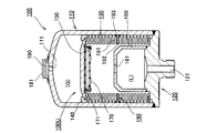
- FIGS. 1 and 2 are schematic cross-sectional views of an accumulator according to Embodiment 1 of the present invention.
- FIG. 1 shows a state in which the metal bellows is extended
- FIG. 2 shows a state in which the metal bellows is contracted.
- FIG. 3 is a partially enlarged view of the schematic cross-sectional view of the accumulator according to the first embodiment of the present invention, and is an enlarged cross-sectional view of the vicinity where the damping member is mounted.
- FIG. 4 is a plan view of the vibration damping member according to Embodiment 1 of the present invention.
- FIG. 5 is a side view of the vibration damping member according to the first embodiment of the present invention, and is a view of the vibration damping member as viewed from the outer peripheral surface side.
- the accumulator 100 according to the present embodiment can be used for releasing a large amount of energy in a short time, reducing pressure fluctuation, or the like. As a more specific example, it can be used to relieve pulsation in a pipe through which oil flows in an automobile. Moreover, the accumulator 100 according to the present embodiment has a rotationally symmetric shape with respect to the central axis.
- the accumulator 100 is a port formation having a substantially bottomed cylindrical pressure vessel (shell) 110 and a port 121 that is provided so as to close the opening of the pressure vessel 110 and serves as an inlet / outlet of the working fluid. Member 120.
- a through hole 111 for injecting gas is provided on the bottom side of the pressure vessel 110. After the gas is injected, the plug 180 is press-fitted into the through hole 111.
- the plug guide 181 is fixed to the bottom surface of the pressure vessel 110 so that the plug 180 is not easily removed after the plug 180 is press-fitted, and so that an accumulator mounting tool can be mounted.
- a partition unit 100U that divides the space in the vessel into a gas chamber (G) in which gas is sealed and a fluid chamber (L) in which a working fluid flows.
- the partition unit 100U includes a metal bellows 130 and a bellows cap 150 fixed to the metal bellows 130.
- the metal bellows 130 is a bellows-like and substantially cylindrical member in which a plurality of annular peaks (near the outer diameter tip of the bellows) and a plurality of annular valleys (near the inner diameter tip of the bellows) are alternately formed. Further, one end side of the metal bellows 130 is fixed to the port forming member 120, and the bellows cap 150 is fixed to the other end side.
- the partition unit 100U configured in this manner divides the space in the pressure vessel 110 into a gas chamber (G) and a fluid chamber (L).
- a certain amount of gas is sealed in the gas chamber (G).
- the fluid pressure in the fluid chamber (L) varies depending on the flow of the working fluid.
- the metal bellows 130 expands and contracts so that the atmospheric pressure in the gas chamber (G) and the fluid pressure in the fluid chamber (L) are kept in equilibrium.
- a seal member 170 is fixed to the bellows cap 150 by a seal holder 171.
- a substantially bottomed cylindrical member 160 is provided inside the metal bellows 130.
- the substantially bottomed cylindrical member 160 is fixed to the port forming member 120 at the open end side.
- a through hole 161 is provided on the bottom side of the substantially bottomed cylindrical member 160.
- a part of the working fluid flowing into the fluid chamber (L) is formed by the outer peripheral surface of the substantially bottomed cylindrical member 160, the seal member 170, the inner peripheral surface of the metal bellows 130, and the like. It becomes a state confined in the annular space. Therefore, the state in which the fluid pressure in the annular space and the air pressure on the outer peripheral surface side of the metal bellows 130 are substantially equal is maintained, and deformation of the metal bellows 130 is suppressed.
- a sliding ring 140 having a bearing function is provided at the tip of the metal bellows 130.
- the sliding ring 140 is configured such that its outer peripheral surface is slidable with respect to the inner peripheral surface of the pressure vessel 110.
- the metal bellows 130 can expand and contract smoothly, and vibration of the metal bellows 130 is suppressed.
- the vicinity of the middle of the metal bellows 130 may collide with the inner peripheral surface of the pressure vessel 110. Therefore, in this embodiment, a resin damping member 190 is provided at a position in the middle of the metal bellows 130 in the axial direction (in this embodiment, the center of the metal bellows 130 in the axial direction).
- the material for the vibration damping member 190 include polyamide, polytetrafluoroethylene, phenol resin (bakelite), and polyester plastic. Further, the material of the vibration damping member 190 is not limited to resin, and brass, rubber, or a metal whose surface is coated with a sliding material (such as brass or aluminum) can also be used.
- the vibration damping member 190 can also be configured from resin, rubber, brass, or the like (for example, a configuration that is mostly made of rubber and brass and uses a resin material for the sliding portion).
- the vibration damping member 190 will be described in detail with reference to FIGS.
- the damping member 190 is configured to be slidable on the inner peripheral surface of the pressure vessel 110. Further, the vibration damping member 190 plays a role of suppressing vibration of the metal bellows 130 while maintaining a gap between the metal bellows 130 and the inner peripheral surface of the pressure vessel 110.
- the damping member 190 according to the present embodiment is configured such that the radially inner tip is fitted to the trough 131b in the metal bellows 130.
- the vibration damping member 190 according to the present embodiment is provided on the inner side in the radial direction of the body portion 191 extending in the circumferential direction and the trough portion 131b in the metal bellows 130. And a fitted portion 192. Further, in the vibration damping member 190 according to the present embodiment, the guide portion 193 whose width in the expansion / contraction direction (equal to the axial direction) of the metal bellows 130 is wider than the width of the body portion 191 outside the body portion 191 in the radial direction. Is provided.
- the guide portion 193 plays a role of guiding the movement of the body portion 191, and a plurality of guide portions 193 are provided on the outer side in the radial direction of the body portion 191 at intervals in the circumferential direction. In this embodiment, five guide portions 193 are provided, but the number of guide portions 193 can be set as appropriate. Further, the outer peripheral surface of the guide portion 193 and the body portion 191 where the guide portion 193 is not provided is designed such that a slight gap is formed between the outer peripheral surface and the inner peripheral surface of the pressure vessel 110 ( (See FIG. 3). In addition, not only this shape but the trunk
- the body portion 191 is configured by a thin annular portion. Further, in order to facilitate the attachment of the damping member 190 to the metal bellows 130, a cutting portion C is provided at one place in the circumferential direction of the body portion 191. However, if there is no problem in attachment, this cutting part C may not be provided. Moreover, after attaching the damping member 190 to the metal bellows 130, the ends on both sides of the cut portion C may be joined together.
- the body portion 191 is formed in a substantially annular shape, but may be formed in an arc shape.
- the angle of the arc is less than 180 °, it is necessary to attach the plurality of vibration damping members 190 so that the attachment positions in the circumferential direction are different so that the metal bellows 130 does not collide with the inner peripheral surface of the pressure vessel 110. There is. Further, when only one damping member 190 is used, it is necessary that the angle of the arc exceeds 180 °. In the case where the arcuate body portion 191 is employed, there is an advantage that the damping member 190 can be easily attached to the metal bellows 130.
- the damping member 190 is separated from the tip of the peak 131a in the metal bellows 130 by fitting the fitted portion 192 at the tip in the radial direction to the valley 131b in the metal bellows 130. Positioned and fixed in the above state. Note that, by setting the inner diameter of the fitted portion 192 to be smaller than the outer diameter of the valley portion 131b, the tip of the fitted portion 192 is pressed against the valley portion 131b. Thereby, the damping member 190 is fixed in a state where it is positioned with respect to the metal bellows 130.
- the radial length of the body portion 191 in the damping member 190 is the radial distance from the tip of the peak portion 131a to the bottom of the valley portion 131b in the metal bellows 130 (the longest length). It is configured to be longer than the distance at the time. As a result, a gap is formed between the tip of the peak portion 131 a in the metal bellows 130 and the guide portion 193 in the vibration damping member 190. Therefore, the vibration damping member 190 is kept away from the tip of the peak 131a in the metal bellows 130. As for the inner diameter of the fitted portion 192 and the outer diameter of the trough portion 131b, a slight gap may be set to an extent that is unavoidable for mounting.
- the damping member 190 has a radially inner tip fitted to the trough 131b in the metal bellows 130.
- the radially outer tip of the damping member 190 is longer than the peak 131a of the metal bellows 130 on the radially outer side.
- the thickness of the guide part 193 is set to the thickness which does not contact the front-end
- FIG. With the above configuration, the damping member 190 is kept away from the tip of the peak 131a in the metal bellows 130.
- a gap S is formed between the metal bellows 130 and the body portion 191 regardless of the expansion / contraction state of the metal bellows 130. That is, as shown in FIG. 3, a gap S is formed between the abdomen 131 c between the peak 131 a and the valley 131 b of the metal bellows 130 and the body 191 regardless of the stretched state of the metal bellows 130. It is formed.
- the part where the damping member 190 is attached is configured such that the interval between the adjacent abdominal parts 131c in the metal bellows 130 is wider than the other parts.
- the thickness of the body portion 191 in the vibration damping member 190 (corresponding to the width in the expansion / contraction direction (equal to the axial direction) in the metal bellows 130) can be set so as to obtain a required strength.
- the thickness of the body portion 191 is set so that the required strength of the body portion 191 is obtained, and the body portion 191 contacts the metal bellows 130 when the distance between the adjacent abdominal portions 131c in the metal bellows 130 is the minimum dimension. Otherwise, in the metal bellows 130, it is not necessary to change the part where the damping member 190 is attached to the shape and size of other parts.
- a metal cylindrical member is used as a raw material, and fluid pressure is applied from the inside while the raw material is placed in a bellows mold, A molded bellows molded into a shape along the inner wall surface of the mold is employed.
- the vibration damping member 190 can suppress the metal bellows 130 from directly striking the inner peripheral surface of the pressure vessel 110 and can suppress the vibration of the metal bellows 130. Further, the damping member 190 has a radially inner tip (fitted portion 192) fitted to a trough 131b in the metal bellows 130. Thereby, the damping member 190 is positioned and fixed in a state of being separated from the tip of the peak 131a of the metal bellows 130.
- the damping member 190 receives an impact from the inner peripheral surface of the pressure vessel 110, it is possible to suppress the impact from being transmitted to the peak portion 131a of the metal bellows 130.
- the damping member 190 receives an impact from the inner peripheral surface of the pressure vessel 110, the impact is transmitted through the entire damping member 190, although the impact is transmitted to the valley 131b of the metal bellows 130. That is, the impact from the inner peripheral surface of the pressure vessel 110 is transmitted from the guide portion 193 to the valley portion 131b of the metal bellows 130 through the body portion 191 and the fitted portion 192. Thereby, an impact is relieved by the vibration damping member 190 as a whole.
- the impact can be sufficiently mitigated.
- the metal bellows 130 can be prevented from being deformed or damaged.
- the damping member 190 has a radially inner tip (fitted portion 192) fitted to the trough 131b of the metal bellows 130, the mounting state with respect to the metal bellows 130 is stabilized. Can do. Moreover, it is good also as a R shape (curved surface shape) so that the front-end
- a molded bellows is employed as the metal bellows 130 as described above.
- a molded bellows In the case of a molded bellows, as described above, it is formed into a bellows shape by applying fluid pressure from the inside with this material placed in a bellows mold using a metal cylindrical member as the material. The Therefore, in the case of a molded bellows, although the dimensional accuracy of the valley is generally high, the dimensional accuracy of the peak formed by swelling due to fluid pressure is lower than that of the valley. In this embodiment, a configuration is adopted in which the damping member 190 is positioned and fixed to the metal bellows 130 by fitting the fitted portion 192 to the valley portion 131b having high dimensional accuracy. Therefore, the positioning accuracy of the damping member 190 can be increased.
- the damping member 190 is positioned and fixed to the metal bellows 130 so that a gap S is formed between the metal bellows 130 and the body portion 191 regardless of the expansion / contraction state of the metal bellows 130. ing. Thereby, the expansion / contraction of the metal bellows 130 is not hindered by the vibration damping member 190.
- a plurality of guide portions 193 are provided on the radially outer side of the body portion 191. Thereby, the inclination of the trunk
- FIG. 6 shows a second embodiment of the present invention.
- a structure in the case where the structure of the damping member is different from that of the first embodiment is shown. Since other configurations and operations are the same as those in the first embodiment, the same components are denoted by the same reference numerals and description thereof is omitted.
- FIG. 6 is a schematic cross-sectional view of an accumulator according to Example 2 of the present invention, showing a state in which the metal bellows is extended.
- the damping member 190X according to the present embodiment includes a body portion 191 and a fitted portion 192, similar to the damping member 190 in the first embodiment. However, unlike the vibration damping member 190 in the first embodiment, the vibration damping member 190X according to the present embodiment does not include the guide portion 193. In the vibration damping member 190X according to the present embodiment, only the outer peripheral surface 194 on the outer side in the radial direction of the body portion 191 slides with respect to the inner peripheral surface of the pressure vessel 110.
- the configuration other than the damping member 190X is the same as that of the first embodiment, the description thereof is omitted. If the expansion and contraction of the metal bellows 130 is smooth without providing the guide portion 193 according to the size of the accumulator 100 and the metal bellows 130 and the use environment, the vibration control with a simpler structure as in this embodiment is possible.
- the member 190X may be employed. Also in this embodiment, the same effect as in the case of the first embodiment can be obtained.
- FIG. 7 shows a third embodiment of the present invention.
- a configuration in which the attachment position of the damping member is different from that in the first embodiment is shown. Since other configurations and operations are the same as those in the first embodiment, the same components are denoted by the same reference numerals and description thereof is omitted.
- FIG. 7 is a schematic cross-sectional view of an accumulator according to Example 3 of the present invention, showing a state in which the metal bellows is extended.
- Example 1 the structure in the case of providing the damping member 190 in the center position of the axial direction in the metal bellows 130 was shown. However, it is effective to provide the vibration damping member 190 at a position in the metal bellows 130 that sways the most in the direction perpendicular to the axial direction. Thus, the position that shakes greatly differs depending on the use environment and the like, and is not necessarily the center position of the metal bellows 130 in the axial direction.
- the damping member 190 is provided at a position that is biased toward the bellows cap 150 side relative to the center position of the metal bellows 130 in the axial direction. Since the configuration other than the mounting position of the damping member 190 is the same as that of the first embodiment, the description thereof is omitted. Also in this embodiment, the same effect as in the case of the first embodiment can be obtained. Also in the present embodiment, the vibration damping member 190X shown in the second embodiment can be employed.
- FIG. 8 shows a fourth embodiment of the present invention.
- a configuration in which the vibration damping member is attached at two locations is shown. Since other configurations and operations are the same as those in the first embodiment, the same components are denoted by the same reference numerals and description thereof is omitted.
- FIG. 8 is a schematic cross-sectional view of an accumulator according to Example 4 of the present invention, showing a state in which the metal bellows is extended.
- Example 1 the structure in the case of providing the damping member 190 only in the center position of the axial direction in the metal bellows 130 was shown.
- vibration damping members 190 are provided at two locations on the metal bellows 130.
- the vibration damping member 190X shown in the second embodiment can be employed. Needless to say, the damping members 190 may be provided at three or more locations.
- FIG. 9 shows a fifth embodiment of the present invention.
- FIG. 9 is a schematic cross-sectional view of an accumulator according to Example 5 of the present invention, showing a state in which the metal bellows is extended.
- vibration damping members 190 are provided at two locations on the metal bellows 130.
- the damping member 190 exhibits the same function as the sliding ring 140 as described in the first embodiment. Therefore, in this embodiment, a configuration in which the sliding ring 140 is not used is adopted by providing the vibration damping member 190 in the vicinity of the bellows cap 150 in the metal bellows 130.
- the vibration damping member 190X shown in the second embodiment can be employed. Needless to say, the damping member 190 may be provided at one place, or at three or more places.
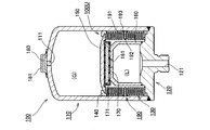
- FIG. 10 shows a sixth embodiment of the present invention.
- a metal bellows was comprised by a single component
- this Example the case where a metal bellows is comprised by several components is shown. Since other configurations and operations are the same as those in the first embodiment, the same components are denoted by the same reference numerals and description thereof is omitted.
- FIG. 10 is a schematic cross-sectional view of an accumulator according to Example 6 of the present invention, showing a state in which the metal bellows is extended.
- the metal bellows 130 When the metal bellows 130 is long in the axial direction, it may be difficult to form the metal bellows 130 as a single part due to molding and dimensional accuracy.
- the damping member 190 it may be difficult to provide the trough part 131b according to the shape and dimension of the damping member 190 in the metal bellows 130 comprised by a single component. Therefore, the metal bellows 130 according to the present embodiment employs a configuration in which a dedicated valley forming member 130Y for attaching the vibration damping member 190 is provided between the pair of metal bellows main bodies 130X.
- the vibration damping member 190X shown in the second embodiment can be employed.
- the structure which attaches the damping member 190 to several places is also employable by using 3 or more metal bellows main bodies 130X and using 2 or more valley formation members 130Y. In this case, it is also possible to employ a configuration that does not use a sliding ring as in the case of the fifth embodiment.
- the metal bellows used in the accumulator of the present invention is not limited to the molded bellows.
- a welding bellows obtained by welding a plurality of metal thin annular members can be employed.
- the external gas type accumulator configured such that the outside of the metal bellows 130 is the gas chamber (G) has been described as an example.
- the present invention is not limited to an outer gas type accumulator, and can also be applied to an inner gas type accumulator configured such that the inside of the metal bellows is a gas chamber. Note that the internal gas type accumulator is disclosed in FIG.
Landscapes
- Engineering & Computer Science (AREA)
- General Engineering & Computer Science (AREA)
- Mechanical Engineering (AREA)
- Physics & Mathematics (AREA)
- Fluid Mechanics (AREA)
- Supply Devices, Intensifiers, Converters, And Telemotors (AREA)
- Diaphragms And Bellows (AREA)
Abstract
Description
圧力容器と、
該圧力容器内に設けられ、ガスが密封されたガス室と、作動流体が流れる流体室とに仕切る仕切りユニットと、
を備え、
前記仕切りユニットは、ガス室内の圧力と流体室内の圧力とに応じて伸縮する金属ベローズを備えており、
複数の環状の山部と複数の環状の谷部が交互に形成された前記金属ベローズにおける複数の環状の谷部のうちの少なくとも1箇所に、前記圧力容器の内周面に摺動自在に構成され、前記金属ベローズと前記圧力容器の内周面との間の隙間を維持させつつ前記金属ベローズの振動を抑制する制振部材が装着されるアキュムレータであって、
前記制振部材は、径方向の内側の先端が前記谷部に対して嵌合され、径方向外側の先端が前記金属ベローズの山部よりも径方向外側に長いことを特徴とする。
周方向に伸びる胴体部と、
該胴体部の径方向内側に設けられ、前記谷部に対して嵌合される被嵌合部と、
を備えており、
前記金属ベローズの伸縮状態に関係なく、前記金属ベローズと前記胴体部との間に隙間が形成されるように、前記制振部材は前記金属ベローズに位置決め固定されているとよい。
前記ガイド部の厚みは、前記金属ベローズの伸縮状態に関係なく、前記金属ベローズの山部の先端に接触しない厚さに設定されているとよい。
これにより、ガイド部を設けた場合でも、制振部材が圧力容器の内周面から衝撃を受けた際に、金属ベローズの山部に衝撃が伝わってしまうことを抑制することができる。
図1~図5を参照して、本発明の実施例1に係るアキュムレータについて説明する。図1及び図2は本発明の実施例1に係るアキュムレータの模式的断面図であり、図1は金属ベローズが伸びた状態を示し、図2は金属ベローズが縮んだ状態を示している。図3は本発明の実施例1に係るアキュムレータの模式的断面図の一部拡大図であり、制振部材が装着されている付近を拡大した断面図である。図4は本発明の実施例1に係る制振部材の平面図である。図5は本発明の実施例1に係る制振部材の側面図であり、制振部材を外周面側から見た図である。
特に、図1及び図2を参照して、本発明の実施例1に係るアキュムレータの全体構成について説明する。本実施例に係るアキュムレータ100は、多量のエネルギーを短時間に放出させたり、圧力変動の緩和などを行うために用いることができる。より具体的な例としては、自動車における油が流れる配管内の脈動を緩和させるために用いることができる。また、本実施例に係るアキュムレータ100は、中心軸線に対して回転対称形状である。
特に、図3~図5を参照して、制振部材190について詳細に説明する。制振部材190は、圧力容器110の内周面に摺動自在に構成されている。また、制振部材190は、金属ベローズ130と圧力容器110の内周面との間の隙間を維持させつつ金属ベローズ130の振動を抑制する役割を担っている。本実施例に係る制振部材190は、径方向の内側の先端が金属ベローズ130における谷部131bに対して嵌合されるように構成されている。より具体的には、本実施例に係る制振部材190は、周方向に伸びる胴体部191と、胴体部191の径方向内側に設けられ、金属ベローズ130における谷部131bに対して嵌合される被嵌合部192とを備えている。また、本実施例に係る制振部材190においては、胴体部191における径方向外側に、金属ベローズ130における伸縮方向(軸線方向に等しい)の幅が胴体部191における当該幅よりも広いガイド部193が設けられている。このガイド部193は、胴体部191の移動を案内する役割を担っており、胴体部191における径方向外側に、周方向に間隔を空けて複数設けられている。なお、本実施例では、5か所にガイド部193が設けられているが、ガイド部193の個数は適宜設定することができる。また、ガイド部193及び胴体部191のうちガイド部193が設けられていない部分の外周面は、圧力容器110の内周面との間に僅かに隙間が形成されるように設計されている(図3参照)。尚、この形状に限らず、胴体部191やガイド部193に、圧力容器110の内部の流体を流通させる貫通孔を設けていてもよい。また、胴体部191やガイド部193の外周面に圧力容器110の内部の流体を流通させる溝を設けていてもよい。
本実施例に係るアキュムレータ100によれば、制振部材190によって、金属ベローズ130が圧力容器110の内周面に直接突き当たることを抑制でき、かつ金属ベローズ130の振動を抑制させることができる。また、制振部材190は、径方向の内側の先端(被嵌合部192)が金属ベローズ130における谷部131bに対して嵌合されている。これにより、制振部材190は、金属ベローズ130の山部131aの先端から離れた状態で位置決め固定されている。そのため、制振部材190が圧力容器110の内周面から衝撃を受けた場合でも、金属ベローズ130の山部131aに衝撃が伝わってしまうことを抑制することができる。ここで、制振部材190が圧力容器110の内周面から衝撃を受けた場合には、金属ベローズ130における谷部131bに衝撃が伝わるものの、制振部材190全体を通して衝撃が伝わる。つまり、圧力容器110の内周面からの衝撃は、ガイド部193から胴体部191及び被嵌合部192を通って金属ベローズ130における谷部131bに伝わる。これにより、制振部材190全体により衝撃が緩和される。従って、従来例のように、中間リング590のガイド部592から山部に衝撃が伝わる場合に比べて、衝撃を十分に緩和させることができる。以上のように、制振部材190によって、金属ベローズ130への衝撃が緩和されるので、金属ベローズ130が変形したり、破損したりすることを抑制することができる。
図6には、本発明の実施例2が示されている。本実施例においては、制振部材の構造が、実施例1とは異なる場合の構成を示す。その他の構成および作用については実施例1と同一なので、同一の構成部分については同一の符号を付して、その説明は省略する。
図7には、本発明の実施例3が示されている。本実施例においては、制振部材の取り付け位置が、実施例1とは異なる場合の構成を示す。その他の構成および作用については実施例1と同一なので、同一の構成部分については同一の符号を付して、その説明は省略する。
図8には、本発明の実施例4が示されている。本実施例においては、制振部材の取り付け箇所を2か所にした場合の構成を示す。その他の構成および作用については実施例1と同一なので、同一の構成部分については同一の符号を付して、その説明は省略する。
図9には、本発明の実施例5が示されている。本実施例においては、制振部材の取り付け箇所を2か所にした上で、実施例1で示した摺動リングを用いない場合の構成を示す。その他の構成および作用については実施例1と同一なので、同一の構成部分については同一の符号を付して、その説明は省略する。
図10には、本発明の実施例6が示されている。上記実施例1においては、金属ベローズが単一部品により構成される場合を示したが、本実施例においては、金属ベローズが複数の部品により構成される場合を示す。その他の構成および作用については実施例1と同一なので、同一の構成部分については同一の符号を付して、その説明は省略する。
上記各実施例においては、金属ベローズ130として、成形ベローズを採用する場合を示した。しかしながら、本発明のアキュムレータに用いられる金属ベローズは、成形ベローズに限られることはない。例えば、複数の金属製の薄板円環状の部材を溶接することにより得られる溶接ベローズを採用することもできる。
100U 仕切りユニット
110 圧力容器
111 貫通孔
120 ポート形成部材
121 ポート
130 金属ベローズ
130X 金属ベローズ本体
130Y 谷部形成部材
131a 山部
131b 谷部
131c 腹部
140 摺動リング
150 ベローズキャップ
160 略有底円筒状部材
161 貫通孔
170 シール部材
171 シールホルダ
180 プラグ
181 プラグガイド
190,190X 制振部材
191 胴体部
192 被嵌合部
193 ガイド部
194 外周面
C 切断部
S 隙間
Claims (4)
- 圧力容器と、
該圧力容器内に設けられ、ガスが密封されたガス室と、作動流体が流れる流体室とに仕切る仕切りユニットと、
を備え、
前記仕切りユニットは、ガス室内の圧力と流体室内の圧力とに応じて伸縮する金属ベローズを備えており、
複数の環状の山部と複数の環状の谷部が交互に形成された前記金属ベローズにおける複数の環状の谷部のうちの少なくとも1箇所に、前記圧力容器の内周面に摺動自在に構成され、前記金属ベローズと前記圧力容器の内周面との間の隙間を維持させつつ前記金属ベローズの振動を抑制する制振部材が装着されるアキュムレータであって、
前記制振部材は、径方向の内側の先端が前記谷部に対して嵌合され、径方向外側の先端が前記金属ベローズの山部よりも径方向外側に長いことを特徴とするアキュムレータ。 - 前記制振部材は、
周方向に伸びる胴体部と、
該胴体部の径方向内側に設けられ、前記谷部に対して嵌合される被嵌合部と、
を備えており、
前記金属ベローズの伸縮状態に関係なく、前記金属ベローズと前記胴体部との間に隙間が形成されるように、前記制振部材は前記金属ベローズに位置決め固定されていることを特徴とする請求項1に記載のアキュムレータ。 - 前記胴体部における径方向外側には、前記金属ベローズにおける伸縮方向の幅が前記胴体部の該幅よりも広く、該胴体部の移動を案内するガイド部が周方向に間隔を空けて複数設けられていることを特徴とする請求項2に記載のアキュムレータ。
- 前記ガイド部の厚みは、前記金属ベローズの伸縮状態に関係なく、前記金属ベローズの山部の先端に接触しない厚さに設定されていることを特徴とする請求項3に記載のアキュムレータ。
Priority Applications (4)
| Application Number | Priority Date | Filing Date | Title |
|---|---|---|---|
| EP16772714.8A EP3279481B1 (en) | 2015-04-02 | 2016-03-28 | Accumulator |
| JP2017509959A JP6657188B2 (ja) | 2015-04-02 | 2016-03-28 | アキュムレータ |
| US15/563,432 US10273979B2 (en) | 2015-04-02 | 2016-03-28 | Accumulator |
| CN201680018945.3A CN107407297B (zh) | 2015-04-02 | 2016-03-28 | 蓄能器 |
Applications Claiming Priority (2)
| Application Number | Priority Date | Filing Date | Title |
|---|---|---|---|
| JP2015-076279 | 2015-04-02 | ||
| JP2015076279 | 2015-04-02 |
Publications (1)
| Publication Number | Publication Date |
|---|---|
| WO2016158833A1 true WO2016158833A1 (ja) | 2016-10-06 |
Family
ID=57007097
Family Applications (1)
| Application Number | Title | Priority Date | Filing Date |
|---|---|---|---|
| PCT/JP2016/059849 Ceased WO2016158833A1 (ja) | 2015-04-02 | 2016-03-28 | アキュムレータ |
Country Status (5)
| Country | Link |
|---|---|
| US (1) | US10273979B2 (ja) |
| EP (1) | EP3279481B1 (ja) |
| JP (1) | JP6657188B2 (ja) |
| CN (1) | CN107407297B (ja) |
| WO (1) | WO2016158833A1 (ja) |
Families Citing this family (6)
| Publication number | Priority date | Publication date | Assignee | Title |
|---|---|---|---|---|
| EP3306108B1 (en) * | 2015-05-29 | 2020-05-06 | Eagle Industry Co., Ltd. | Metal bellows-type accumulator |
| CN109505809A (zh) * | 2018-12-28 | 2019-03-22 | 中国航空工业集团公司西安飞行自动控制研究所 | 一种波纹管蓄能器的耐压壳体结构 |
| CN112112845B (zh) * | 2020-10-10 | 2022-06-28 | 浙江奥莱尔液压有限公司 | 一种胶囊储能器 |
| US11761507B2 (en) * | 2021-02-10 | 2023-09-19 | DRiV Automotive Inc. | Weight optimized bellow accumulator |
| US20220375630A1 (en) * | 2021-05-24 | 2022-11-24 | Commonwealth Fusion Systems Llc | Tritium injection techniques and related systems and methods |
| CN119022165A (zh) * | 2024-10-28 | 2024-11-26 | 三峡金沙江川云水电开发有限公司 | 一种电气自动化控制阀门装置 |
Citations (3)
| Publication number | Priority date | Publication date | Assignee | Title |
|---|---|---|---|---|
| JPH02113139A (ja) * | 1988-10-20 | 1990-04-25 | Nhk Spring Co Ltd | アキュムレータ |
| JPH11117901A (ja) * | 1997-10-09 | 1999-04-27 | Ishikawajima Harima Heavy Ind Co Ltd | アキュムレータ |
| JP2012167748A (ja) * | 2011-02-15 | 2012-09-06 | Nok Corp | アキュムレータ |
Family Cites Families (14)
| Publication number | Priority date | Publication date | Assignee | Title |
|---|---|---|---|---|
| US2731037A (en) | 1950-09-23 | 1956-01-17 | Chicago Metal Hose Corp | Hydraulic accumulators |
| JP2539905B2 (ja) * | 1989-01-20 | 1996-10-02 | 日本発条株式会社 | アキュムレ―タ |
| JP2858807B2 (ja) * | 1989-08-30 | 1999-02-17 | 日本発条株式会社 | アキュムレータおよびこのアキュムレータの製造方法 |
| JPH05172101A (ja) * | 1991-12-20 | 1993-07-09 | Tokico Ltd | アキュムレータ |
| JP3812621B2 (ja) * | 1998-10-15 | 2006-08-23 | Nok株式会社 | 端面シール |
| DE19852628B4 (de) * | 1998-11-14 | 2005-09-15 | Integral Accumulator Kg | Hydrospeicher mit einem Metallfaltenbalg als Trennwand |
| US6478051B1 (en) * | 1998-11-25 | 2002-11-12 | Continental Teves Ag & Co., Ohg | Pressure means storage device |
| JP2000352497A (ja) * | 1999-06-11 | 2000-12-19 | Nok Corp | 圧力容器の気体封入方法 |
| JP2001012401A (ja) | 1999-07-02 | 2001-01-16 | Nok Corp | 圧力容器の製造方法 |
| DE10003648A1 (de) * | 2000-01-29 | 2001-08-09 | Hydac Technology Gmbh | Hydropneumatischer Druckspeicher |
| JP2002276604A (ja) * | 2000-08-09 | 2002-09-25 | Nok Corp | アキュムレータ |
| JP4735811B2 (ja) | 2005-04-15 | 2011-07-27 | Nok株式会社 | アキュムレータ |
| JP3113825U (ja) * | 2005-06-17 | 2005-09-22 | Nok株式会社 | アキュムレータ |
| CN200993129Y (zh) * | 2006-11-23 | 2007-12-19 | 王祖林 | 一种组合壳体的隔膜式蓄能器 |
-
2016
- 2016-03-28 JP JP2017509959A patent/JP6657188B2/ja active Active
- 2016-03-28 WO PCT/JP2016/059849 patent/WO2016158833A1/ja not_active Ceased
- 2016-03-28 EP EP16772714.8A patent/EP3279481B1/en active Active
- 2016-03-28 CN CN201680018945.3A patent/CN107407297B/zh active Active
- 2016-03-28 US US15/563,432 patent/US10273979B2/en active Active
Patent Citations (3)
| Publication number | Priority date | Publication date | Assignee | Title |
|---|---|---|---|---|
| JPH02113139A (ja) * | 1988-10-20 | 1990-04-25 | Nhk Spring Co Ltd | アキュムレータ |
| JPH11117901A (ja) * | 1997-10-09 | 1999-04-27 | Ishikawajima Harima Heavy Ind Co Ltd | アキュムレータ |
| JP2012167748A (ja) * | 2011-02-15 | 2012-09-06 | Nok Corp | アキュムレータ |
Also Published As
| Publication number | Publication date |
|---|---|
| US20180066679A1 (en) | 2018-03-08 |
| CN107407297A (zh) | 2017-11-28 |
| EP3279481B1 (en) | 2020-06-10 |
| EP3279481A1 (en) | 2018-02-07 |
| EP3279481A4 (en) | 2018-11-07 |
| US10273979B2 (en) | 2019-04-30 |
| CN107407297B (zh) | 2019-09-06 |
| JPWO2016158833A1 (ja) | 2018-02-01 |
| JP6657188B2 (ja) | 2020-03-04 |
Similar Documents
| Publication | Publication Date | Title |
|---|---|---|
| WO2016158833A1 (ja) | アキュムレータ | |
| JP6760954B2 (ja) | アキュムレータ | |
| JP6351746B2 (ja) | 緩衝器 | |
| CN105317906B (zh) | 缓冲器 | |
| CN109642675B (zh) | 密封装置 | |
| JP5825431B2 (ja) | バッファリング | |
| EP2884121B1 (en) | Ball joint dust cover | |
| US20180128288A1 (en) | Accumulator | |
| JP2019138354A5 (ja) | ||
| US10330170B2 (en) | Shock absorber | |
| US20240052906A1 (en) | Vibration damper for a vehicle | |
| US10907657B2 (en) | Accumulator | |
| JP5434681B2 (ja) | ガスケット及び密封構造 | |
| JP2016020721A (ja) | 密封装置 | |
| JP6123953B2 (ja) | 吸気音低減装置 | |
| JP7274363B2 (ja) | 密封構造 | |
| KR101712663B1 (ko) | 기밀을 유지하기 위한 오일홈 구조 | |
| JP6361397B2 (ja) | 吸気音低減装置 | |
| JP6350087B2 (ja) | 吸気音低減装置 | |
| JP6365806B1 (ja) | ダストシール | |
| JP2010101426A (ja) | 密封装置 | |
| JP2019078287A (ja) | シールリング | |
| JP2016037864A (ja) | 吸気音低減装置 | |
| JP2009138882A (ja) | 金属ベローズ式アキュムレータ | |
| JP2020012514A (ja) | 管状体の接続構造 |
Legal Events
| Date | Code | Title | Description |
|---|---|---|---|
| 121 | Ep: the epo has been informed by wipo that ep was designated in this application |
Ref document number: 16772714 Country of ref document: EP Kind code of ref document: A1 |
|
| ENP | Entry into the national phase |
Ref document number: 2017509959 Country of ref document: JP Kind code of ref document: A |
|
| WWE | Wipo information: entry into national phase |
Ref document number: 15563432 Country of ref document: US |
|
| NENP | Non-entry into the national phase |
Ref country code: DE |
|
| REEP | Request for entry into the european phase |
Ref document number: 2016772714 Country of ref document: EP |