WO2016159397A1 - Dispositif d'affichage d'image stéréoscopique à multiples couches - Google Patents
Dispositif d'affichage d'image stéréoscopique à multiples couches Download PDFInfo
- Publication number
- WO2016159397A1 WO2016159397A1 PCT/KR2015/003082 KR2015003082W WO2016159397A1 WO 2016159397 A1 WO2016159397 A1 WO 2016159397A1 KR 2015003082 W KR2015003082 W KR 2015003082W WO 2016159397 A1 WO2016159397 A1 WO 2016159397A1
- Authority
- WO
- WIPO (PCT)
- Prior art keywords
- screen
- image
- slit
- unit
- slit member
- Prior art date
- Legal status (The legal status is an assumption and is not a legal conclusion. Google has not performed a legal analysis and makes no representation as to the accuracy of the status listed.)
- Ceased
Links
Images



Classifications
-
- H—ELECTRICITY
- H04—ELECTRIC COMMUNICATION TECHNIQUE
- H04N—PICTORIAL COMMUNICATION, e.g. TELEVISION
- H04N13/00—Stereoscopic video systems; Multi-view video systems; Details thereof
- H04N13/30—Image reproducers
Definitions
- the present invention relates to a multi-layer stereoscopic image display apparatus, and more particularly, it is possible to compositely display a sense of space and a sense of spatial separation from a depth and a stereoscopic image from two-dimensional and three-dimensional image data.
- the present invention relates to a multilayer autostereoscopic 3D display device capable of suppressing moiré phenomenon.
- 3D image processing technology has been used in a variety of fields, such as education, training, medicine, film, computer games.
- the 3D image is more efficient than the 2D image to feel presence, real feeling, and natural feeling.
- Such a 3D image display device requires various technologies such as input technology, processing technology, transmission technology, display technology, software technology, and the like, and especially for a human visual system such as display technology, digital image processing technology, computer graphics technology, and the like. Research is essential.
- the most well-known method of the display method of the three-dimensional image display device is the integral photography method, which records three-dimensional images formed by a microlens array shaped like a fly's eye. And transmission and reproduction.
- the three-dimensional image display apparatus arranges a microlensarray 1 having the fly-eye microlenses 2, and the microlens array 1 Place an aspect carrier 3 with individual pixels 4 at regular intervals from.
- the above-described integral photography method has a problem in that image quality deterioration of a 3D image due to a moire ⁇ effect occurs.
- the moiré effect is a phenomenon in which periodic patterns cause wave patterns while interfering with each other.
- a display structure including a multilayer image and a stereoscopic image and a space between the depth and the spatial space of a depth from a 2D image and a 3D image data to a depth and a 3D image when displayed on a device
- a multi-layer stereoscopic image display apparatus which can display a feeling of separation in complex, and can further suppress the occurrence of moiré phenomenon.
- an embodiment of the present invention provides a multi-dimensional stereoscopic image display apparatus which selectively combines multiple screens that are transparent and maintain a certain distance and overlap.
- an embodiment of the present invention provides a multi-dimensional stereoscopic image display apparatus in which the image observed on each screen may be an autostereoscopic display or a transparent display.
- an embodiment of the present invention uses an autostereoscopic 3D image method while selectively using a normal compression algorithm, a 3D image of a binocular disparity method, and a 3D image algorithm of an N parallax method to display images individually on a superimposed display.
- a normal compression algorithm e.g., a 3D image of a binocular disparity method
- a 3D image algorithm of an N parallax method e.
- Multi-layer stereoscopic image display apparatus includes a first screen for displaying a first image including a left eye image and a right eye image; A second screen disposed to be spaced apart from the first screen to display a second image; And a slit member attached to the first screen facing the second screen and formed in an oblique shape to emit the left eye image and the right eye image to the left and right eyes of a user located in front of the second screen.
- a slit member attached to the first screen facing the second screen and formed in an oblique shape to emit the left eye image and the right eye image to the left and right eyes of a user located in front of the second screen.
- the second screen is not spaced apart from the first screen, but is arranged in close contact, and between the second screen and the slit member, a polarization retardation plate for adjusting the linear polarization angle of the first screen and the second screen, or anti-reflection A film may be provided.
- the slit member may be arranged such that the first unit slit facing the left eye of the user and the second unit slit facing the right eye are alternated with each other.
- the slit member may include a plurality of unit slits, and the unit slit may include a first unit slit facing the user's left eye and a second unit slit disposed alternately with the first unit slit facing the user's right eye. Can be.
- the slit member may include a plurality of unit slits, and the unit slits may have an inclination angle of 30 degrees to 60 degrees with respect to a reference plane, and the reference plane may be defined as a ground on which the user is located.
- the slit member may include a plurality of unit slits, and the unit slits may have an embossed shape convex in the second screen direction.
- the slit member may be provided with any one of acrylic, glass, and a polarization retardation plate or film for adjusting the linear polarization angle of the first screen and the second screen.
- the first screen may display a two-dimensional image or a three-dimensional image
- the second screen may display a two-dimensional image, but may be an optionally transparent screen.
- a light source for emitting light to the second screen may be disposed between the second screen and the first screen.
- the multi-layer stereoscopic image display apparatus includes a first screen for displaying a first image including a left eye image and a right eye image; A second screen disposed to be spaced apart from the first screen to display a second image; And a slit member attached to the first screen and formed in a predetermined pattern to emit the left eye image and the right eye image to the left and right eyes of the user located in front of the second screen.
- the predetermined pattern may be any one of a plaid pattern, a plaid pattern, an inclined plaid pattern, and an inclined plaid pattern that divides the slit member at regular intervals in the longitudinal and transverse directions.
- the predetermined pattern may include a plurality of unit slits having the same shape, and the unit slits may have an embossed shape convex toward the second screen.
- the multilayer stereoscopic image display apparatus can not only prevent a moire effect, but also improve clarity and brightness.
- one embodiment of the present invention can make the implementation of colors more realistic and clear.
- FIG. 1 is a view showing a three-dimensional image display apparatus according to the prior art.
- FIG. 2 is a perspective view of a multi-layer stereoscopic image display apparatus according to an embodiment of the present invention.
- FIG. 3 is an exploded perspective view of the multilayer stereoscopic image display apparatus of FIG. 2.
- FIG. 4 is a view illustrating the slit member of FIG. 2.
- FIG. 5 is a diagram illustrating a modified example of the slit member of FIG. 2.
- FIG. 6 and 7 are views illustrating an operation of the multilayer stereoscopic image display apparatus of FIG. 2.
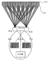
- FIG. 8 is a diagram illustrating a state of use of the multilayer stereoscopic image display apparatus of FIG. 2.
- FIG. 2 is a diagram illustrating a multilayer stereoscopic image display apparatus according to an embodiment of the present invention
- FIG. 3 is an exploded perspective view of the multilayer stereoscopic image display apparatus of FIG. 2
- FIG. 4 is a diagram illustrating the slit member of FIG. 2
- 5 is a diagram illustrating a modified example of the slit member of FIG. 2
- FIGS. 6 and 7 are views illustrating an operation of the multilayer stereoscopic image display apparatus of FIG. 2
- FIG. 8 is a state of use of the multilayer stereoscopic image display apparatus of FIG. 2. It is a figure which shows.
- a multi-dimensional stereoscopic image display apparatus 100 may have various information and / or images through two overlapping first screens 102 and second screens 104.
- the device to be displayed includes a first screen 102, a second screen 104, a slit member 108 and a polarization retardation plate 106.
- the multi-layer stereoscopic image display apparatus 100 may include a slit member attached on the first screen 102 between the first screen 102 and the second screen 104. 108, and a polarization retardation plate 106 selectively inserted between the first screen 102 and the second screen 104, wherein the first screen 102 and the second screen 104 are at least partially. Nested.
- the first screen 102 and the second screen 104 are arranged to selectively overlap, and one or more screens are arranged horizontally and checkered on one side of the transparent display.
- the first screen 102 is a panel displaying a first image including a left eye image and a right eye image, and may be implemented as various color LCD liquid crystals.
- the first screen 102 may alternately display the left eye image and the right eye image.
- the first screen 102 may display a two-dimensional image or a three-dimensional image according to whether the light emitted from the front and rear or side is divided into left eye or right eye.
- the second screen 104 is a panel that is positioned at a predetermined distance from the first screen 102 to display the second image, and may be implemented as a transparent LCD liquid crystal.
- the second screen 104 may display a two-dimensional image.
- the second screen 104 may be spaced apart from the first screen 102 by about 2 cm to 4 cm, but may be spaced at intervals of 3 cm.
- the second screen 104 may display a two-dimensional image.
- the multi-layered autostereoscopic 3D display device 100 is arranged so that the first screen 102 and the second screen 104 are separated by a predetermined distance, thereby physically overlapping the first image and the second image.
- the 3D image effect may be implemented, and thus, a congestion phenomenon felt by the user may be prevented.
- the second screen 104 may be disposed to be in close contact with each other without being spaced apart from the first screen 102. Accordingly, the second screen 104 may be formed almost integrally with the polarization retardation plate 106 disposed between the slit member 108 attached on the first screen 102. In addition, an antireflection film (not shown) may be disposed between the second screen 104 and the slit member 108 or the first screen 102 that are in close contact with each other.
- the second screen 104 and the first screen 102 are in close contact with each other, and the moiré effect due to color interference that may occur due to the distance between the second screen 104 and the first screen 102. Can be significantly reduced.
- LCD liquid crystal is a device that displays by using the property of liquid crystal that changes the arrangement of molecules when voltage is applied, and arranges by injecting liquid crystal into the narrow gap between two glass plates and applying electric pressure through transparent electrodes to each liquid crystal molecule.
- first screen 102 and the second screen 104 are data or data formats that visually represent characters, symbols, plain text, images, still and moving animations, still and moving video footage, and combinations and information thereof. It includes.
- the first screen 102 and the second screen 104 place closed polarization filters on the front and back of each liquid crystal active element.
- the planar polarization of the light coming from the front of the second screen 104 intersects with respect to the polarization plane behind the first screen 102.
- the polarization between the first screen 102 and the second screen 104 in order to rotate the light from the second screen 104 to the required angle to align with the rear polarizing filter of the first screen 102
- the delay plate 106 is provided.
- the polarization retardation plate 106 causes a phase angle variation or delay less than or equal to the incident light wavelength. In addition, the polarization retardation plate 106 does not produce vivid color interference fringes when used in the present multilayer stereoscopic image display apparatus 100.
- the polarization retardation plate 106 has had disadvantages such as unstable exposure to bright light and / or discoloration, manufacturing cost, and brittleness over time, but in the present invention, in order to compensate for such disadvantages, the optical properties of the biaxial polypropylene It consists of a material with properties.
- the biaxial polypropylene may be made of a transparent and flexible film, but the present invention does not limit the type of biaxial polypropylene, but may be made of a lacquer or a coating.
- the polarization retardation plate 106 can be placed anywhere between the first screen 102 and the second screen 104, but the polarization retardation plate 106 of a technology such as polyester allows the second screen ( It is preferable to install on the back of 104). This is to avoid the interference that the diffusion pattern to be applied to the polarization retardation plate 106 deteriorates the image of the multilayer stereoscopic image display apparatus 100.
- the interference pattern is generated due to the moire effect, which is the interference due to the minute temporal mismatch between the structural surfaces of the first screen 102 and the second screen 104, and the effect that the white polarization is separated into rainbow colors.
- the diffusion of light is used to eliminate the interference pattern generated between the first screen 102 and the second screen 104.
- the slit member 108 is composed of a layer separate from the polarization retardation plate 106, and is formed in a pattern having a shape of embossing of a constant length in diagonal lines or of a shape of a check and a line.
- the slit member 108 may distinguish the pixels visible to the left eye and the right eye differently, and apply an image to be received differently, thereby making it possible to feel a three-dimensional effect by binocular disparity without wearing glasses.
- the slit member 108 is preferably installed at the front of the first screen 102, it is made of an embossed form of a constant length diagonally.
- the slit member 108 may include a slit division method including a parallax barrier method, a lenticular method, or a tracking method time division method so as to optically distinguish the left image from the right image on the first screen 102 that is selectively overlapped. Can be distinguished by.
- the slit member 108 includes a plurality of unit slits 108a and 108b.
- the unit slits 108a and 108b are arranged such that the unit slits facing the left eye of the user and the unit slits facing the right eye are alternated with each other.
- the unit slits 108a and 108b may include a first unit slit 108a facing the user's left eye and a second unit slit 108b disposed alternately with the first unit slit 108a facing the user's right eye. It may include. That is, the unit slits 108a and 108b may include first unit slits, second unit slits, and n-th unit slits that are alternated with each other.
- the unit slits 108a and 108b are diagonally formed to have an inclination angle ⁇ of 5 degrees to 85 degrees with respect to the reference plane.
- the unit slits 108a and 108b have an inclination angle ⁇ of 5 degrees or less with respect to the reference plane, or have an inclination angle ⁇ of 85 degrees or more with respect to the reference plane, they are closer to a vertical or horizontal type than to the diagonal.
- the conventional stereoscopic display apparatus there is a problem that it is difficult to secure the viewing angle.
- the reference plane may be defined as the ground on which the user is located.
- the unit slits 108a and 108b are formed to have an embossed shape that is convex forward in the direction of the second screen 104.
- the unit slits 208a and 208b may be formed in a lattice pattern or a checker pattern partitioning at regular intervals in the longitudinal and transverse directions, as shown in FIG. It may be formed as an inclined checkered pattern.
- the material of the slit member 108 may be in the form of acrylic, glass, LCD, optical retardation plate, film, each of which may be composed of a single and complex in a uniform form.
- the slit member 108 is adhered to the front of the first screen 102, the adhesive method to determine a predetermined thickness and form a gap physically, the front surface or a plurality of partial surfaces of the UV liquid curing method, It can be bonded by an adhesive method through an adhesive that has a predetermined thickness such as a slope.
- the slit member 108 alternates the red, green, and blue subpixels in the row direction with each other, as shown in FIGS. 6 to 8, to display content divided into parallax of both eyes and N parallax.
- a stereoscopic image such as a left eye L, a right eye R, or an N eye, is disposed on the flat panel display arranged in the above, and is physically attached to the flat panel display.
- the slit member 108 is a physical optically configured filter that allows only the right eye image in the right eye and the left eye image in the left eye, so that the viewer's eyes can display different images so that a 3D feeling can be felt.
- the phase difference of the polarization retardation plate 106 is less than or equal to 560 nm. Therefore, according to the present invention, the polarization retardation plate 106 produces a phase angle delay that is less than or equal to one wavelength of light incident on the multilayer stereoscopic image display apparatus 100. This is also referred to as a linear displacement less than or equal to 560 nm of incident light.
- the multilayer stereoscopic image display apparatus 100 may further include a third screen (not shown).
- the third screen is located behind the first screen 102 and at least a portion of the third screen overlaps the first screen 102 and the second screen 104 and generates a stereoscopic image display and a normal (2D) image display. .
- divergence of the light source can optionally be obtained from the polarization source for the display of the first image on the first screen 102, and additionally between the first screen 102 and the second screen 104 or the like. Illustration is omitted).
- the multilayer autostereoscopic 3D display device 100 includes all of the processing speed, color, repetition, visual effect, ruming, scrolling, flicker fading and size improvement and change, and optionally on a superimposed screen. It includes vertically constant plate, horizontally constant plate, obliquely constant plate, mosaic pattern, color difference classification, and time difference classification method, and synthesizes the method up to N parallax including Side by Side method. It is possible to generate and display the change of the stereoscopic (3D) image from the normal (2D) image.
- an edge member made of a polypropylene resin composition may be provided at the edge portion of the first screen 102 to improve impact resistance and rigidity of the edge portion of the first screen 102.
- the polypropylene resin composition is a polypropylene impact copolymer composition comprising a polypropylene homopolymer and an ethylene-propylene block copolymer.
- the polymers are resins mixed in the polymerization step.
- the polypropylene homopolymer maintains the mechanical rigidity of the polypropylene resin composition while imparting an appropriate degree of heat resistance.
- the polypropylene homopolymer may be included in 70 to 95% by weight relative to the total weight of the polypropylene impact copolymer. If the content of the polypropylene homopolymer is less than 70% by weight, the stiffness of the final polypropylene resin composition is lowered to satisfy the required properties of the final product, and if the content of the polypropylene homopolymer exceeds 95% by weight, the content of the ethylene-propylene block copolymer is polymerized. This low difficulty in expressing the impact resistance characteristics.
- the ethylene-propylene block copolymer is prepared by continuously polymerizing in a series of reactors after the production of polypropylene homopolymer, the ethylene-propylene block copolymer of the present invention serves to impart impact resistance to the polypropylene resin composition Do it.
- the content of the ethylene-propylene block copolymer based on the total weight of the polypropylene impact copolymer may be 5 to 30% by weight. If the content of the ethylene-propylene block copolymer is less than 5% by weight, the impact resistance is not expressed, and if the content of the ethylene-propylene block copolymer is more than 30% by weight, the rigidity is lowered, thereby making it difficult to satisfy the final required characteristics of the product.
- the ethylene content of the total weight of the ethylene-propylene block copolymer is 30 to 70% by weight, preferably 40 to 60% by weight.
- the impact-resistant amorphous portion is reduced in the block copolymer to be polymerized, and the impact resistance is reduced.
- the content is greater than 70% by weight, the crystalline polyethylene component is polymerized to be continuous. The compatibility with the phases may be reduced, thereby reducing the impact resistance characteristics due to interfacial peeling upon impact.
- the ethylene-propylene block copolymer may have an intrinsic viscosity (Intrinsic Viscosity, dl / g) of 3 to 8dl / g. At this time, the intrinsic viscosity was measured using a viscosity meter for the ethylene-propylene block copolymer extracted in 135 °C, decalin solution for 4g polypropylene impact copolymer. When the intrinsic viscosity is less than 3, the molecular weight of the polymerized ethylene-propylene block copolymer is low, which makes it difficult to absorb shock.
- intrinsic Viscosity Intrinsic Viscosity, dl / g
- the polypropylene impact copolymer is characterized in that the weight average molecular weight (Mw) is 250,000 to 2,000,000. If the weight average molecular weight is less than 250,000, the molecular weight is low, the rigidity is lowered, there is a difficulty in absorbing shock, and if it exceeds 2000,000, it is difficult to polymerize in the reactor.
- Mw weight average molecular weight
Landscapes
- Engineering & Computer Science (AREA)
- Multimedia (AREA)
- Signal Processing (AREA)
- Testing, Inspecting, Measuring Of Stereoscopic Televisions And Televisions (AREA)
Abstract
La présente invention concerne, selon un mode de réalisation, un dispositif d'affichage d'image stéréoscopique à multiples couches. Pour parvenir à un objectif technique, une solution consiste à afficher de manière complexe une sensation de la distance de profondeur et une sensation de la distance spatiale au moyen d'une image de profondeur et stéréoscopique à partir de données vidéo en 2D et en 3D lors de l'affichage sur un dispositif d'une structure d'affichage comprenant une image à multiples couches et une image stéréoscopique et à empêcher également les effets de moiré. A cet effet, la présente invention se rapporte à dispositif d'affichage d'image stéréoscopique à multiples couches comprenant : un premier écran qui est destiné à afficher une première image comprenant une image d'œil gauche et une image d'œil droit; un second écran qui est disposé à l'opposé du premier écran et est destiné à afficher une seconde image; et un élément à fente qui est collé sur le premier écran faisant face au second écran, qui est formé de manière oblique, et qui est destiné à projeter l'image d'œil gauche et l'image d'œil droit à l'œil gauche et à l'œil droit d'un utilisateur qui se trouve devant le second écran.
Priority Applications (1)
| Application Number | Priority Date | Filing Date | Title |
|---|---|---|---|
| PCT/KR2015/003082 WO2016159397A1 (fr) | 2015-03-30 | 2015-03-30 | Dispositif d'affichage d'image stéréoscopique à multiples couches |
Applications Claiming Priority (1)
| Application Number | Priority Date | Filing Date | Title |
|---|---|---|---|
| PCT/KR2015/003082 WO2016159397A1 (fr) | 2015-03-30 | 2015-03-30 | Dispositif d'affichage d'image stéréoscopique à multiples couches |
Publications (1)
| Publication Number | Publication Date |
|---|---|
| WO2016159397A1 true WO2016159397A1 (fr) | 2016-10-06 |
Family
ID=57004379
Family Applications (1)
| Application Number | Title | Priority Date | Filing Date |
|---|---|---|---|
| PCT/KR2015/003082 Ceased WO2016159397A1 (fr) | 2015-03-30 | 2015-03-30 | Dispositif d'affichage d'image stéréoscopique à multiples couches |
Country Status (1)
| Country | Link |
|---|---|
| WO (1) | WO2016159397A1 (fr) |
Citations (5)
| Publication number | Priority date | Publication date | Assignee | Title |
|---|---|---|---|---|
| US20040057016A1 (en) * | 2002-09-17 | 2004-03-25 | Jones Graham Roger | Autostereoscopic display |
| KR20100033067A (ko) * | 2008-09-19 | 2010-03-29 | 삼성전자주식회사 | 2차원과 3차원 겸용 영상 표시 장치 및 방법 |
| KR20100036462A (ko) * | 2008-09-30 | 2010-04-08 | 삼성전자주식회사 | 2차원과 3차원 겸용 영상 표시 장치 및 방법 |
| JP2012113124A (ja) * | 2010-11-25 | 2012-06-14 | Nitto Denko Corp | 光学積層体および液晶表示装置 |
| KR20120130982A (ko) * | 2011-05-24 | 2012-12-04 | 엘지디스플레이 주식회사 | 액정표시장치 및 그 제조방법 |
-
2015
- 2015-03-30 WO PCT/KR2015/003082 patent/WO2016159397A1/fr not_active Ceased
Patent Citations (5)
| Publication number | Priority date | Publication date | Assignee | Title |
|---|---|---|---|---|
| US20040057016A1 (en) * | 2002-09-17 | 2004-03-25 | Jones Graham Roger | Autostereoscopic display |
| KR20100033067A (ko) * | 2008-09-19 | 2010-03-29 | 삼성전자주식회사 | 2차원과 3차원 겸용 영상 표시 장치 및 방법 |
| KR20100036462A (ko) * | 2008-09-30 | 2010-04-08 | 삼성전자주식회사 | 2차원과 3차원 겸용 영상 표시 장치 및 방법 |
| JP2012113124A (ja) * | 2010-11-25 | 2012-06-14 | Nitto Denko Corp | 光学積層体および液晶表示装置 |
| KR20120130982A (ko) * | 2011-05-24 | 2012-12-04 | 엘지디스플레이 주식회사 | 액정표시장치 및 그 제조방법 |
Similar Documents
| Publication | Publication Date | Title |
|---|---|---|
| CN102202223B (zh) | 多视图显示器 | |
| KR100627763B1 (ko) | 다중 뷰 디스플레이 | |
| US20130335538A1 (en) | Multiple viewpoint image display device | |
| KR100752336B1 (ko) | 패럴랙스-배리어 방식 입체영상 표시 장치 | |
| CN1847926A (zh) | 在二维和三维图像之间进行切换的立体显示器 | |
| MXPA00007981A (es) | Despliegue mejorado. | |
| WO2013077664A1 (fr) | Dispositif d'affichage d'images stéréoscopiques | |
| US10735715B2 (en) | Autostereoscopic 3-dimensional display | |
| WO2008081382A2 (fr) | Dispositif d'affichage | |
| CN104732932B (zh) | 显示设备及其驱动方法 | |
| CN102281454B (zh) | 立体图像显示装置 | |
| KR20080098788A (ko) | 입체영상 표시장치 | |
| CN103339950B (zh) | 视差屏障以及包含该视差屏障的立体显示装置 | |
| CN103605213B (zh) | 视区扩展的低串扰自由立体显示装置 | |
| KR101777870B1 (ko) | 입체영상 표시장치 | |
| CN104166240B (zh) | 裸眼3d显示装置 | |
| KR101900084B1 (ko) | 투과형 다층 입체 이미지 디스플레이 장치 | |
| WO2016159399A1 (fr) | Dispositif d'affichage en réalité virtuelle | |
| WO2014175547A1 (fr) | Dispositif d'affichage d'image stéréoscopique sans verre de point de vue de multiples personnes | |
| WO2016159397A1 (fr) | Dispositif d'affichage d'image stéréoscopique à multiples couches | |
| KR101900085B1 (ko) | 다층 입체 이미지 디스플레이 장치 | |
| WO2016159398A1 (fr) | Disopsitif d'affichage d'image stéréoscopique à couches multiples et transmissif | |
| US20200064644A1 (en) | Parallax barrier apparatus and naked eye 3d display device using the same | |
| KR101246687B1 (ko) | 무안경식 3차원 디스플레이 | |
| KR101971994B1 (ko) | 패럴랙스 배리어 및 이를 포함하는 입체 표시 장치 |
Legal Events
| Date | Code | Title | Description |
|---|---|---|---|
| 121 | Ep: the epo has been informed by wipo that ep was designated in this application |
Ref document number: 15887808 Country of ref document: EP Kind code of ref document: A1 |
|
| NENP | Non-entry into the national phase |
Ref country code: DE |
|
| 32PN | Ep: public notification in the ep bulletin as address of the adressee cannot be established |
Free format text: NOTING OF LOSS OF RIGHTS PURSUANT TO RULE 112(1) EPC (EPO FORM 1205A DATED 06/02/2018) |
|
| 122 | Ep: pct application non-entry in european phase |
Ref document number: 15887808 Country of ref document: EP Kind code of ref document: A1 |